

PT-47XD64J
P9M
MTNC040845A1
B19
HDTV MONITOR
This simplified service manual is issued to add listed model to the main service manual order No.
MTNC031147C1(PT-47WXD63G) and to the simplified service manual order No. MTNC040209A1(PT47WXD64J). A complete parts list and schematics are includedin this manual. Please file and use this
simplified service manual together with the main service manual order No. MTNC031147C1(PT47WXD63G) and with the simplified service manual order No. MTNC040209A1(PT-47WXD64J).
CONTENTS
Page Page
1 Safety precautions 3
2 About lead free solder (PbF)
3 Important safety tests
4 Service notes
5 PTV Location of controls 8
4
6 Receiver feature table
5
7 Board description table
8 Auto diagnosis feature
6
10
11
9
© 2004 Matsushita Electric Corporation of America.
All rights reserved. Unauthorized copying and
distribution is a violation of law.

9 EEPROM copy jig 11
10 Disassembly for service
10.1. Chassis assembly
10.2. Disassembly for CRT replacement
10.3. PTV screen assemblies
10.4. Screen assemblies warning
11 B + voltages table
12 Service Mode (electronic controls)
12.1. Quick entry to service mode:
12.2. Exiting the service mode:
12.3. Service adjustment default values for items
13 CRT Set Up
13.1. Dynamic focus adjustments
13.2. Focus - Electrical & optical adjustments
14 Electronic Adjustments
14.1. Horizontal phase adjustment (H POS)
14.2. Centering magnets adjustment (only for models where
apply)
14.3. Vertical linearity adjustment (V-C and V-S)
14.4. Vertical size adjustment (V-AMP)
14.5. Horizontal size adjustment (H_POS)
14.6. Pincushion adjustment (PCC)
14.7. Trapezoid adjustment (TRAP)
14.8. Horizontal size adjustment (H WID)
14.9. Sub-Bright adjustment (BRIGH) and ABL check
14.10. Individual ABL Check (I-ABL)
14.11. Red, green & blue screen Cut-Off
14.12. White balance adjustment
14.13. Color adjustment (TINT, B-Y_G, R-Y_A)
14.14. Tint and color check
14.15. Clock Adjustment (CLOCK)
14.16. Receiver Firmware Upgrade
14.17. JPEG Viewer Software Upgrade
14.18. JPEG Factory and Service Mode (JPEG)
14.19. CableCARD check
15 Convergen ce adjustment
15.1. Coarse adjustment mode (COARS)
15.2. Fine adjustment mode (FINE) (convergence)
15.3. Autoconvergence adjustment
15.4. Horizontal and vertical size check
15.5. Convergence alignment template
16 Reference of PDF links color
17 Conductor views
17.1. A-Printed Circuit Board( page 1 of 2 )
17.2. A-Printed Circuit Board ( page 2 of 2 )
17.3. D-Printed Circuit Board ( page 1 of 2)
17.4. D-Printed Circuit Board ( page 2 of 2)
17.5. DC-Printed Circuit Board( Top & bottom view)
12
14
15
17
17
18
19
19
19
20
21
21
21
23
23
23
23
24
24
24
25
25
25
25
25
25
26
26
26
27
27
27
28
29
30
31
33
35
35
36
37
38
39
40
41
42
17.6. DG-Printed Circuit Board ( Bottom view )
17.7. DG-Printed Circuit Board ( Top view )
17.8. DT-Printed Circuit Board ( Bottom view )
17.9. DT-Printed Circuit Board ( Top view )
17.10. CD, G, K & R Printed Circuit Boards
17.11. JG-Printed Circuit Board ( Bottom view )
17.12. JG-Printed Circuit Board ( Top view )
18 Schematic diagrams
18.1. Schematic diagrams notes
18.2. Notas de los diagramas esquem á ticos
18.3. A-Board schematic 1 of 4
18.4. A-Board schematic 2 of 4
18.5. A-Board schematic 3 of 4
18.6. A-Board schematic 4 of 4
18.7. D-Board schematic 1 of 5
18.8. D-Board schematic 2 of 5
18.9. D-Board schematic 3 of 5
18.10. D-Board schematic 4 of 5
18.11. D-Board schematic 5 of 5
18.12. DC-Board schematic 1 of 2
18.13. DC-Board schematic 2 of 2
18.14. DG-Board schematic 1 of 9
18.15. DG-Board schematic 2 of 9
18.16. DG-Board schematic 3 of 9
18.17. DG-Board schematic 4 of 9
18.18. DG-Board schematic 5 of 9
18.19. DG-Board schematic 6 of 9
18.20. DG-Board schematic 7 of 9
18.21. DG-Board schematic 8 of 9
18.22. DG-Board schematic 9 of 9
18.23. DT-Board schematic 1 of 13
18.24. DT-Board schematic 2 of 13
18.25. DT-Board schematic 3 of 13
18.26. DT-Board schematic 4 of 13
18.27. DT-Board schematic 5 of 13
18.28. DT-Board schematic 6 of 13
18.29. DT-Board schematic 7 of 13
18.30. DT-Board schematic 8 of 13
18.31. DT-Board schematic 9 of 13
18.32. DT-Board schematic 10 of 13
18.33. DT-Board schematic 11 of 13
18.34. DT-Board schematic 12 of 13
18.35. DT-Board schematic 13 of 13
18.36. CD,G, K, & R Boards schematics
19 Parts location
20 Parts list
20.1. Description of abbreviations guide
20.2. Parts List
43
44
45
46
47
48
49
50
50
51
52
53
54
55
56
57
58
59
60
61
62
63
64
65
66
67
68
69
70
71
72
73
74
75
76
77
78
79
80
81
82
83
84
85
86
87
87
88
2
1 Safety precautions
General guidelines
An isolation transformer should always be used during the
servicing of a receiver whose chassis is not isolated from
AC power line. Use a transformer of adequate power rating
as this protects the technician from accidents resulting in
personal injuryfrom electrical shocks. It will also protect the
receiver from being damaged by accidental shorting that
may occur during servicing.
When servicing, observe the original lead dress, especially
in the high voltage circuit. Replace all damaged parts (also
parts that show signs of overheating.)
Always replace protective devices, such as fish paper,
isolation resistors and capacitors, and shields after
servicing the receiver. Use only manufacturer’s
recommended rating for fuses, circuits breakers, etc.
High potentials are present when this receiver is operating.
Operation of the receiver without the rear cover introduces
danger for electrical shock. Servicing should not be
performed by anyone who is not thoroughly familiar with the
necessary precautionswhen servicing high voltage
equipment.
Extreme care should be practiced when handling the
picture tube. Rough handling may cause it to implode due
to atmospheric pressure. (14.7 lbs per sq. in.). Do not nick
or scratch the glass or subject it to any undue pressure.
When handling, usesafety goggles and heavy gloves for
protection. Discharge the picture tube by shorting the anode
to chassis ground (not to the cabinet or to other mounting
hardware). When discharging connect cold ground (i.e. dag
ground lead) to the anode with a wellinsulated wire or use
a grounding probe.Avoid prolonged exposure at close
range to unshielded areas of the picture tube to prevent
exposure to x ray radiation.
The test picture tube used for servicing the chassis at the
bench should incorporate safety glass and magnetic
shielding. The safety glass provide shielding for the tube
viewing area against x ray radiation as well as implosion.
The magnetic shieldlimits the x ray radiation around the bell
of the picture tube in addition to the restricting magnetic
effects. When using a picture tube test jig for service,
ensure that the jig is capable of handling 50kV without
causing x ray radiation.
Before returning a serviced receiver to the owner, the
service technician must thoroughly test the unit to ensure
that is completely safe to operate. Do not use a line
isolation transformer when testing.
Leakage current cold check
Unplug the A.C. cord and connect a jumper between the
two plug prongs.Measure the resistance between the
jumpered AC plug and expose metallic parts such as
screwheads, antenna terminals, control shafts, etc. If the
exposed metallic part has a returnpath to the chassis, the
reading should be between 240kΩ and 5.2MΩ. If the
exposed metallic part does not have a return path to the
chassis, the reading should be infinite.
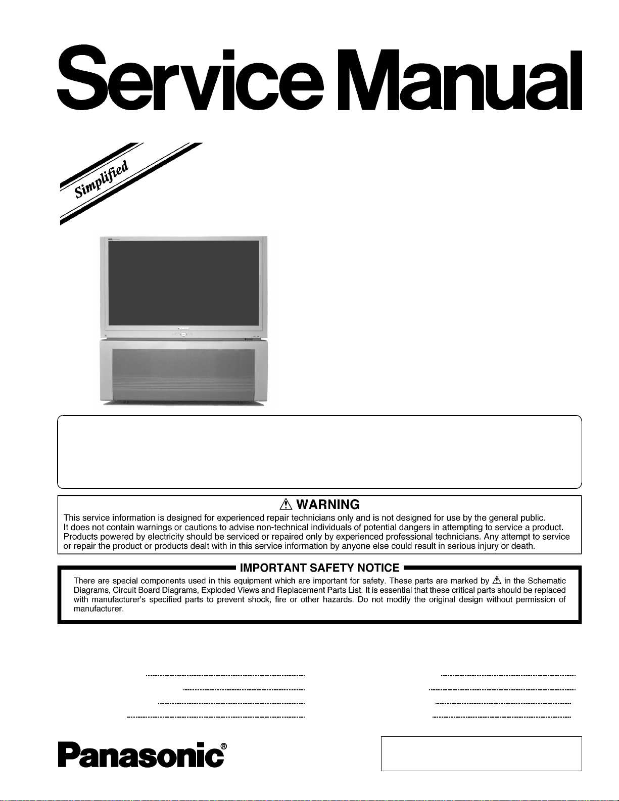
Leakage current hot check
Plug the AC cord directly into the AC outlet. Do not use an
isolation transformer during the check.
Connect a 1.5kΩ 10 watt resistor in parallel with a 0.15µF
capacitor between an exposed metallic part and ground.
Use earth ground, for example a water pipe.
Using a DVM with a 1000 ohms/volt sensitivity or higher,
measure the AC potential across the resistor.
Repeat the procedure and measure the voltage present
with all other exposed metallic parts.
Verify that any potential does not exceed 0.75 volt RMS. A
leakage current tester (such a Simpson model 229,
Sencore model PR57 or equivalent) may be used in the
above procedure, in which case any current measure must
not exceed 0.5 milliampere.If any measurement is out of the
specified limits, there is a possibility of a shock hazard and
the receiver must be repaired and rechecked before it is
returned to the customer.
Hot check circuit
Insulation test
Connect an insulation tester between an exposed metallic
part and A.C. line. Apply 1080VAC/60Hz for 1 second.
Confirm that the current measurement is 0.5mA ~ 2.0mA.
Repeat test with other metallic exposed parts.
X-ray radiation
WARNING
The potential source of x-ray radiation in the PTV set is
in the high voltage section and the picture tube.
NOTE
It is important to use an accurate, calibrated high
voltage meter.
Apply all black video signals (1080i) and confirm high
voltage measures 31.5 ± 1.0kV. If the high voltage is not
within the range, change C514 (in D-Board) to 1800pF,
2000pF, 2400pF or 2700pF until the desired value
isobtained.Apply NTSC white pattern and confirm the high
voltage measures 30.1 ± 1.5kV. Apply HD 1080i white
pattern and confirm the high voltage measures 30.1 ±
1.5kV.
3
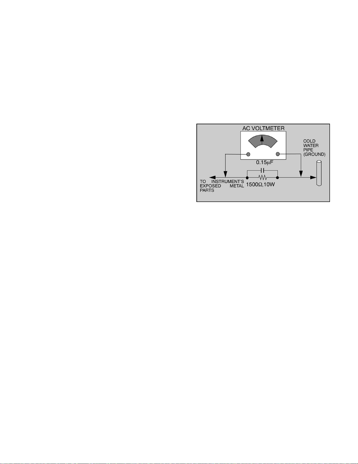
2 About lead free solder (PbF)
NOTE
Lead is listed as (Pb) in the periodic table of elements.
In the information below, Pb will refer to lead solder, and PbF will refer to Lead Free Solder.
The lead free solder used in our manufacturing process and discussed below is (Sn+Ag+Cu).
Thatis Tin (Sn), Silver (Ag) and Copper (Cu) although other types are available.
This model uses Pb Free solder in it’s manufacture due to environmental conservation issues. For
service and repair work, we’d suggest the use of Pb free solder as well, although Pb solder may be
used.
PCBs manufacturedusing lead free solder will have the “PbF” or a leaf symbol stamped on the
back of PCB.
CAUTION
· Pb free solder has a higher melting point than standard solder. Typically the melting point is 50 ~ 70 °F (30 ~ 40 °C) higher.
Please use a high temperature soldering iron and set it to 700 ± 20 °F (370 ± 10 °C).
· Pb free solder will tend to splash when heated too high (about 1100 °F or 600 °C).
If you must use Pb solder, please completely remove all of the Pb free solder on the pins or solder area before applying Pb
solder. If thisis not practical, be sure to heat the Pb free solder until it melts, before applying Pb solder.
· After applying PbF solder to double layered boards, please check the component side for excess solder which may flow onto
the opposite side.
Suggested Pb free solder
There are several kinds of Pb free solder available for purchase. This product uses Sn+Ag+Cu (tin, silver, copper) solder.
However, Sn+Cu (tin, copper), Sn+Zn+Bi (tin, zinc, bismuth) solder can also beused.
4
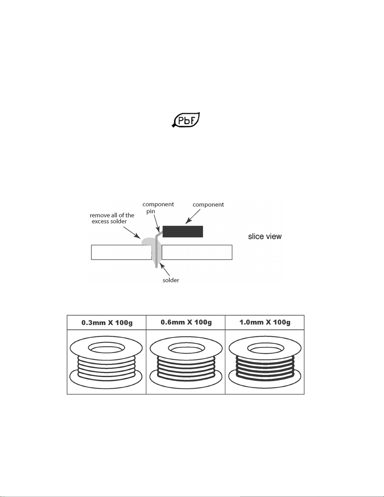
3 Important safety tests
Measuring H.V.
The anode caps are cemented to the CRTs. To gain access
for high voltage measurement, remove the red CRT’s
anode lead from the flyback transformer distributor. Grasp
the anode lead protective cap at its bottom and squeeze it
against thelocking cap body inside, rotate 1/4 turn counter
clockwise and pull the anode lead sleeve out of the FBT
distributor. Connect a high voltage positive lead from your
H.V. meter to the FBT distributor, and the common negative
lead to cold ground
FBT leads removal
Note:
Reinsert the anode lead into the FBT distributor until it is
tightly and fully seated. Turn the locking cap clockwise to
lock in place.
(EHT) Protector operation check
With the cabinet back removed, apply a nominal 120V A.C.
to the PTV.
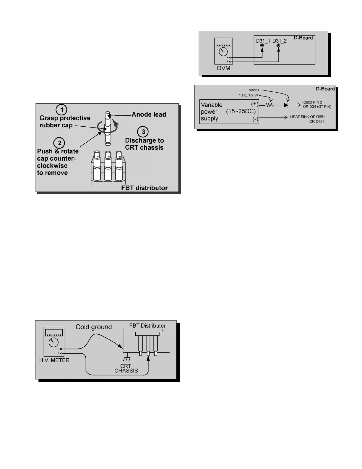
Over voltage test
Preparation:
1. Turn PTV “OFF”
2. Connect a NTSC signal generator to the antenna
terminal.
3. Connect DVM positive lead to D31 pin 2 and
negative lead to D31 pin 1 on D-Board
DVM and power supply connection
5. Connect the 15 ~ 25 V DC variable power supply
positive lead to D34 or IC802 pin 2 (D Board) and
negative lead to heat sink of Q551 or D825
Procedures:
1. Apply a NTSC white pattern.
2. Turn PTV ON.
3. Adjust the picture or brightness controls so that
the DVM reads 12.7 ± 0.4 volts.
4. Increase the variable power supply until set turns
off. The set should turn off at 12.7 ± 0.4 volts
(DVM) and high voltage less than 36.4kV.
5. If the DVM reading is other than 12.7 ± 0.4 volts,
readjust picture or brightness control and repeat
steps 3.
6. Turn off the variable supply and confirm that the
set will turn on by pulling out AC plug socket and
connecting it again.
H.V. measurement
4. Connect a H.V. meter (static type, class 0.1) with
high voltage leads to high voltage distributor on FBT.
5
4 Service notes
NOTE
These components are affixed with glue. Be careful not to
break or damage any foil under the component or at the
pins of the ICs when removing. Usually applying heat to the
component for a short time while twisting with tweezers will
break the component loose.
Leadless chip component (surface mount)
Chip components must be replaced with identical chips due
to critical foil track spacing. There are no holes in the board
to mount standard transistors or diodes. Some chips
capacitor or resistor board solder pads may have holes
through the board,however the hole diameter limits
standard resistor replacement to 1/8 watt. Standard
capacitor may also be limited for the same reason. It is
recommended that identical components be used.
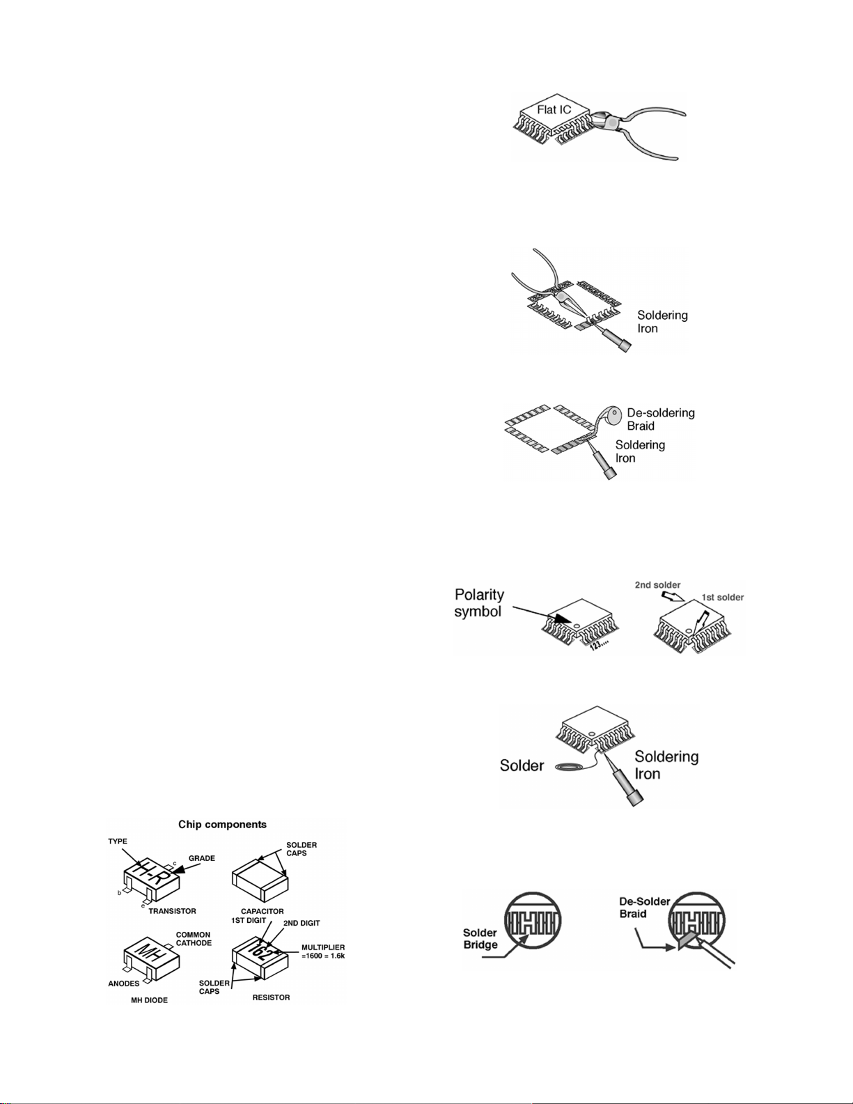
Chip resistor have a three digit numerical resistance code,
1st and 2nd significant digits and a multiplier. Example: 162
= 1600 or 1.6kΩ resistor, 0 = 0Ω (jumper).
Chip capacitors generally do not have the value indicated
on the capacitor. The color of the component indicates the
general range of the capacitance.
Chip transistors are identified by a two letter code. The first
letter indicates the type and the second letter, the grade of
transistor.
Chip diodes have a two letter identification code as per the
code chart and are a dual diode pack with either common
anode or common cathode. Check the parts list for correct
diode number.
Component removal
1. Use solder wick to remove solder from component end
caps or terminal.
2. Without pulling up, carefully twist the component with
tweezers to break the adhesive.
3. Do not reuse removed leadless or chip components
since they are subject to stress fracture during removal.
Chip component installation
1. Put a small amount of solder on the board soldering
pads.
2. Hold the chip component against the soldering pads
with tweezers or with a miniature alligator clip and apply
heat to the pad area with a 30 watt iron until solder
flows. Do not apply heat for more than 3 seconds.
using a desolder braid
2. Put the iron wire under the pins of the Flat IC and pull it
in the direction indicated while heating the pins using a
soldering iron. A small awl can be used instead of the
iron wire.
3. Remove the solder from all the pads of the Flat IC by
using a de solder braid
4. Position the new Flat IC in place (apply the pins of the
Flat IC to the soldering pads where the pins need to be
soldered). Properly determine the positions of the
soldering pads and pins by correctly aligning the polarity
symbol
5. Solder all pins to the soldering pads using a fine tipped
soldering iron
6. Check with a magnifier for solder bridge between the
pins or for dry joint between pins and soldering pads. To
remove a solder bridge, use a desolder braid as shown
in the figure below
How to replace flat ic (required tools)
1. Remove the solder from all of the pins of a Flat IC by
6

IMPORTANT
To protect against possible damage to the solid state
devices due to arcing or static discharge, make certain
that all ground wires are securely connected.
CAUTION
The power supply circuit is above earth ground and the
chassis cannot be polarized. Use an isolation
transformer when servicing the receiver to avoid
damage to the test equipment or to the chassis.
Connect the test equipment to the proper ground(HOT
or COLD) when servicing, or incorrect voltages will be
measured.
WARNING
This receiver has been designed to meet or exceed
applicable safety and x-ray radiation protection as
specified by government agencies and independent
testing laboratories.
To maintain original product safety design standards
relative to x-ray radiation and shock and fire hazard,
parts indicated with the symbol
on the schematic
must be replaced with identical parts. Order parts from
the manufacturer’sparts center using the parts numbers
shown in this service manual, or provide the chassis
number and the part reference number.
For optimum performance and reliability, all other parts
should be replaced with components of identical
specification.
7
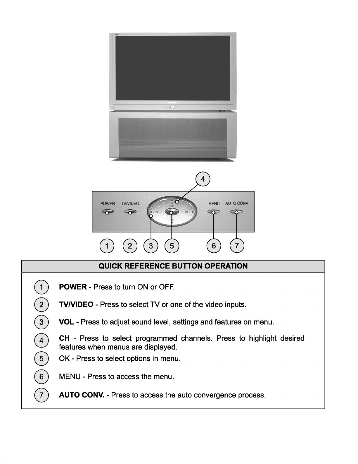
5 PTV Location of controls
8

6 Receiver feature table
FEATURE/MODEL PT-47XD64J
CHASSIS AP833
MICRO 256K
MENU LANGUAGE ENGLISH
CLOSED CAPTION X
V-CHIP (USA/CANADA) USA
CHANNEL INFO BANNER X
ATSC / QAM TUNING X
VIDEO INPUT SKIP SKIP
CHANNEL COUNT 181
PIP (1T), 2T PIP (2T), 2T SPLIT 2T SPLIT
2RF X
REMOTE CONTROL (W/LIGHT) EUR7627Z10
CRT SUPPLIER MDDA (CENTAUR)
SCREEN W/PROT SCREEN
CHASSIS P9M
COMB FILTER 3D Y/C
HEC/VEC (X=BOTH) X
NEW YNR X
VM X (SELECTABLE)
V/A NORM (X=BOTH) X
COLOR TEMP X
PRESET/INPUT LABELING X
VIDEO PICTURE MEMORY X
DIGITAL SCAN RATE 1080i, 540p
NTSC LINE DOUBLER 540p PROGRESSIVE (NEW)
MTS/SAP/DBX X
BUILT-IN AUDIO POWER 15W x 2
No. OF SPEAKERS 4
BASS/BALANCE/TREBLE CONTROL X
AI SOUND X
SURROUND X
SPATIALIZER/BBE BBE
A/V IN (REAR/FRONT) 4(3/1)
A/V PROGRAM OUT X
AUDIO OUT (FAO: F, VAO:V) F
COMPONENT INPUT (Y, Pb, Pr) 2
S-VIDEO INPUT (REAR/FRONT) 2/1
HDMI/HDCP INPUT 1
DIGITAL AUDIO OUT (AC-3/PCM) 1
CableCARD Slot 1(BACK)
(PCMCIA/SD) 1(FRONT)
Note:
Specifications are subject to change without notice or obligation.
9
7 Board description table
BOARD PART NUMBER DESCRIPTION
A-BOARD TNP2AH051AC MAIN CHASSIS
CD-BOARD TNP2AA166 CONVERGENCE OPTICAL SENSOR
D-BOARD TNP2AH056AB POWER SUPPLY
* DC-BOARD TNP2AA163 CONVERGENCE CIRCUIT
* DG-BOARD TNP2AA132AB MPU, VIDEO SIGNAL PROCESSING
* DV-BOARD TNP2AA133 HDMI DECODER
* DT-BOARD TNP2AA144AD HIGH DEFINITION TUNER
G-BOARD TNP2AA195 FRONT A/V INPUT
H-BOARD TNP2AA134 REAR A/V INPUTS
* JG-BOARD TNP2AA140AB SD,PC JPEG VIEWER
K-BOARD TNP2AA196 KEYBOARD PANEL
LB-BOARD TNP2AA147AB BLUE PRT
LG-BOARD TNP2AA146AB GREEN PRT
LR-BOARD TNP2AA145AB RED PRT
R-BOARD TNPA0615AB IR SENSOR
T-BOARD TNP2AA136 SUB-POWER
NOTE
When ordering a replacement board assembly, append an “S” to the board number
EXAMPLE
To order the A Board, the replacement board is TNP2AH051ACS
*
DC-Board, DG-Board, DV-Board, DT-Board and JG-Board are non-serviceable boards, except for the connectors JG1, JG2,
JK5001, JK5002, JK8002 and JK8003. If any of these boards are defective, replace it with a new one.
10
8 Auto diagnosis feature
This receiver incorporates a self diagnosis feature. With this
feature it will be easier for the technician to detect failures.
There is a LED located by the keyboard on the front panel, this
LED will start flashing when SOS is detected by the circuits
locatedin specific areas, depending on how many times the
LED is flashing, this will indicate what circuit should be
checked. Make a count of flashing and see the table shown
below. Please use this feature effectively especially for
intermittent problems.
NUMBER OF
FLASHES
1 POWER SUPPLY AND/OR
2 IC1006 (DG-BOARD)
3 CONVERGENCE (DC-BOARD)
4 HHS (FLYBACK)
5 GC2M (DG-BOARD)
6 GC2S (DG-BOARD)
7 GC2V (DG-BOARD)
8 FAN
POSSIBLE CAUSE
VERTICAL
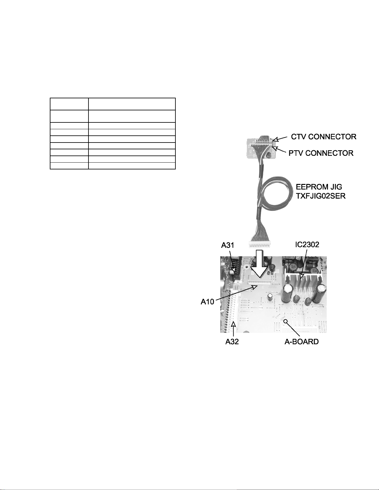
9 EEPROM copy jig
This PTV has a feature that allows to clone convergence from
main EEPROM data adjustments from a PTV to other by
connecting a jig to the PTV set, or can be used to back-up data
before making adjustments. A jig part number TXFJIG02SER,
is availablethrough Matsushita/Panasonic Services.
Preparation:
To connect this jig, remove the lower back cover as
instructed on disassembly for service section on this service
manual and insert the jig into A10 connector located on ABoard. (See figure)
Procedure to copy data:
1. Enter to service mode and display service menu (see
page 23).
2. Select “AREA” DAC and then press OK button on
remote to enter. Press VOL right/left to select one of the
following options then press OK:
· Select ALL to copy all main EEPROM data
· Select ADJ to copy only adjustment data.
· Select FIX to copy only fix data
3. To copy data from main EEPROM to jig,select “IN→EX”
DAC and press OK button on remote.
4. To copy data from jig to main EEPROM, select “EX→IN”
DAC and press OK button on remote.
Procedure to copy convergence:
1. Enter to service mode and display service menu
2. Select “FINE” DAC and press OK on remote.
3. Press “8” on remote.
4. Select from and then press OK on remote:
· INT to copy data from internal EEPROM to jig
· EXT to copy from jig to internal EEPROM.
5. Select an option from the menu with CH keys and
confirm with OK:
· DEFAULT:default factory preset
· CURRENT:to copy the current (receiver data or jig
data) convergence adjustments to memory.
· NOT USE: to back up data.
· ALL: to copy all data.
NOTE:
The stated as default factory preset contain the
factory DATA; Use this option when data was
lost or when adjustment is lost completely.
6. Select destination to copy (INT or EXT) and confirm with
OK.
7. Once an option is selected the copy process begins.
8. Once finished, the receiver shuts down for a moment to
reinitialize.
9. Remove the copy jig from A10.
EEPROM copy jig connection
11
10 Disassembly for service
NOTE:
Board ground wires may have to be disconnected to
disassemble some boards. All ground wires must be
reconnected using jumper leads, if necessary, before power
is applied to PTV for service.
Speaker grille removal
Speaker grille, is secured to the cabinet of the PTV with 1
velcro dot and 2 screws at the bottom. Take the screws out
and grip panel from the bottom, pull slightly backward and
at the same time pull down to uncouple the 4 tabs. When
reassembling,make certain to firmly press on the panel
where the velcro dot is and that the four tabs are properly
inserted in the front cover.
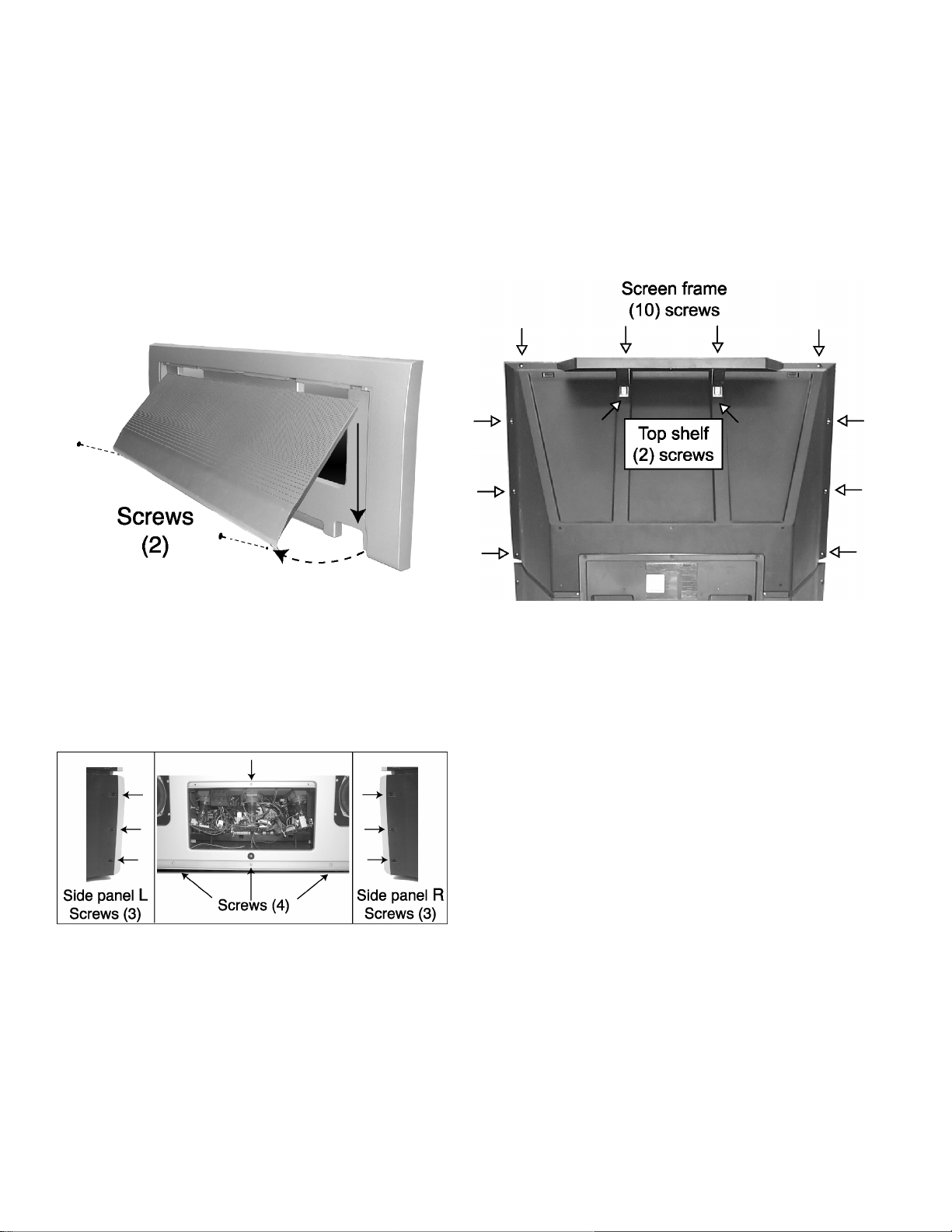
Screen frame removal
1. First, remove the front panel.
2. Below the screen, remove the 5 screws from the tabs,
just below the front A/V inputs.
3. Remove the 10 screws from the back cover. Atthis point
the top shelf must be removed from the back cover (2
screws).Be careful when removing the screen frame, try
removing the screws from the sides first and leave the
top screws at last, besure to hold the frame when
removing the last screws.
Speaker grill removal
Front cover replacement
1. Remove the speaker grille.
2. Remove the cabinet front board by removing the 2
screws in the middle section.
3. Remove the screws from the middle section (4) of the
front panel and both side panels (3 in each side from the
back, see picture).
4. Pull the front panel from the bottom slightly downwards
to unlock the tabs and remove.
Speakers replacement
1. Each speaker set is conformed by a tweeter and a
woofer mounted in an enclosure fixture. This fixture is
fastened to the main cabinet board by 6 screws. The
tweeter and woofer are mounted in the fixture with 2
screws (each speaker). It isrecommended for speaker
servicing to remove the speaker enclosure.
2. Disconnect the R (A22) and L (A21) speaker connectors
from A-board.
Screen frame removal (back view)
4. Tilt the assembly forward while lifting it out of place.
CAUTION:
At this point the keyboard, A/V inputs and
convergence sensors, must be disconnected from
K-board and G-board, otherwise the cables and
connectors could get damaged.
Screen assembly
1. Remove the screen frame. See screen frame removal
procedure above.
2. Place screen frame face down on a soft surface.
3. If necessary remove G-board and/or K-board.
4. If necessary disassemble A/V panel removing the
screws (4) and tilt the panel upwards and release it from
screen frame.
5. Remove the screws from the screen frame (20), be
careful not to damage the convergence sensors (see
picture).
12
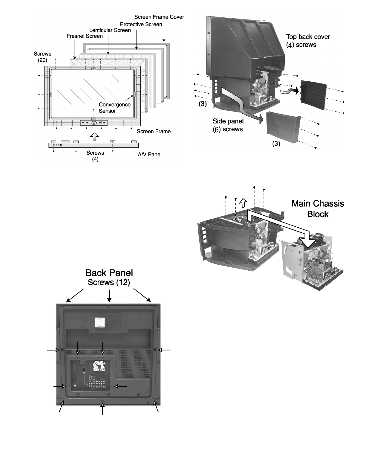
Screen assembly (Inside view)
6. Carefuly lift screen frame leaving the screen frame
cover with the 3 screens (Fresnel, Lenticular, Protective)
on top of it.
Keyboard and front A/V inputs removal
1. Unplug the connectors from keyboard and front A/V
inputs assemblies. Remove the screws affixing the
keyboard (4 screws) and front A/V inputs (3 screws) and
tilt the A/V panel assembly upward and release it
fromthe screen frame.
Back panel removal
1. The back panel is fastened to the cabinet by 12 screws.
See picture for screw location.
2. Remove the 4 screws from the cabinet body that holds
the upper cabinet cover and carefully remove it.
3. The main chassis block is secured to the main body
cabinet by 4 screws on the top (see picture).
Chassis removal
Mirror removal
The mirror is attached inside the cabinet cover. Carefully
remove the cabinet cover to access its interior surface and
remove the screws securing the brackets that hold the
mirror at the top and sides to the mirror.
Back panel removal
Main chassis block
1. After removing the screen frame and front cover,
remove the side panel from each side (each side panel
is fastened by 6 screws, 3 at front and 3 in the back).
13
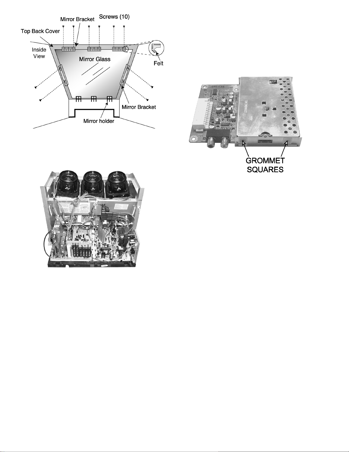
Mirror Removal (Inside View)
10.1. Chassis assembly
The chassis assembly shown in figure includes all the electrical
and optical (light box) components
DV-Board
1. Plugs onto A-Board at the A51 connector.
NOTE:
This board is non-serviceable.
When removing this board pull carefully.
2. This board has two Grommet squares, be careful to do
not screw too tight, otherwise this grommet screw hole
will get stripped.
Chassis back view
A/V BACK COVER ASSEMBLY
This assembly is secured to H-Board by 8 screws.
H-Board
1. H-Board is connected to DG-board with H1 connector.
2. Pull carefully to the right to disconnect.
DT-Board
1. This board has a metal frame holder that is fastened to
A-Board with 2 screws. This metal frame must be
removed first before trying pulling up DT-board,
otherwise it can be damaged.
2. This board has grommet squares, be careful to do not
screw too tight, otherwise the grommet screw hole will
get stripped.
3. After removing the metal frame pull up carefully from
A41 connector in A-Board.
NOTE:
This board is non-serviceable. Except for JK8002
and JK8003.
When removing this board pull carefully.
NOTE:
This board is non-serviceable. Except for JK5002
(ANALOG AUDIO JACKS) and JK5001 (DV1
connector)
When removing this board pull carefully.
DG-Board
1. Plugs onto A-Board at A13 and A14 connectors (DG3
and DG4 respectively).
2. Remove plug cables from connectors DG5 and DG6.
NOTE:
This board is non-serviceable.
When removing this board pull carefully.
A-Board
1. A-Board is secured to the chassis tray with six screws.
2. The A-Board is mated to D-Board by four flexible
connectors (male side of connectors): A1, A2, A3 & A4.
To remove this board, unplug the connectors of A-Board
pulling from the sides of each connector.
NOTE:
Some tie wraps that secure the wire dressings may
need to be unfastened for chassis removal.
3. Remove plug connector in A6 that goes to G-Board
(G1).
4. Remove plug connectors in A7, A8 that goes to K-board
(K1) and R-board (R1).
D-Board
1. D-Board is secured to the chassis tray with five screws.
2. The D-Board is mated to A-Board by four connectors
(female side of connectors): D1, D2, D3 & D4. To
remove this board, unplug the connectors on the ABoard pulling from the sides of each connector.
NOTE:
Some tie-wraps that secure the wire dressings may
14
need to be unfastened for chassis removal.
DC-Board
1. Plugs onto the D-Board at the D21, D22 and D23 (DC1,
DC2 and DC3 respectively) connectors.
NOTE:
This board is non-serviceable.
When removing this board pull carefully.
R-Board
1. This board is secured to the upper front side of the light
box by one screw, and plugged to R1 connector from A7
on A-Board.
LR, LG and LB Board
1. Each board is plugged into the socket on the PRT neck,
LR-Board on red PRT, LG-Board on green PRT and LBBoard on blue PRT.
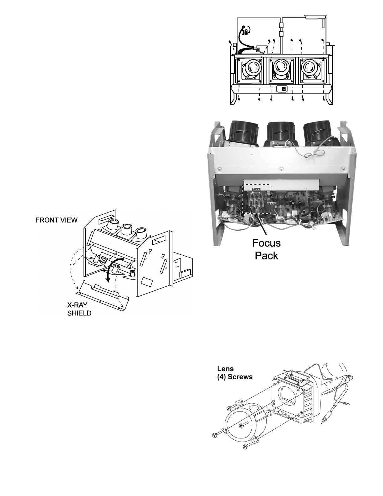
10.2. Disassembly for CRT
replacement
To facilitate CRT replacement, the complete CRT mounting
chassis does not need to be removed.
1. Remove the main chassis block from the cabinet.
2. Remove the optical bracket metal cover (front side x-ray
shield) by removing 3 screws on top.
CRT replacement
CRT replacement
3. Remove the defective CRT anode lead from the high
voltage distributor block that is mounted on the flyback
transformer. Discharge to CRT chassis.
4. Unplug connectors from D-Board. See board layout. D14
for red, D15 for green and D16 for blue.
5. Unplug the defective CRT black DAG ground connector
from the CRT Board.
6. Remove the CRT Board from the defective CRT neck.
7. Remove (4) screws from the defective CRT housing.
Caution:
Do not remove the (4) CRT lens screws. Support the
CRT assembly when loosening screws.
Focus pack location
8. Release CRT anode lead from CRT chassis wire clamp and
all other wires from holders.
9. Loosen a screw that secures the DY and remove it from the
CRT neck.
Caution:
To insure protection against x-ray radiation, the lens
must be mounted in place at all times when power is
applied to the PTV
CRT replacement
1. Remove CRT focus lens assembly (4 screws)
CRT assembly
2. Lay CRT face down on a soft cloth.
15

3. Note position of yoke with centering tabs and remove
from defective CRT.
4. Remove CRT DAG ground from defective CRT. Mount
it on the replacement CRT exactly as it was on the
defective CRT.
Note:
Replacement CRT is supplied with H.V. anode lead
attached.
5. Wire the anode lead wire.
6. Install yoke with other CRT neck assemblies on CRT
neck in the same order and position as removed from
the defective CRT.
7. Press yoke against bell of CRT and tighten the clamp
just snug enough so it will not easily shift.
8. Assemble CRT focus lens assembly to new CRT with
(4) screws. Make sure focus lens adjustment nut is in
the same location as on other CRT focus lens
CRT screw tightening order
Note:
Please assemble with screws in the order shown
and tighten with the same torque.
16
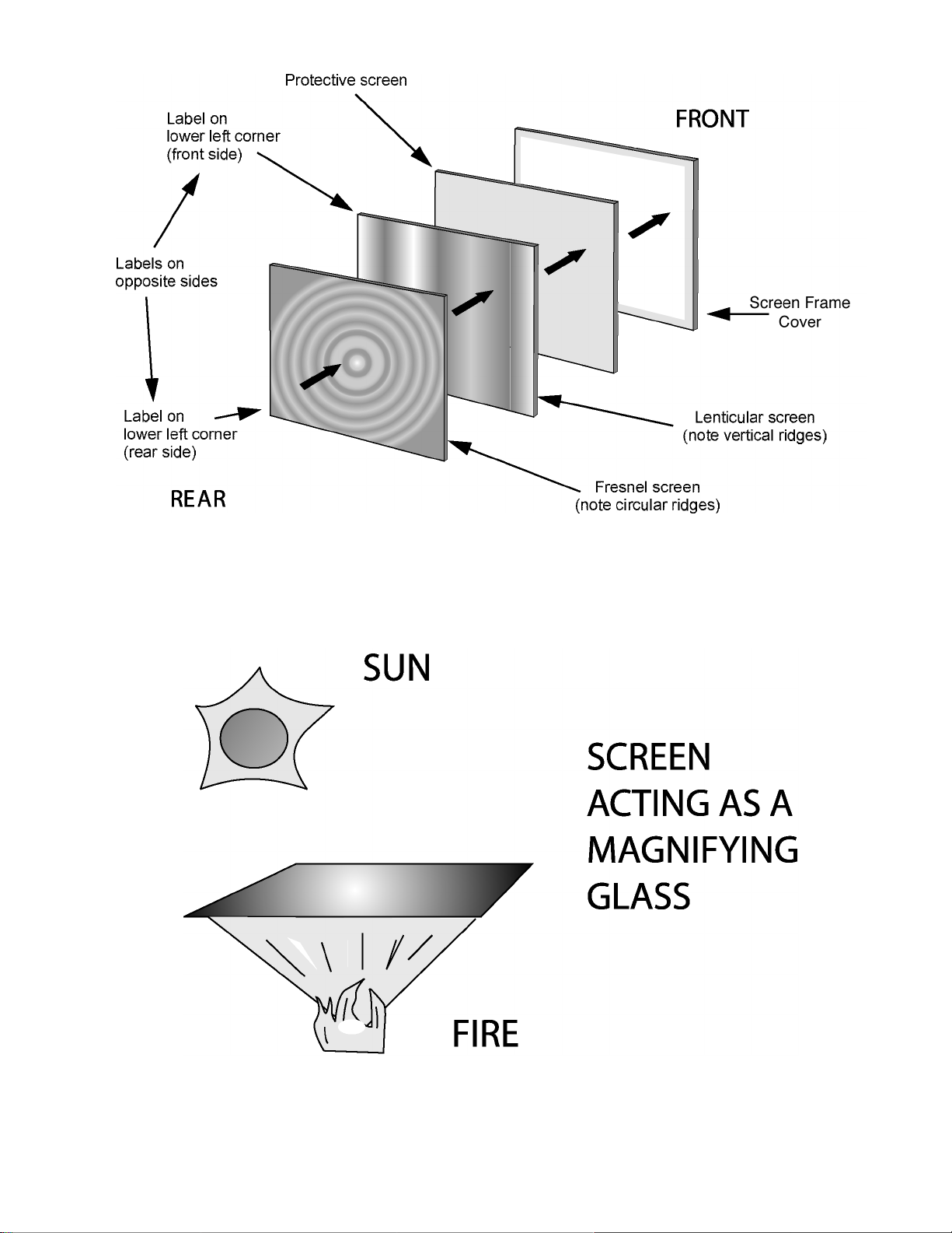
10.3. PTV screen assemblies
Screen assemblies
10.4. Screen assemblies warning
When storing or disposing of screen assemblies, be sure not to place them in direct sunlight. These screens may act as a
magnifying glass and could cause a fire.
17
11 B + voltages table
Preparation:
Set the following controls
· Picture to Normal
· Bright to Normal
· Volume to MIN (0)
Procedure:
1. Apply a NTSC COLOR BAR pattern
2. Connect the negative lead of the digital voltmeter to TPGND1 (cold ground).
3. Connect the positive lead of the digital voltmeter to each test point and confirm the B+ voltages.
No. D-Board Test point Voltage
1 C830 (+) 138.6±1.0
2 TPD13 20.0±1.5
3 TPD12 19.5±1.5
4 TPD11 -20±1.5
5 TPD10 22.5±1.5
6 C845 (-) -22.5±1.5
No. A-Board Test points Voltage
1 TP118 5.0±0.5
2 TP114 2.5±0.5
3 TP070 5.0±0.5
4 L893 9.0±0.5
5 TP137 30.0±0.5
18
12 Service Mode (electronic controls)
This receiver has electronic technology using the IC bus
concept. It performs as a control function and it replaces many
mechanical controls. Instead of adjusting mechanical controls
individually, many of the control functions are now performedby
using “on screen display menu”. (The service adjustment
mode.)
NOTE:
It is suggested that the technician reads all the way through
and understand the following procedure for entering/exiting
the service adjustment mode; then proceed with the
instructions working with the receiver. When becoming
familiarwith the procedure, the flow chart for service mode
may be used as a quick guide.
12.1. Quick entry to service mode:
When minor adjustments need to be done to the electronic
controls, the method for entering the service mode without
removal of the cabinet back is as follows, using the remote
control:
1. Select SET-UP icon, enter “Program CH” and select
CABLE mode in “Input Setup” option.
2. Select TIMER icon and set SLEEP time for 30 Min.
3. Press “OK” then VOL up to exit menus.
4. Tune to the Channel 124.
5. Adjust VOLUME to minimum (0).
6. Press VOL ← (decrease) on receiver. Red “CHK” appears
in upper corner.
To toggle between aging and service modes:
While the “CHK” is displayed on the left top corner of the
CRT, pressing “OK” and “VOL” UP on the TV
simultaneously will toggle between the modes. Red
“CHK” for service modeand yellow “CHK” for aging.
7. Press POWER on the remote control to display the service
adjustment modes menu, select adjustment by pressing the
VOL right/left buttons and CH up/down buttons on the
remote and OK to enter the adjustment.
turned OFF. To exit the service mode, turn the TV OFF or
unplug the PTV from AC.
Other method
Press OK and POWER on the receiver simultaneously for
at least 2 seconds.The receiver momentarily performs a
self-check, tuned in channel 3 with a preset level of sound.
To completely make an entire reset of the PTV unplug AC
cord from AC outletand plug it back in, then turn PTV power
ON.Any programmed channels, channels caption data and
some others user defined settings will be erased when
performing this reset.
IMPORTANT NOTE
Always check that PTV exits the service mode
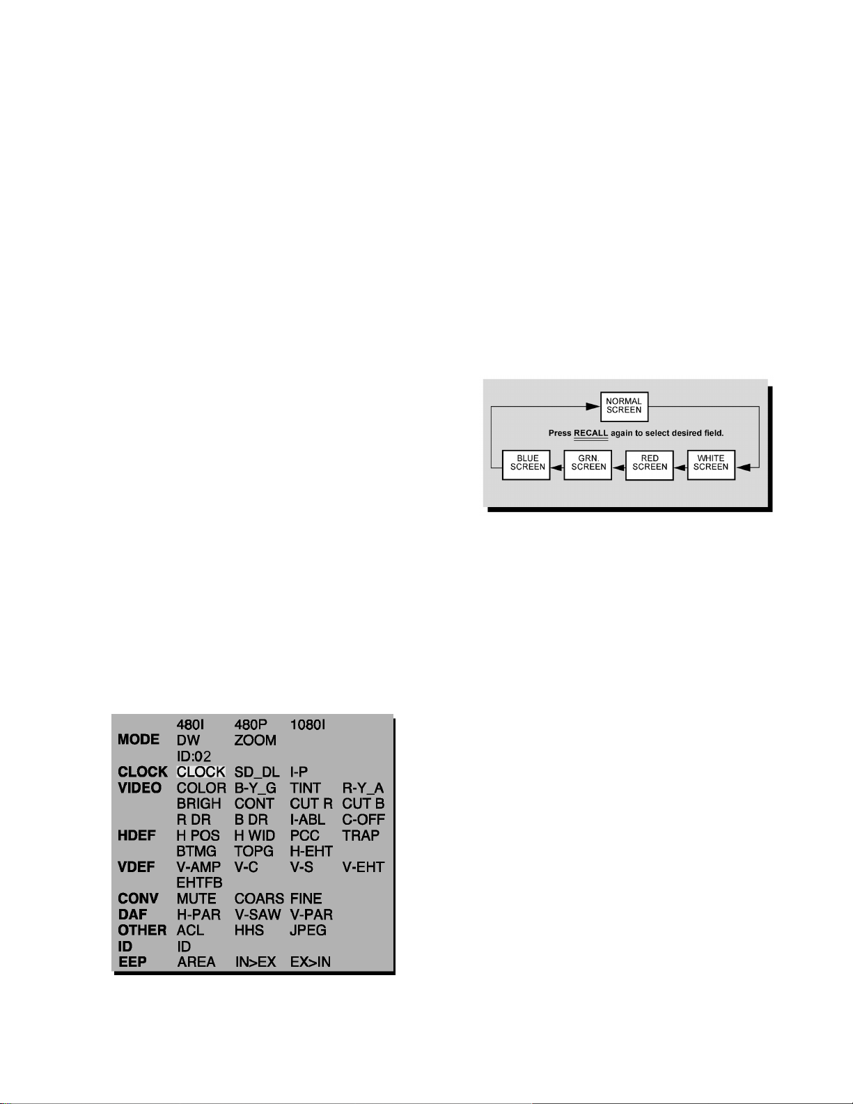
To check colors:
Press RECALL on the remote control when in service mode
(red “CHK” is displayed) to enter the purity field check
mode.
Color check
Service mode menu
12.2. Exiting the service mode:
This PTV goes out from service mode when it is unplugged or
19
12.3. Service adjustment default values for items
DESCRIPTION REGISTER FORMAT
NTSC (480i) 480i ZOOM 480P 480P ZOOM 1080i
CLOCK ADJ CLOCK 124 N/A N/A N/A N/A
FIRMWARE DOWNLOAD SD_DL 00 00 00 00 00
INTERLACED TO PROGRESSIVE I-P 00 N/A 00 00 N/A
COLOR COLOR 20 N/A N/A N/A 2A
MAGENTA TINT ADJ B-Y_G 2B N/A N/A N/A 34
TINT TINT 85 N/A N/A N/A 80
YELLOW TINT ADJ R-Y_A 96 N/A N/A N/A 83
SUB-BRIGHTNESS BRIGH 09 F8 N/A N/A N/A 0A 34
SUB-CONTRAST CONT 02 9F N/A N/A N/A 02 91
RED CUT-OFF CUT R 01 F5 N/A N/A N/A 01 F5
BLUE CUT-OFF CUT B 02 23 N/A N/A N/A 02 23
RED DRIVE RDR 64 N/A N/A N/A N/A
BLUE DRIVE BDR 42 N/A N/A N/A N/A
INDIVIDUAL ABL CHECK I-ABL VARIABLE N/A VARIABLE N/A VARIABLE
CUT OFF ADJ C_OFF 00 00 00 N/A 00
HORIZONTAL POSITIONING H POS 01 83 01 83 01 83 N/A 01 83
HORIZONTAL WIDTH H WID 51 51 51 N/A 51
PINCUSHION CORRECTION PCC 40 40 40 N/A 40
TRAPEZOID TRAP 81 81 81 N/A 81
BOTTOM CORNER PINCUSHION BTMG B0 B0 B0 N/A B0
TOP CORNER PINCUSHION TOPG B4 B4 B4 N/A B4
HORIZONTAL EHT PRESET H-EHT N/A N/A N/A N/A 31
VERTICAL SIZE V-AMP 00 94 00 94 00 94 N/A 00 94
VERTICAL LINEARITY V-C 87 87 87 N/A 87
VERTICAL S CORRECTION V-S 59 59 59 N/A 59
VERTICAL EHT PRESET V-EHT N/A N/A N/A N/A 1B
FLYBACK EHT PRESET EHTFB FF FF FF N/A FF
MUTE CONVERGENCE MUTE 00 00 00 N/A 00
COARSE ADJ COARS 00 00 00 N/A 00
FINE ADJ FINE 00 00 00 N/A 00
H DAF ADJUSTMENT H-PAR 0 0 0 N/A 0
V SAW DAF ADJUSTMENT V-SAW 0 0 0 N/A 0
V DAF ADJUSTMENT V-PAR 0 0 0 N/A 0
ACL ADJUSTMENT ACL 00 00 0 N/A 00
JPEG SERVICE MENU JPEG 00 00 0 N/A 00
ID* ID 02 02 02 02 02
AREA AREA FIX FIX FIX N/A FIX
*IMPORTANT:
The default ID register value should not be modified in any way, it has been already set to a factory default value specifically
for the model listed in this manual.
NOTE:
The above table shows the default values for the service items, this values can change depending on the serviced PTV.
20
13 CRT Set Up
CAUTION:
Insure that yoke plugs are reconnected on D-Board before
turning the PTV ON to prevent damage to the horizontal
output transistor and/or CRT’s.
1. Connect test generator to the antenna terminal and set for
a monoscope pattern.
2. Loosen yoke clamp, seat yoke against bell of CRT and
rotate to correct yoke tilt (compare to adjacent CRT).
Tighten yoke clamp.
3. Remove adhesive from centering tabs and set centering
tabs for zero correction.
4. Cover replacement CRT lens and static converge the tubes
not replaced, if needed. Check size and linearity of pattern
and adjust as required
5. Uncover replacement CRT lens and cover other two CRT
lenses. Adjust electrical and optical focus (lens), if required.
6. Uncover all CRT lenses and use yoke centering magnet to
converge replacement CRT (in center area of screen only)
with other two CRTs. Disregard of convergence in areas
other than center area.
7. Perform white balance adjustments.
13.1. Dynamic focus adjustments
1. Focus adjustments should be performed after 1 hour of
aging.
2. Use oscilloscope with 100 : 1 probe.
3. Apply a NTSC crosshatch pattern to adjust focus.
4. Adjust the red, blue and green focus VR on the focus block
for best focus of overall picture of each CRT.
5. To change DAF DATA, enter to service mode, then press
POWER on remote to display DACs menu, then select DAC
by pressing CH (RIGHT/LEFT) and VOL (UP/DOWN), then
press OK to enter to DAC, then adjust by pressing VOL
(RIGHT/LEFT); pressOK, to save press OK again or
OTHER key to exit without saving.
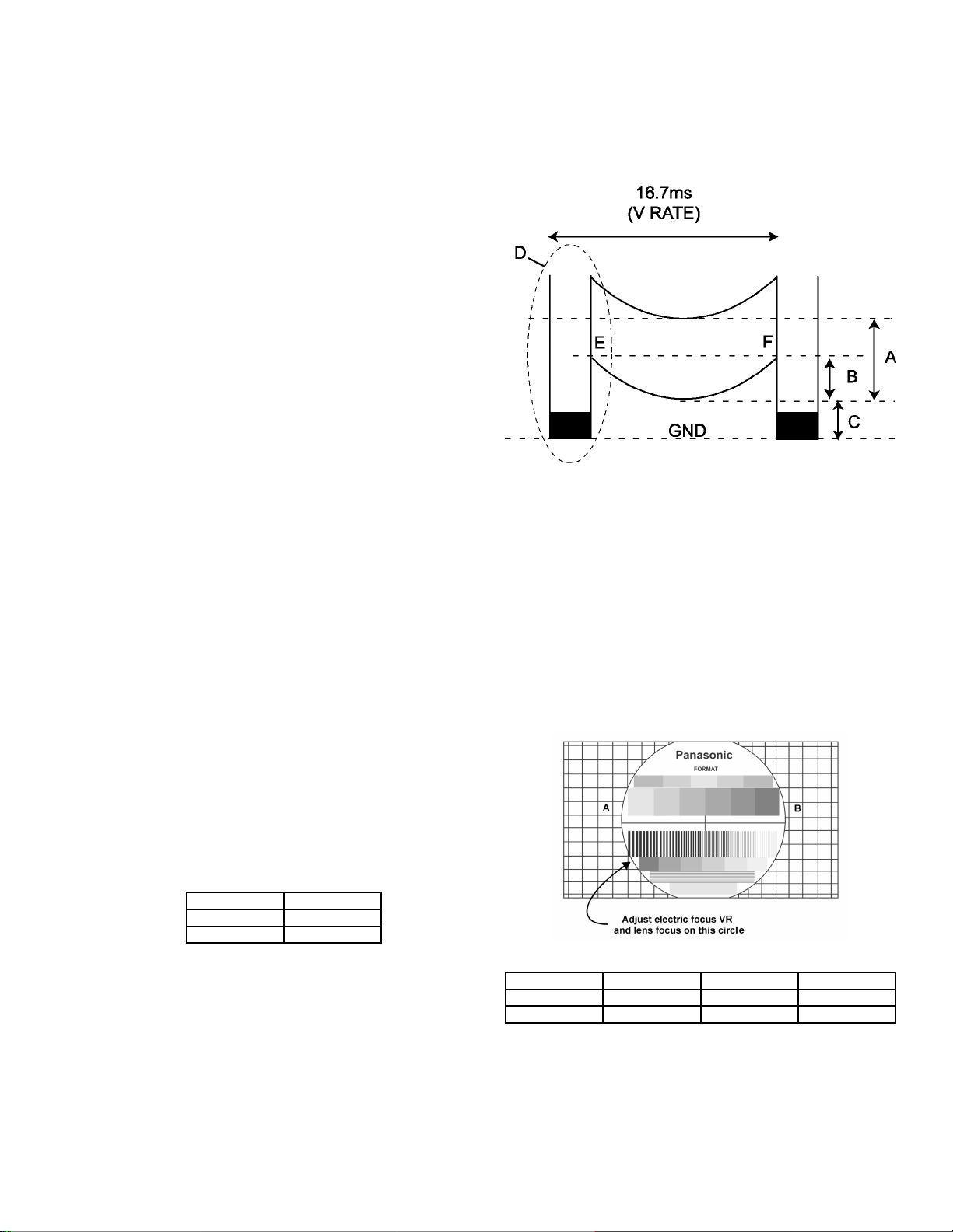
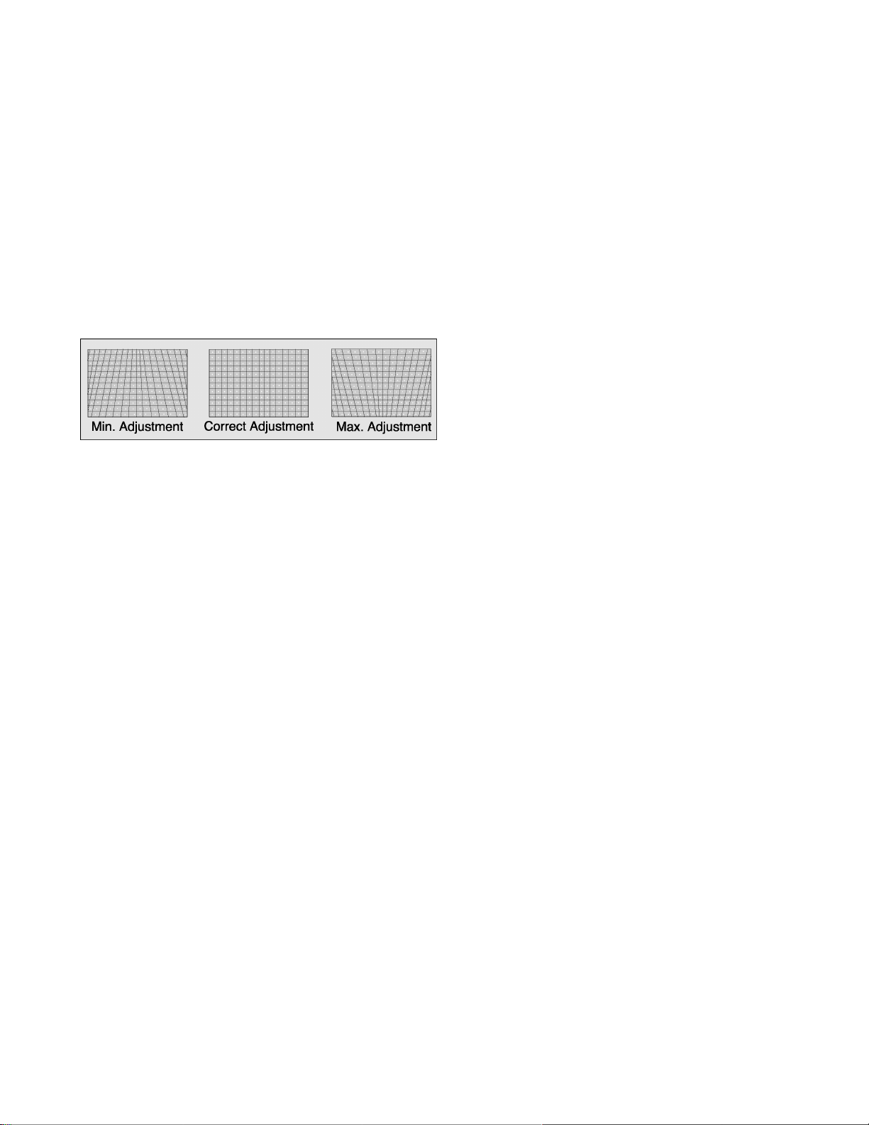
Procedure:
NOTE:
1080i, 480p, 480i pattern can be obtained from Panasonic’s
TU-DST51 set top box DTV decoder.
1. Enter to service mode and set the following default DATA
H-PAR +335
V-SAW +0
V-PAR +18
NOTE:
The signal (NTSC, 1080i and NTSC in ZOOM option),
should be applied and displayed to enter values for
specific format adjustment.
2. For 1080i set the default values.
3. For NTSC and NTSC ZOOM apply a white pattern and
perform the following steps.
4. Connect the scope probe to D30, GND to Q551 heat sink.
5. Confirm that level of A is 680 ± 50V, adjust
“H-PAR” DAC to set to specification level.
6. Confirm that the voltage level in D30 is similar between
point E and F, if not, adjust V-SAW DAC.
7. Confirm that level of B is 300 ± 40 V, adjust
“V-PAR” DAC to set to specification level.
8. Confirm that level of C is more than 20 V, adjust
“H-PAR” DAC to set to specification level.
Dynamic focus adjustment waveform
9. Confirm that step form (point D, H-DAF blanking) appears.
13.2. Focus - Electrical & optical
adjustments
(use for minor adjustment or for final adjustment, for complete
adjustment see following section.)
Electrical Adjustment
NOTE:
1080i, 480p, 480i pattern can be obtained from
Panasonic’s TU-DST51 set-top box DTV decoder.
1. Apply a crosshatch with dots pattern
Lens focus adjustment
RED GREEN BLUE
Electric focus B A/B A
Optical Focus B A/B A
2. Set VIDEO “C_OFF” DAC from 00 to 02, and project
only red. Adjust red focus VR so that focus is best
21
Focus pack
3. Adjust red lens focus (mechanical) until focus is best.
4. Adjust red focus VR again.
5. Set VIDEO “C_OFF” DAC from 00 to 01, and project
only green.
6. Repeat steps for green only.
7. Set VIDEO “C_OFF” DAC from 00 to 03, and project
only blue.
8. Repeat steps for blue only.
13.2.1. Focus - Optical lens adjustment
Optical adjustments
NOTE:
This adjustment normally should not require resetting
unless the lenses have been replaced or adjustment
has changed.
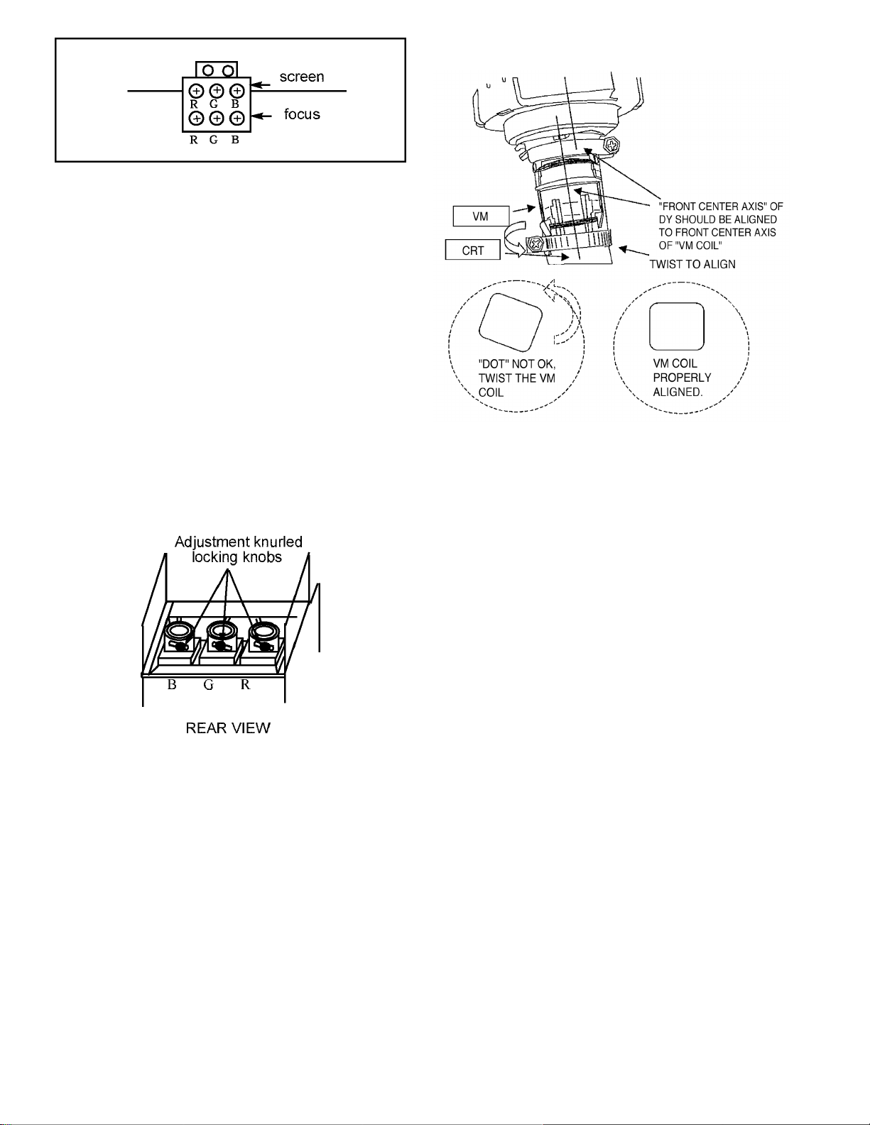
1. Optical focus adjustment is located on the top of
each CRT lens system. Loosen the adjustment
knurled locking knob.
coil to correct (see figure). If the screw was loosen, fix the
screw after correcting it (tighten).
4. Set VIDEO C_OFF DAC from 02 to 01, and project only
green.
5. Repeat step 3 for the green electrical focus.
6. Set VIDEO C_OFF DAC from 01 to 03, and project only
blue.
7. Repeat step 3 for the blue electrical focus.
8. Set VIDEO C_OFF DAC from 03 to 00, and project all
colors.
Optical lens focus adjustment
2. Turn the PTV ON. Apply and view a crosshatch with
dots pattern.
3. Adjust each lens focus for best focus while viewing
each CRT.
4. Cover the red and blue CRT, projecting green only.
Rotate the green lens for best focus around screen
center area.
5. Do the same for the red focus lens while projecting
red only.
6. Repeat for blue.
7. Align VM coils.
13.2.2. VM Coil Focus Adjustment
1. Apply a NTSC cross hatch pattern with dots.
2. Set VIDEO C_OFF DAC from 00 to 02, and project only red.
3. Confirm that the dots at center of pattern are not shown
‘diagonally’, if so, loose the VM coil screw and twist the VM
22
14 Electronic Adjustments
14.1. Horizontal phase adjustment
(H POS)
This adjustment is intended to correct the horizontal position of
the picture
NOTE:
1080i, 480p, 480i pattern can be obtained from Panasonic’s
TU-DST51 set-top box DTV decoder.
1. Apply a pattern that lets adjust the image to correct vertical
size (see above note).
2. Set VIDEO “C_OFF” DAC from 00 to 01 (to project only
green).
3. Set DAC MUTE from 00 to 01 (disabling digital
convergence).
4. Turn green deflection yoke until line is perfectly horizontal.
5. Adjust “H POS” DAC data so that pattern is in the center of
screen.
6. Enable digital convergence by changing DAC MUTE from
01 to 00.
7. Set VIDEO “C_OFF” DAC from 01 to 00
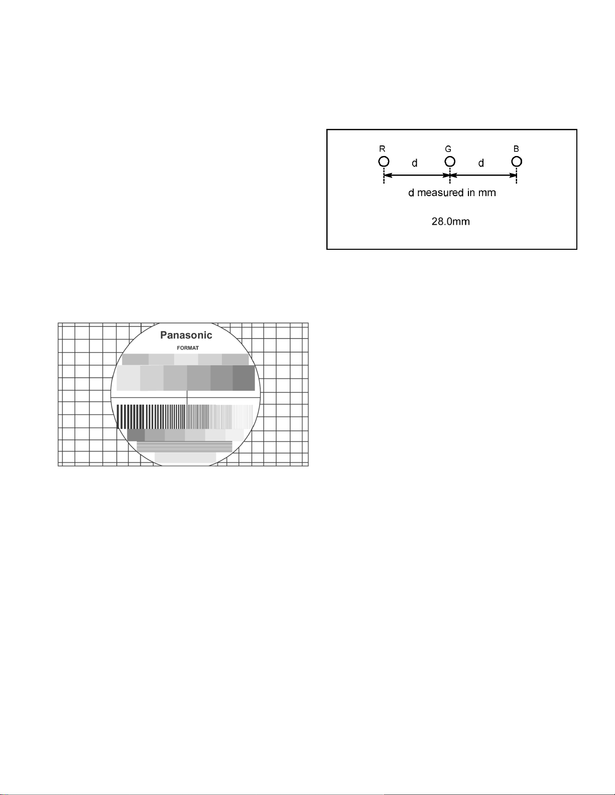
7. Set VIDEO “C_OFF” DACfrom 01 to 03 to project onlyblue.
Adjust deflection coil until the horizontal center line matches
the pattern of the grid and is leveled.
8. Adjust blue centering magnets until the pattern center is at
the appropriate distance as indicated on the following
figure.
Centering magnets adjustment
9. Set VIDEO “C_OFF” DAC from 01 to 02 to project only red.
10. Adjust red deflection coil until the horizontal center line
matches the pattern of the grid and is leveled.
11. Adjust red centering magnets until the pattern center is at
the appropriate distance as indicated on figure.
12. Enable digital convergence by changing DAC MUTE from
01 to 00.
13. Set VIDEO “C_OFF” DAC from 02 to 00. Following the
adjustment, make sure that all deflection coils are pushed
completely toward the CRT cones and that all screws are
tightened.
14.2. Centering magnets adjustment
(only for models where apply)
NOTE:
1080i, 480p, 480i pattern can be obtained from Panasonic’s
TU-DST51 set-top box DTV decoder.
Procedures:
1. Apply a crosshatch pattern with dots.
2. Set VIDEO “C_OFF” DAC from 00 to 01 to project only
green.
3. Set DAC MUTE from 00 to 01 (disabling digital
convergence).
4. Loose the deflection coil screw on the green CRT.
5. Adjust green deflection coil until the horizontal center line is
horizontal.
6. Adjust centering magnets until the green pattern is equal on
left and right. Adjust also for horizontal and vertical tilt.
NOTE:
Push deflection coil to top of CRT neck, then tighten
deflection screw after adjusting each CRT centering and
tilt.
14.3. Vertical linearity adjustment
(V-C and V-S)
This adjustment is intended to make the picture vertically
proportional (top, center and bottom)
NOTE:
1080i, 480p, 480i pattern can be obtained from Panasonic’s
TU-DST51 set-top box DTV decoder.
1. Apply a pattern that lets adjust the image to correct vertical
linearity (see above note).
2. Set VIDEO “C_OFF” DAC from 00 to 01 (to project only
green).
3. Set DAC MUTE from 00 to 01 (disabling digital
convergence).
4. Adjust centering magnets so that the center of the pattern
get aligned with screen frame center.
5. Adjust VDEF “V-C” and “V-S” DAC until vertical size is
proportional on top and bottom. Confirm to correct linearity
in the middle of the screen.
6. Set DAC MUTE from 01 to 00 (disabling digital
convergence).
7. Set VIDEO “C_OFF” DAC from 01 to 00
23
14.4. Vertical size adjustment (VAMP)
This adjustment is intended to correct the vertical size of the
picture.
NOTE:
1080i, 480p, 480i pattern can be obtained from Panasonic’s
TU-DST51 set-top box DTV decoder.
1. Apply a pattern that lets adjust the image to correct vertical
size (see above note).
2. Set VIDEO “C_OFF” DAC from 00 to 01 (to project only
green).
3. Set DAC MUTE from 00 to 01 (disabling digital
convergence).
4. Adjust centering magnets so that the center of the pattern
get aligned with screen frame center.
5. Adjust VDEF “V-AMP” DAC until vertical size is proportional
on top and bottom.
6. Set DAC MUTE from 01 to 00 (disabling digital
convergence).
7. Set VIDEO “C_OFF” DAC from 01 to 00
NOTE:
1080i, 480p, 480i pattern can be obtained from Panasonic’s
TU-DST51 set-top box DTV decoder.
1. Apply a pattern that lets adjust the image to correct
horizontal position (see above note)
2. Set VIDEO “C_OFF” DAC from 00 to 01 to project only
green.
3. Set DAC “MUTE” from 00 to 01 (disabling digital
convergence).
4. Turn green deflection yoke until line is perfectly horizontal.
5. Adjust “H WID” DAC data so that pattern has the correct
horizontal size.
6. Set DAC MUTE from 00 to 01 (disabling digital
convergence).
7. Set VIDEO “C_OFF” DAC from 01 to 00.
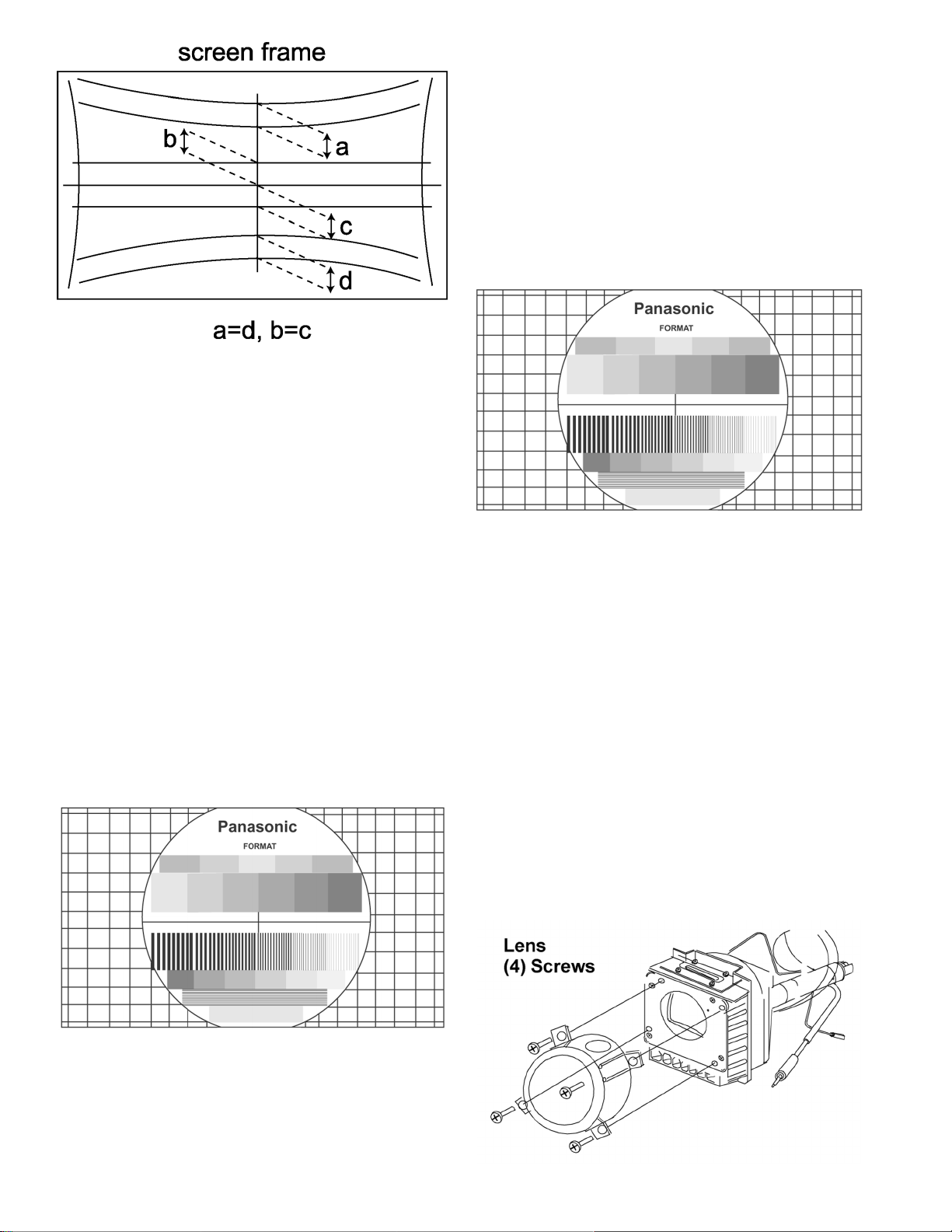
14.6. Pincushion adjustment (PCC)
This adjustment is intended to correct curved sides of the
picture.
NOTE:
1080i, 480p, 480i pattern can be obtained from Panasonic’s
TU-DST51 set-top box DTV decoder.
Procedure:
1. Apply a pattern that lets adjust the image to correct curved
sides (see above note)
2. Set VIDEO “C_OFF” DAC from 00 to 01 to project only
green.
3. Set DAC “MUTE” from 00 to 01 (disabling digital
convergence)
4. If the distance at “A” isnot 10 ± 5mm, enter H DEF “H WID”
DAC and adjust by VOLUME UP/DOWN until it is 10± 5mm.
14.5. Horizontal size adjustment
(H_POS)
This adjustment is intended to correct the horizontal position of
the picture.
Pincushion adjustment
24
5. If not all corners of cross hatch appear in screen, enter V
DEF “V-AMP” DAC and adjust until they appear.
6. Confirm that measurement of “A” has not changed.
7. Enable digital convergence by changing DAC MUTE from
01 to 00.
8. Set VIDEO “C_OFF” DAC from 01 to 00.
5. Apply an HD 1080i signal and repeat this adjustment for
HD 1080i mode
6. To check ABL apply a white pattern and put user bright
control (BRIGTHNESS in Picture menu) control to max.
and confirm that reading on meter is 12.7 ± 0.8V.
14.10. Individual ABL Check (I-ABL)
14.7. Trapezoid adjustment (TRAP)
NOTE:
1080i, 480p, 480i pattern can be obtained from Panasonic’s
TU-DST51 set-top box DTV decoder.
Procedure:
1. Apply a crosshatch pattern.
2. Enter service mode, select “TRAP” and adjust DATA with
VOLUME keys in remote so that lines at right and left are
vertical like a solid line.
14.8. Horizontal size adjustment (H
WID)
This adjustment is intended to adjust horizontal width of the
picture.
NOTE:
1080i, 480p, 480i pattern can be obtained from Panasonic’s
TU-DST51 set-top box DTV decoder.
1. Apply a pattern that lets adjust the horizontal size.
2. Set VIDEO “C_OFF” DAC from 00 to 01 to project only
green.
3. Set DAC “MUTE” from 00 to 01 (disabling digital
convergence).
4. In service mode, adjust “H WID” DAC until the picture
horizontal size is balanced at left and right side of screen.
5. Set DAC “MUTE” from 01 to 00 (disabling digital
convergence).
6. Set VIDEO “C_OFF” DAC from 01 to 00.
14.9. Sub-Bright adjustment
(BRIGH) and ABL check
This adjustment is intended to set 7 IRE signal to black level
mode.
Procedure:
1. Set PICTURE MODE TO VIVID, PICTURE settings to
normal, NATURAL COLOR to OFF and COLOR
TEMPERATURE to NORMAL.
2. Connect meter (positive lead) to D31 pin 2 and
(negative lead) to D31 pin 1.
3. Apply a color bar with no color or if available a grey
levels pattern.
4. Adjust DAC “BRIGH” data so that bar near to black bar
becomes near black
Procedure:
1. In PICTURE menu set the picture to “NORMAL”.
2. Apply a pure blue flat signal from a signal generator or
another source.
3. In service mode select “I-ABL” DAC from service menu.
4. Confirm that the 3 hex values that appear on screen
(below the “I-ABL” label) are close to 0, i.e. “00 00 00”
5. If the “I-ABL” values differ too much from 0, repeat
bright and ABL adjustment again.
14.11. Red, green & blue screen CutOff
1. Use either a no input signal condition or raster from the
NTSC generator.
2. Observing the green tube directly or viaa reflective surface,
adjust the VR on focus pack for the green tube for minimum
noise.
3. Adjust the noise level in the redand blue tubes to match the
noise level in the green tube.
14.12. White balance adjustment
NOTE:
1080i, 480p, 480I pattern can be obtained from Panasonic’s
TU-DST51 set-top box DTV decoder.
Prior to this adjustment, perform sub-contrast adjustment. This
adjustment requires the service user skills in observing what a
screen without color should look like (white picture).
Preparation:
1. Set the following in the user picture menu as follows:
· PIC MODE to VIVID
· COLOR to center (31)
· PICTURE to max (63)
· BRIGHT to center (31)
· SHARPNESS to min. (0)
· TINT to center (31)
· NATURAL COLOR to OFF
· COLOR TEMPERATURE to COOL
1. Enter the service mode.
2. Apply a black and white pattern to one of the video inputs
(see above note) color bar with no color.
14.12.1. High light white balance
adjustment
1. Adjust DAC R_DR for red and B_DR for blue adjustments.
2. Make sure the screen is not blue or green. The screen
should be white in the white area.
3. Check the black and white area for a black and white
picture with even shades of gray and no color tint in the
25
picture.
14.12.2. Low light white balance
adjustment
1. Adjust DAC CUT_R for red and DAC CUT_B for blue.
2. Check the screen for even white in all areas, no color.
3. Check the black and white pattern for a black and white
picture, even shades of gray and no color tint in the low light
areas.
4. Repeat the high light and low light white balance again until
the white balance tracks from high light to low light.
6. Use a test signal from a VCR or laser disk that has a
pre-recorded close up of a signal that has good flesh
tones.
7. The signal on the VCR or laser disk should look normal.
Color Check
Using a clean RF or video signal, set the color level so that
it does not saturate or appear harsh. Make sure that color
is not set so that it appears dull and washed out. Look for
natural colors, try to adjust the picture to appear as a
normalphotograph.
14.15. Clock Adjustment (CLOCK)
14.13. Color adjustment (TINT, BY_G, R-Y_A)
NOTE:
1080i, 480p, 480i pattern can be obtained from Panasonic’s
TU-DST51 set-top box DTV decoder.
This adjustment requires that the servicer use the skills in
observing what a colorbar pattern should looks like.
Preparation:
1. Set the following in the user picture menu as follows:
· PIC MODE to VIVID
· COLOR to center (31)
· PICTURE to max (63)
· BRIGHT to center (31)
· SHARPNESS to min. (0)
· TINT to center (31)
· NATURAL COLOR to OFF
· COLOR TEMPERATURE to COOL
Procedure:
1. Apply a color bar pattern
2. Adjust DAC “TINT” so that the fourth bar from right to
left becomes purple and good color balance.
3. If the adjustment is high, the bar will look pinkish, if it is
low will look bluish.
4. Adjust “B-Y_G” so blue look natural, and the rest of the
colors become in balance.
5. Adjust “R-Y_A” so red look natural, and rest of the
colors become in balance.
6. Check that white bar is real white, no bluish or reddish
or tending to become grey.
Preparation:
Connect the frequency counter from TP0PLL (A-Board
Connector A31 pin 56) to cold ground.
Note:
Frequency Counter probe capacitance should be 8pF or
less.
Procedure:
1. Turn the PTV “ON” with the A.C. power applied.
2. Measure TP0PLL (A-Board Connector A31 pin 56)
for frequency and record the reading.
Note:
Pin measurement must have at least four digits
of resolution following the decimal point.
Example: 000.0000
3. Place the PTV into service mode for making
electronic adjustment, select the clock adjustment
DAC CLOCK and change value to 128.
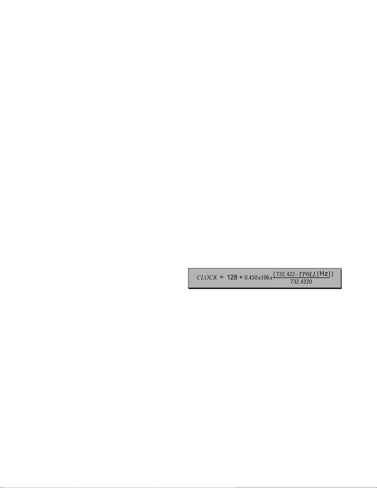
4. Calculate and set CLOCK based on the following
formula:
Note:
TP0PLL measurement will not change
regardless of the value stored in CLOCK.
14.14. Tint and color check
Set picture mode to VIVID mode. Again, the service ability to
see color and the balance of color is important for theses
adjustments.
Tint check
1. In picture menu set PICTURE NORMAL to YES.
2. Apply color bars to the video input.
3. Magenta is composed of two colors, blue and red.
4. Check to see that magenta does not have too much
blue or too much red.
5. Check cyan. Cyan is composed of blue and green. It
should not have too much blue or green.
26

14.16. Receiver Firmware Upgrade
1. First check that receiver is operating out of service mode
(normal use).
IMPORTANT:
For better results in this procedure, be sure that the set
is already powered ON and if the set is powered OFF,
wait at least 10 seconds after turning ON the receiver
before inserting the SD service card to the service slot.
2. Check the current software version of receiver by pressing
on front panel the next sequence rapidly:
VOLUME UP and MENU buttons at the same time, then
CHANNEL UP and MENU buttons at the same time.
3. A status screen will appear displaying information about the
System.
4. The “System” information displays the current software
version of the receiver along with the release date.
5. Insert the SD service card in the back of the receiver in the
slot with a sign “SERVICE ONLY”.
6. The receiver will automatically display a screen, showing
the current software version of the receiver (right) and the
software version stored in the SD service card (left), (i.e.
ROM Ver: 00010306 indicates that current ROM version is
1.3.6.). In case that receiver doesn’t show this screen enter
service mode, display the service menu by pressing
POWER on the remote and select “SD_DL” DAC register.
7. Press OK button on the remote to start the software
upgrade on the receiver.
IMPORTANT!:
ONCE THAT DOWNLOADING PROCESS HAS
BEGUN IT CANNOT BE CANCELLED. DURING
SOFTWARE DOWNLOADING DO NOT DISCONNECT
THE AC PLUG FROM OUTLET!!, THIS COULD
RESULT IN A PERMANENT DAMAGE TO THE
SERVICE CARD AND TO THE RECEIVER AS WELL.
8. Once that the download is complete a screen appears with
the next instructions:
a. Remove the SD card from the back of the TV set.
b. Disconnect the power cable from the wall outlet.
c. Reconnect the power cable to the wall outlet.
9. Press POWER on the receiver to turn ON.
10. Check the current software version of receiver by pressing
on front panel the next sequence rapidly:
VOLUME UP and MENU buttons at the same time, then
CHANNEL UP and MENU buttons at the same time.
11. Press EXIT to clear the screen and go back to normal use
mode.
14.17. JPEG Viewer Software
Upgrade
1. With the receiver powered ON, insert the SD service card in
the front panel slot, then automatically, a download menu
will appear. If the download menu doesn’t appear. Enter
service mode, display the service menu by pressing
POWERon the remote and select “JPEG” DAC register.
Select option No. 6 with CH keys to acces the “JPEG
Program Download” menu.
NOTE:
To abort the download process just press “EXIT” on
remote in the “JPEG Program Download” menu.
IMPORTANT:
For better results in this procedure, be sure that the set
is already powered ON and if the set is powered OFF,
wait at least 10 seconds after turning ON the receiver
before inserting the SD service card to the JPEG viewer
slot.
2. Select the newest version of software with CH keys, then
press OK.
3. A confirmation sign appears asking if the selected version
wants to be downloaded, then with VOL keys select “YES”
and press OK to start downloading.
IMPORTANT!:
ONCE THAT DOWNLOADING PROCESS HAS
BEGUN IT CANNOT BE CANCELLED. DURING
SOFTWARE DOWNLOADING DO NOT DISCONNECT
THE AC PLUG FROM OUTLET!!, THIS COULD
RESULT IN A PERMANENT DAMAGE TO THE
SERVICE CARD AND TO THE RECEIVER AS WELL.
4. Once the downloading is finished, disconnect the AC plug
from outlet then remove the SD service card from the slot.
5. Connect again the AC plug to the outlet and turn power ON.
6. Press both OK and POWER buttons on the receiver’s front
panel to access to the self-check screen and wait a few
seconds.
7. If the JPEG module is working accordingly, a “JPEG OK”
sign will appear and within, the last upgrade version of the
JPEG viewer software, i. e. “JPEG OK : 01.00.04” .
8. Press any key to exit the self-check screen or unplug AC
cord to completely reset.
14.18. JPEG Factory and Service
Mode (JPEG)
1. Enter service mode, and with the SD service card already
inserted (JPEG viewer slot), from the service menu select
“JPEG” DAC register.
2. A screen displaying the “JPEG Factory and Service Mode”
menu will appear with 6 options and at the bottom the
current JPEG software version.
3. To select one of the options press the CH keys on remote.
4. Option No. 1 will perform an auto test from option No. 2
trough No. 5.
· SDRAM Test: will perform a test of the internal memory
of the JPEG reader device, showing for a few seconds
a green screen followed by a magenta screen. If the test
is succesfull an OK flag will appear on menu.
· Color bar Test: this will perform a color display test in
the JPEG reader device showing in the screen a color
rainbow bar pattern at the top and a black and white
pattern at the bottom. If the colors are shown correctly
the JPEG color driveris working properly. Press exit on
remote to go back to service menu.
· SD Card Test: this will perform a JPEG picture reading
test on the SD Card. The SD card inserted must have
pictures with JPEG format to pass the test.
27

· PC Card Test: this will perform a JPEG picture reading
test on the PC Card. The PC card inserted must have
pictures with JPEG format to pass the test.
· Download: enters to the “JPEG Program Download”
menu.
5. Press EXIT to go back to service mode.
14.19. CableCARD check
1. First check that receiver is operating out of service mode
(normal use).
2. Insert the CableCARD (POD).
3. Check that the fan on the back of the set should be turned
ON.
IMPORTANT:
If the fan is disconnected accidentaly or if the fan is
damaged and it’s not turned ON when the module is
inserted, the PTV will automatically be set in protection
mode and it will shut down. Connect again the fan
correctly or replace itwith a new one (for order number
see parts list section) and press power to turn ON.
4. A sign on the screen with instructions should appear
indicating that the CableCARD has been inserted.
5. Check the current software version of receiver by pressing
on front panel the next sequence rapidly:
VOLUME UP and MENU buttons at the same time, then
CHANNEL UP and MENU buttons at the same time.
6. A status screen will appear displaying information about the
System status.
7. The “System” information displays the current software
version, release date, memory and POD status.
8. If the CableCARD is operating properly the POD status will
indicate that the CableCARD is present. If the CableCARD
is inserted and the POD status indicates that is not present,
the CableCARD could be damaged.
9. To exit the system status screen, press exit.
10. Remove the CableCARD and check that a sign on the
screen appears indicating that the card has been removed.
28
15 Convergence adjustment
Turn PTV on and allow it to warm up for 30 minutes prior to
perform adjustments (apply a WHITE PATTERN).
Helpful Hint:
EEPROM jig can be used to adjust convergence, by
copying convergence adjustment from a convergence
adjusted PTV to other. Refer to EEPROM copy jig section
on this service manual. Also EEPROM copy jig can be used
to back-up the data before to performadjustments.
NOTE:
1080i, 480p, 480i pattern can be obtained from Panasonic’s
TU-DST51 set-top box DTV decoder.
IMPORTANT NOTICE:
It is strongly recommended to first read and understand the
following section prior to make any adjustment.
This PTV uses the scheme described below to correct for
misconvergence of the three CRT projection tubes. There are
various modes to this operation.
Preparation:
Place the convergence alignment template (see
Convergence alignment template section on this manual)
over the PTV screen. Align the center lines of the template
with the mechanical center markers on the PTV screen
frame. If the template is not available,create one using the
dimensions provided in Convergence alignment template
section on this manual.Remote control must be used during
the procedure.
Procedure:
Apply the convergence alignment template to the PTV
screen frame to converge the green raster only. Remove
the convergence alignment template following this
alignment. The red and blue rasters can then be aligned to
the green raster.
Raster Set-Up:
1. Enter to service mode (red CHK).
2. In SET-UP (menu) enter to “Other Adj.” menu and set
CONVERGENCE values (GH, GV) to 0.
3. Cover red & blue lens with caps.
4. Apply a pattern to adjust with 1080i HD format:
5. Select “COARSE” DAC, then press OK to enter to
“Coarse adjustment” mode.
6. Press “0” key on remote.
7. Press OK key on remote to enter to “TEST_POS” mode.
8. Move pattern by pressing VOL right - left and CH up down so that the cursor center overlap monoscope
pattern center.
Aligned cross-hair pattern with center of picture pattern
9. Press “5” key on remote to exit superimpose mode
(monoscope pattern disappear).
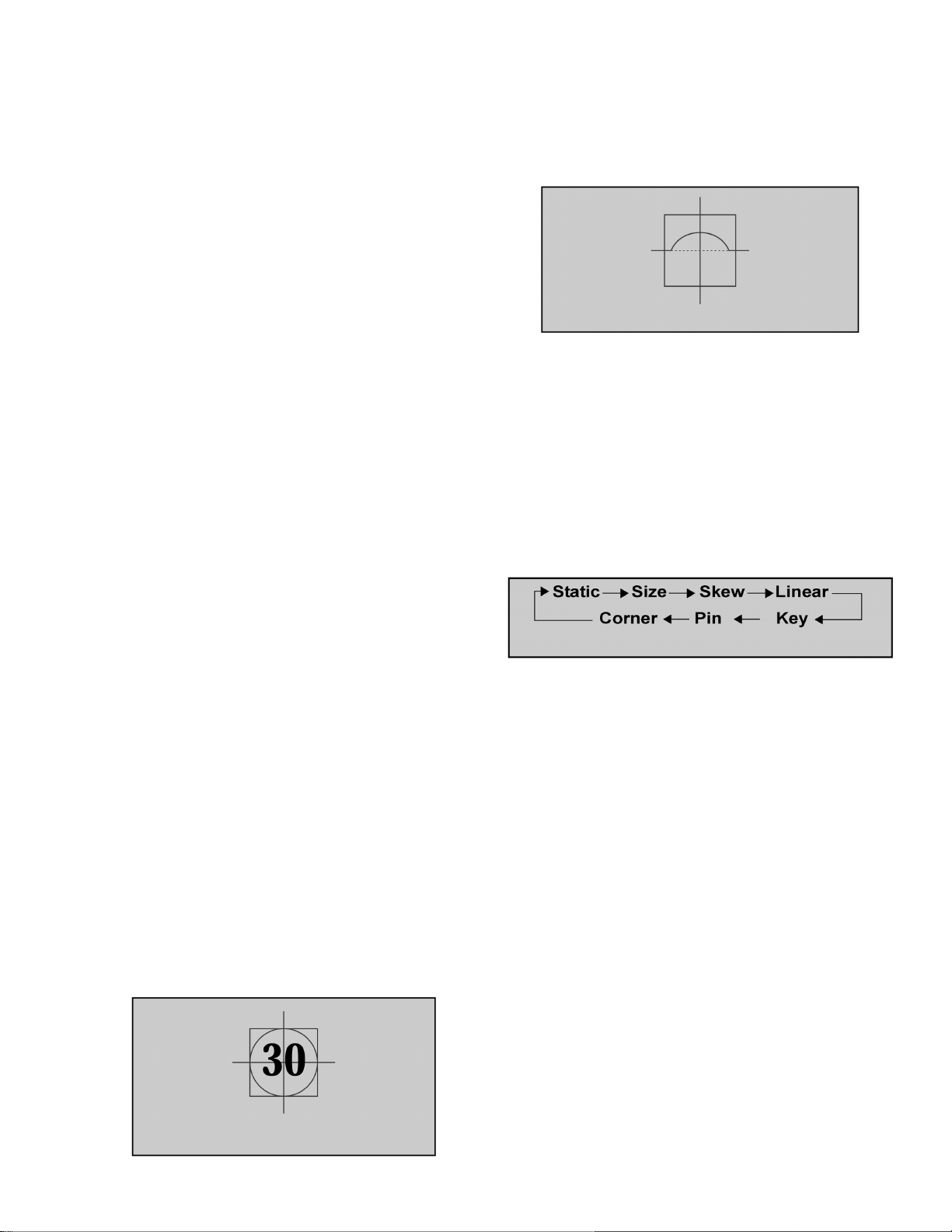
10. Press “TV/VIDEO” key to enter “DATA_POS” mode
11. Adjust by pressing VOL right - left so that peak of curve
is the same position as center of cursor.
Symmetrical shape
12. Press “TV/VIDEO” key on remote to enter “OSD_POS”
mode.
13. Press “5” key on remote so that monoscope pattern
appears (superimpose mode)
14. Move cursor by pressing VOL right - left and CH up down so that cursor center overlap monoscope pattern
center
15. Press “0” key to go back to “Coarse adjustment” mode.
16. Press “TV/VIDEO” key to cycle through “Coarse
adjustment” options
“COARSE” modes cycle
17. To change to “Fine Adjustment Mode” options (“FINE”
DAC), press “TV/VIDEO” key on remote for at least 3
seconds, to go back to “Coarse
Adjustment Mode” options press “TV/VIDEO” on remote
again for 3 seconds.
18. In “Fine Adjustment Mode” options, press “MUTE” key
on remote to switch between “cursor” mode and “data”
mode.
· Cursor mode: Allows cursor movement by pressing
VOL right - left and CH up - down.
· Data mode: Allows making adjustment by pressing
VOL right - left and CH up - down.
19. Either “Coarse Adjustment” options or “Fine Adjustment”
options, press “R-TUNE” repeatedly key on remote to
cycle through different color adjustments (R, G, B,
White)
20. In “Fine Adjustment” options, press “4” key on remote to
ADD crossed sections to pattern and make effect visible
between crossed sections.
21. To store adjustments press “7”, then “OK” key on
remote, otherwise press “POWER” then “OK“ to exit
adjustments without saving.
22. Once out of the “COARSE” register, “AUTO OFFSET”
process begins by comparing red, green and blue color
adjustment with the internal PTV convergence sensors.
29
 Loading...