

Panasonic PT-47WX52F, PT-47WX52CF, PT-47WX42F, PT-47WX42CF Service Manual
ORDER NO. MTNC020409C1
B2
Service Manual
HDTV MONITOR
Main Manual
(P7W)
Panasonic
Models
Chassis
PT-47WX52F EP824
PT-47WX52CF EP824
PT-47WX42F EP824
PT-47WX42CF EP824
This service manual is issued as a service guide for the models of the P7W family listed above. Included in this
manual are a set of schematics, alignment procedures, disassembly procedures and a complete parts list.
“WARNING! This ServiceManualis designed for experiencedrepairtechniciansonly and is not designed for useby the generalpublic.
It does not contain warnings or cautions to advise non-technical individuals of potential dangers in attempting to service a product.
Products powered by electricity should be serviced or repaired only by experiencedprofessional technicians. Any attempt to
service or repair the product or products dealt with in this Service Manual by anyone else could result in serious injury or death.”
The service technician is requiredtoreadand follow the “Safety Precautions”and“Important Safety Notice” in the Main Manual.
Copyright 2002by Matsushita Electric Corporation of
America. All rights reserved. Unauthorized copying
®
and distribution is a violation of law.
Important safety notice
Special components are used in this projection television which are important for safety. These components are
identified on the schematic diagram by the symbol and printed in BOLD TYPE on the replacement part list. It is
essential that these critical parts are replaced with the manufacturer’s specified replacement part to prevent x-ray
radiation, shock, fire or other hazards. Do not modify the original design without the manufacturer’s permission.
Safety precautions
General guidelines
An
isolation transformer
during the servicing of a PTV whose chassis is not
isolated from AC power line. Use a transformer of
adequate power rating as this protects the technician
from accidents resulting in personal injury from
electrical shocks. It will also protect the PTV from being
damaged by accidental shorting that may occur
during servicing.
When servicing, observe the original lead dress,
especially in the high voltage circuit. Replace all
damaged parts (also parts that show signs of
overheating.)
Always replace protective devices,suchas
fishpaper, isolation resistors and capacitors, and
shields after servicing the PTV. Use only
manufacturer’s recommended rating for fuses, circuits
breakers, etc.
High potentials, as high as 32.5kV, are present when
this PTV is operating. Operation of the PTV without the
rear cover introduces danger for electrical shock.
Servicing should not be performed by anyone who is
not thoroughly familiar with the necessary precautions
when servicing high-voltage equipment.
Extreme care should be practiced when handling the
picture tube
due to atmospheric pressure. (14.7 lbs. per sq. in.). Do
not nick or scratch the glass or subject it to any undue
pressure. When handling, use safety goggles and
heavy gloves for protection. Discharge the picture
tube by shorting the anode to chassis ground (not to
the cabinet or to other mounting hardware). When
discharging connect cold ground (i.e. DAG ground
lead) to the anode with a well insulated wire or use a
grounding probe.
. Rough handling may cause it to implode
X-ray precautions
The front area (between the projection tube and the
lens) is enclosed by a metal box t o ensure positive
safety during normal and abnormal conditions when
checking and repairing. To fully ensure safety, the
following precautions must be observed.
1. Do not remove the lens or metal box.
2. Make sure to turn the power OFF when the lens is
removed or when checking the cleanliness of the
lens.
3. Do not remove the lens or metal box to check the
projection tube for operation by watching it directly.
Use a mirror or paper to view the image.
Before returning a serviced PTV to the owner,the
service technician must thoroughly test the unit to
ensure that is completely safe to operate. Do not use a
line isolation transformer when testing.
Leakage current cold check
Unplug the AC cord and connect a jumper between the
two plug prongs. Press the POWER switch ON.
Measure the resistance between the jumpered AC plug
and expose metallic parts such as screw heads,
ServiceManual
should always be used
antenna terminals, control shafts, etc. If the exposed
metallic part has a return path to the chassis, the
reading should be between 240kΩ and 5.2MΩ. If the
exposed metallic part does not have a return path to
the chassis, the reading should be infinite.
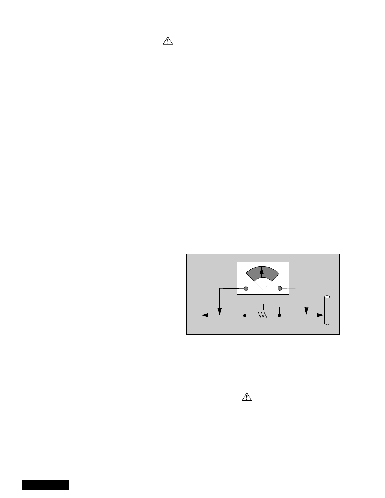
Leakage current hot check (see figure 1)
Plug the AC cord directly into the AC outlet. Do not use
an isolation transformer during the check.
Connect a 1.5kΩ 10 watt resistor in parallel with a
0.15µF capacitor between and exposed metallic part
and ground. Use earth ground, for example a
water pipe.
Using a DVM with a 1000 ohms/volt sensitivity or
higher, measure the AC potential across the resistor.
Repeat the procedure and measure the voltage
present with all other expose metallic parts.
Verify any potential does not exceed 0.75 volt RMS. A
leakage current tester (such a Simpson model 229,
Sencore model PR57 or equivalent) may be used in
the above procedure, in which case any current
measure must not exceed 0.5 milliamp. If any
measurement is out of the specified limits, there is a
possibility of a shock hazard and the PTV must be
repaired and rechecked before it is returned to
the customer.
AC VOLTMETER
COLD
WATER
PIPE
(GROUND)
0.15µF
TO INSTRUMENT’S
EXPOSED METAL
PARTS
Figure 1. Hot check circuit
1500Ω,10W
Insulation test
Connect an insulation tester between an exposed
metallic part and AC line.
Apply 1080VAC/60Hz for 1 second. Confirm that the
current measurement is 0.5mA ~ 2.0mA. Repeat test
with other metallicexposed parts.
X-ray radiation
WARNING: The potential source of x-ray radiation in the
PTV is in the high voltage section and the picture tube.
Note: It is important to use calibrated equipment.
Apply all black video signals (1080i) and confirm high
voltage measures 31.5 ± 1.0kV. If the high voltage is
not within the range, change C514 to 1800pF, 2000pF,
2400pF or 2700pF until the desired value is obtained.
Apply NTSC white pattern and confirm the high voltage
measures 30.1 ± 1.5kV.
Apply HD 1080I white pattern and confirm the high
voltage measures 30.1 ± 1.5kV
-2-
About lead free solder (PbF)
component
Note: Lead is listed as (Pb) in the periodic table of elements.
In the information below, Pb will refer to Lead solder, and PbF will refer to Lead Free Solder.
The Lead Free Solder used in our manufacturing process and discussed below is (Sn+Ag+Cu).
That is Tin (Sn), Silver (Ag) and (Cu) although other types are available.
This model uses Pb Free solder in it’s manufacture due to environmental conservation issues. For
service and repair work, we’d suggest the use of Pb free solder as well, although Pb solder may be
used.
PCBs manufactured using lead free solder will have the PbF within a leaf symbol stamped on the
back of PCB.
Caution
• Pb free solder has a higher melting point than standard solder. Typically the melting
point is 50 ~ 70 °F(30~40°C) higher. Please use a high temperature soldering iron
and set it to 700 ± 20 °F(370± 10 °C).
• Pb free solder will tend to splash when heated too high (about 1100 °For600°C).
If you must use Pb solder, please completely remove all of the Pb free solder on the
pins or solder area before applying Pb solder. If this is not practical, be sure to heat the
Pb free solder until it melts, before applying Pb solder.
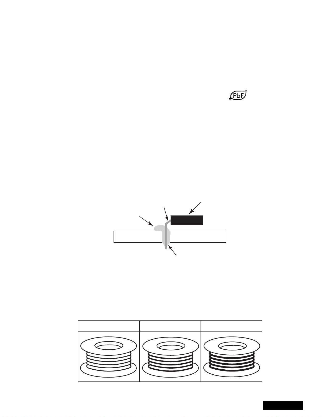
• After applying PbF solder to double layered boards, please check the component side
for excess solder which may flow onto the opposite side. (see figure below)
component
remove all of the
excess solder
pin
slice view
solder
Suggested Pb free solder
There are several kinds of Pb free solder available for purchase. This product uses Sn+Ag+Cu
(tin, silver, copper) solder. However, Sn+Cu (tin, copper), Sn+Zn+Bi (tin, zinc, bismuth) solder
canalsobeused.
0.3mm X 100g
0.6mm X 100g 1.0mm X 100g
-3-
ServiceManual
Important safety tests
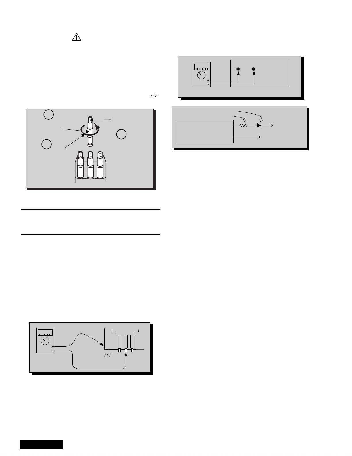
Measuring H.V.
The anode caps are cemented to the CRTs. To gain
access for high voltage measurement, remove the red
CRT’s anode lead from the flyback transformer
distributor. Grasp the anode lead protective cap at its
bottom and squeeze it against the locking cap body
inside, rotate 1/4 turn counter clockwise and pull the
anode lead sleeve out of the FBT distributor. Connect a
high voltage lead (+) from your H.V. meter to the FBT
distributor, and the common (-) to cold ground ( ).
(see figure 2).
1
Grasp protective
Anode lead
rubber cap
3
2
Push & rotate
Discharge to
CRT chassis
cap counterclockwise
to remove
FBT distributor
Figure 2. Removal of FBT leads
Note: Reinsert the anode lead into the FBT
distributor until it is tightly and fully seated.
Turn the locking cap clockwise to lock in place.
(EHT) Protector operation check
With the cabinet back removed, apply a nominal 120V
AC to the PTV.
Over voltage test
Preparation:
1. Turn PTV “OFF”
2. Connect a NTSC signal generator to the
antenna terminal.
3. Connect DVM (+) TPD50 and (-) TPD51 on
D Board (see figure 4)
4. Connect a H.V. meter (static type, class 0.1) with
high voltage leads to high voltage distributor
on FBT. (See figure 4)
TPD51 TPD50
-
+
D-Board
DVM
D-Board
IC802 PIN 2
OR TPD8
Variable
power
supply
MA150
100Ω 1/2 W
(+)
(15~25DC)
(-)
HEAT SINK OF Q551
Figure 4. DVM & power supply c onnection.
5. Connect the 15 ~25 VDC variable power supply to
(+) TPD8 or IC802 pin 2 (D-Board) and (-) heat
sink of Q551 (see figure 4).
Procedures:
1. Apply a NTSC white pattern.
2. Turn PTV ON.
3. Adjust the picture or brightness controls so that the
DVM reads 12.4 volts ±0.4 volts.
4. Increase the variable power supply until set turns
off. The set should turn off at 12.4 volts ± 0.4 volts
(DVM) and high voltage less than 36.4kV.
5. If the DVM reading is other than 12.4 volts (± 0.4
volts), readjust picture or brightness control and
repeat steps 3.
6. Turn off the variable supply and confirm that the set
will turn on with the remote control.
-
+
H.V. METER
ServiceManual
Cold ground
FBT Distributor
CRT
CHASSIS
Figure 3.Measuring H.V.
-4-

About format aspect switching(WX 16:9 or HX 4:3)
Widescreen 16:9 and non-widescreen 4:3 PTVs use the same
light box, for this reason is important to set it to the correct
version (16:9 or 4:3). To change the format please refer to
figure 62 on page 43.
Be sure to select the correct format for the serviced PTV.
-5-
ServiceManual
Importantsafetynotice...................2
Safetyprecautions........................2
Generalguidelines..................2
X-rayprecautions ..................2
Leakagecurrentcoldcheck...........2
Leakagecurrenthotcheck ...........2
Insulationtest .....................2
X-rayradiation.....................2
About lead free solder (PbF) . . . . . . . ........3
SuggestedPbfreesolder............3
Importantsafetytests....................4
MeasuringH.V.....................4
(EHT) Protector operation check. . . . . . . 4
About format aspect switching. . . . . ........5
Servicenotes ...........................7
Leadless chip component . . . . ........7
Componentremoval ................7
Chip component installation . . ........7
HowtoreplaceFlat-IC...............7
Featuretable............................9
Boardsdesignation.....................10
PTV-Locationofcontrols................11
Quick reference control operation . . . . . 11
Remote-Locationofcontrols.............12
Auto diagnosis feature. . . . . . . . . . . . .......14
A-Boardcheckpoints ...................15
A-Board check points waveforms. . . .......16
Chassis&boardslayout.................17
Boarddescription..................17
Disassemblyforservice .................18
Speakergrilleremoval..............18
Keyboardremoval.................18
Speakersreplacement..............18
Cabinet back lower cover removal . . .. 18
Cabinetbackcoverremoval.........18
Mirrorremoval....................18
Screenframeremoval..............19
Screenassembly..................19
Mainchassisblock ................19
Chassisassembly.................19
Disassembly for CRT replacement . . . . 20
CRTreplacement .................20
Optical block position adjustment . . . . . 21
PTVscreenassemblies.............22
B+voltagestable..................22
CRTsetup.............................23
Dynamicfocusadjustments..........23
Electricaladjustment...............23
Focus - Optical lens adjustment . . . . . .24
Opticaladjustments................24
NTSC Vertical size adjustment (VSIZE) 25
HD 1080i Vertical size
adjustment(VSIZE).............25
NTSC ZOOM Vertical size
adjustment(VSIZE).............26
NTSC Horizontal phase
adjustment(H-POS)............26
HD 1080i Horizontal phase adjustment
(H-POS) .....................26
Trapezoid adjustment (EWTRA) . . . . . . 26
NTSC Pincushion adjustment (PCC). . .26
HD 1080i Pincushion
adjustment(PCC)..............27
Centering magnets adjustment . . . . . . .27
NTSC Horizontal size
adjustment(HWID).............27
HD 1080i Horizontal size adjustment
(HWID)......................27
Convergenceadjustment............27
Coarse adjustmentmode (COARSE) . .29
Fine adjustment mode
(FINE)(convergence)...........30
Horizontal and vertical size check . . . . .33
Convergence alignment template . . . . . 33
Service mode (electronic controls). . . . . . . . . 34
Quickentrytoservicemode.........34
To toggle between aging
andservicemodes.............34
Exitingtheservicemode............34
Tocheckcolors...................34
Table of the service adjustments
items available for each format . . . . 35
480iServicemodeDACs ...........37
480pServicemodeDACs...........39
1080iServicemodeDACs ..........41
Instructional flow chart for format
aspect switching
(WX16:9orHX4:3)............43
Instructional flow chart for
servicemode..................44
NTSC Sub-Bright
adjustment(BRIGHT)...........46
1080i Sub-Bright
adjustment(BRIGHT)...........46
NTSC Color adjustment
(TINT,B-Y_G,R-Y_A) ..........46
1080i Color adjustment
(TINT,B-Y_G,R-Y_A) ..........46
Red, green & blue screen cutoff . . . . . .47
Whitebalanceadjustment...........47
Tintandcolorcheck ...............47
MTScircuitadjustments ............47
Inputleveladjustment(MTSIN).......47
Stereo separation adjustment
(SEPAL&SEPAH).............47
ClockAdjustment(CLOCK)..........48
Audiosignalpathblockdiagram ..........49
Video-chroma signal path block diagram . . . 50
IICconnection..........................51
Description of connectors. . . . ............52
Partslist ..............................53
Schematics........................66~103
ServiceManual
-6-

Service notes
Note: These components are affixed with glue. Be careful not to break or damage any foil under the
component or at the pins of the ICs when removing. Usually applying heat to the component for
a short time while twisting with tweezers will break the component loose.
Leadless chip component
(surface mount)
Chip components must be replaced with identical chips
due to critical foil track spacing. There are no holes in
the board to mount standard transistors or diodes.
Some chip capacitor or resistor board solder pads may
have holes through the board, however the hole
diameter limits standard resistor replacement to 1/8
watt. Standard capacitor may also be limited for the
same reason. It is recommended that identical
components be used.
Chip resistor have a three digi t numerical resistance
code - 1st and 2nd significant digits and a multiplier.
Example: 162 = 1600 or 1.6kΩ resistor, 0 = 0Ω (jumper).
Chip capacitors generally do not have the value
indicated on the capacitor. The color on the component
indicates the general range of the capacitance.
Chip transistors are identified by a two letter code. The
first letter indicated the type and the second letter , the
grade of transistor.
Chip diodes have a two letter identification code as per
the code chart and are a dual diode pack with either
common anode or common cathode. Check the parts
list for correct diode number.
Component removal
1. Use solder wick to remove solder from component
end caps or terminal.
2. Without pulling up, carefully twist the component
with tweezers to break the adhesive.
3. Do not reuse removed leadless or chip
components since they are subject to stress
fracture during removal.
Chip component installation
1. Put a small amount of solder on the board
soldering pads.
2. Hold the chip component against the soldering
pads with tweezers or with a miniature alligator clip
and apply heat to the pad area with a 30 watts iron
until solder flows. Do not apply heat for more than
3 seconds.
TYPE
Chip components
GRADE
c
c
SOLDER
CAPS
How to replace Flat-IC
- Required tools -
• Soldering iron • De-solder braids
• Sharp pliers (wire
cutters and long nose)
1. Cut the pins of the defective IC with the wire cutter
pliers, and remove it completely away from the
board. If the IC is glued to the board, apply hot air
to complete the removal. CAUTION- Do not pull or
twist the pliers, it may damage the soldering pads
in the board .
Flat-IC
2. Using the soldering Iron and the long nose pliers,
remove the IC pins that are still attached to the
board.
3. Using the de-solder braid and the soldering Iron,
remove the solder from the board soldering pads.
4. Position the new flat IC in place (apply the pins of
the flat IC to the soldering pads where the pins
need to be soldered). Properly determine the
positions of the soldering pads and pins by
correctly aligning the polarity symbol. Start aligning
and soldering Pin No.1, then align and solder the
pin in the apposite corner of the IC, this will help to
align the rest of the pins.
Polarity
symbol
• Magnifier
Soldering
Iron
De-Solder
Braid
Soldering
Iron
b
b
ANODES
MH DIODE
e
e
TRANSISTOR
COMMON
CATHODE
SOLDER
CAPS
CAPACITOR
1ST DIGIT
RESISTOR
2ND DIGIT
MULTIPLIER
=1600 = 1.6k
5. Solder all pins to the soldering pads using a fine
tipped soldering iron.
Solder
Soldering
Iron
6. Check with a magnifier for solder bridge between
the pins or for dry joint between pins and soldering
pads. To remove a solder bridge, use a de-solder
braid as shown in the figure below.
De-Solder
Braid
-7-
Solder
Bridge
Soldering
Iron
ServiceManual

Service notes (continued)
IMPORTANT: To protect against possible damage to
the solid state devices due to arcing or static discharge,
make certain that all ground wires and CRT DAG wire
are securely connected.
CAUTION: The power supply circuit is above earth
ground and the chassis cannot be polarized. Use an
isolation transformer when servicing the PTV to avoid
damage to the test equipment or to the chassis.
Connect the test equipment to the proper ground (( )
or ( )) when servicing, or incorrect voltages will
be measured.
WARNING: This PTV has been designed to meet or
exceed applicable safety and x-ray radiation protection
as specified by government agencies and independent
testing laboratories.
To maintain original product safety design standards
relative to X-ray radiation and shock and fire hazard,
parts indicated with the symbol on the schematic
must be replaced with identical parts. Order parts from
the manufacturer’s parts center using the parts
numbers listed in this service manual, or provide the
chassis number and the part reference number.
For optimum performance and readability, all other
parts should be replaced with components of
identical specification.
ServiceManual
-8-
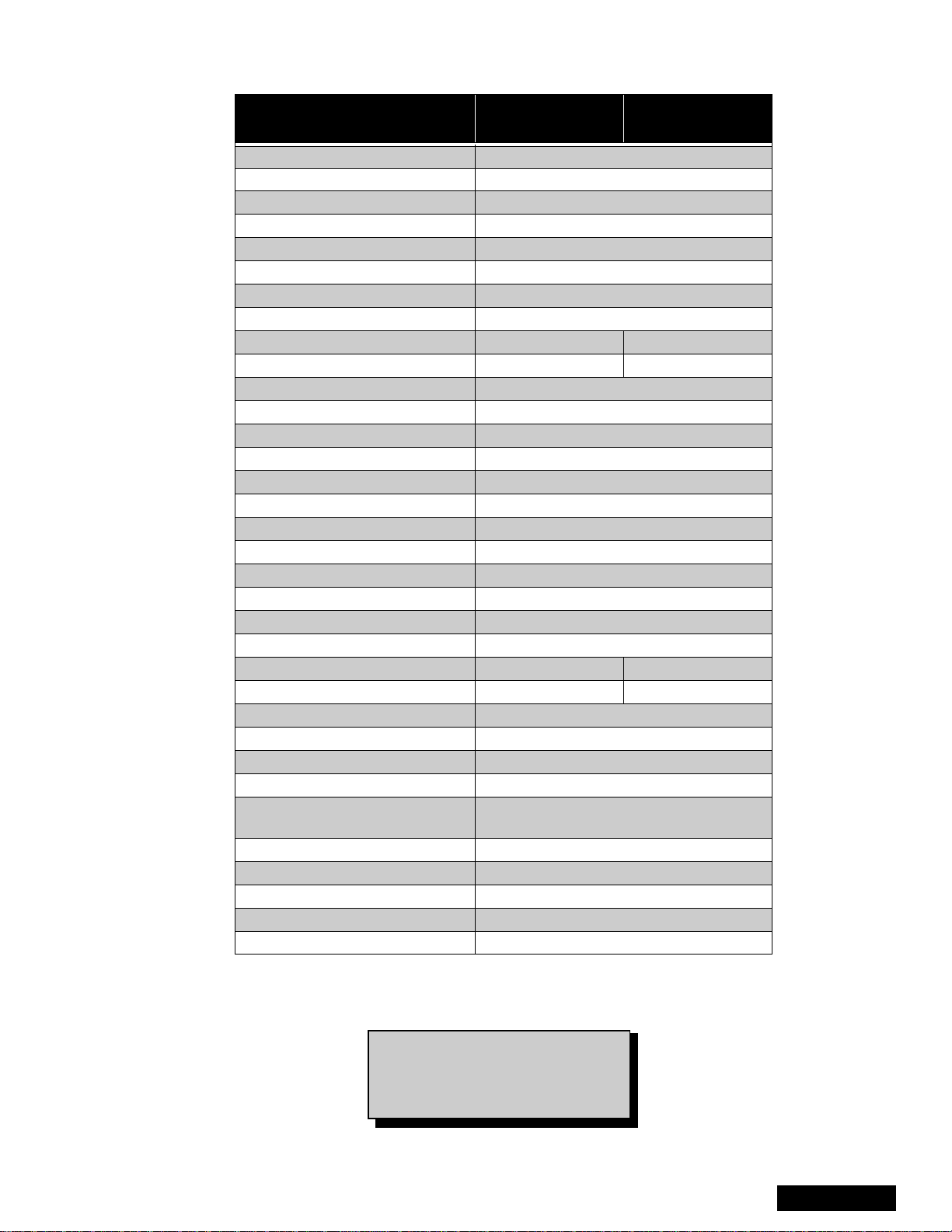
Feature table
FEATURE
Chassis P7W
Number of channels 181
Menu language Eng/Span/Fr
Closed caption (CC) X
V-Chip (USA/CANADA) X
Picture in Picture (PIP) 2T split
VIDEO INPUT MEMORY/SKIP SKIP
2RF X
Remote control number EUR7603Z30 EUR7603Z40
Screen protector W/PROT SCRN W/O PROT SCRN
Comb filter ADV 3D Y/C (NEW)
Color temp X
NEW YNR X
VM X (DIGITAL)
V/A norm X
DIGITAL SCAN RATE 1080i, 480p
NTSC LINE-DOUBLER 480p SMOOTH PROGRESSIVE
MTS/SAP/DBX X
Bass/Bl/Trebcontrol X
AI sound X
SURROUND X
Spatializer/BBE BBE
Built-in audio power 15WX2 (10%) 10WX2 (10%)
Number of speakers 4 2
A/V in (rear/front) 4 (3/1)
S-VHS in (rear/front) 2/1
Audio out Fixed & Variable
COMPONENT INPUT (Y, Pb, Pr) 2
Dimensions mm
WxDxH in
Weight (kg/lbs) 82/180.78
Power source (V/Hz) 120V 60Hz
Anode voltage 31.5kV ± 1.0kV
Video input jack 1Vp-p 75Ω,phono jack
Audio input jack 500mV RMS 47kΩ
PT-47WX52F
PT-47WX52CF
1111x1236x626
43.74x48.66x24.64
PT-47WX42F
PT-47WX42CF
Table 1: Feature Table
Specifications are subject to change
without notice or obligation.
Dimensions and weights are
approximate.
-9-
ServiceManual
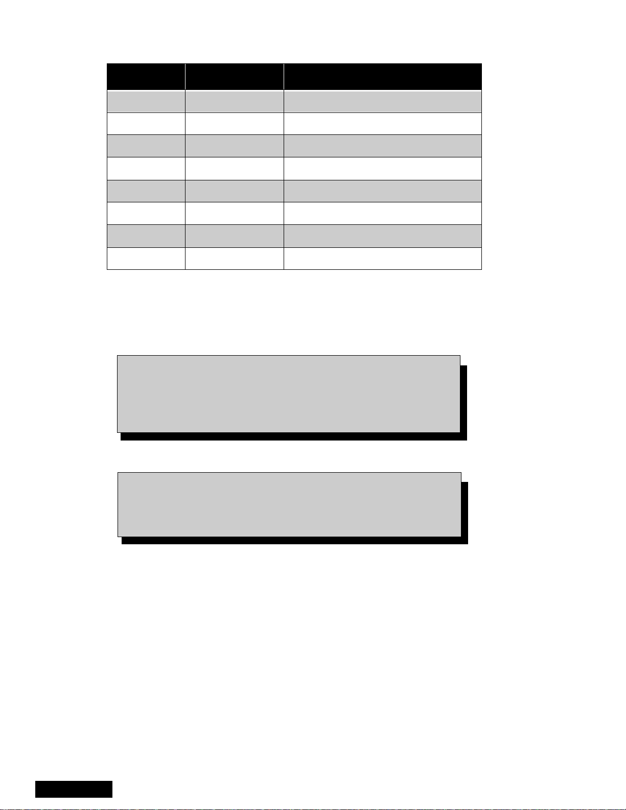
Boards designation
BOARD PART NUMBER BOARD DESCRIPTION
A-Board TNP2AH035 signal processing
D-Board TNPH0371 power and deflection
LB-Board TNP2AA110 blue driver
LG-Board TNP2AA111 green driver
LR-Board TNP2AA112 red driver
G-Board TNP2AA090 front A/V panel
K-Board TNP2AA089 front button panel
R-Board TNPA0615AB IR receiver
Table 2: Boards designation
Note: The A-Board (
A-Board both tuners, IC2302, IC7001, IC7002, IC871, IC872,
IC873. If any of these components or board is defective repleace
it with a new one and takeback the defective board tothe service
center.
Notice: When ordering any board, add and ” S” after the board
Example: If Order D-Board, should be ordered as:
TNP2AH035
suffix application.
) is non-serviceable.Exceptfor
TNPH0371
S.
ServiceManual
-10-
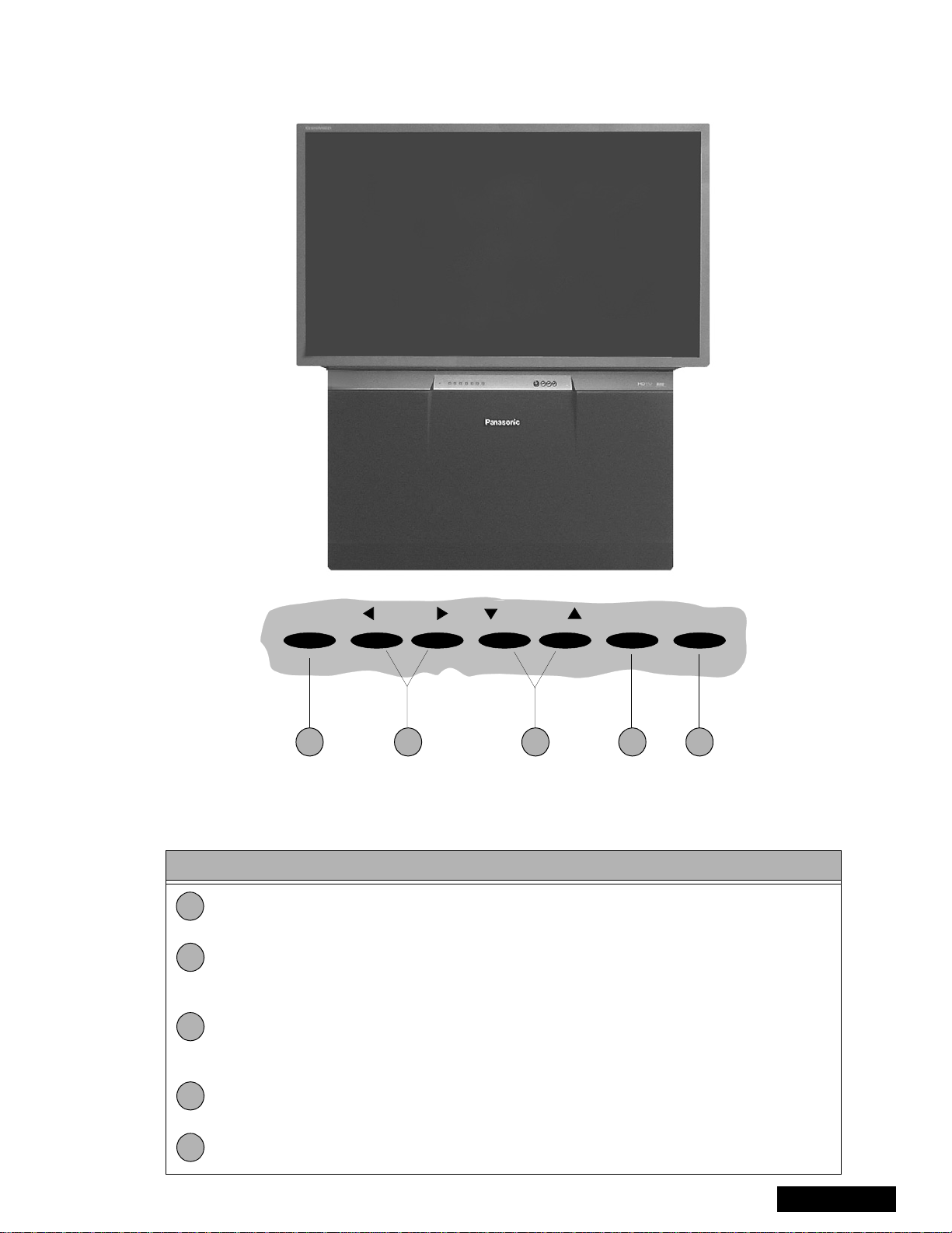
PTV - Location of controls
POWER VOLUME CHANNEL ACTION TV/VIDEO
1 2 4 53
Figure 5. Location of controls PTV
Quick reference control operation
Quick reference control operation
1
2
3
Power - Press to turn ON or OFF.
Volume - Press to adjust sound level, or to adjust audio menus, video menus, and
select operating features when menus are displayed
Channel - Press to select programmed channels. Press to highlight desired features
when menus are displayed. Also use to select cable converter box channels after
programming remote control infra-red codes (the TV/AUX/CABLE switch must be set
in CABLE position).
4
Action - Press to display main menu and access on screen feature and adjustment
menus.
5
TV/Video - Press to select TV or one of the video inputs, for the main picture or thePIP
frame (when PIP frame is displayed).
-11-
ServiceManual
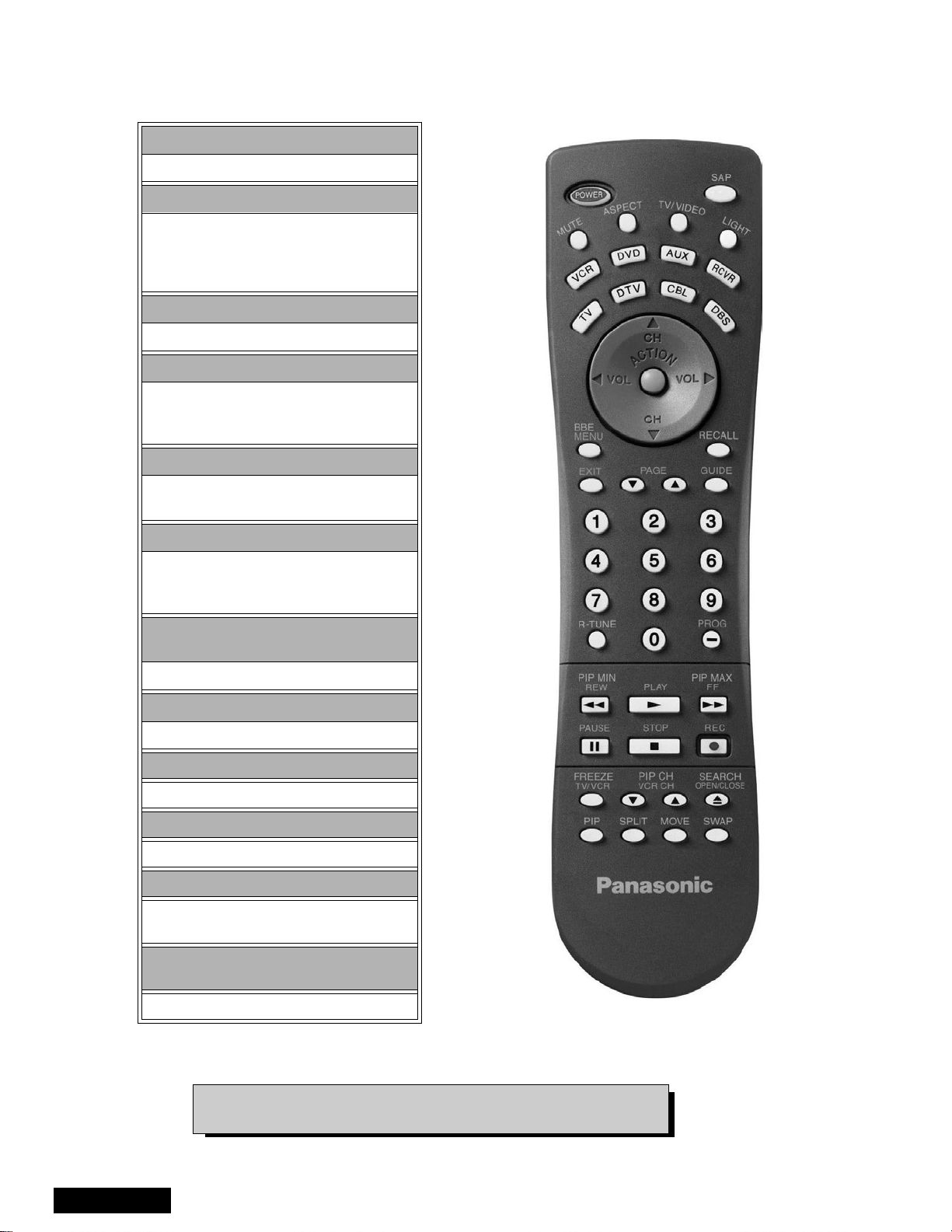
Remote - location of controls
POWER Button
Press to turn ON and OFF.
MUTE Button
Press to mute sound.
A second press resumes sound.
Press also to access and delete
Closed Caption display.
TV, VCR, DVD, CBS/CBL
Component function buttons
VOL (volume) Buttons
Press to adjust TV sound level.
Use with Channel buttons to
navigate in menus.
R-TUNE (Rapid Tune) Button.
Press to switch to theprevious
channel.
ACTION Button
Press to displaymain menu andaccess or
exit on screen features
and adjustment menus.
REW, PLAY, FF, TV/VCR, STOP, PAUSE,
REC & VCR CHANNEL Buttons
Component function buttons.
DBS EXIT& DBS GUIDE Buttons
DBS function buttons.
LIGHT Button
Press to light remote control buttons.
SAP
Access second audio program
ASPECT
Select picture size (ratio) to match
programming format
MOVE, PIP, SPLIT/SIZE, FREEZE, SWAP,
SEARCH, PIP CHANNEL
PIP function buttons
ServiceManual
Figure 6. Location of controls (EUR7603Z30 remote)
For additional information for this remote please refer to the
owner’s manual section remote operation, listed on the parts list.
-12-
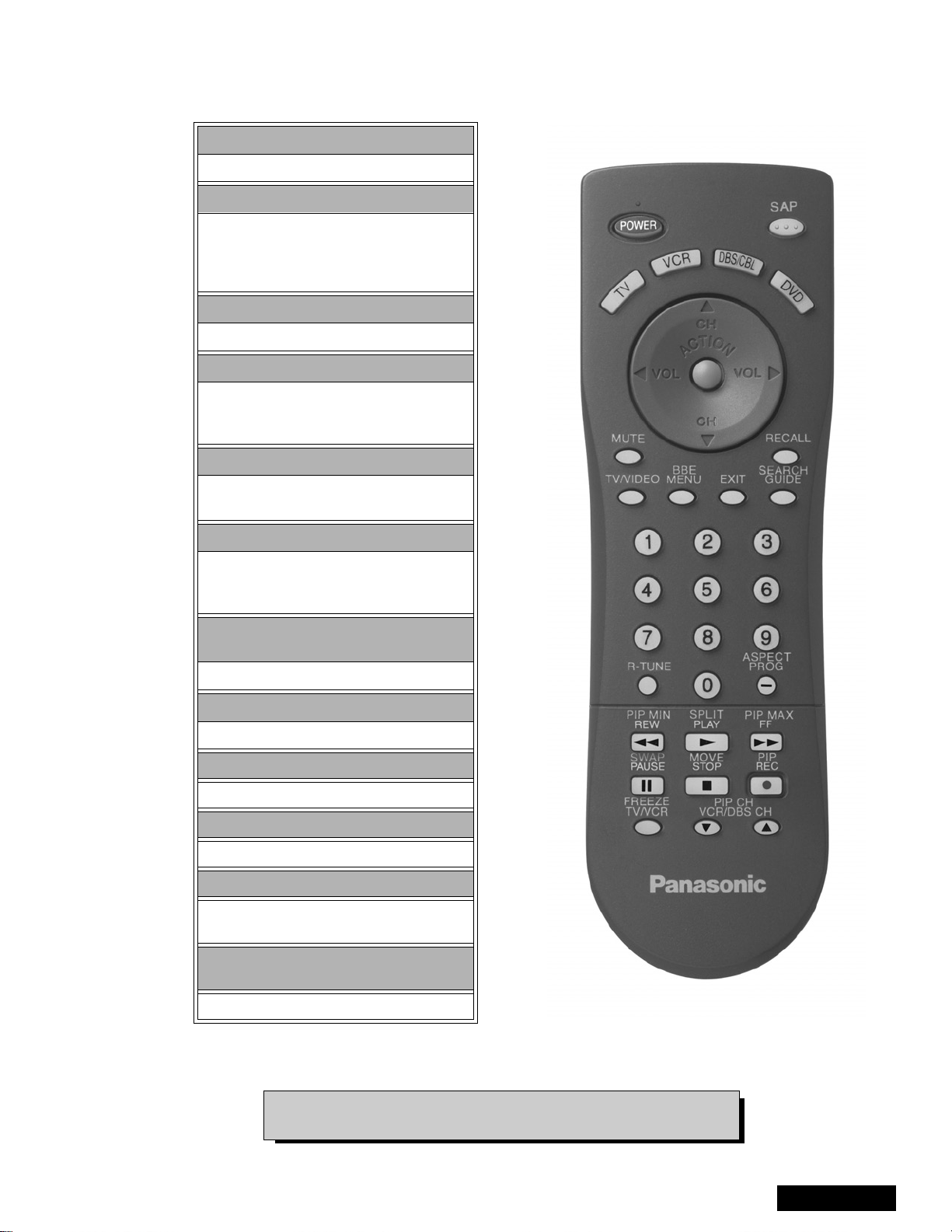
Remote-locationofcontrols
POWER button
Press to turn ON and OFF.
MUTE button
Press to mute sound.
A second press resumes sound.
Press also to access and delete
Closed Caption display.
TV, VCR, DVD, CBS/CBL
Component function buttons
VOL (volume) buttons
Press to adjust TV sound level.
Use with channel buttons to
navigate in menus.
R-TUNE (rapid tune) button.
Press to switch to theprevious
channel.
ACTION button
Press to displayMain Menu andaccess or
exit On Screen features
and Adjustment Menus.
REW, PLAY, FF, TV/VCR, STOP, PAUSE,
REC & VCR CHANNEL buttons
Component function buttons.
DBS EXIT& DBS GUIDE buttons
DBS function buttons.
LIGHT button
Press to light remote control buttons.
SAP
Access second audio program
ASPECT
Select picture size (ratio) to match
programming format
MOVE, PIP, SPLIT/SIZE, FREEZE, SWAP,
SEARCH, PIP CHANNEL
PIP function buttons
Figure 7. Location of controls (EUR7613Z40 remote)
For additional information for this remote please refer to the
owner’s manual section remote operation, listed on the parts list.
-13-
ServiceManual
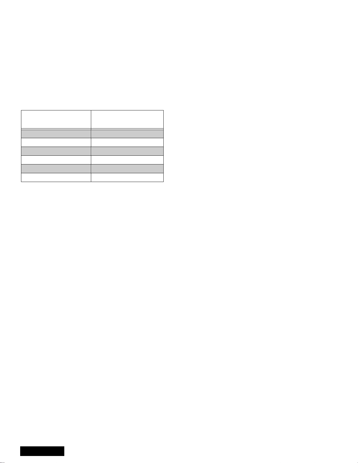
Auto diagnosis feature
This receiver incorporates a new auto-diagnosis
feature. With this new feature will be easier for the
technicial to detect the failures. There is a LED located
by the keyboard on the front panel, this LED will start
flashing when a failure is detected by the circuits
located in specific areas, depending on how many
times the LED is flashing, this will tell you what circuit
should be checked.
Make a count of flashing and see Table 3.
Please use this feature effectively especially for
intermittent problems.
NUMBER OF
FLASHES
1 +140
2LOWDC
3 CONVEREGENCE
4 HHS
5 IC4011
6IC4018
Table 3: SOS of front LED
After the count:
Proceed to check that area, verify what board is the
problem located, this way the area to check will be
reduced until the failure is found.
POSSIBLE CIRCUIT
ServiceManual
-14-
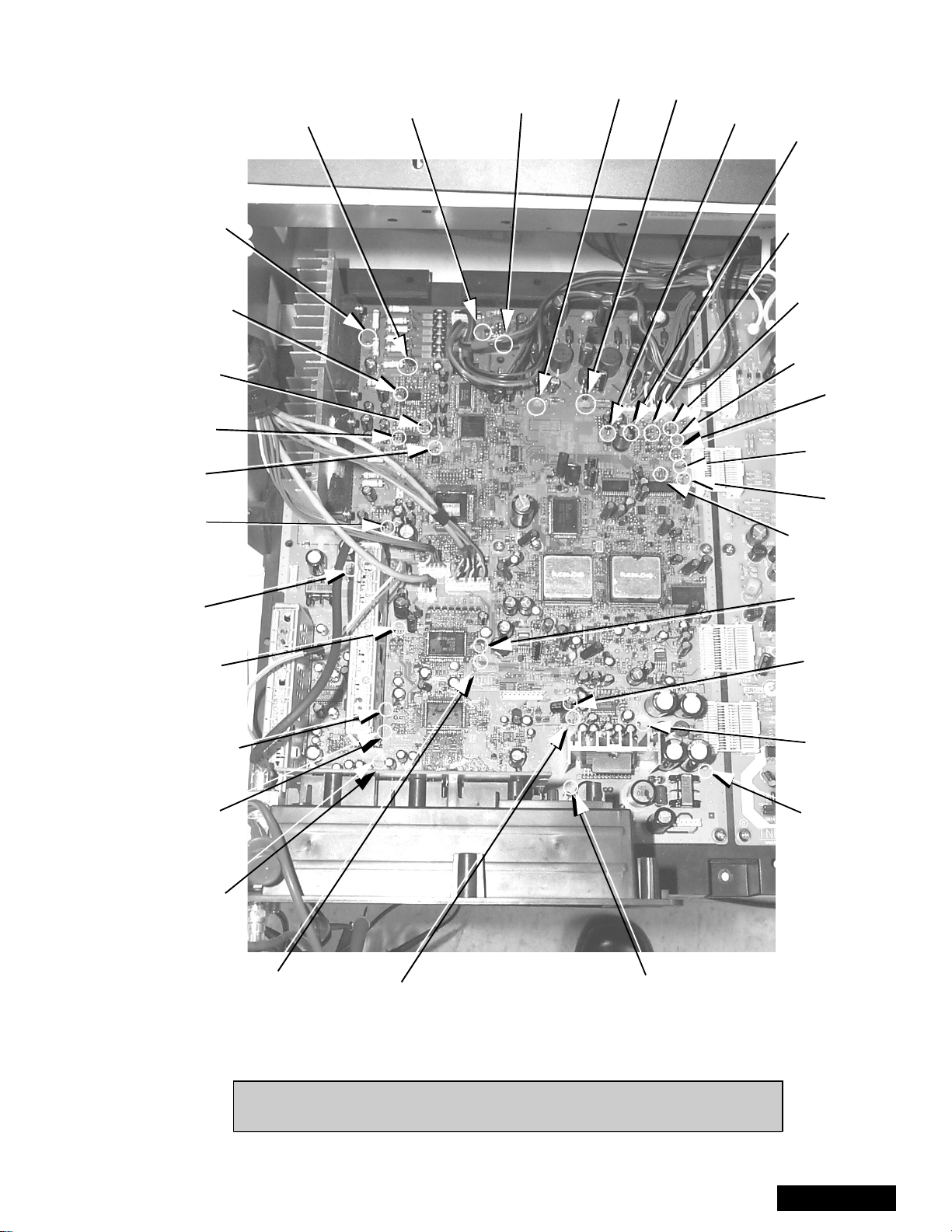
A-Board check points
-0.26V
-0.14V
0.00V
GV
-0.47V
RV
-0.53V
STB 3.3V
3.27V
BH
GH
RH
BV
-0.46V
CONV -18
-0.26V
CONV +18
-0.46V
9V
8.96V
2.5V
2.58V
VM
9.47V
G
3.6V
R
3.58V
B
3.45V
B
3.11V
R
3.17V
G
3.19V
Vp
0.00V
Hp
0.24V
STB 7V
6.96V
NTSC VIDEO
3.52V
SUB TUNER
VIDEO OUTPUT
2.13V
MAIN TUNER
VIDEO OUTPUT
2.25V
DTV1-Y
5.24V
MAIN-Y
3.77V
S-L
4.46V
SUB-Y
3.83V
S-R
4.46V
S+18
20.97V
S-18
-23.77V
S-R
0.00V
Figure 8. A-Board check points
Note: All the measurments are in DC with a digital multimeter, color bar
pattern, picture settings normalized and sound set to minimum.
-15-
ServiceManual
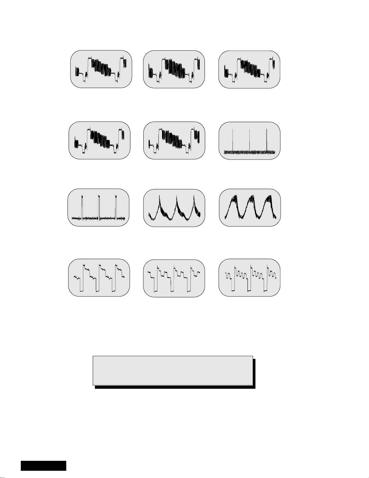
A-Board check points waveforms
Main tuner video output
15.72 kHz, 1 Vpp,
10µssec/div
Sub Y
15.72kHz, 1.92Vpp,
10µssec/div
HP
31.65kHz, 3.32Vpp,
10µssec/div
Sub tuner video output
15.72kHz, 1.00Vpp,
10µssec/div
NTSC video
15.72kHz, 2.02Vpp,
10µssec/div
Conv -18
60.24Hz, 0.75Vpp,
5µssec/div
Main Y
15.72kHz, 1.00Vpp
10µssec/div
VP
60Hz, 3.36Vpp,
5µssec/div
Conv +18
60.24Hz, 0.24Vpp,
5µssec/div
ServiceManual
G
31.65kHz, 4.72Vpp,
10µssec/div
Figure 9. A-Board check points waveforms.
Note: Waveforms were obtained with colorbar pattern,
picture settings normalized and sound set to
minimum.
R
31.65kHz, 4.44Vpp,
10µssec/div
-16-
B
31.65kHz, 4.40Vpp,
10µssec/div

Chassis & boards layout
A
D
LR
Top view
LG
R
LB
Back view
Figure 10. Chassis & boards layout.
Board description
A Main chassis, video processing, convergence,
audio processing
D Power supply, vertical out, horizontal out
LB Blue CRT output
LG Green CRT output
LR Red CRT output
RIRsensor
-17-
ServiceManual
Disassembly for service
Note:
Speaker grille removal (figure 11)
The speaker grille is secured to the cabinet of the PTV.
grip panel from the sides and middle upper part, gently
pull forward to remove. When reassembling, make
certain to firmly press on the panel where the insertion
points (5) are located, one at each corner and one at
the middle top edge.
Board ground wires may have to be disconnected to disassemble some boards. All ground wires must be
reconnected using jumper leads, if necessary, before power is applied to PTV for service.
Figure 11. Speaker grille removal.
Keyboard removal
1. Remove the speaker grille. See figure 11.
2. Unplug the connectors from the Keyboard and
front A/V inputs assemblies. Remove the screws
affixing the keyboard to the frame assembly. Tilt
the keyboard assembly upward and release it from
the screen frame assembly.
Speakers replacement
1. Remove the speaker grille. See figure 11.
2. Each speaker is secured to the cabinet with (4)
screws.
3. Disconnect the R & L speaker lead connectors
from the speaker units.
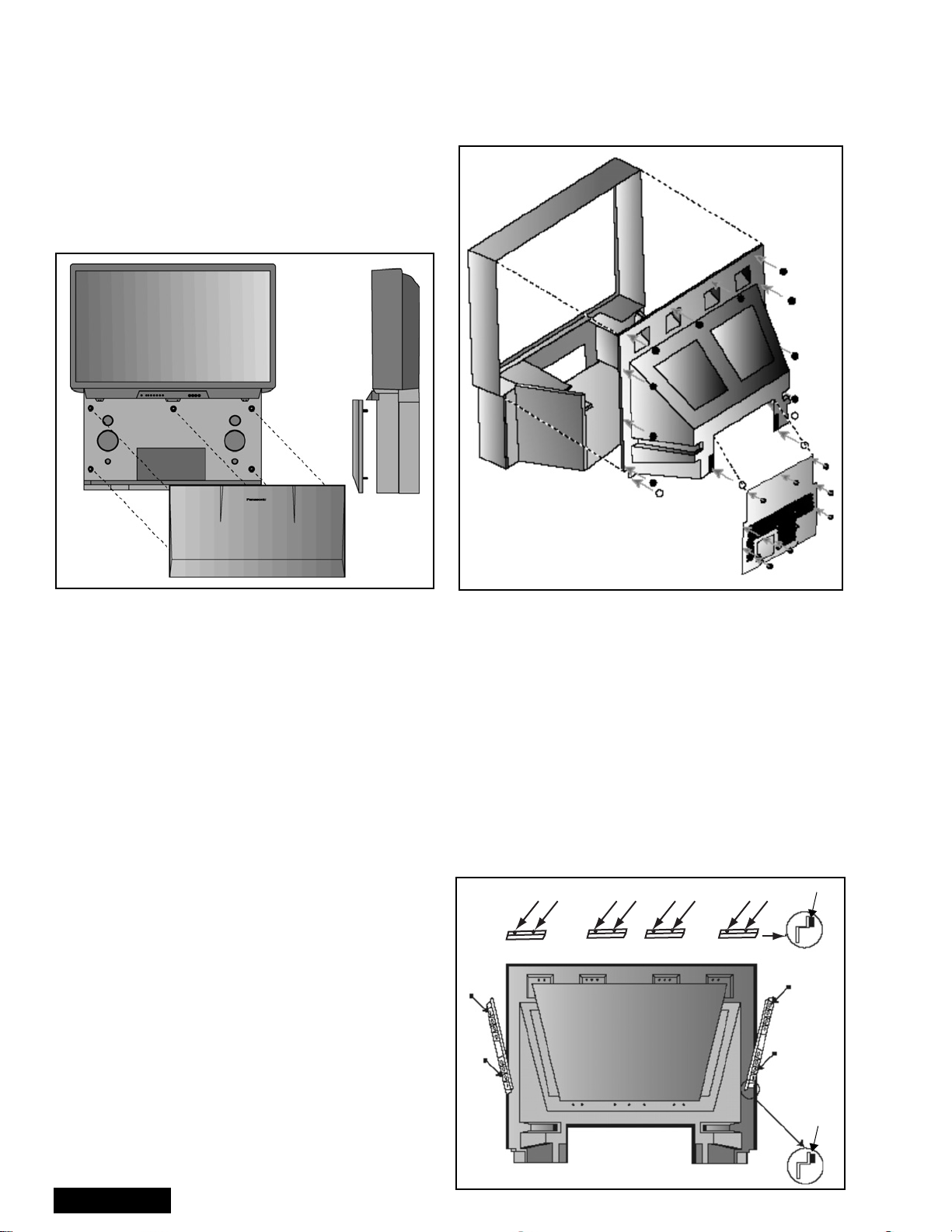
Cabinet back lower cover removal (figure 12)
1. Remove (7) hex screws around the perimeter,
marked with arrows. See figure 12 for screws
location.
2. Remove (3) screws from around the A/V terminal
board (marked with arrows).
Screw count:
14 fasten the top back cover;
10 fasten the lower back cover
Figure 12. Lower cabinet back removal
Cabinet back cover removal (figure 12)
1. Remove the cabinet back lower cover. (Detailed
previously).
2. The top back cover (plastic shell) is secured with
(14) screws around its perimeter. See figure 12 for
screws location.
3. Be careful not to damage the mirror secured to the
underside of the back cover.
Mirror removal (figure 13)
The mirror is attached inside the cabinet cover.
Carefully remove the cabinet cover to access its
interior surface and remove the screws securing the
brackets that hold the mirror at the top and sides to the
mirror. See figure 13.
Screws (12 places)
Brackets (4 places)
Felt
ServiceManual
-18-
Bracket
(2 places)
Mirror
Felt
cabinet cover
(Inside view)
Figure 13. Mirror removal
Disassembly for service (continued)
Screen frame removal
1. Remove the speaker grille. Disconnect the cables
leading to the keyboard and the AV panels and
remove the keyboard and AV panel assembly. The
assembly is secured by three (3) screws.
2. At this point the front cover is held only by four
screws, be careful not to push the cabinet forward.
3. Remove screws and tilt the assembly forwardwhile
lifting it out of place.
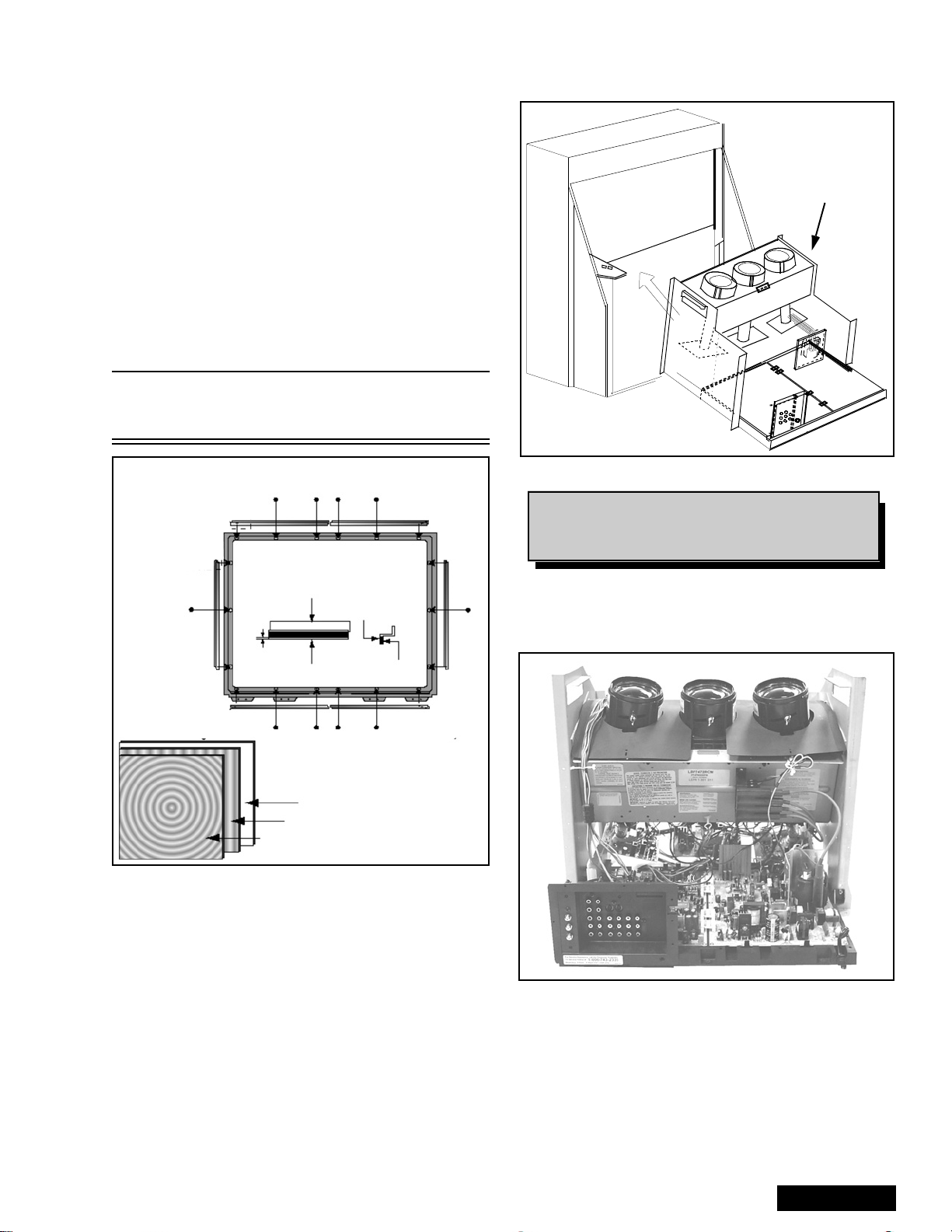
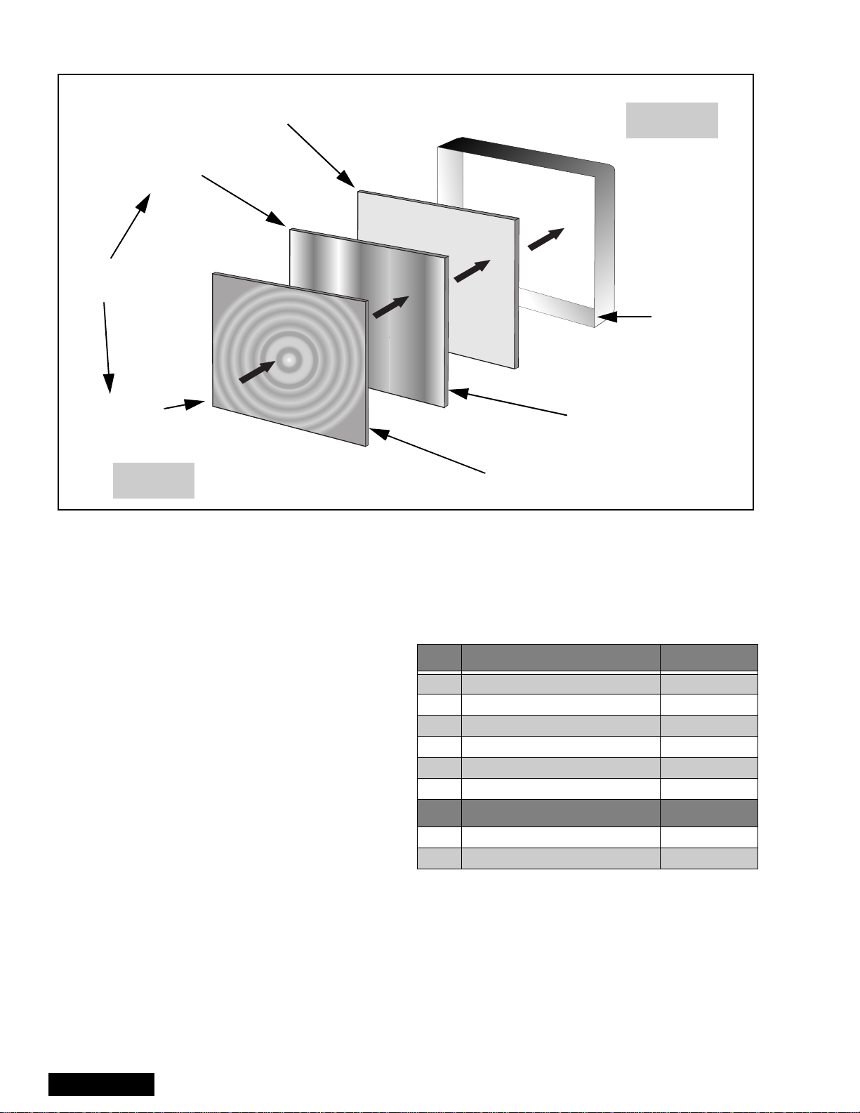
Screen assembly (figure 14)
1. Remove the screen frame. See screen frame
removal procedure above.
2. Place screen frame face down on a soft surface.
3. Remove all screen brackets and corner brackets
Note: The brackets are painted black (permanent
marker) on the edge to prevent reflection on
image.
Main Chassis Block
Figure 15. Chassis removal
Note: Main chassis block can be serviced either
in normal position or layi ng on its b ack
(protect hookup terminal from damage).
Bracket
0 ± 0.5mm
Felt
Screws (18 places)
Lenticular screen
Fresnel screen
Fresnel
screen
Double
adhesive tape
Protective screen
Figure 14. Screen assembly
4. Note exact orientation and order of each screen.
The orientation and order of the screens is critical
for displaying pictures properly. Detailed screen
assembly can be seen in figure 14.
Main chassis block (figure 15)
1. Remove the speaker grille. See figure 11.
2. Remove the cabinet back lower cover. See
figure 12.
3. The main chassis block is secured to the cabinet
by screws at front, behind the Speaker Grill and
inside on the bottom of the optical frame).
4. Remove the horizontal barrier panel at the back of
the cabinet.
5. Unplug connectors (K1, G1 and speaker
connectors) and pull out the main chassis block.
Chassis assembly
The chassis assembly shown in figure 18 includes all
the electrical and optical (light box) components.
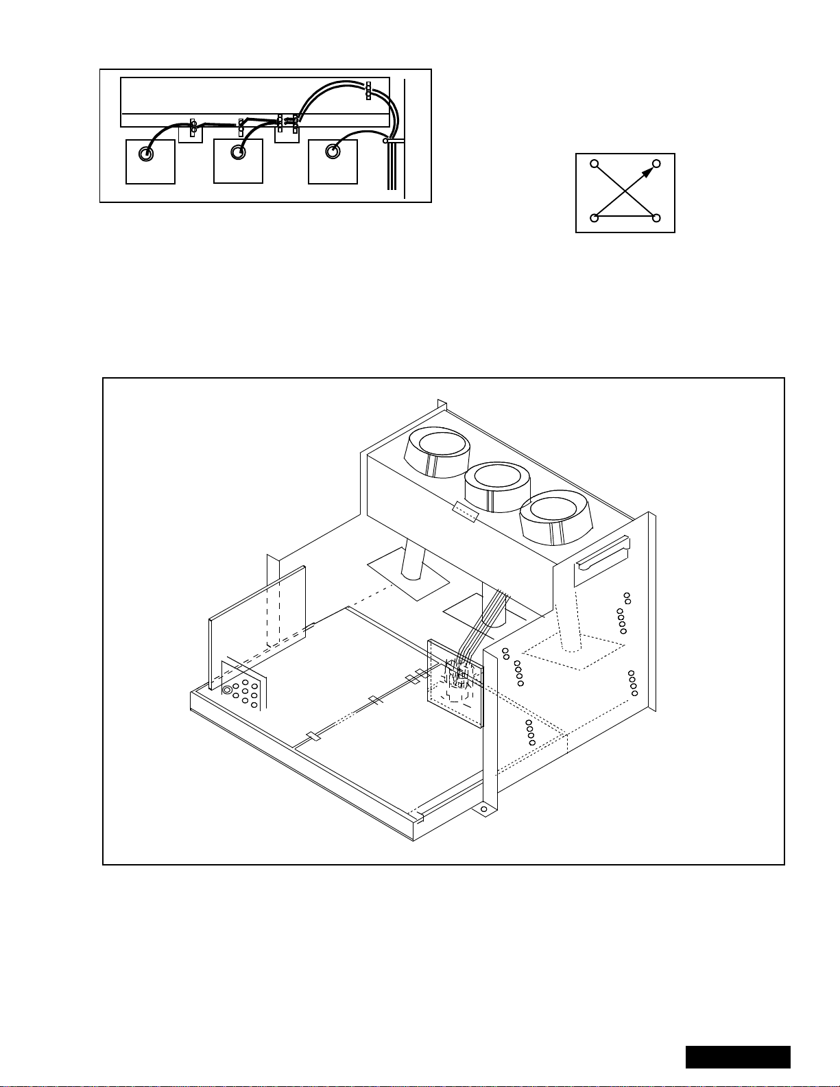
Figure 16. Chassis rear view
-19-
ServiceManual
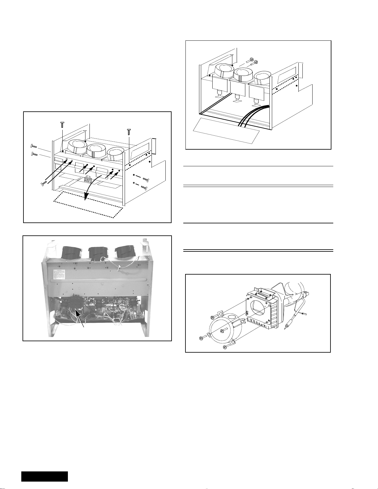
Disassembly for service (continued)
Disassembly for CRT replacement
To facilitate CRT replacement, the complete CRT
mounting chassis does not need to be removed.
1. Remove the main chassis block from the cabinet.
See figure 15.
2. Remove the optical bracket metal cover (rear side)
by removing (6) screws from back, (2) screws from
top, and (2) screws from each side. See figure 17
& figure 18.
REAR VIEW
Screws
(6) places
Optical bracket
Pull down
Figure 17. CRT replacement
Optical bracket cover
Figure 19. CRT replacement.
** CAUTION: Support the CRT assembly
when loosening screws.
8. Release CRT anode lead from CRT chassis wire
clamp and all other wires from holders.
9. Loosen a screw that secures the DY and remove it
from the CRT neck.
Caution: To insure x-ray radiation protection, the lens
must be mounted in place at all times when
power is applied to the PTV.
CRT replacement
1. Remove CRT focus lens assembly (4 screws).
Lens
(4) Screws
Focus pack
Figure 18. Light box front view
3. Remove the defective CRT anode lead from the
high voltage distributor block that is mounted on
the flyback transformer. Discharge to CRT chassis.
4. Unplug connectors from the B-Board. See board
layout. B9 for red, B10 for green, or B11 for blue.
5. Unplug the defective CRT black DAG ground
connector from the CRT Board.
6. Remove the CRT Board from the defective CRT
neck.
7. Remove (2) screws from the defective CRT
housing. See figure 19.**
CAUTION: Do not remove the (4) CRT
lens screws.
ServiceManual
Figure 20. CRT assembly.
2. Lay CRT face down on a soft cloth.
3. Note position of yoke with centering tabs and
remove from defective CRT.
4. Remove CRT DAG ground from defective CRT.
Mount it on the replacement CRT exactly as it was
on the defective CRT.
Note: Replacement CRT is supplied with H.V. anode
lead attached.
5. Wire the anode lead wire.
-20-
6. Wire the anode lead wire.
Optical bracket (front)
8. Press yoke against bell of CRT and tighten the
clamp just snug enough so it will not easily shift.
9. Assemble CRT focus lens assembly to new CRT
with (4) screws. Make sure focus lens adjustment
nut is in the same location as on other CRT focus
lens.
RED CRT GREEN CRT BLUE CRT
Figure 21. Wire guide.
7. Install yoke with other CRT neck assemblies on
CRT neck in the same order and position as
removed from the defective CRT.
Optical block position adjustment
1
4
23
Figure 22. CRT screw tightening order .
Note: Please assemble with screws in the order
shown and tighten with the same torque.
Figure 23. Optical block position.
The optical block mounting has holes to allow for the
different size projection screens. These mounts will
adjust to projection screens.
51/61
46
51/61
46
51/61
46
51/61
46
51/61
46
51/61
46
If the optical block is removed for service or is
replaced, it is important that the correct mounting holes
are used.
-21-
ServiceManual
PTV screen assemblies
Label on
lower left corner
(front side)
Labels on
opposite sides
Label on
lower left corner
(rear side)
REAR
Protective screen
FRONT
Front cabinet
Lenticular screen
(note vertical ridges)
Fresnel screen
(note circular ridges)
Figure 24. Screen assemblies.
B+ voltages table
Preparation:
Set the following controls
Picture..........................Normal.
Bright ...........................Normal.
Volume......................... Min. (0).
Procedure:
1. Apply a white NTSC pattern.
2. Connect the (-) lead of the digital voltmeter to
TPGND1 (cold ground).
3. Connect the (+) lead of the digital voltmeter to each
test point and confirm the B+ voltages (see
Table 4).
No. Test point (D-Board) Voltage
1 TPD14 138.6±1.0
2 TPD13 19.0
3 TPD12 19.0±1.5
4TPD11 -19.0
5 TPD10 22.0±1.5
6 C845 (-) -22.5
No. Test point (A-Board) Voltage
1TPA031 9.0±0.5
2 TPA030 5.0±0.5
Table 4: B+ voltages table
±1.5
±1.5
±1.5
ServiceManual
-22-
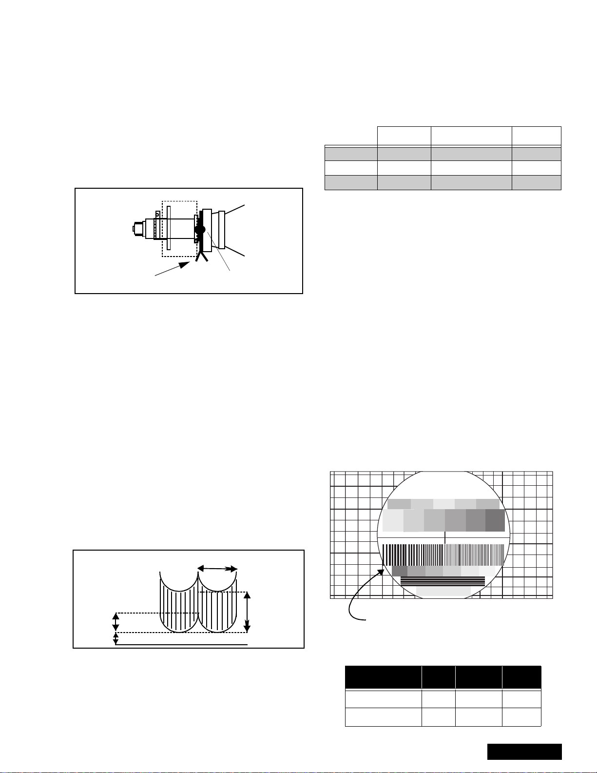
CRT set up
CAUTION: Insure yoke plugs on the A-Board
are reconnected before turning the PTV
ON to prevent damage to the horizontal
output transistor and/or CRTs.
1. Connect test generator to the antenna terminal and
set for a monoscope pattern.
2. Loosen yoke clamp, seat yoke against bell of CRT
and rotate to correct yoke tilt (compare to adjacent
CRT). Tighten yoke clamp.
3. Remove adhesive from centering tabs and set
centering t abs for zero correction. (figure 25)
Centering magnets
Figure 25. Adhesive removal
4. Cover replacement CRT lens and static converge
the tubes not replaced, if needed. Check size and
linearity of pattern and adjust as required.
5. Uncover replacement CRT lens and cover other
two CRT lenses. Adjust electrical and optical focus
(lens), if required.
6. Uncover all CRT lenses and use yoke centering
magnet to converge replacement CRT (in center
area of screen only) with other two CRTs.
Disregard non-convergence in areas other than
center area.
7. Perform white balance adjustments.
Dynamic focus adjustments
1. Focus adjustments should be performed after 1
hour of aging.
2. Use oscilloscope with 100 : 1 probe.
3. Apply a NTSC crosshatch pattern to adjust focus.
4. Adjust the red, blue and green focus VR on the
focus block for best focus of overall picture of each
CRT. (figure 28)
Adhesive
16.7ms (V Rate)
Procedure:
Note: 1080i, 480p, 480i pattern can be obtained from
Panasonic’s TU-DST51 set-top box DTV
decoder.
1. Enter to service mode and set the following default
DATA:
NTSC NTSC ZOOM 1125i
H-PARA +317 +263 +317
V-SAW -23 -35 -23
V-PARA +69 +117 +69
Note: The signal (NTSC, 1125i) (NTSC ZOOM
option), should be displayed to enter values for
specific format adjustment.
2. For 1125i (1080i) set the default values.
3. For NTSC and NTSC ZOOM apply a white pattern
and perform the following steps.
4. Connect the scope probe to TPD30, GND to
TPD31.
5. Confirm that level of A is 600_V ± 100_V, adjust
H-PAR DAC to set to specification level.
6. Confirm that level of B is 280_V ± 50_V, adjust
V-PAR DAC to set to specification level.
7. Confirm that level of C is more tha 20 V, adjust
H-PAR DAC to set to specification level.
Focus - Electrical & optical adjustments
(use for minor adjustment or for final adjustment,
for complete adjustment see following section.)
Electrical adjustment
Note: 1080i, 480p, 480i pattern can be obtained from
Panasonic’s TU-DST51 set-top box DTV
decoder.
1. Apply a NTSC crosshatch with dots pattern.
Panasonic
FORMAT
A
B
280_V ± 100_V
B
>20_V
C
A
600_V ± 100_V
GND
Figure 26. D. Focus adjustment waveform
5. To change DAF DA TA, enter to service mode, then
press POWER on remote to display DACs menu,
then select DAC by pressing CH (RIGHT/LEFT)
and VOL (UP/DOWN), then press ACTION to enter
to DAC, then adjust by pressing VOL (RIGHT/
LEFT); press ACTION, to save press ACTION
again or OTHER to exit without saving.
-23-
Adjust electric focus VR
and lens focus on this circle
Figure 27. Lens focus adjustment
Table 5: Focus points
RED GREEN BLUE
Electric focus B A/B A
Optical Focus B A/B A
ServiceManual
2. Set VIDEO C_OFF DAC from 00 to 02, and project
only red. Adjust red focus VR so that focus is best..
screen
+
+
+
GB
R
+
R
++
GB
focus
Figure 28. Focus pack
3. Adjust red lens focus (mechanical) until focus is
best.
4. Adjust red focus VR again.
5. Set VIDEO C_OFF DAC from 00 to 01, and project
only green.
6. Repeat steps for green only.
7. Set VIDEO C_OFF DAC from 00 to 03, and project
only blue.
8. Repeat steps for blue only.
Focus - Optical lens adjustment
Optical adjustments
Note: This adjustment normally should not require
resetting unless the lens has been replaced or
adjustment has changed.
Electric & VM focus adjustment, complete
adjustment
(Perform this adjustment when a CRT is replaced
or when major adjustment is required)
Preparation:
1. Apply a NTSC crosshatch pattern with dots.
2. Set CONV “MUTE” DAC from 0 to 1 (disabling
digital convergence.)
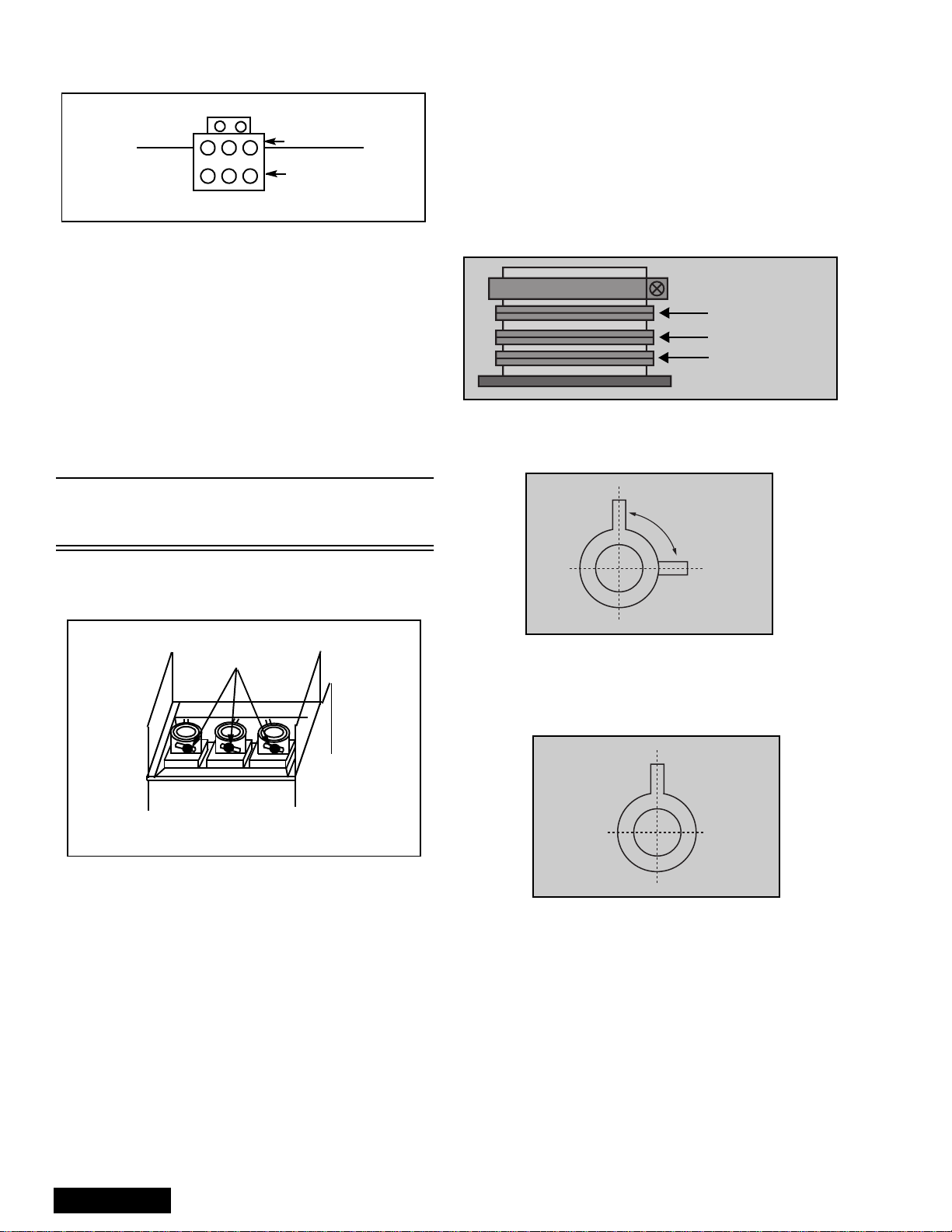
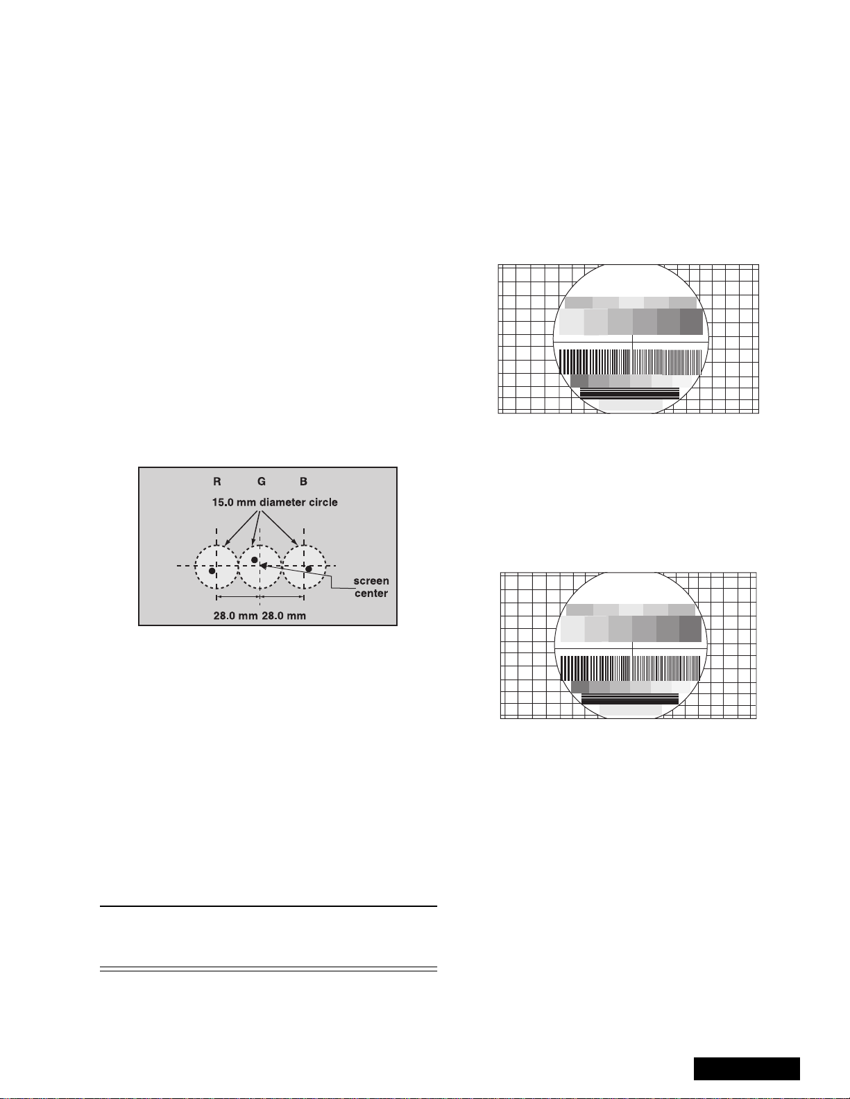
3. Position the longer tab of the four-pole magnet to
90 degrees (uncorrected position). (see figure 31).
6-pole magnet
(Dummy ring)
4-pole magnet
Alignment magnet
Figure 30. VM coil with focus
correction magnet
Set 90 deg rees
1. Optical focus adjustment is located on the top of
each CRT lens system. Loosen the adjustment
knurled locking knob. (figure 29)
Adjustment knurled
locking knobs
BGR
REAR VIEW
Figure 29. Optical lens focus adjustment
2. Turn the PTV ON. Apply and view a crosshatch
with dots pattern.
3. Adjust each lens focus for best focus while viewing
each CRT .
4. Cover the red and blue CRT, projecting green only.
Rotate the green lens for best focus around screen
center area.
5. Do the same for the red focus lens while projecting
red only.
6. Repeat for blue.
Figure 31. 4-pole magnet
4. Position the long tab of all alignment magnets and
of the dummy ring together in an uncorrected
position. (See figure 32).
Figure 32. Alignment magnet
(or dummy ring)
Procedure:
1. Apply an NTSC cross hatch pattern with dots.
2. Assure that digital convergence is disabled (DAC
MUTE from 0 to 1).
3. Set VIDEO “C_OFF” DAC from 00 to 02, to project
red only.
4. Turn the red electrical focus adjustment VR (on
focus pack) fully counterclockwise and note the
position of the dots at the center of the picture.
5. Turn the red electrical focus adjustment VR
fully clockwise.
ServiceManual
-24-
6. If the position of the dotsat the center of the screen
moves from the position noted in step 4., adjust the
alignment magnets until the dots are in the same
position as noted in step 4.
7. Turn the red electrical focus adjustment VR (on
focus pack) fully counterclockwise and confirm that
the position of the dots at the center of the screen
did not move from their position noted in step 4.
8. If the position of the dots at the center of screen
moved, repeat from step 4.
9. If the position of the dots moved after repeated
adjustments, adjust until the movement of the dots
is minimized.
10. Turn the red focus VR fully clockwise.
11. Adjust t he 4-pole magnets until the shape of the
dots at the center of the screen is circular .
12. Adjust red focus VR until optimum focus is
achieved.
13. Apply NTSC crosshatch with dots or any other
available pattern applicable to the following.
14. Confirm that the picture is correctly aligned in the
center of the screen, shown in figure 33, adjust the
centering magnets. Repeat the alignment magnet
adjustments and four pole magnet adjustments
(step 1. ~ step 12.).
NTSC Vertical size adjustment (VSIZE)
Note: 1080i, 480p, 480i pattern can be obtained from
Panasonic’s TU-DST51 set-top box DTV
decoder.
1. Apply a NTSC pattern (see avobe note) .
2. Set VIDEO “C_OFF” DAC from 00 to 01
(to project only green).
3. Adjust centering magnets so that the center of the
pattern get aligned with screen frame center.
4. Adjust VDEF “VSIZE” DAC until vertical size is
proportional on top and bottom. (See figure 34)
5. Set VIDEO “C_OFF” DAC from 01 to 00
Panasonic
FORMAT
Figure 34. Vertical size adjustment
HD 1080i Vertical size adjustment (VSIZE)
Note: 1080i, 480p, 480i pattern can be obtained from
Panasonic’s TU-DST51 set-top box DTV
decoder.
1. Apply a HD 1080i pattern (see avobe note).
2. Repeat vertical size adjustment from step 2
Figure 33. Centering magnet
15. Apply an NTSC cross hatch pattern with dots.
16. Set VIDEO “C_OFF” DAC from 00 to 01, to project
green only .
17. Repeat above procedures for the green.
18. Set VIDEO “C_OFF” DAC from 00 to 02, to project
red only.
19. Repeat above procedures for the blue.
20. Enable digital convergence by changing DAC
MUTE from 01 to 00.
21. Following adjustments, paint position of DY
centering magnets and fix the centering magnets of
DY, dummy rings of VM coil, four pole magnets of
VM coil and the alignment magnets of VM coil to
prevent them from moving.
Note: Please See “Service mode (electronic
controls)” on page 34 for entering and exiting
service mode.
Panasonic
FORMAT
Figure 35. Vertical size adjustment
-25-
ServiceManual
NTSC ZOOM Vertical size adjustment
(VSIZE)
Note: 1080i, 480p, 480i pattern can be obtained from
Panasonic’s TU-DST51 set-top box DTV
decoder.
1. Apply a NTSC pattern (see avobe note) .
2. Change aspect to ZOOM mode.
3. Repeat vertical size adjustment from step 2
4. Try making circle seem rounded (in proportion)
Panasonic
FORMAT
HD 1080i Horizontal phase adjustment
(H-POS)
Note: 1080i, 480p, 480i pattern can be obtained from
Panasonic’s TU-DST51 set-top box DTV
decoder.
1. Apply a HD 1080i pattern.
2. Repeat NTSC horizontal phase adjustment from
step 2.
Panasonic
FORMAT
Figure 38. H Phase adjustment
Figure 36. Vertical size adjustment
NTSC Horizontal phase adjustment
(H-POS)
Note: 1080i, 480p, 480i pattern can be obtained from
Panasonic’s TU-DST51 set-top box DTV
decoder.
1. Apply a NTSC crosshatch pattern with dots.
2. Set CONV “MUTE” DAC from 00 to 01 (disabling
digital convergence).
3. Set VIDEO “C_OFF” DAC from 00 to 01 to project
only green.
4. Turn green deflection yoke until line is perfectly
horizontal.
5. Adjust H-POS DAC data so that pattern is in the
center of screen.
Figure 37. H phase adjustment
Trapezoid adjustment (EWTRA)
1. Set default value
NTSC Pincushion adjustment (PCC)
Note: 1080i, 480p, 480i pattern can be obtained from
Panasonic’s TU-DST51 set-top box DTV
decoder.
Procedure:
1. Apply a NTSC crosshatch pattern with dots.
2. Set VIDEO “C_OFF” DAC from 00 to 01 to project
only green.
3. Set DAC MUTE from 00 to 01 (disabling digital
convergence).
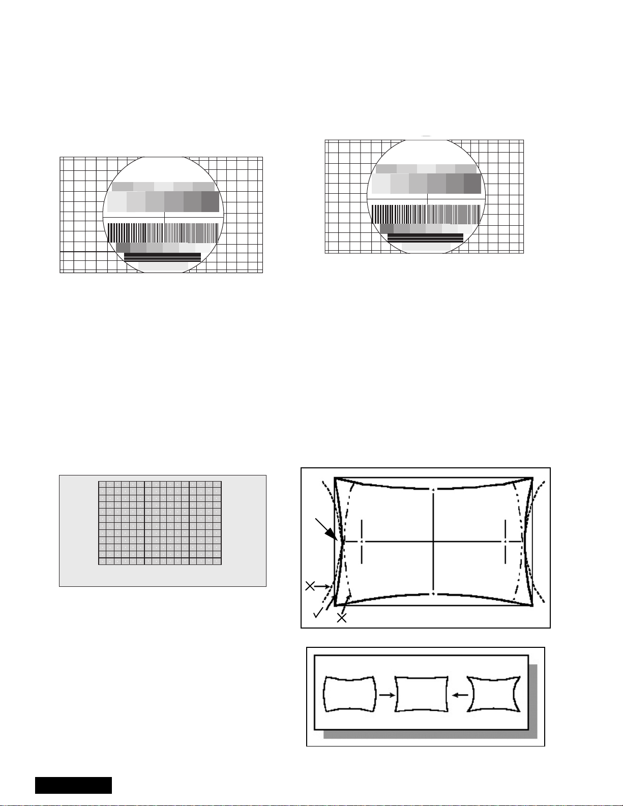
4. If the distance at “A” is not 10 ± 5mm, enter “H
DEF” “H WID” mode and adjust by VOLUME UP/
DOWN until it is 10 ± 5mm. See figure 39.
A
A=10±5mm
Line with dot
6. Enable digital convergence by changing DAC
MUTE from 01 to 00.
7. Set VIDEO “C_OFF” DAC from 01 to 00.
ServiceManual
Figure 39. Pincushion adjustment
NOT GOOD GOOD NOT GOOD
5. If not all corners of cross hatch appear in screen,
enter V DEF “V SIZE” mode and adjust until they
-26-
appear.
6. Confirm that measurement of “A” has not changed.
7. Enable digital convergence by changing DAC
MUTE from 01 to 00.
8. Set VIDEO “C_OFF” DAC from 01 to 00.
HD 1080i Pincushion adjustment (PCC)
Note: 1080i, 480p, 480i pattern can be obtained from
Panasonic’s TU-DST51 set-top box DTV
decoder.
Procedure:
1. Apply a HD 1080i pattern.
2. Repeat NTSC pincushion adjustment from step 2
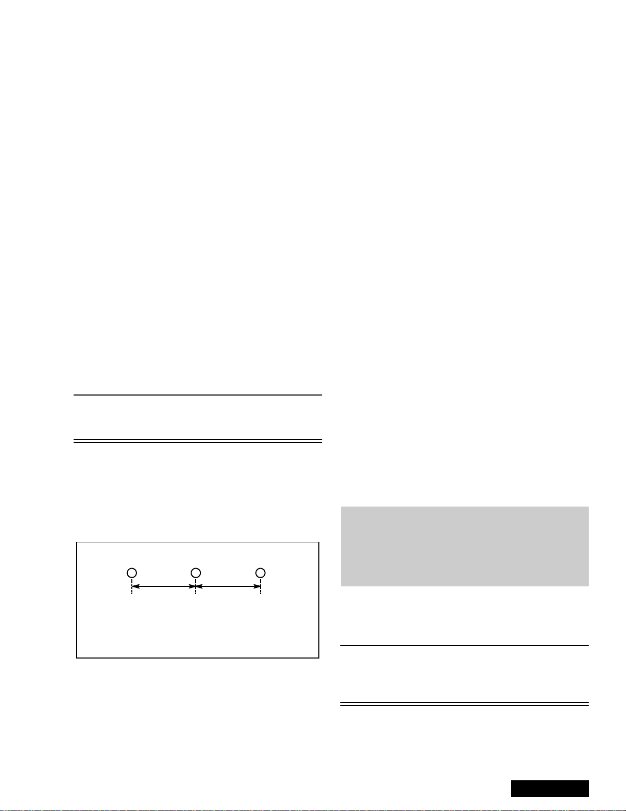
Centering magnets adjustment
Note: 1080i, 480p, 480i pattern can be obtained from
Panasonic’s TU-DST51 set-top box DTV
decoder.
Procedures:
1. Apply a NTSC crosshatch pattern with dots.
2. Set VIDEO “C_OFF” DAC from 00 to 01 to project
only green.
3. Set DAC MUTE from 00 to 01 (disabling digital
convergence).
4. Loosen the deflection coil screw on the green CRT.
5. Adjust green deflection coil until the horizontal
center line is horizontal.
6. Adjust centering magnets until the green pattern is
equal on left and right. Adjust also for horizontal
and vertical tilt.
Note: Push deflection coil to top of CRT neck,
then tighten deflection screw after adjusting
each CRT centering and tilt.
7. Set VIDEO “C_OFF” DAC from 01 to 03 to project
only blue. Adjust deflection coil until the horizontal
center line matches the pattern of the grid and is
leveled.
8. Adjust blue centering magnets until the pattern
center is at the appropriate distance as indicated
on figure 40.
RG
dd
B
12. Enable digital convergence by changing DAC
MUTE from 01 to 00.
13. Set VIDEO “C_OFF” DAC from 02 to 00. Following
the adjustment, make sure that all deflection coils
are pushed completely toward the CRT cones and
that all screws are tightened.
NTSC Horizontal size adjustment (H WID)
Note: 1080i, 480p, 480i pattern can be obtained from
Panasonic’s TU-DST51 set-top box DTV
decoder.
This adjustment is intended to adjust horizontal size of
the picture.
1. Apply a NTSC pattern.
2. Set VIDEO “C_OFF” DAC from 00 to 01 to project
only green.
3. Set DAC MUTE from 00 to 01 (disabling digital
convergence).
4. In service mode, adjust H-WID DAC until the
picture horizontal size is balanced at left and right
side of screen.
5. Set DAC MUTE from 01 to 00 (disabling digital
convergence).
6. Set VIDEO “C_OFF” DAC from 01 to 00.
HD 1080i Horizontal size adjustment
(H WID)
Note: 1080i, 480p, 480i pattern can be obtained from
Panasonic’s TU-DST51 set-top box DTV
decoder.
This adjustment is intended to adjust horizontal size of
the picture.
1. Apply a HD 1080i pattern.
2. Repeat NTSC horizontal size adjustment from
step 2.
Convergence adjustment
Note: 1080i, 480p, 480i pattern can be obtained from
Panasonic’s TU-DST51 set-top box DTV
decoder.
Note: It is strongly recommended to first read and
understand the following section prior to
make any adjustment.
Convergence adjustment must be perform
for 480i-p (same for interlace & progressive),
1080i and ZOOM 480i.
dmeasuredinmm
28 mm
Figure 40. Centering magnets adjustment.
9. Set VIDEO “C_OFF” DAC from 01 to 02 to project
only red.
10. Adjust red deflection coil until the horizontal center
line matches the pattern of the grid and is leveled.
11. Adjust red centering magnets until the pattern
center is at the appropriate distance as indicated
on figure 40.
TurnPTVonandallowittowarmupfor30
minutes prior to making adjustments
(WHITE PATTERN).
Note:
Preparation:
Place the convergence alignment template (see
“Convergence alignment template” on page 33) over
the PTV screen. Align the center lines of the template
with the mechanical center markerson the PTV screen
-27-
This PTV uses the scheme described below to
correct for misconvergence of the three CRT
projection tubes. There are various modes to
this operation.
ServiceManual
frame. If the template is not available, create one using
the dimensions provided in “Convergence alignment
template” on page 33.
Remote control must be used during the procedure.
Note: Apply the convergence alignment template to
the PTV screen frame to converge the green
raster only. Remove the convergence
alignment template following this alignment.
The red and blue rasters can then be aligned
to the green raster.
Raster Setup:
1. Enter to service mode (red CHK).
2. In SET-UP (roller guide menu) CONVERGENCE 1
set all values to 0.
3. Cover red & blue lens with caps.
4. Apply a pattern to adjust specific format:
• NTSC signal to adjust 480i-p (same for
interlace and progressive)
• 1080i signal to adjust 1080i
• 480i signal with PTV in ZOOM aspect to
adjust Z480i
5. Select DAC COARSE, then press ACTION to enter
to “CONVERGENCE ADJ” mode.
6. Press “0” key on remote.
7. Press ACTION key on remote to enter to
“TEST_POS” mode.
8. Move pattern by pressing VOL right - left and CH
up - down so that the cursor center overlap
monoscope pattern center.
30
Figure 41. Aligning cross-hair
cursor with center of pattern
9. Press “5” key on remote to exit superimpose mode
(monoscope pattern disappear).
10. Press “TV/VIDEO” key to enter “DATA_POS” mode
11. Adjust by pressing VOL right - left so that peak of
curve is the same position as center of cursor.
13. Press “5” key on remote so that monoscope
pattern appears (superimpose mode)
14. Move cursor by pressing VOL right - left and CH
up - down so that cursor center overlap
monoscope pattern center
15. Press “0” key to go back to “CONVERGENCE
ADJ” mode.
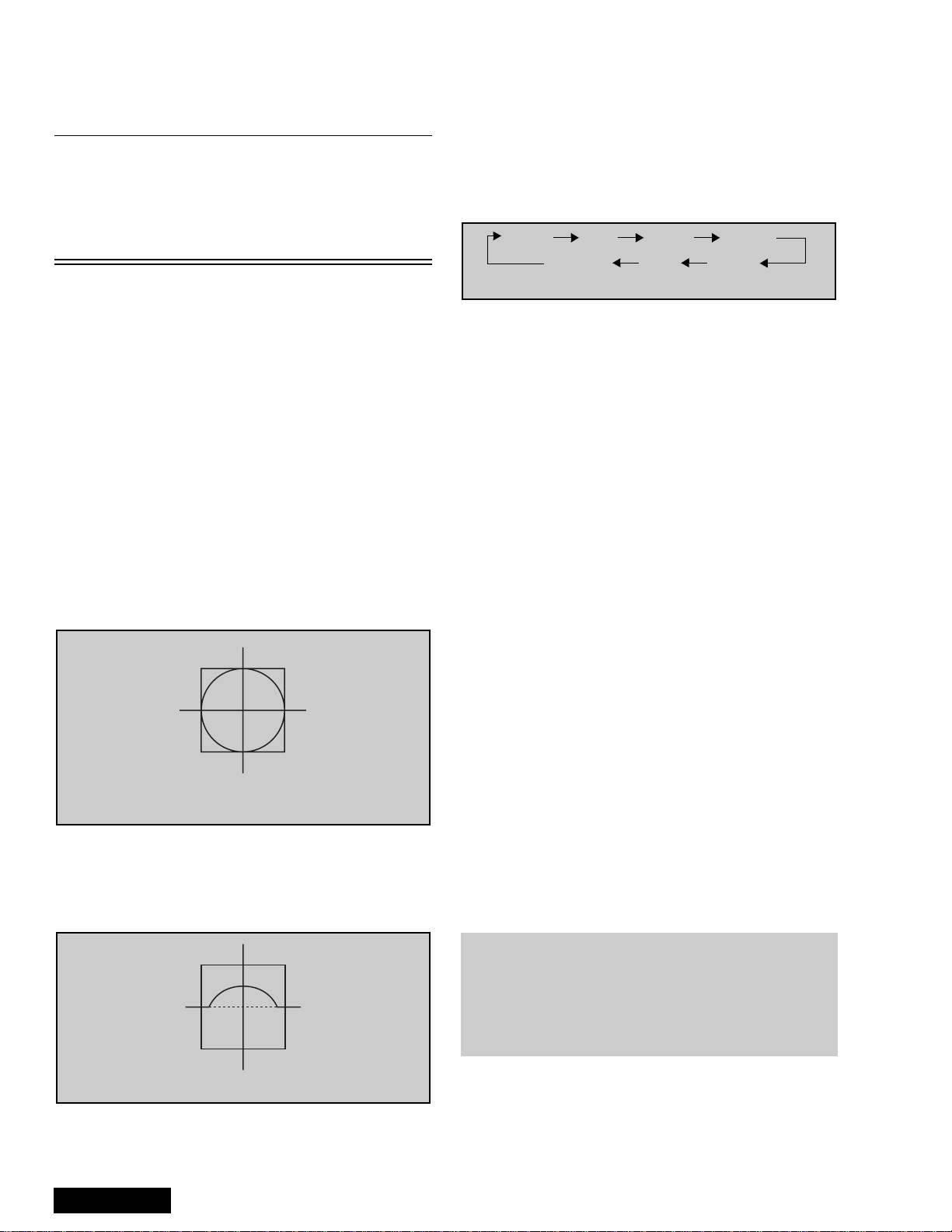
16. Press “TV/VIDEO” key to cycle through “COARSE
ADJ. MODE” options.
Static Size Skew Linear
KeyPinCorner
Figure 43. Coarse modes cycle
17.Tochangeto“FINEADJUSTMENTMODE”
options (DAC FINE), press “TV/VIDEO” key on
remote for at least 3 seconds, to go back to
“COARSE ADJ MODE” options press “TV/VIDEO”
on remote again for 3 seconds.
18. In “FINE ADJUSTMENT MODE” options, press
“MUTE” key on remote to switch between “cursor”
mode and “data” mode.
• Cursor mode: Allows cursor movement by
pressing VOL right - left and CH up - down.
• Data mode: Allows making adjustment by
pressing VOL right - left and CH up - down.
19. Either “COARSE ADJUSTMENT MODE” options
or “FINE ADJUSTMENT MODE” options, press “RTUNE” repeatedly key on remote to cycle through
different color adjustments (R, G , B, White)
20. To store adjustments press “7”, then “ACTION” key
on remote, otherwise press “POWER” then
“ACTION” to exit adjustments without saving.
21. Remote functions:
• 1,3.......... changecolorviewadj
• 2..................changepattern
• 7.......................savedata
• 5.........................overlap
• POWER....................toexit
• RECALL ............displayvalues
• R-TUNE...............cycle colors
• TV/VIDEO ............changemode
3secs.......changeoptions
Coarse adjustment mode (COARSE)
Note: 1080i, 480p, 480i pattern can be obtained from
Panasonic’s TU-DST51 set-top box DTV
decoder.
Figure 42. Symmetrical shape
12. Press “TV/VIDEO” key on remote to enter
“OSD_POS” mode.
ServiceManual
Note: It is strongly recommended to first read and
understand the following section prior to
make any adjustment.
Convergence adjustment must be perform
for 480i-p (same for interlace & progressive),
1080i and ZOOM 480i.
Procedure:
1. Enter to “G-SIZE” mode:
• DAC COARSE
• Press ACTION on remote
• TV/VIDEO (repeatedly)
• R-TUNE (repeatedly)
-28-
2. Press “2” repeatedly and apply the pattern of
border and cross.
3. Press RECALL to display values
4. Adjust size so that the line of the border closes to
the screen frame at top, bottom, left and right by
pressing CH up-down and VOL right-left.
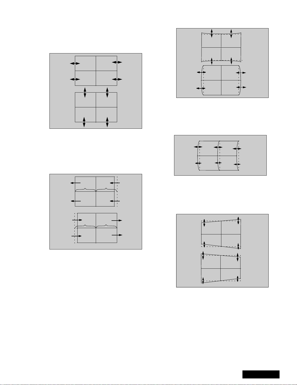
Figure 44. H&Vsizeadjustment
5. Press “7” then “ACTION” key on remote to save
changes.
6. Enter to linearity “G-LINEAR” mode by pressing
“TV/VIDEO”.
7. Adjust linearity by pressing VOL right-left until A=B
(see figure 45)
12. Press “7” then “ACTION” key on remote to save
changes.
Figure 46. H&VPINadjustment
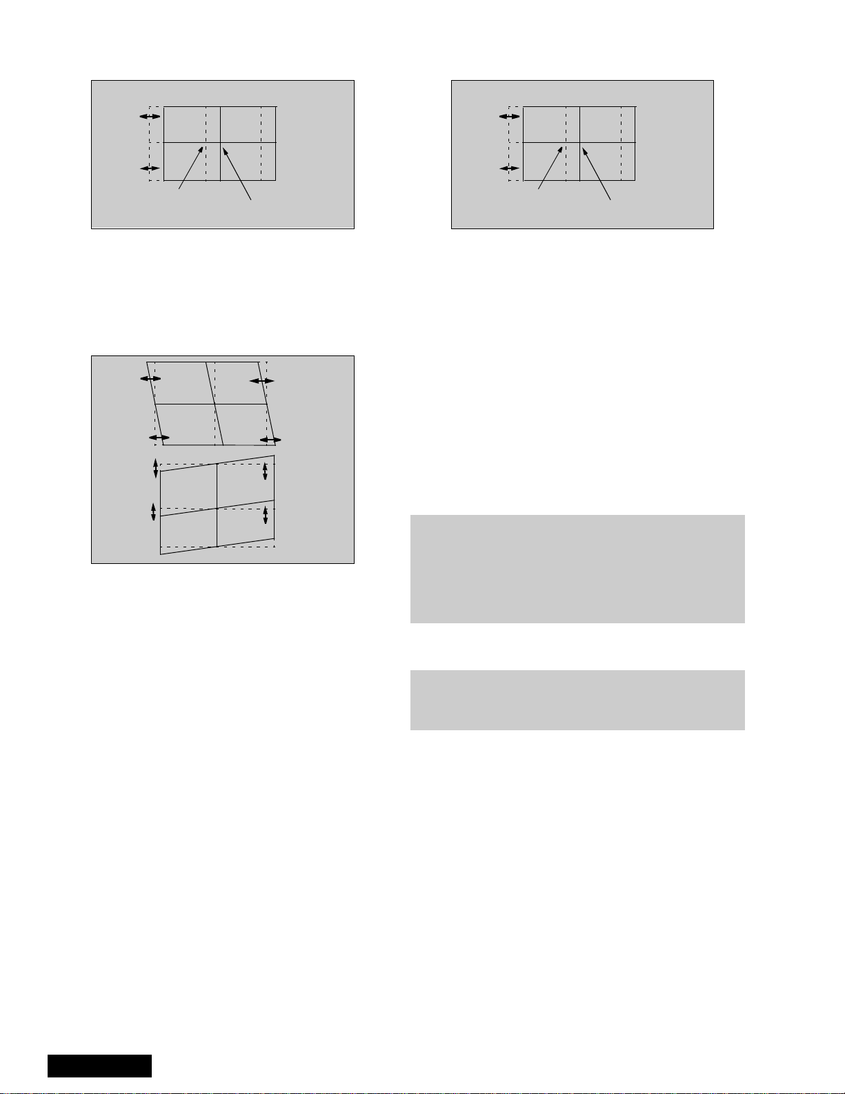
13. Enter to CORNER “G-CORNER” mode by pressing
TV/VIDEO.
14. Adjust by pressing VOL right-left (see figure 47).
15. Press “7” then “ACTION” key on remote to save
changes.
AB
AB
Figure 45. Linear mode adjustment
8. Press “7” then “ACTION” key on remote to save
changes.
9. Enter to PIN “G-PIN” mode by pressing “TV/
VIDEO”.
10. Adjust V_PIN by pressing CH up-down (see
figure 46).
11. Adjust H_PIN by pressing VOL right-left.
Figure 47. Corner adjustment
16.EntertoKEY“G-KEY”modebypressingTV/
VIDEO.
17. Adjust by pressing CH up-down (see figure 48)
18. Press “7” then “ACTION” key on remote to save
changes
Figure 48. KEY mode adjustment
Note: Confirm that pattern looks like a square and
almost overlaps the screen frame, check that
vertical and horizontal line center match with
the marks on screen frame, if linearity is not
good enough, repeat adjustments.
19. Enter to “STATIC” mode by pressing TV/VIDEO.
20. Press “1” or “3” repeatedly until green and red only
are shown.
-29-
ServiceManual
21. Adjust “R-STATIC” so that the center of red
overlaps with the center of green.
38. Adjust B-STATIC so that the center of blue
overlaps with the center of green (see figure 51).
red
Figure 49. STATIC mode adjustment
22. Enter to SKEW “R-SKEW” mode by pressing TV/
VIDEO
23. Adjust “R-SKEW” so that the vertical and horizontal
line of center overlaps with green (see figure 50)
24. Press “7” then “ACTION” key on remote to save
changes.
Figure 50. SKEW adjustment
green
Note: Remember always save data following each
adjustment by pressing “7” key on remote, then
ACTION.
25. Enter to LINEARITY “R-LINEAR” mode by
pressing TV/VIDEO.
26. Adjust Horizontal linearity (see figure 45)
27. Enter to SIZE “R-SIZE” mode by pressing TV/
VIDEO
28. Adjust so that the line on the border closes to the
screen frame at top, bottom, left and right (see
figure 44)
29. Enter to PIN “R-PIN” mode by pressing TV/VIDEO
30. Adjust horizontally and vertically (see figure 46)
31. Enter to CORNER “R-CORNER” mode by pressing
TV/VIDEO.
32. Adjust corners (see figure 47)
33. Enter to KEY “R-KEY” mode by pressing TV/
VIDEO
34. Adjust KEY (see figure 48)
35. Display pattern of border and cross, then check
that red overlaps green pattern, if it is not
satisfactory, repeat from step 19.
36. Enter to STATIC “B-STATIC” mode.
37. Press “1 or 3” key repeatedly on remote until only
green and blue pattern are displayed
blue
Figure 51. B-STATIC adjustment
39. Perform all adjustments for blue (B-SKEW, BLINEAR, B-SIZE, B-PIN, B-CORNER, B-KEY)
40. Display border and cross pattern and confirm that
blue overlaps with green pattern, if it is not
satisfactory, repeat for blue.
41. Press “1 or 3” key repeatedly on remote until
green, red and blue (white), confirm that red and
blue overlaps with green pattern.
42. Press “7” key on remote, then ACTION to save
changes.
43. Press POWER then ACTION to exit adjustments or
press TV/VIDEO for at least 3 seconds to change
to Fine Adjustment Mode.
green
Fine adjustment mode (FINE)
(convergence)
Note: It is strongly recommended to first read and
understand the following section prior to
make any adjustment.
Convergence adjustment must be perform
for 480i-p (same for interlace & progressive),
1080i and ZOOM 480i.
Helpful hint:
The easiest way to adjust convergence is to begin
from the center of the screen, to the border in all the
convergence adjustments.
Remote functions:
• 1,3............changecolorviewadj
• 2................... changepattern
• 7........................savedata
• 5......................... overlap
• POWER.....................toexit
• RECALL..............displayvalues
• R-TUNE................cyclecolors
• TV/VIDEO............ changemode
3 secs . . . . . . . . change options
• MUTE (“fine”). . . . . .cursor & data mode
About pattern:
• NTSC to adjust 480ip (same for interlace and
progressive)
• 1080i to adjust 1080i
• 480i with ptv in zoom aspect to adjust
Z480i
ServiceManual
-30-
 Loading...