

Panasonic PT-43LC14, PT-50LC14, PT-60LC14 Service Manual
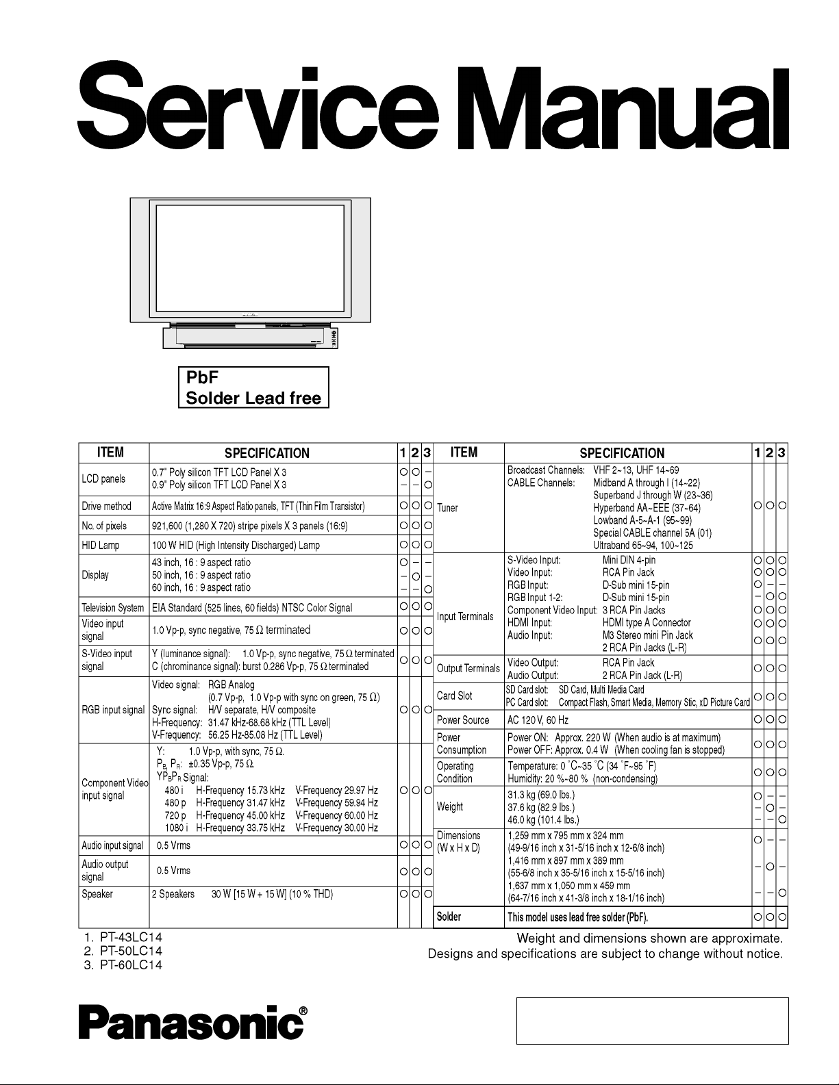
Multi Media Display
PT-43LC14
PT-50LC14
PT-60LC14
ORDER NO. MKE0406850C1
B2
© 2004 Matsushita Kotobuki Electronics Industries
LTD. All rights reserved. Unauthorized copying and
distribution is a violation of law.
PT-43LC14 / PT-50LC14 / PT-60LC14
CONTENTS
Page Page
1 SAFETY PRECAUSIONS 3
1.1. GENERAL GUIDELINES
1.2. LEAKAGE CURRENT COLD CHECK
1.3. LEAKAGE CURRENT HOT CHECK
1.4. UV-PRECAUTION
2 PREVENTION OF ELECTROSTATIC DISCHARGE (ESD) TO
ELECTROSTATICALLY SENSITIVE (ES) DEVICES
3 ABOUT LEAD FREE SOLDER (PbF)
4 SERVICE NOTES
5 DISASSEMBLY / ASSEMBLY PROCEDURES
5.1. CABINET SECTION
6 ADJUSTMENT PROCEDURES 1
7 ADJUSTMENT PROCEDURES 2
8 TROUBLESHOOTING HINTS FOR BLOCK LEVEL REPAIR
9 BLOCK DIAGRAMS
10 SCHEMATIC DIAGRAMS
10.1. SCHEMATIC DIAGRAM AND CIRCUIT BOARD LAYOUT
NOTES
10.2. INTERCONNECTION SCHEMATIC DIAGRAM
10.3. FRONT JACK SCHEMATIC DIAGRAM
10.4. NETWORK / THERMISTOR 1 / THERMISTOR 2 /
OPERATION / COVER SWITCH SCHEMATIC
DIAGRAMS
10.5. AUDIO AMP SCHEMATIC DIAGRAM
10.6. TUNER SCHEMATIC DIAGRAM
18
18
45
48
51
57
67
67
68
69
70
71
72
3
3
3
3
4
5
6
10.7. VOLTAGE CHART
11 CIRCUIT BOARD LAYOUT
11.1. FRONT JACK C.B.A. / OPERATION C.B.A. /
NETWORK C.B.A.
11.2. AUDIO AMP C.B.A. / THERMISTOR 1 C.B.A. /
THERMISTOR 2 C.B.A. / COVER SWITCH C.B.A.
11.3. TUNER C.B.A.
12 EXPLODED VIEWS
12.1. MAIN PARTS SECTION
12.2. FRONT AND BASE SECTION
12.3. DISPLAY SECTION
12.4. SCREEN SECTION
12.5. PROJECTION SECTION
12.6. TV AND TUNER SECTION
12.7. PACKING PARTS AND ACCESSORIES SECTION
12.8. OPTIONAL ACCESSORY SECTION
13 REPLACEMENT PARTS LIST
13.1. REPLACEMENT NOTES
13.2. MECHANICAL REPLACEMENT PARTS LIST
13.3. OPTIONAL ACCESSORY REPLACEMENT PARTS LIST
13.4. ELECTRICAL REPLACEMENT PARTS LIST
14 SCHEMATIC DIAGRAMS FOR PRINTING WITH LETTER SIZE
73
75
75
76
77
79
79
80
81
83
85
86
87
88
90
90
91
92
93
96
2
1 SAFETY PRECAUSIONS
1.1. GENERAL GUIDELINES
1. For continued safety, no modification of any circuit should
be attempted.
2. Disconnect AC Plug before disassembling this unit.
3. It is advisable to use an isolation transformer in the AC
supply before servicing.
4. When servicing, observe the original lead dress. If a short
circuit is found, replace all parts which have been
overheated or damaged by the short circuit.
5. After servicing, see to it that all the protective devices such
as insulation barriers, insulation papers, shield, and
isolation R-C combinations etc. are properly installed.
6. After servicing, be sure to restore the wires, leads,
insulation barriers, shields, etc.
7. After servicing, make the leakage current checks to prevent
the customer from being exposed to shock hazards.
Caution:
Use a separate Isolation Transformer for this unit when
servicing.
1.2. LEAKAGE CURRENT COLD
CHECK
1. Unplug the AC cord and connect a jumper between the two
prongs on the plug.
2. For physically operated power switches, turn power on.
Otherwise skip step 2.
3. Measure the resistance value, with an ohmmeter, between
the jumpered AC plug and each exposed metallic cabinet
part on the receiver, such as screwheads, connectors, etc.
When the exposed metallic part has a return path to the
chassis, the readingshouldbebetween 1 MΩ and 12 MΩ.
When the exposed metal does not have a return path to the
chassis, the reading must be infinity.
PT-43LC14 / PT-50LC14 / PT-60LC14
not exceed 1/2 mA. In case a measurement is outside of
the limits specified, there is a possibility of shock hazard,
and thereceivershouldbe repaired and rechecked before it
is returned to the customer.
Figure 1
1.4. UV-PRECAUTION
1. Be sure to disconnect the AC Plug when replacing the
lamp.
2. Since the lamp reaches a very high temperature during its
operation, wait until it has completely cooled off when
replacing the Lamp Unit.
3. The lamp emits small amounts of UV-Radiation.
Avoid direct-eye contact by covering the Lamp and wearing
the UV cut protective glass.
4. The high pressure lamp involves a risk of explosion.
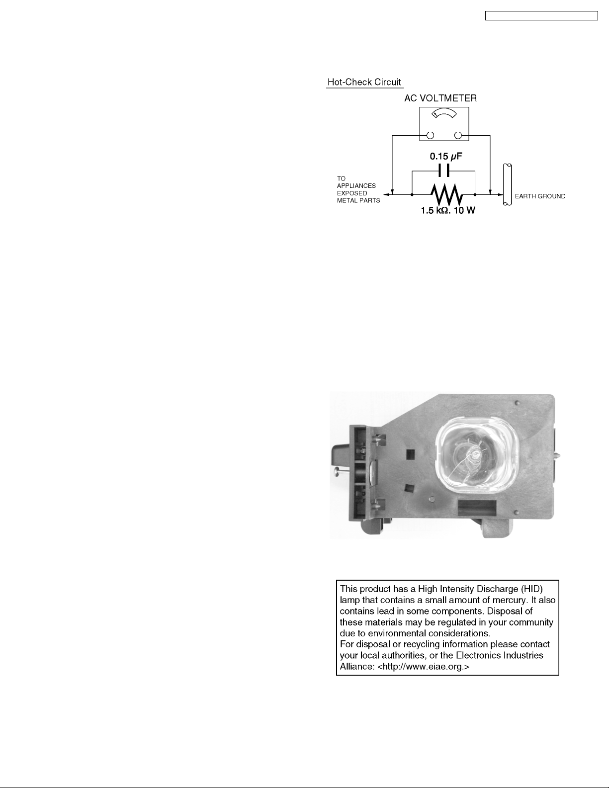
1.3. LEAKAGE CURRENT HOT
CHECK
1. Plug the AC cord directly into the AC outlet.
Do not use a isolation transformer for this check.
2. Connect a 1.5 kΩ, 10 W resistor, in parallel with a 0.15 µF
capacitor, between each exposed metallic part on the set
and a good earth ground, as shown in Figure 1.
3. Use an AC voltmeter, with 1 kΩ/V or more sensitivity, to
measure the potential across the resistor.
4. Check each exposed metallic part, and measure the
voltage at each point.
5. Reverse the AC plug in the AC outlet and repeat each of the
above measurements.
6. The potential at any point should not exceed 0.75 V RMS.
A leakage current tester (Simpson Model 229 equivalent)
may be used to make the hot checks. Leakage current must
Figure 2
3

PT-43LC14 / PT-50LC14 / PT-60LC14
2 PREVENTION OF
ELECTROSTATIC
DISCHARGE (ESD) TO
ELECTROSTATICALLY
SENSITIVE (ES) DEVICES
Some semiconductor (solid state) devices can be damaged
easily by static electricity. Such components commonly are
called Electrostatically Sensitive (ES) Devices. Examples of
typical ES devices are integrated circuits and some field-effect
transistorsandsemiconductor"chip" components. The following
techniques should be used to help reduce the incidence of
component damage caused by electro static discharge (ESD).
1. Immediately before handling any semiconductor
component or semiconductor-equipped assembly, drain off
any ESD on your body by touching a known earth ground.
Alternatively, obtain and wear a commercially available
discharging ESD wrist strap,whichshouldbe removed for
potential shock reasons prior to applying power to the unit
under test.
2. After removing an electrical assembly equipped with ES
devices, place the assembly on a conductive surface such
as aluminum foil, to prevent electrostatic charge buildup or
exposure of the assembly.
3. Use only a grounded-tip soldering iron to solder or unsolder
ES devices.
4. Use only an antistatic solder removal device. Some solder
removal devices not classified as "antistatic (ESD
protected)" can generate electrical charge sufficient to
damage ES devices.
5. Do not use freon-propelled chemicals. These can generate
electrical charges sufficient to damage ES devices.
6. Do not remove a replacement ES device from its protective
package until immediately before you are ready to install it.
(Most replacement ES devices are packaged with leads
electrically shorted together by conductive foam, aluminum
foil or comparableconductivematerial).
7. Immediately before removing the protective material from
the leads of a replacement ES device, touch the protective
material to the chassis or circuit assembly into which the
device will be installed.
CAUTION :
Be sure no power is applied to the chassis or circuit, and
observe all other safety precautions.
8. Minimize bodily motions when handling unpackaged
replacement ES devices. (Otherwise harmless motion such
as the brushing together of your clothes fabric or the lifting
of your foot from a carpeted floor can generate static
electricity (ESD)sufficienttodamage an ES device).
4
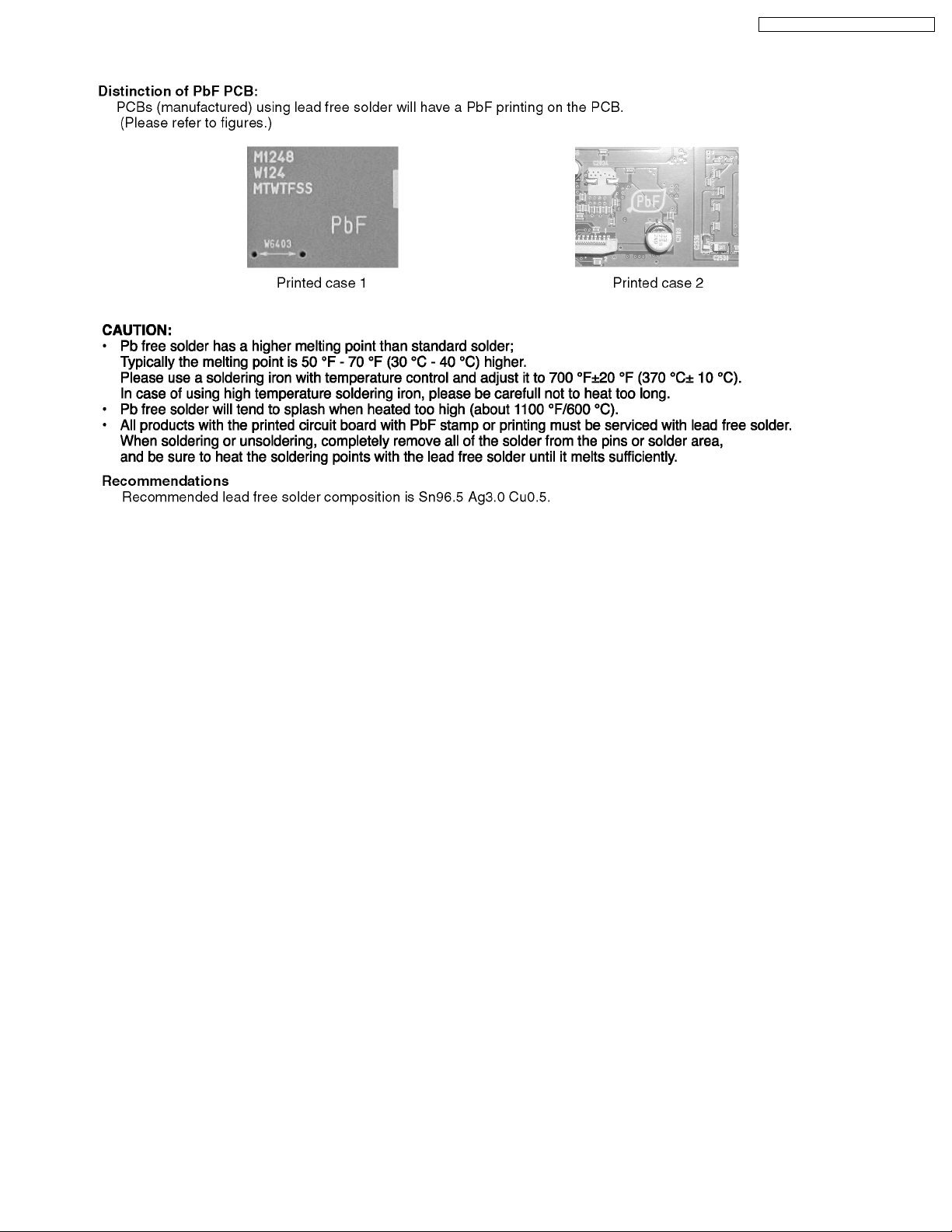
3 ABOUT LEAD FREE SOLDER (PbF)
PT-43LC14 / PT-50LC14 / PT-60LC14
5
PT-43LC14 / PT-50LC14 / PT-60LC14
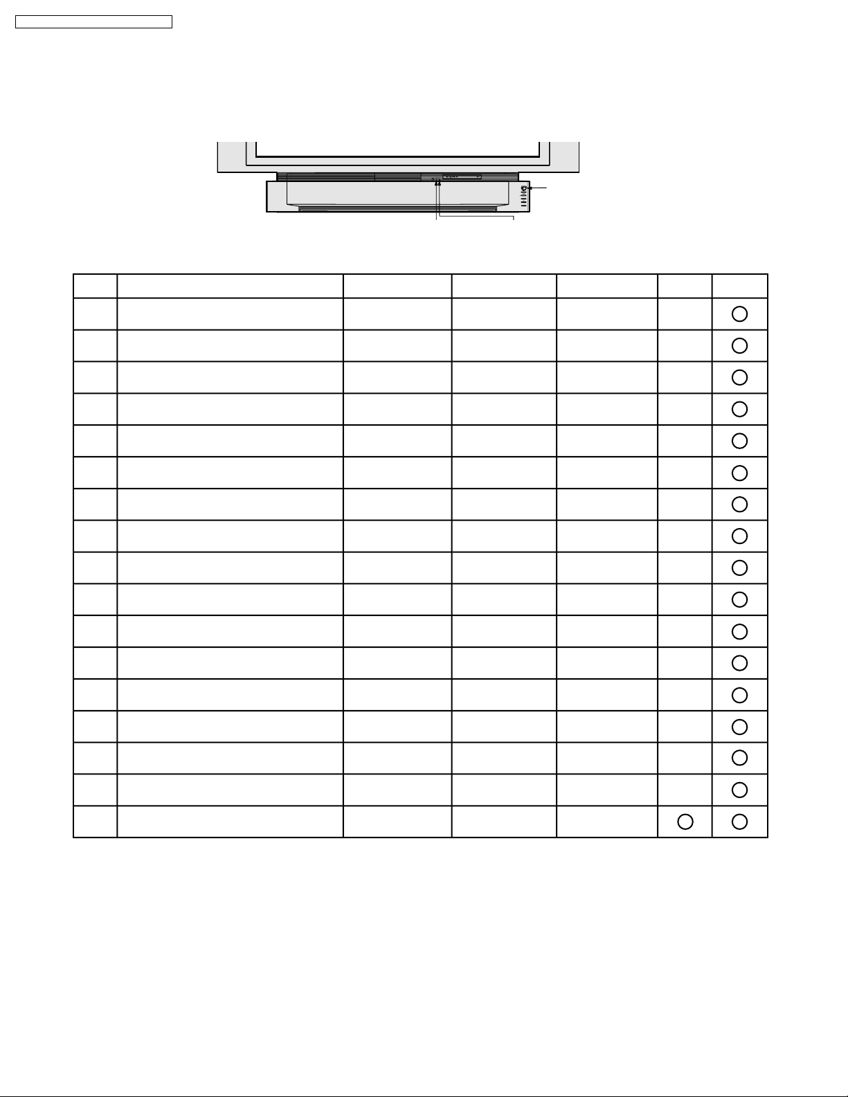
4 SERVICE NOTES
LED INDICATIONS FOR ERROR CONDITION
Each LED indication facilitates finding the cause of the error.
When an error is detected, the Lamp comes off and the LED on the front will flash.
POWER LED
TV/VIDEO
TEMP LED
LAMP LED
(Note 2) (Note 3)
Error InformationError No. LAMP OFFLAMP LED OSD
1)
Fan1, Fan2 or Fan3 stopped
Lamp Cover open
2)
Temperature Sensor shorted or open
3)
(Thermistor 1 C.B.A.)
Abnormal Temperature
4)
(Thermistor 1 C.B.A.)
Ballast Error (abnormal Lamp or Ballast)
5)
Ballast Error (abnormal Lamp voltage)
6)
Ballast Error (abnormal temperature)
7)
Ballast Error (other causes)
8)
Abnormal Voltage on 30 V line
9)
10)
Abnormal Voltage on 9 V line
Abnormal Voltage on 5 V line
11)
Abnormal Voltage on 3.3 V line
12)
Abnormal Voltage on -5 V line
13)
Abnormal Voltage on 6 V line
14)
Temperature Sensor shorted or open
15)
(Thermistor 2 C.B.A.)
16)
Abnormal Temperature
(Thermistor 2 C.B.A.)
Clogged air filter
17)
flashes orange once
every 5 seconds
flashes orange twice
every 5 seconds
-
--
-
-
-
flashes orange 5 times
every 5 seconds
flashes orange 6 times
every 5 seconds
flashes orange 7 times
every 5 seconds
flashes orange 8 times
every 5 seconds
flashes orange 9 times
every 5 seconds
flashes orange 10 times
every 5 seconds
-
-
-
TEMP LEDPOWER LED
--
-
flashes once
every 5 seconds
flashes twice
every 5 seconds
--
-
-
-
flashes once
every 5 seconds
flashes twice
every 5 seconds
flashes 3 times
every 5 seconds
flashes 4 times
every 5 seconds
flashes 5 times
every 5 seconds
flashes 6 times
every 5 seconds
flashes 3 times
every 5 seconds
flashes 4 times
every 5 seconds
flashes 5 times
every 5 seconds
-
-
flashes once
every 5 seconds
flashes twice
every 5 seconds
flashes 3 times
every 5 seconds
flashes 4 times
every 5 seconds
flashes once
every 5 seconds
flashes twice
every 5 seconds
flashes 3 times
every 5 seconds
flashes 4 times
every 5 seconds
flashes 5 times
every 5 seconds
flashes 6 times
every 5 seconds
-
-
-
Note:
1. When two or more errors have occurred at the same time, the LED will alternate flash patterns as shown above every 5 seconds.
2. Warning OSD appears when the air filter is clogged.
3. LAMP OFF: The LED will flash immediately after the Lamp comes off.
6
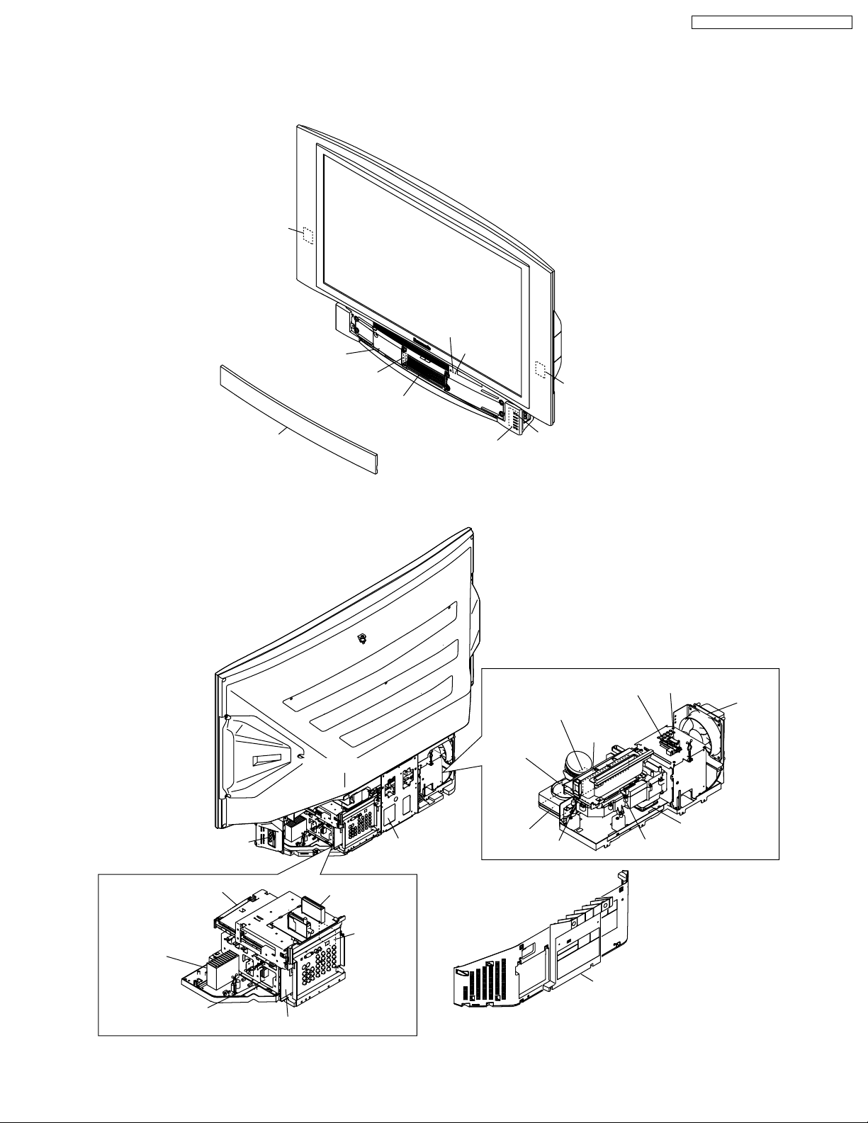
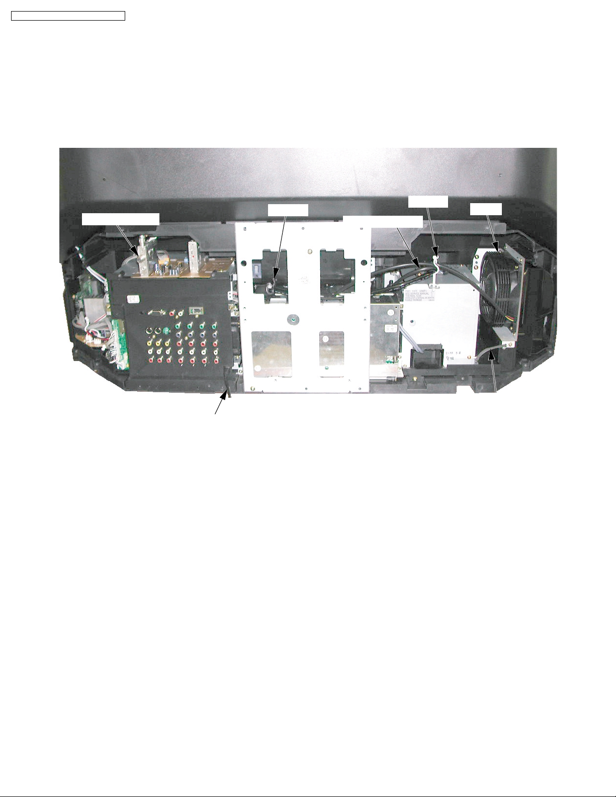
MAIN PARTS LOCATION
Network C.B.A.
<Front View>
Lamp Cover
Cover Switch C.B.A.
Optical Cover
PT-43LC14 / PT-50LC14 / PT-60LC14
TEMP LED
LAMP LED
Network C.B.A.
Front Cover Unit
Front Jack C.B.A.
Operation C.B.A.
<Rear View>
Ballast C.B.A.
POWER LED
Projection Unit
Thermal Fuse Unit
Thermistor 1 C.B.A.
Air Filter
Fan Case Unit
(Fan 1)
Air Filter
Air Filter
Thermistor 2 C.B.A.
Fan 3
Fan 2
LCD Drive C.B.A.
Audio
Amp C.B.A.
Power C.B.A.
Main C.B.A.
Tuner C.B.A.
Fan 4
Rear Cover
Rear Jack C.B.A.
TV/Tuner Unit
7
PT-43LC14 / PT-50LC14 / PT-60LC14
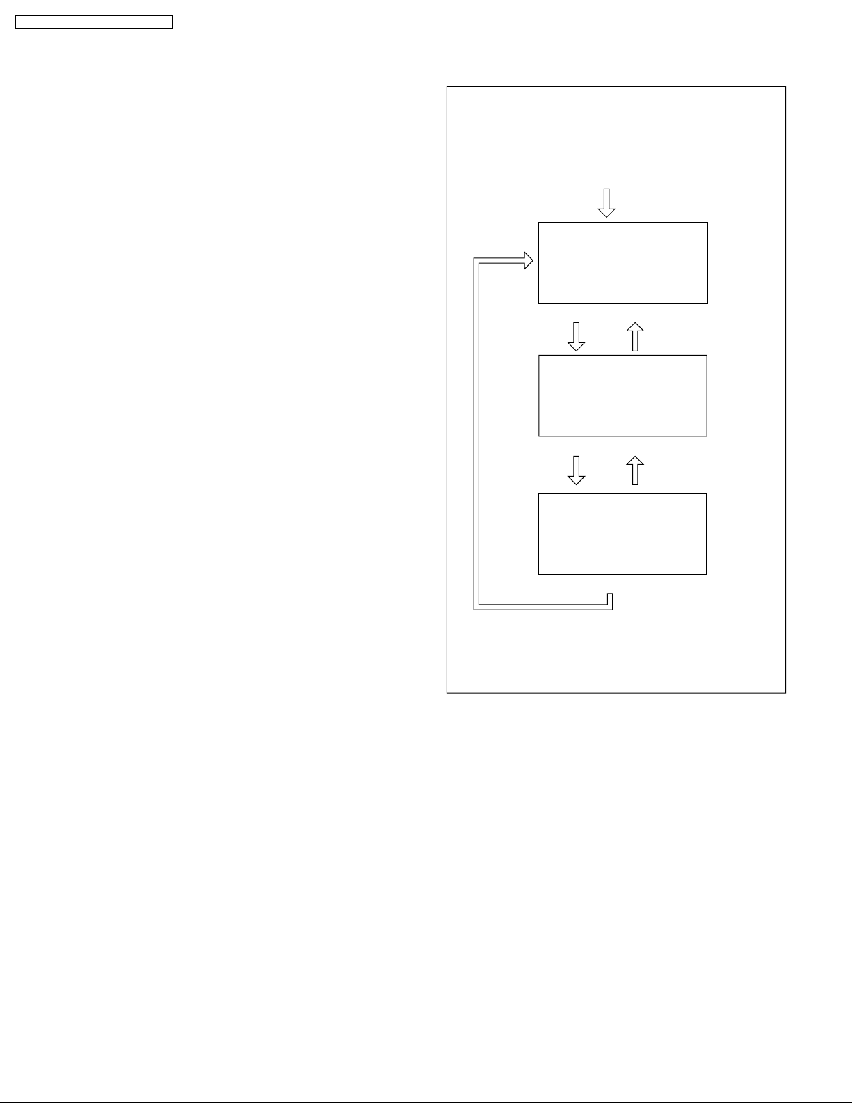
SERVICE MODE
In this mode, the following information can be confirmed on the
screen:
Service Mode (1/3)
• Current Lamp elapsed time
• The number of Lamp ON (For reference only)
• BKSV number read-out
Service Mode (2/3)
• Key detection check
• Communication check for IIC bus and serial bus on the
Main C.B.A.
• Total Lamp elapsed time
• Communication check for IIC bus on the Main C.B.A.
• EEPROM IC6006 version and build version
• EEPROM IC6306 version and build version
• IC6003 software version and build version
• IC6302 software version and build version
Service Mode (3/3)
• IC6003 Port information
• IC6302 Port information
Note:
IC6003: Main Microcontroller on the Main C.B.A.
IC6302: Sub Microcontroller on the Main C.B.A.
(For reference only)
(For reference only)
(For reference only)
(For reference only)
Service Mode Map
Enter :
VOLUME DOWN button + TV/VIDEO key
(on the front) (on the remote)
(for more than 5 seconds in power off condition)
Power ON
SERVICE MODE 1/3
LAMP OPERATION TIME
CURRENT LAMP: 2000h
OSD DISPLAY : ON
LON COUNT : 153
BKSV: 4B 7E 3D CA FB
< Service Mode (1/3) >
CH DOWN key CH UP key
SERVICE MODE 2/3
IR:1 UNIT:1
IC3501:1 3502:1 3504:1
5004:1 5103:1 5301:1
6005:1 6006:1 9004:1
TOTAL 12345h
IC7501:1 MTNR:1 STNR:1
E:040525
F:0000000
IC6003 V:0405252
IC6302 V:0405200
< Service Mode (2/3) >
CH DOWN key
SERVICE MODE P6:00000011 3/3
IC6003 PORT P3:00000000
P0:00001110 P4:10000010
P1:10000001 P5:10111000
P2:11111111 P7:10010000
IC6302 PORT P8:11101111
P0:001-1111 P5:-----001
P1:-0-0-1-1 P6:11011001
P2:---00111 P7:11001100
P3:00000111 P8:----0111
P4:11110011 PA:----1111
< Service Mode (3/3) >
CH UP key
Exit:
CH DOWN key
Power OFF.
(When turning the power on again after once turning
off, wait for approx. 10 seconds. Or, the unit can not be
released from Service Mode.)
Fig. 1-1
8
Value A
(Changeable)
<Service Mode (1/3)>
SERVICE MODE 1/3
LAMP OPERATION TIME
CURRENT LAMP: 2000h
OSD DISPLAY : ON
LON COUNT : 153
BKSV: B0 3A 59 CD 66
PT-43LC14 / PT-50LC14 / PT-60LC14
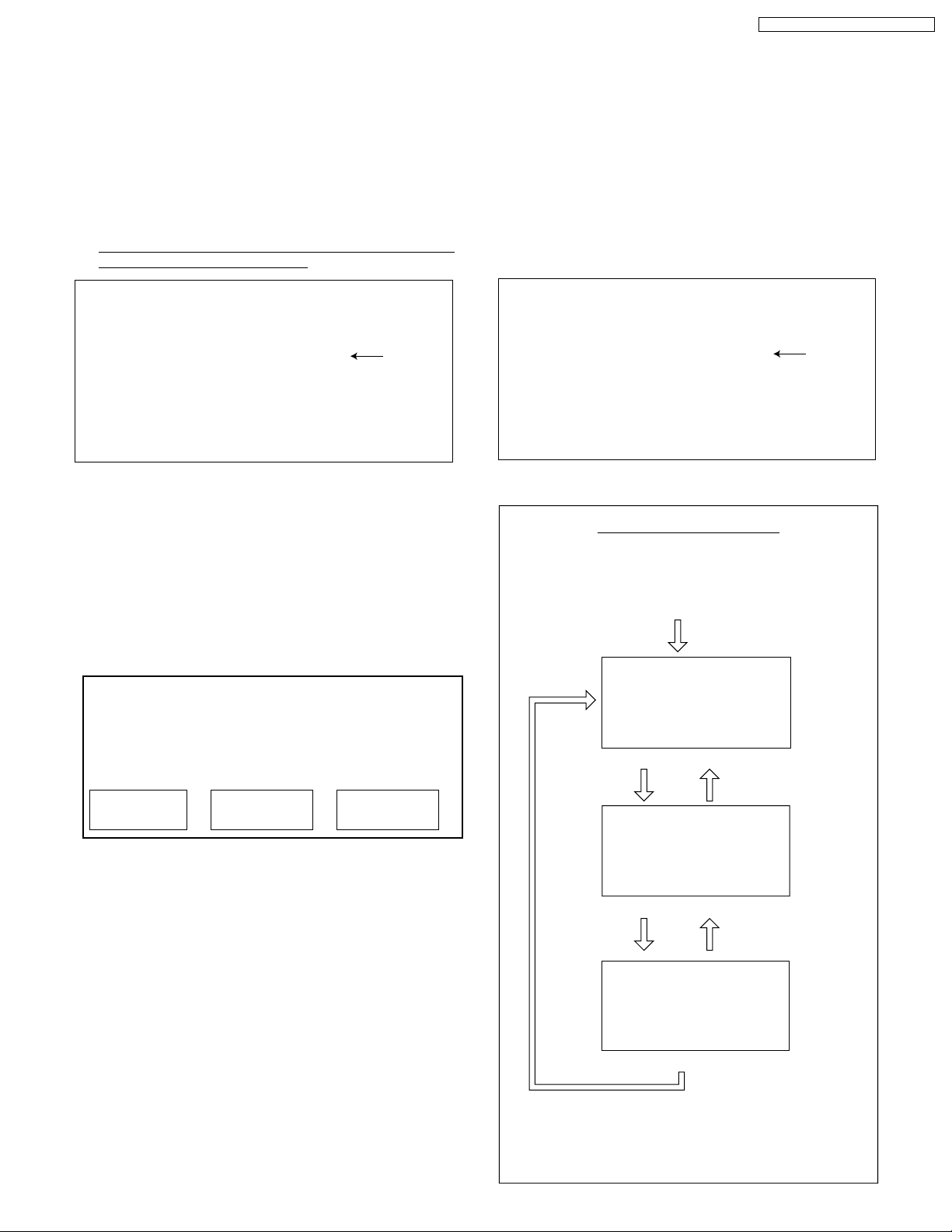
BEFORE REMOVING THE MAIN C.B.A. OR
THE TV/TUNER UNIT FROM THE UNIT AT
THE USER’S LOCATION
Note:
The TV/Tuner Unit includes the Main C.B.A.
CAUTION:
Be sure to make a note of the CURRENT LAMP value
1.
(value A) in Service Mode (1/3):
SERVICE MODE 1/3
LAMP OPERATION TIME
CURRENT LAMP: 2000h
OSD DISPLAY : ON
LON COUNT : 153
BKSV: 4B 7E 3D CA FB
<Service Mode (1/3)>
Fig. 2
LAMP OPERATION TIME is stored in EEPROM on the
Main C.B.A. Therefore, before removing the Main C.B.A. or
the TV/Tuner Unit at the user’s location, make a note of the
CURRENT LAMP value (value A) in Service Mode (1/3).
Then, after installing the new Main C.B.A. or the TV/Tuner
Unit at the user’s location, set the CURRENT LAMP value
to the original value (value A) in Service Mode.
Otherwise, OSD and LED Lamp replacement indications
will be displayed at the wrong time.
Note:
In case it is impossible to make a note of the CURRENT
LAMP value because of a defective Main C.B.A., ask the
customer their daily average use and the approximate age
of the current Lamp. Then, calculate the CURRENT LAMP
value as follows and make a note.
Value A
(Changeable)
WHEN REINSTALLING THE MAIN C.B.A.
OR THE TV/TUNER UNIT INTO THE UNIT
AT THE USER’S LOCATION
CAUTION:
1. Set CURRENT LAMP value to original value as follows.
1) Select CURRENT LAMP in Service Mode (1/3).
2) Press the VOLUME UP/DOWN key on the remote to
change to the original value (value A) that was noted
before removing the Main C.B.A. or the TV/Tuner Unit
at the user’s location.
Fig. 3
Service Mode Map
Enter :
VOLUME DOWN button + TV/VIDEO key
(on the front) (on the remote)
(for more than 5 seconds in power off condition)
Power ON
SERVICE MODE 1/3
LAMP OPERATION TIME
CURRENT LAMP: 2000h
OSD DISPLAY : ON
LON COUNT : 153
BKSV: 4B 7E 3D CA FB
< Service Mode (1/3) >
CH DOWN key CH UP key
Daily average use
(hours) (days) (hours)
Approx. age CURRENT LAMP
X=
Note:
The TOTAL value can be set to the original value in Service
Mode (2/3) by similar method:
Before removing the Main C.B.A. at the user’s location,
make a note of the TOTAL value in Service Mode (2/3).
Then, after installing the new Main C.B.A. at the user’s
location, set the TOTAL value to the original value in
Service Mode.
SERVICE MODE 2/3
IR:1 UNIT:1
IC3501:1 3502:1 3504:1
5004:1 5103:1 5301:1
6005:1 6006:1 9004:1
TOTAL 12345h
IC7501:1 MTNR:1 STNR:1
E:040525
F:0000000
IC6003 V:0405252
IC6302 V:0405200
< Service Mode (2/3) >
CH DOWN key
Exit:
SERVICE MODE P6:00000011 3/3
IC6003 PORT P3:00000000
P0:00001110 P4:10000010
P1:10000001 P5:10111000
P2:11111111 P7:10010000
IC6302 PORT P8:11101111
P0:001-1111 P5:-----001
P1:-0-0-1-1 P6:11011001
P2:---00111 P7:11001100
P3:00000111 P8:----0111
P4:11110011 PA:----1111
< Service Mode (3/3) >
CH UP key
CH DOWN key
Power OFF.
(When turning the power on again after once turning
off, wait for approx. 10 seconds. Or, the unit can not be
released from Service Mode.)
9
PT-43LC14 / PT-50LC14 / PT-60LC14
REPLACEMENT OF LAMP
Lamp Time Reset Procedure:
Be sure to reset the Lamp time to "0" after replacing the new
Lamp.
1. Plug in the AC Cord, and turn on the power by pressing the
POWER button.
2. Press and hold the VOLUME DOWN button on the unit and
the SPLIT key on the remote together for over 5 seconds in
power on condition.
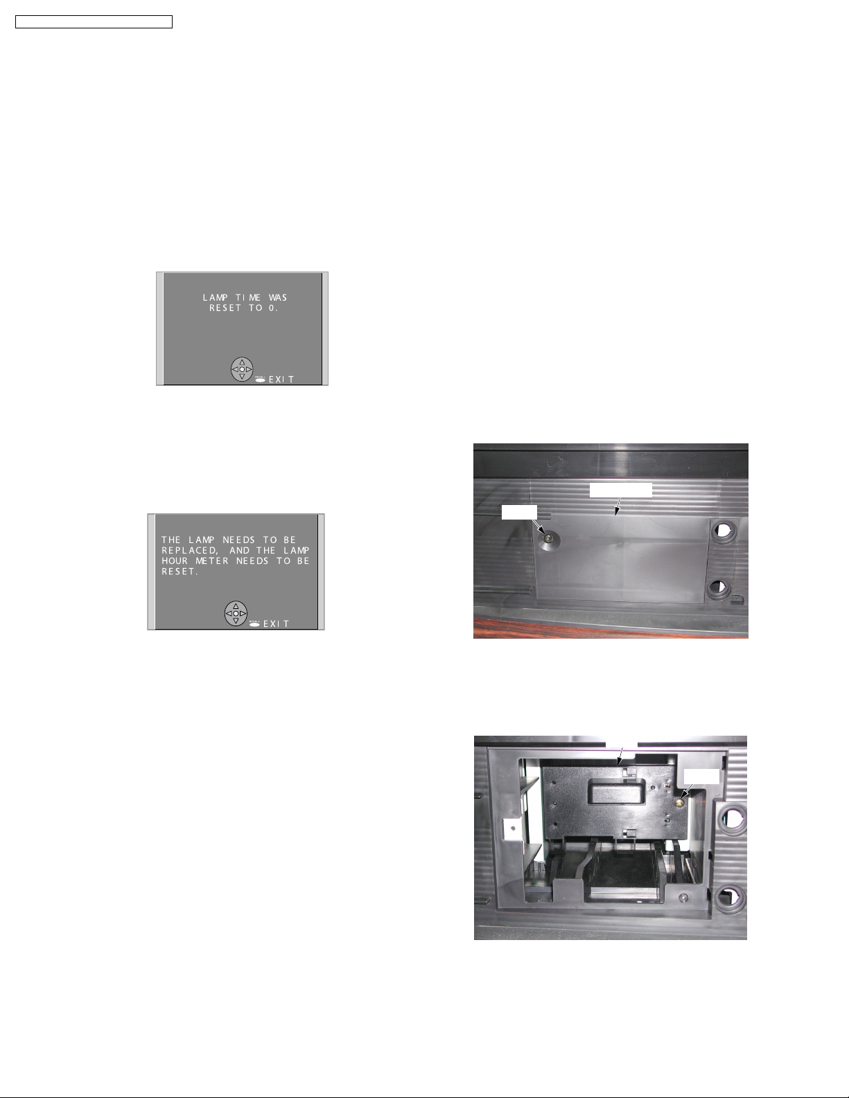
When the reset is finished, the display as shown in Fig. 51 appears and the LAMP LED goes out.
Fig. 5-1
Note:
1. The unit will detect when the Lamp’s end of life is
approaching and the following message will be
displayed. And the LAMP indicator light will be lit when
the Lamp’s end of life is approaching.
Lamp Replacement Procedure:
1. Press the POWER button on the remote to turn off the
power.
2. Wait for about 1 minute until the cooling fan stops.
Note:
The lamp cooling fan will continue to operate for about 1
minute after the power is turned off. Do not unplug the AC
Cord from the outlet until the fan has stopped. Avoid
interrupting the power by using circuit breakers or switchable
power strips.
3. After the cooling fan has stopped, unplug the AC Cord from
the outlet.
Note:
Please wait more than one hour before replacing the lamp.
[ Forced cooling function ]
If you need to replace the lamp more urgently:
• The Projection display has a forced cooling feature.
After the POWER button is turned OFF, and sometime
during about the first minute of the normal cooling fan
operation, press the VOLUME UP button on the unit
and CH UP key on the remote at the same time for more
than 5 seconds. The cooling fan will operate for about
10 minutes. (LAMP LED will flash 5 times every 5
second and POWER LED will flash red for 10 minutes.)
4. Remove the Front Cover Unit from the latches.
5. Remove the Lamp Cover by loosening the Screw.
Lamp Cover
Screw
Fig. 5-2
2. Influences of frequent lighting, continuous light use for
over 24 hours, the number of times lit, the length of time
between lightings, etc. may shorten lamp life. (Because
of this, we recommend having a replacement lamp on
hand.)
WARNING:
• The high-pressure lamp could explode if not properly
handled and lamp fragments could cause injury.
• Because the temperature of the lamp unit is elevated
immediately after its use, touching it may cause burns.
Please allow the lamp to cool before handling or replacing
the lamp unit.
• Wear gloves and safety eyeglasses when replacing the
lamp unit.
• If replacement of the lamp unit becomes necessary during
the operation of the TV, follow the procedure to turn off the
power and wait until the lamp unit cools completely.
Cautions for Lamp Unit Replacement:
• Do not disassemble the Lamp.
• The lamp may be hot. Be careful when handling. Wear
gloves.
• Under no circumstance should you touch the actual bulb.
At this high operating temperature the natural oil on your
finger can cause the glass to weaken where touched and
the bulb can crack or explode.
Fig. 5-3
6. Loosen the Screw on the Lamp. Then, pull the Lamp.
Note:
Because the Lamp may still be hot, use caution when
handling.
Lamp
Screw
Fig. 5-4
7. Install the new Lamp, and tighten the Screw.
8. Install the Lamp Cover securely, and tighten the Screw.
9. Install the Front Cover Unit.
Note:
After replacing the Lamp, use caution to reset the Lamp time.
10
ping
PT-43LC14 / PT-50LC14 / PT-60LC14
CLEANING METHOD
THE SCREEN UNIT AND THE MIRROR
•THE SCREEN UNIT (Lenticular Screen, Fresnel Lens)
It is strongly recommended that the Lenticular Screen surface
(outside) and the Fresnel Lens surface (inside) should be
wiped gently with a clean, soft, dry cloth to remove the dirt.
Note:
1. If the dirt cannot be removed by wiping with a clean, soft, dry
cloth, use a clean, soft, dry cloth moistened with diluted
neutral pH liquid cleanser or a lens cleaner (usually
containing a small amount of ethyl alcohol) and wipe lightly.
Take care not to leave any streaks.
Do not use cleaning materials containing methyl alcohol,
acetone, or dichloromethane.
2. Use an air blower to clean the inner surface of the Lenticular
Screen and the outer surface of the Fresnel Lens (the
surfaces that one another). These surfaces must not be
wiped with a cloth.
•THE MIRROR
Remove any dirt with an air blower or wipe with a clean, soft,
dry cloth. If wiped too forcefully, the surface of the Mirror can
be damaged. If wiping with a clean, dry cloth does not remove
the dirt, the Mirror must be replaced.
Mirror
THE FILTER ON THE PROJECTION UNIT
CAUTION:
Operating with torn or damaged Air Filter may cause damage
to the Projection unit.
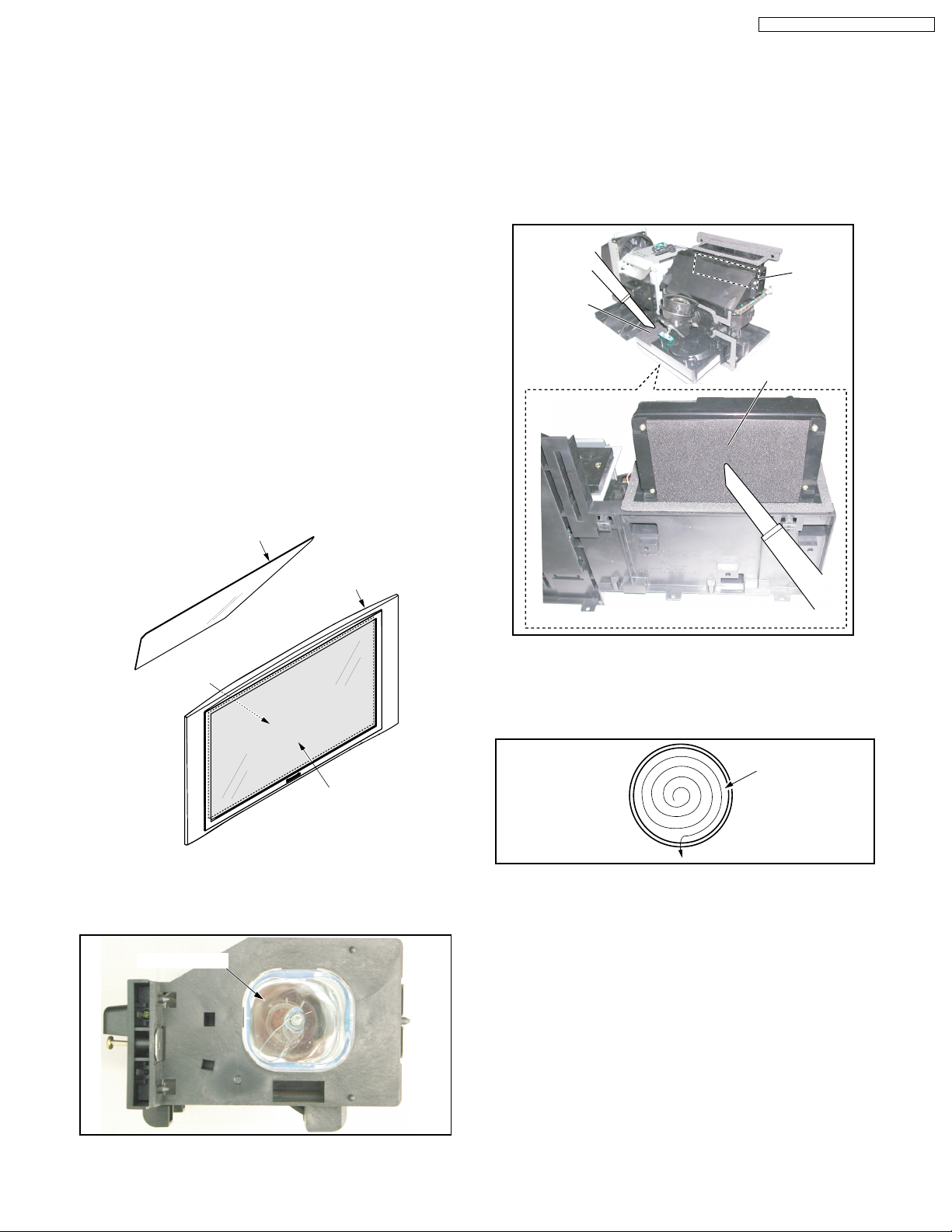
Remove the Projection Unit from rear. Then, clean the filters on
the Projection Unit. Gently remove any accumulated dust from
filter with a vacuum cleaner.
Air Filter
Air Filter
Air Filter
Screen Unit
Fresnel Lens surface
(inside)
Lenticular Screen surface
(outside)
Fig. 6-1
THE LAMP
Gently wipe the surface of the glass of the Lamp with cleaning
paper or soft cloth.
Surface of glass
<Bottom View>
Fig. 6-3
THE PROJECTION LENS
Use lens cleaning paper and cleaner available at your local
camera shop, etc. Dampen the cleaning paper with cleaner
and gently wipe the surface of the lens from the center outward
to remove dust.
Lens
Fig. 6-4
THE POLARIZER UNIT, THE FIELD LENS, THE RELAY
LENS, THE CONDENSER LENS, THE DICHROIC
MIRROR, THE FULL MIRRORS, THE INTEGRATOR AND
THE P/S CONVERTER
Make sure that no dust gets on the optical components such as
the Polarizer Unit, the Field Lens, the Relay Lens, the Condenser
Lens, the Dichroic Mirror, the Full Mirrors, the Integrator and
the P/S Converter. Clean these optical components with
cleaning paper moistened with pure ethyl alcohol or a lens
cleaner which contains no water or oil.
Fig. 6-2
THE LCD PANEL OF THE LCD/PRISM UNIT
1) Clean the surface of the LCD Panel of the LCD/Prism Unit
with an air blower or wipe with a clean, or soft blush lightly.
2) If any dirt remains, lightly wipe the surface with a cotton
swab moistened with pure ethyl alcohol or a lens cleaner
which contains no water or oil. Use a new swab after each
so that dirt will not be re-deposited on the surface.
wi
11
PT-43LC14 / PT-50LC14 / PT-60LC14
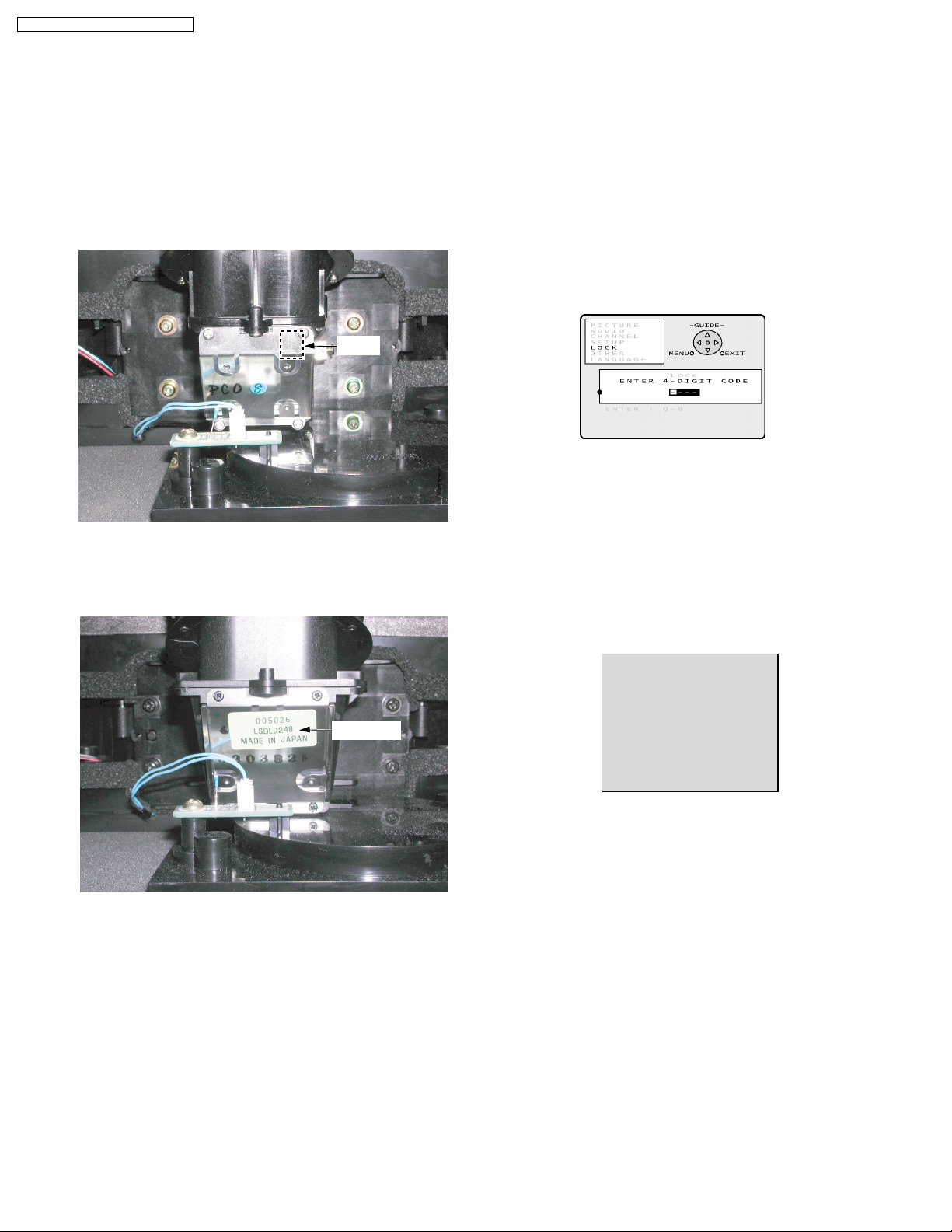
TO DISTINGUISH THE PROJECTION
LENS UNIT OR THE PROJECTION UNIT
The only difference between the 43 inch model and the 50 inch
model of the Projection Unit is the Projection Lens. To
distinguish, see marking (Z or A) on the Projection Lens.
And the 60 inch model of the Projection Unit is placed label on
the Projection Lens.
43/50 inch model as shown
X X X A
<Front View>
Z with red: for 43 inch model
A with black: for 50 inch model
60 inch model as shown
Z or A
RESET USER’S MEMORY FUNCTIONS
Be sure to reset the user’s memory:
• After replacing the Main C.B.A. (included in the TV/Tuner
Unit)
• If the secret code of V-chip is forgotten.
• When moving the unit to a new location.
1. Turn on the power.
2. Press the MENU key on the remote to display the MENU
screen.
3. Select LOCK by pressing CH UP/DOWN key on the remote.
Then, press the OK key.
4. Press and hold the VOLUME DOWN button on the unit and
the OK key on the remote for more than 5 seconds while this
LOCK menu is displayed. When reset is finished, power
shuts off automatically (the user’s memory is reset).
CLOGGED AIR FILTER DETECTION
When a dirty or clogged air filter is detected, the OSD display
appears for 1 minute. And then the Lamp is turned OFF.
When this OSD display appears, remove the Projection Unit
from rear, and clean the air filters gently on the Projection Unit.
LSDL0248
<Front View>
LSDL0248 with Yellowish green label: for 60 inch model
Note:
LSDL0248 is not the part numbers of the Projection Lens as a
replacement part.
AIR FILTER CLEANING
IS RECOMMANDED AT THIS
TIME. FIRST TURN THE
UNIT OFF.
PLEASE CALL FOR
SERVICE.
UNIT WILL BE TURNED
OFF AFTER 1 MINUTE.
12
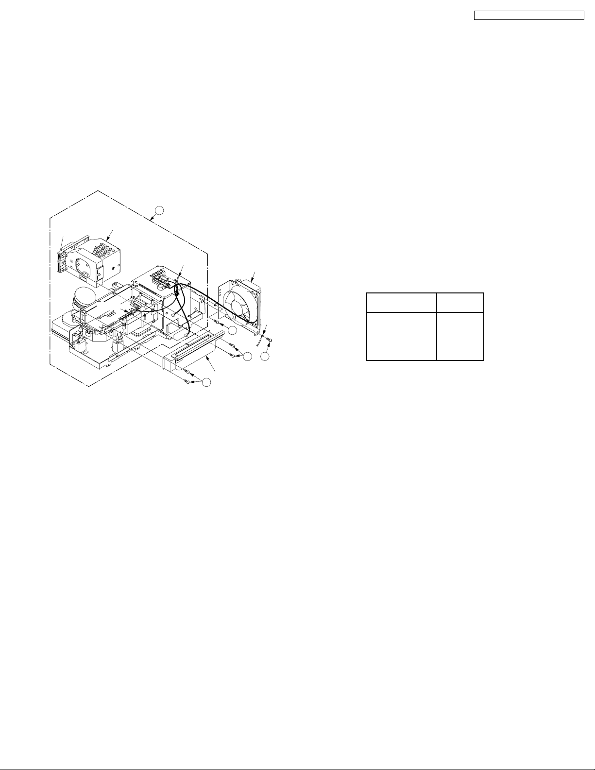
MODEL
PT-43LC14
PT-50LC14
PT-60LC14
NOT USED
MARK
A
B
C
PT
Note:
Refer to Item 3 of Schematic Diagram Notes of
Schematic Diagram and Circuit Board Layout Notes,
for mark "PT."
PT-43LC14 / PT-50LC14 / PT-60LC14
BEFORE REMOVING THE PROJECTION
UNIT FROM THE UNIT AT THE USER’S
LOCATION
1. When removing the Projection Unit, remove the Lamp from
the Projection Unit and keep it. Then, reinstall this Lamp
into the new Projection Unit.
2. When removing the Projection Unit, remove the Fan 3 Unit,
the Top Duct 3 Unit and the 20-pin Cable from the Projection
Unit and keep them. Then, reinstall the Fan 3 Unit, the Top
Duct 3 Unit and the 20-pin Cable into the new Projection
Unit.
21
Projection Unit
Screw
for lamp
Lamp
P2904
Clamper
Fan 3 Unit
GND
Wire
402
DO NOT UNPLUG AC CORD DURING
COOLING OPERATION
The lamp cooling fan will continue to operate for approximately
1 minute after the power is turned off.
At the same time, the POWER LED will flash red.
Do not disconnect the AC Cord from the power outlet and do
not open any circuit breakers while the cooling fan is still
operating.
HOT CIRCUIT
Primary circuit exists on the Audio Amp C.B.A., the Ballast
C.B.A. and the Power C.B.A.
This circuit is identified as "HOT" on the C.B.A. and in the
Service Manual. Use extreme care to prevent accidental shock
when servicing.
MODEL NO. IDENTIFICATION MARK
Use Marks shown in the chart below to distinguish the different
models included in this Service Manual.
Top Duct 3 Unit
421
421
402
13
PT-43LC14 / PT-50LC14 / PT-60LC14
WIRE AND LEAD POSITION DIAGRAM OF THE UNIT
After servicing, make sure that all wires, leads, and clampers are placed in their original position. It is important for the best
operation of the unit.
Note: Use extreme care especially for the following.
RF Input Terminal
AC Cord
Clamper
Fig. 9-1
Clamper
Thermal Fuse Unit
Fan 3
GND Wire
14
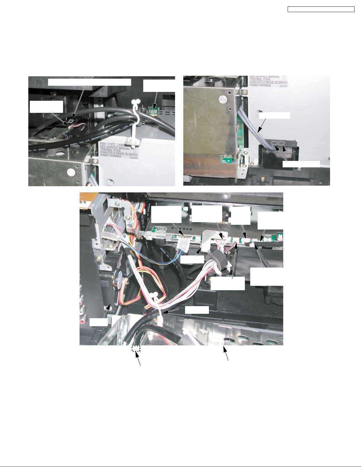
PT-43LC14 / PT-50LC14 / PT-60LC14
After servicing, make sure that all wires, leads, and clampers are placed in their original position. It is important for the best
operation of the unit.
Note: Use extreme care especially for the following.
P2303 (From Thermistor 1 C.B.A.)
P2902
(From Fan 1)
Thermistor 2
C.B.A.
P2501
(From Main
C.B.A.)
P2901
(From Main
C.B.A.)
P2904
(From
Fan 3)
Lamp Cable
Lamp Sockets
P2502 (From
Cover Switch
C.B.A.)
Fan 4
Clamper
P1306 (From Thermal Fuse Unit)
Fig. 9-2
Clamper
P2903
(From Fan 2)
Ballast C.B.A.
P2304 (From
Thermistor 2
C.B.A.)
15
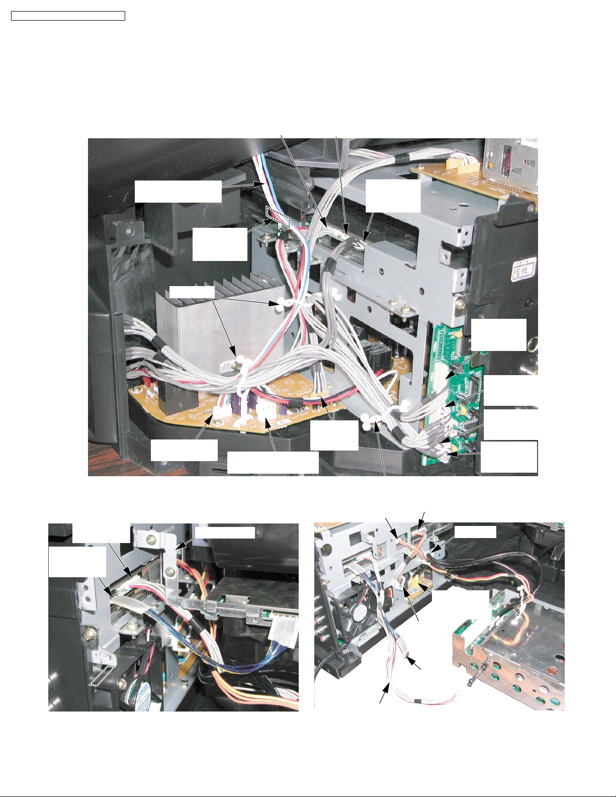
PT-43LC14 / PT-50LC14 / PT-60LC14
After servicing, make sure that all wires, leads, and clampers are placed in their original position. It is important for the best
operation of the unit.
Note: Use extreme care especially for the following.
P3402
(From LCD
Drive C.B.A.)
P5302
(From LCD
Drive C.B.A.)
Speaker Connector
Leads
P6004
(From Tuner
C.B.A.)
Clampers
P4503
(From Speaker)
GND Plate A
P6305
(From Operation C.B.A.)
P4501
(From Power C.B.A.)
No connection
P5501
(From Front
Jack C.B.A.)
P4505
(To Tuner
C.B.A.)
Clamper
P6002
(From Ballast C.B.A.)
P3501
(From Tuner
C.B.A.)
P3502
(From Front
Jack C.B.A.)
P3504
(From Front
Jack C.B.A.)
P3603
(From Audio
Amp C.B.A.)
P3401
(From Power C.B.A.)
Clamper
Fig. 9-3
16
P805
(From Ballast
C.B.A.)
Clamper
20-pin Cable
Connector Cable
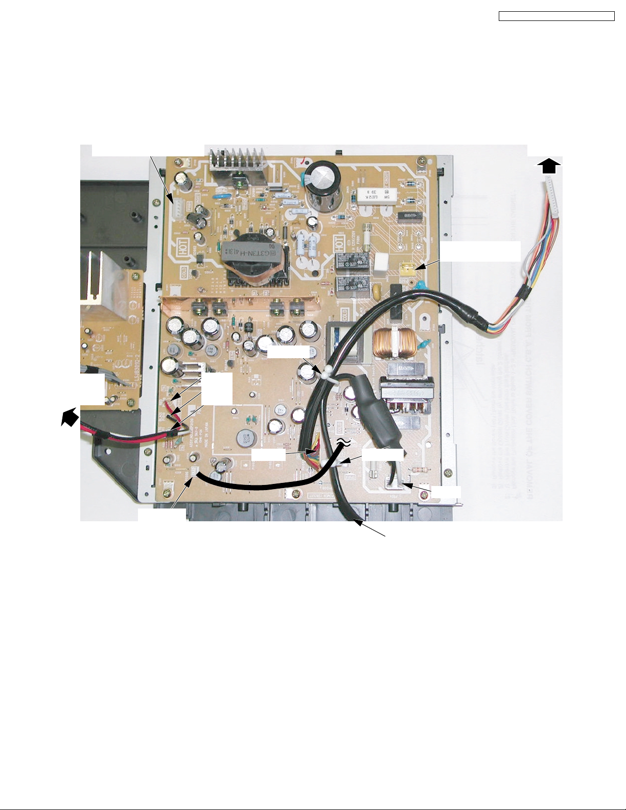
PT-43LC14 / PT-50LC14 / PT-60LC14
After servicing, make sure that all wires, leads, and clampers are placed in their original position. It is important for the best
operation of the unit.
Note: Use extreme care especially for the following.
P3401
P1001 (To Ballast C.B.A.)
(To Main
C.B.A.)
P805
(To Ballast C.B.A.)
P4501
(To Audio
Amp C.B.A.)
P1006
(To Fan 4)
P1009
P1010
P1011
Clamper
P1007
Clamper
P804
AC Cord
Fig. 9-4
17
PT-43LC14 / PT-50LC14 / PT-60LC14
5 DISASSEMBLY / ASSEMBLY PROCEDURES
5.1. CABINET SECTION
CABINET SECTION
DISASSEMBLY METHOD OF CABINET SECTION
Cabinet section contains following removal procedures:
REMOVAL OF THE BALLAST C.B.A. AND THE TV/TUNER UNIT FROM THE CABINET
REMOVAL OF THE PROJECTION UNIT FROM THE CABINET
REMOVAL OF THE TUNER C.B.A., THE MAIN C.B.A., THE REAR JACK C.B.A., THE AUDIO AMP C.B.A., THE POWER C.B.A. FROM
THE TV/TUNER UNIT
REMOVAL OF THE SCREEN UNIT AND THE SPEAKER FROM THE DISPLAY
REMOVAL OF THE MIRROR FROM THE BACK COVER
REMOVAL OF THE FRONT JACK C.B.A. AND THE OPERATION C.B.A. FROM THE CABINET
REMOVAL OF THE COVER SWITCH C.B.A. FROM THE CABINET
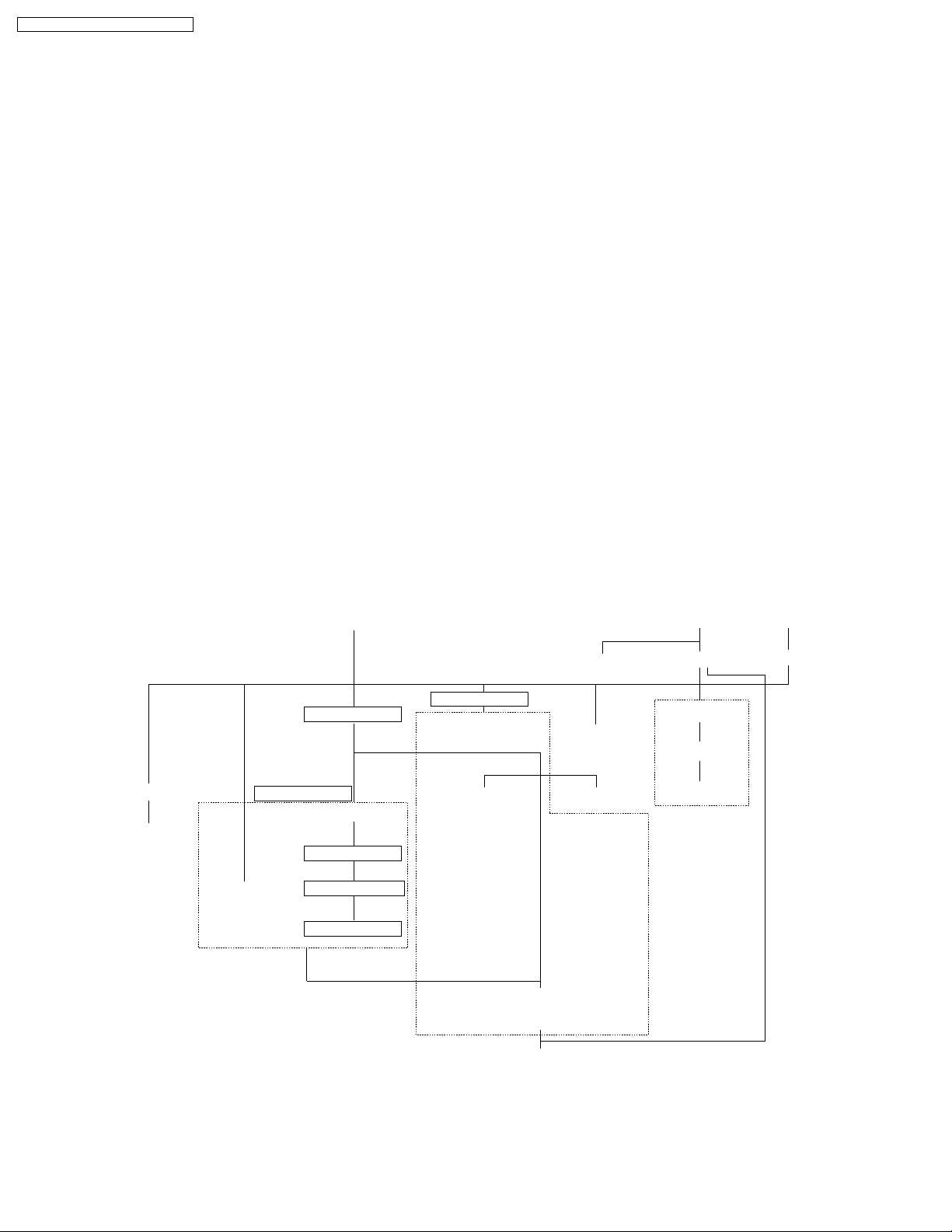
DISASSEMBLY FLOWCHART
This flow chart indicates the disassembly steps of the cabinet parts and the P.C.Boards in order to gain access to item (s) to be
serviced. When reassembling, perform the step (s) in the reverse order. Bend, route and dress the wires as they were originally.
OPERATION C.B.A.
FRONT JACK C.B.A.
REAR COVER
BALLAST C.B.A.
TV/TUNER UNIT
TUNER C.B.A.
MAIN C.B.A.
REAR JACK C.B.A.AUDIO AMP C.B.A.
POWER C.B.A.
PROJECTION UNIT
THERMISTOR 2 C.B.A.
THERMAL FUSE UNIT TOP DUCT 3 UNIT
THERMISTOR 1 C.B.A.
(LCD/PRISM UNIT, LIGHT IN POLARIZER, ETC)
FAN 3 UNIT
FRONT COVER UNIT
OPTICAL COVERLAMP COVER NETWORK C.B.A.
SCREEN UNIT
MIRROR
BACK PANEL
(DISPLAY)
SPEAKER
COVER SWITCH C.B.A.
Note :
a. Place a cloth or some other soft material under the P.C. Boards or Unit to prevent damage.
b. When reinstalling, ensure that the connectors are connected firmly and electrical components have not been damaged.
c. Do not supply power to the unit during disassembly and reassembly.
18
PT-43LC14 / PT-50LC14 / PT-60LC14
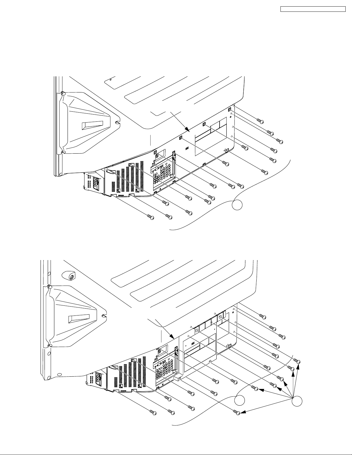
REMOVAL OF THE BALLAST C.B.A. AND THE TV/TUNER UNIT FROM THE CABINET
1. (PT-43LC14/PT-50LC14)
Remove the Rear Cover by removing the 18 Screws (401).
Rear Cover
Fig. D1-1-1
1. (PT-60LC14)
Remove the Rear Cover by removing the 20 Screws (401, 464).
Rear Cover
401
Fig. D1-1-2
19
401
464
PT-43LC14 / PT-50LC14 / PT-60LC14
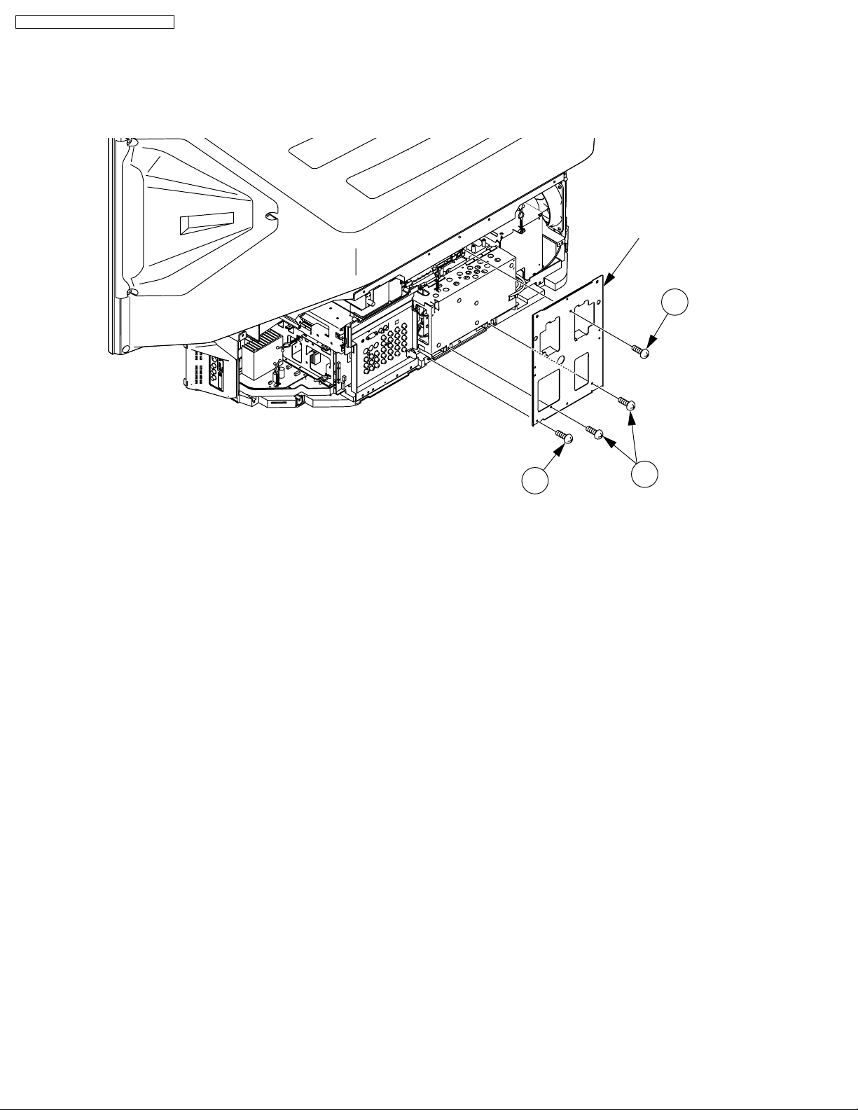
2. Remove the Rear Support Plate by removing the 4 Screws (401, 452).
Rear Support
Plate
401
Fig. D1-2
401
452
20
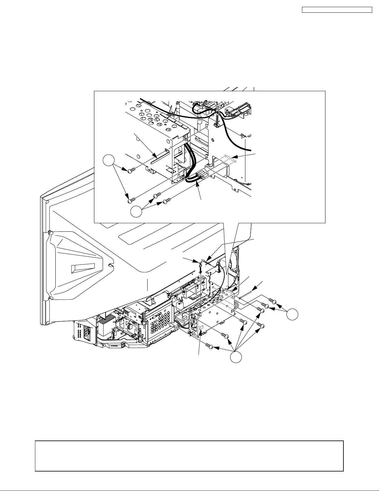
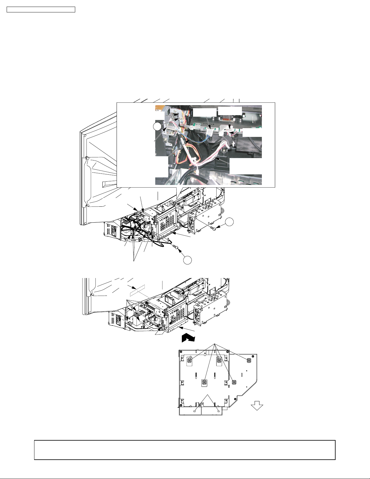
3. 1) Remove the 5 Screws (402) and remove Clamper-1.
2) Remove the 2 Screws (451) on the Lamp Socket.
3) Disconnect the Lamp Connector.
4) Avoiding the Ballast C.B.A., disconnect Connector P1306 (Thermal Fuse Unit) inside of the Ballast C.B.A.
5) Remove the Clamper from the Ballast C.B.A.
Clamper-1
PT-43LC14 / PT-50LC14 / PT-60LC14
402
451
Clamper
Lamp Socket
Lamp Connector
Note:
Do not remove the
Thermal Fuse Unit.
Ballast C.B.A.
Clamper-1
451
P1306
Fig. D1-3
Replacement Note of Ballast C.B.A.:
These parts will be necessary when replacing the Ballast C.B.A. Set aside, and keep and re-use.
• The Clamper on Ballast C.B.A.
• The Thermal Fuse Unit
21
402
PT-43LC14 / PT-50LC14 / PT-60LC14
4. 1) Disconnect Connector P2901 (Connector Cable) and release them from the clamper.
2) Disconnect Connector P2501 (20-pin Cable) and release it from the clamper.
CAUTION: Take extreme care not to damage the 20-pin Cable when disconnecting.
5. 1) Disconnect Connectors P3502, P3504, P5501, P4503, P6305 and release them from the clampers.
2) Remove the Screw (452) on the GND Plate A.
3) Remove the Screw (401) on the TV/Tuner Ass’y.
4) Lift up and slide the TV/Tuner Ass’y by releasing the 7 Guide Tabs.
CAUTION: Do not slide the TV/Tuner Unit before removing the 20-pin Cable.
GND Plate A
P5302
CAUTION:
20-pin Cable
P5501
P6305
P4503
P3502
Clampers
Slot
452
P3504
P2501
TV/Tuner Ass'y
401
Fig. D1-4
P2901
Clamper
Connector
Cable
452
holes
holes
<Bottom View of TV/Tuner Ass'y>
Fig. D1-5
Replacement Note of TV/Tuner Unit:
These parts will be necessary when replacing the TV/Tuner Unit. Set aside, and keep and re-use.
• 20-pin Cable
TV/Tuner Ass'y
Guide Tabs (X5)
Guide Tabs (X2)
Rear
22
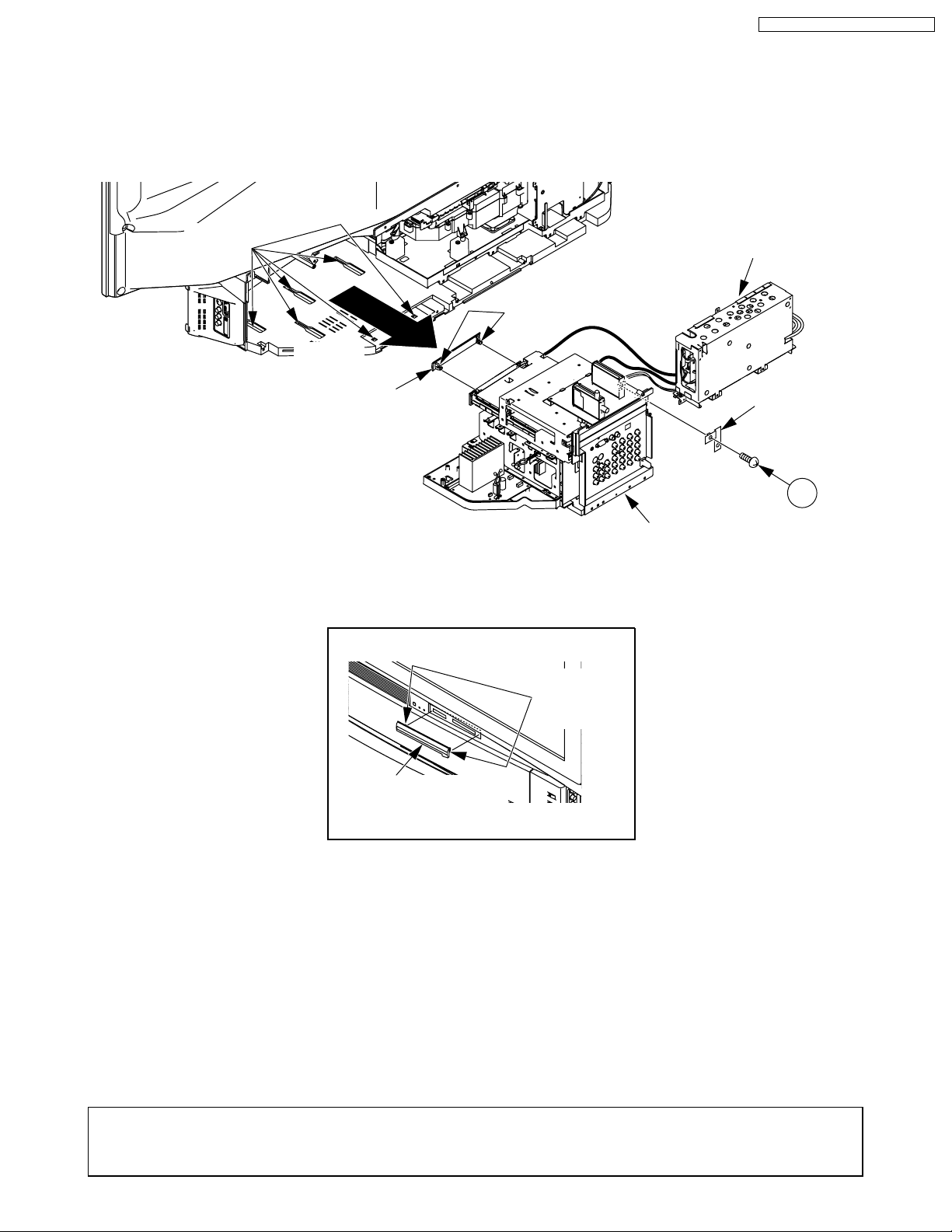
6. 1) Pull off the TV/Tuner Ass’y with the Ballast C.B.A. while taking care with the cables.
2) Remove the GND Plate A from the TV/Tuner Unit by removing the Screw (452).
3) Remove the SD Door Unit from the TV/Tuner Unit by releasing the 2 Locking Tabs.
holes
Locking Tabs
Slide
PT-43LC14 / PT-50LC14 / PT-60LC14
Ballast
C.B.A.
SD Door Unit
GND
Plate A
452
TV/Tuner Unit
Fig. D1-7-1
Reassembly Note: When installing the SD Door Unit, install the SD Door Unit with the 2 Locking Tabs from the front of the cabinet
after installing the TV/Tuner Unit into the cabinet.
Reassembly Note:
Locking
Tabs
SD Door Unit
<Front View>
Fig. D1-7-2
Replacement Note of TV/Tuner Unit:
These parts will be necessary when replacing the TV/Tuner Unit. Set aside, and keep and re-use.
• The GND Plate A
• The SD Door Unit
23
PT-43LC14 / PT-50LC14 / PT-60LC14
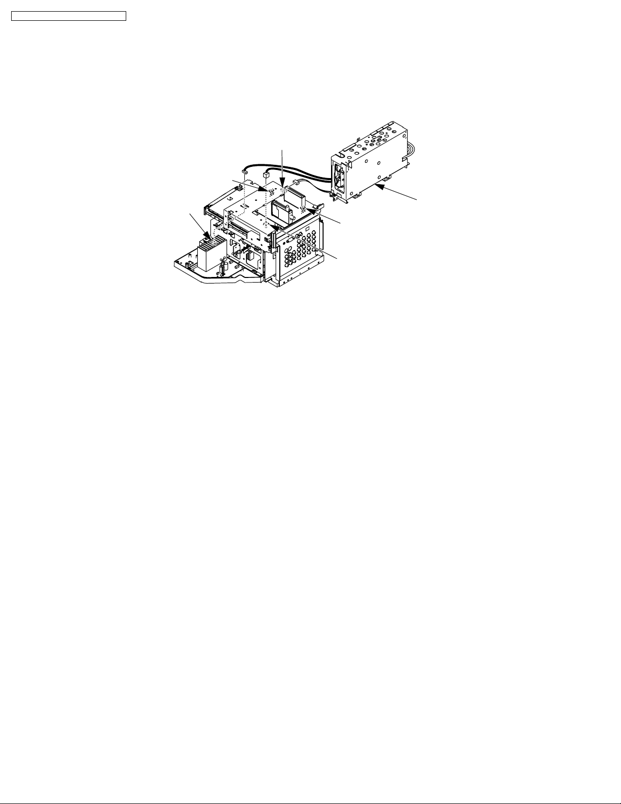
7. 1) Disconnect Connectors P6002, P805, P1001 and release them from the clampers.
2) Then, remove the Ballast C.B.A.
P6002
Clamper
P1001
Ballast C.B.A.
Clamper
P805
Fig. D1-8
24
PT-43LC14 / PT-50LC14 / PT-60LC14
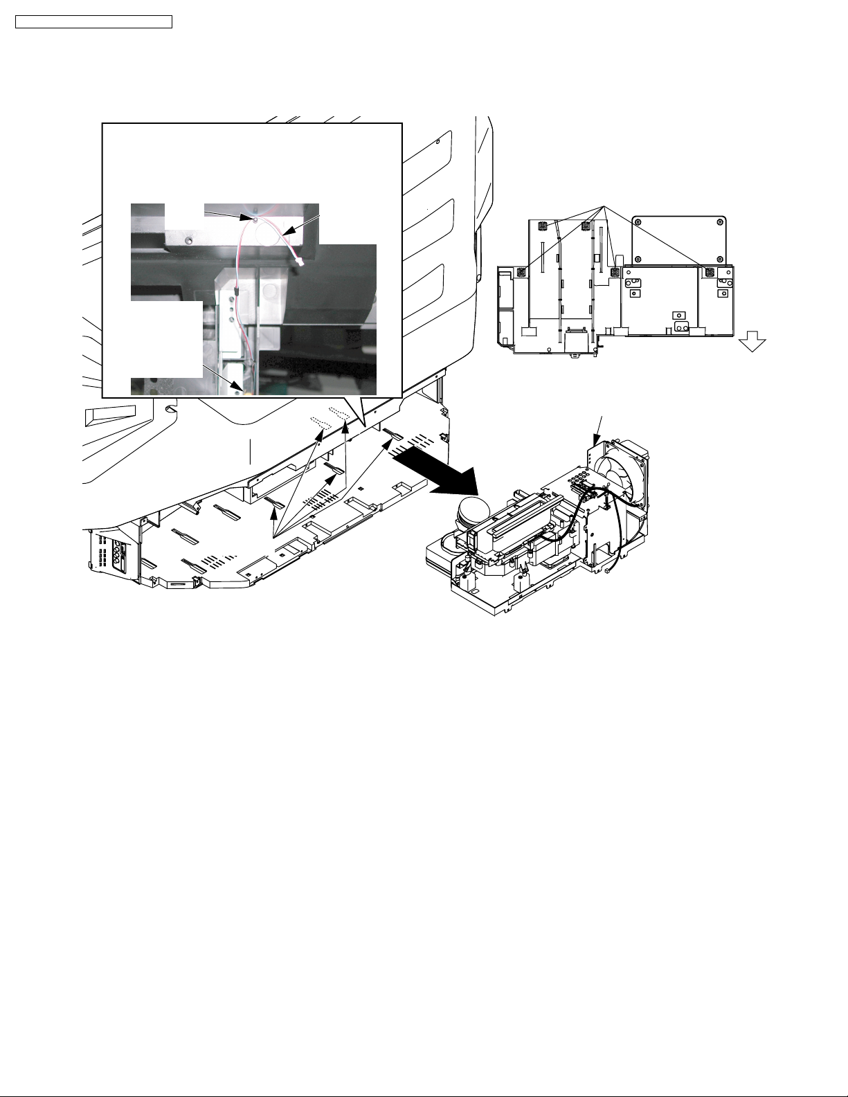
REMOVAL OF THE PROJECTION UNIT FROM THE CABINET
1. Remove the Ballast C.B.A. and the TV/Tuner Unit. Refer to Steps 1~6 in "REMOVAL OF THE BALLAST C.B.A. AND THE TV/
TUNER UNIT FROM THE CABINET."
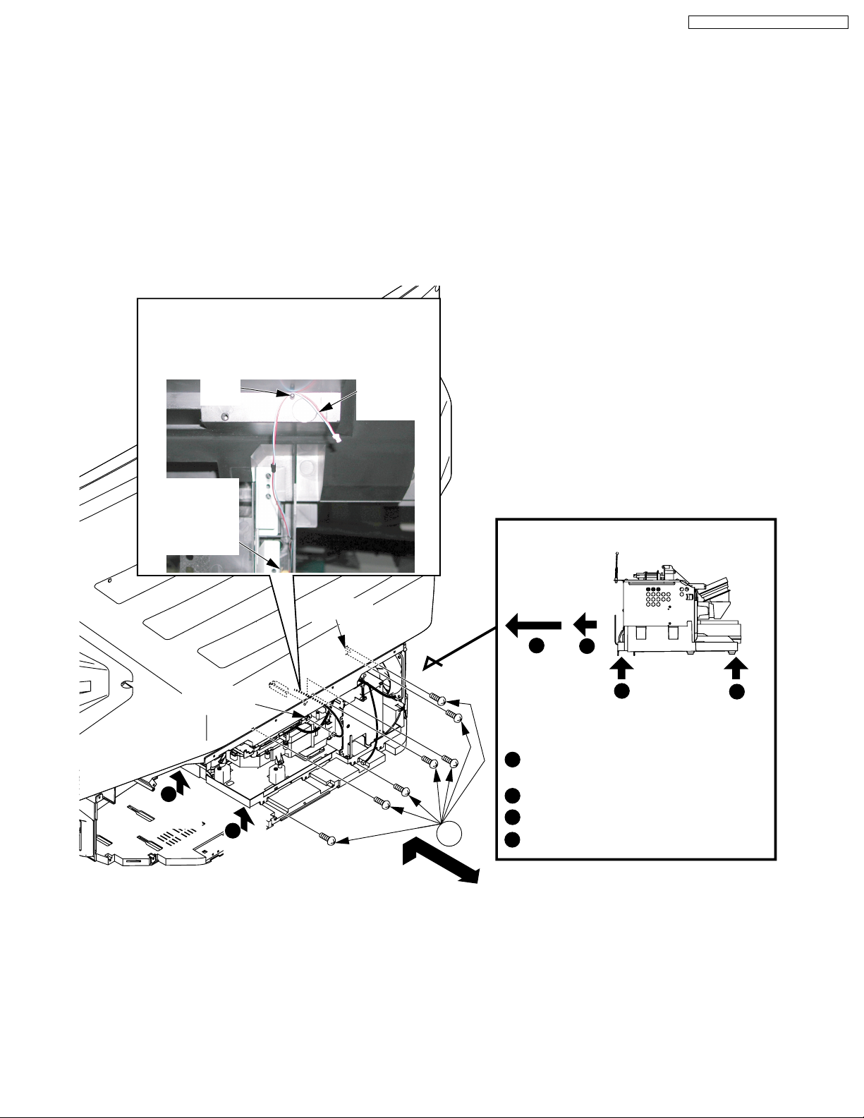
2. 1) Disconnect Connector P2502. Then, hook the P2502 cable to the pin.
2) Remove the 7 Screws (401) on the Projection Unit.
3) Lift up and slide the Projection Unit by releasing the 5 Guide Tabs.
Tips on removal of the Projection Unit:
First, slide the Projection Unit to the rear (approx. 1.5 inch (4 cm)). Then, lift up the front and the rear portions of the Projection
Unit by both hand to release the Guide Tabs. Then, slide out the Projection Unit.
Or, remove the Fan 3 Unit from the Projection Unit at first. Refer to Fig. D2-3.
CAUTION:
Disconnect Connector P2502
and hook it as follows.
P2502
Pin
Cable
Cover
Switch
C.B.A.
P2502
2
Up
3
Up
Boss
401
Fig. D2-1
Tips on removal of the Projection Unit
Slide
4
1
3
2
Up Up
<Side View>
1
Lift up and slide the Projection Unit
by approx. 1.5 inch (4 cm).
2
Lift up the front portion.
3
Lift up the rear portion.
4
Slide out the Projection Unit.
25
PT-43LC14 / PT-50LC14 / PT-60LC14
CAUTION:
Disconnect Connector P2502
and hook it as follows.
Cover
Switch
C.B.A.
Pin
P2502
Cable
Guide Tabs (X5)
<Bottom View of Projection Unit>
Projection Unit
Rear
Slide
holes
Reassembly Note:
Before installing the Projection Unit, confirm that the P2502 cable is hooked to the pin. Then, install the Projection Unit to the
cabinet.
Fig. D2-2
26
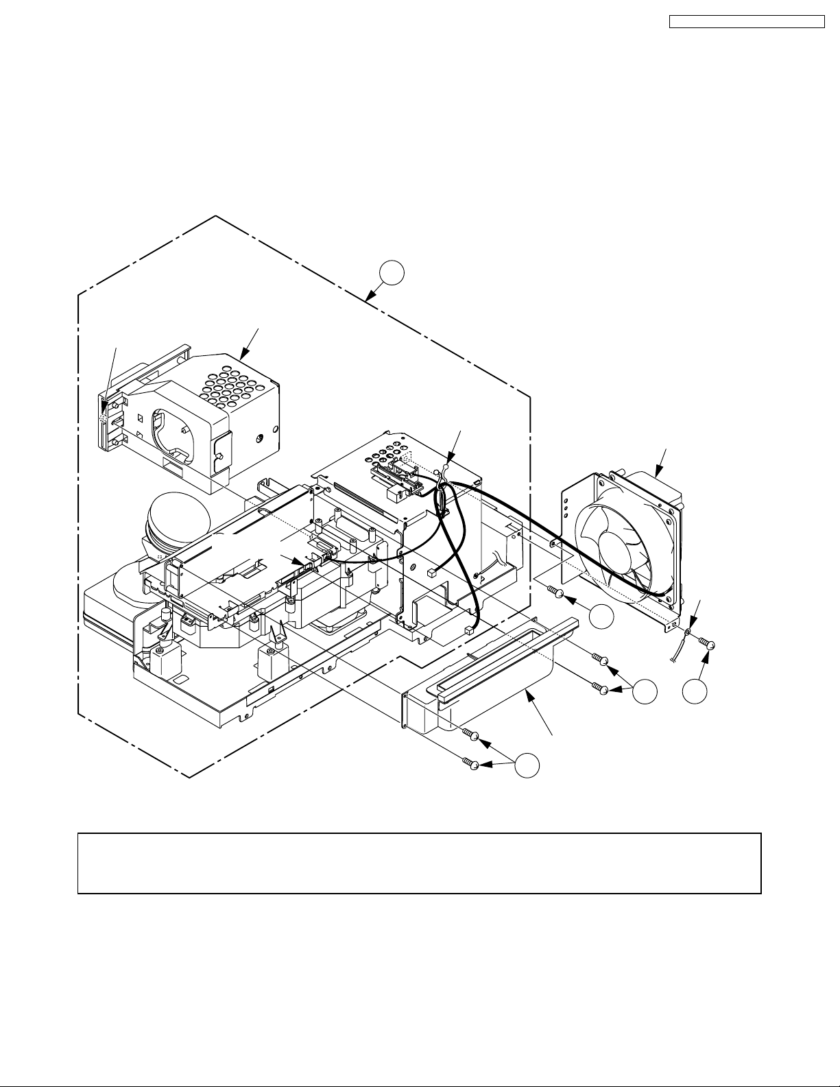
PT-43LC14 / PT-50LC14 / PT-60LC14
3. 1) Disconnect Connector P2904, and remove the Fan 3 Unit by removing the 2 Screw (402).
2) Remove the Top Duct 3 Unit by removing the 4 Screws (421).
CAUTION:
When removing the Screws (421) on the Top Duct 3 Unit, plastic dust may be produced. Therefore, confirm that there is no dust
on the Top Duct 3 Unit. If there is dust, clean the Top Duct 3 Unit with a brush, etc. Otherwise, dust may adhere to the inside of
the screen.
3) Remove the Lamp from the Projection Unit by loosening the Screw.
21
Projection Unit
Screw
for lamp
Lamp
P2904
Clamper
Fan 3 Unit
402
421
GND
Wire
402
Top Duct 3 Unit
421
Fig. D2-3
Replacement Note of Projection Unit (Ref. No. 21):
These parts will be necessary when replacing the Projection Unit (Ref.No. 21). Set aside, and keep and re-use.
• Fan 3 Unit
• Top Duct 3 Unit
27
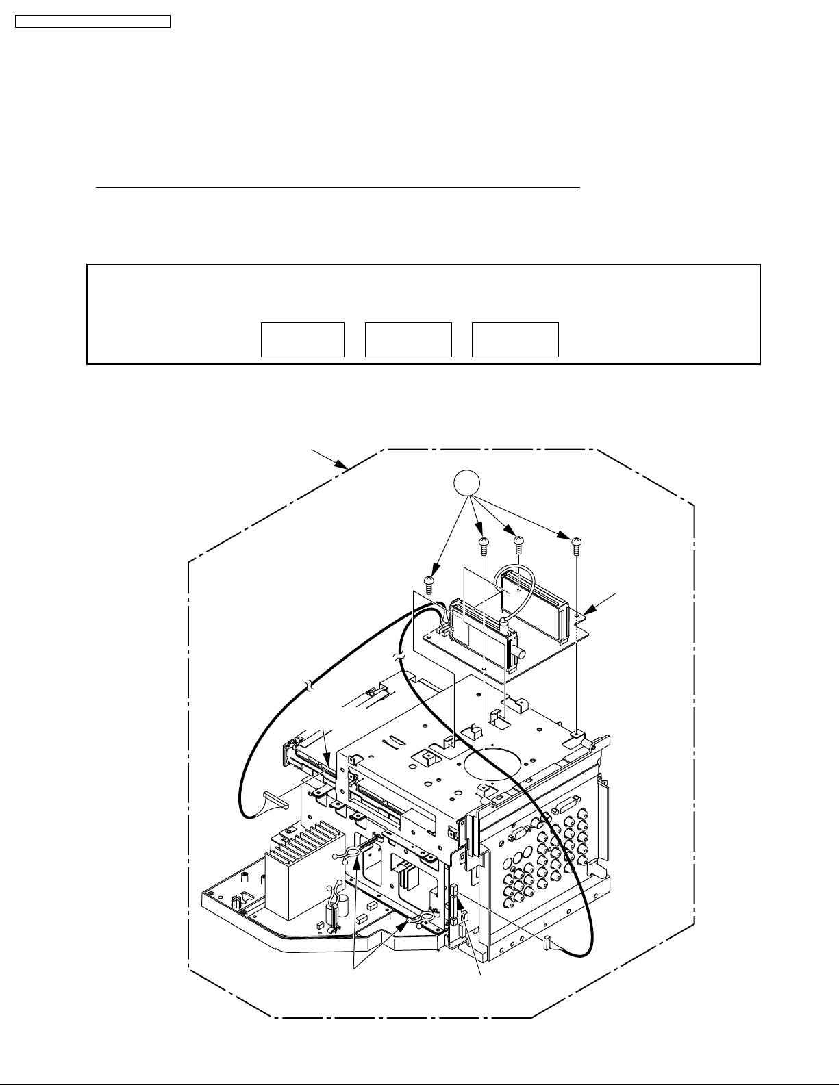
PT-43LC14 / PT-50LC14 / PT-60LC14
REMOVAL OF THE TUNER C.B.A., THE MAIN C.B.A., THE REAR JACK C.B.A., THE
AUDIO AMP C.B.A., THE POWER C.B.A. FROM THE TV/TUNER UNIT
CAUTION:
Be sure to make a note of the CURRENT LAMP value (value A) in Service Mode (1/3):
1.
LAMP OPERATION TIME is stored in EEPROM on the Main C.B.A. Therefore, before removing the Main C.B.A. or the TV/Tuner
Unit at the user’s location, make a note of the CURRENT LAMP value (value A) in Service Mode (1/3).
Then, after installing the new Main C.B.A. or the TV/Tuner Unit at the user’s location, set the CURRENT LAMP value to the original
value (value A) in Service Mode.
Otherwise, OSD and LED Lamp replacement indications will be displayed at the wrong time.
Note:
In case it is impossible to make a note of the CURRENT LAMP value because of a defective Main C.B.A., ask the customer
their daily average use and the approximate age of the current Lamp. Then, calculate the CURRENT LAMP value as follows
and make a note.
1. Remove the TV/Tuner Unit and the Ballast C.B.A. Refer to Steps 1~7 in "REMOVAL OF THE BALLAST C.B.A. AND THE TV/
TUNER UNIT FROM THE CABINET."
2. 1) Disconnect Connectors P6004, P3501 and release from the clampers.
2) Remove the Tuner C.B.A. by removing the 4 Screws (402).
Daily average use
(hours) (days) (hours)
Approx. age CURRENT LAMP
X=
TV/Tuner Unit
P6004
402
Tuner
C.B.A.
Clampers
Fig. D3-1
P3501
28
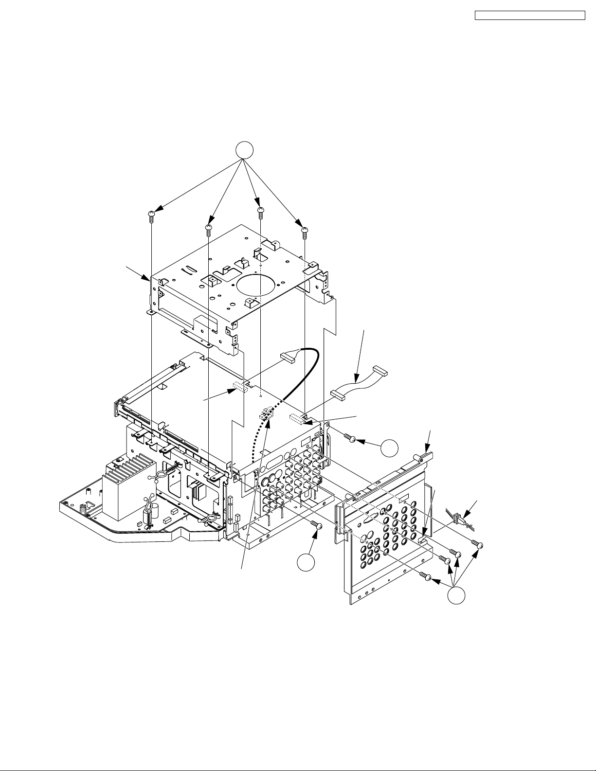
Rear Jack
Holder
P3402
Slot
AC Cord
Tuner
P.C.B.
Frame
Clamper
402
402
402
Connector Cable
P3401
402
3. 1) Disconnect Connector P3401 and release from the clamper.
2) Disconnect Connector P3402 and remove the Connector Cable.
3) Remove the Tuner P.C.B. Frame by removing the 6 Screws (402).
4) Release the AC Cord from the slot of the Rear Jack Holder.
5) Remove the Rear Jack Holder by removing the 4 Screws (402).
PT-43LC14 / PT-50LC14 / PT-60LC14
Fig. D3-2
29
PT-43LC14 / PT-50LC14 / PT-60LC14
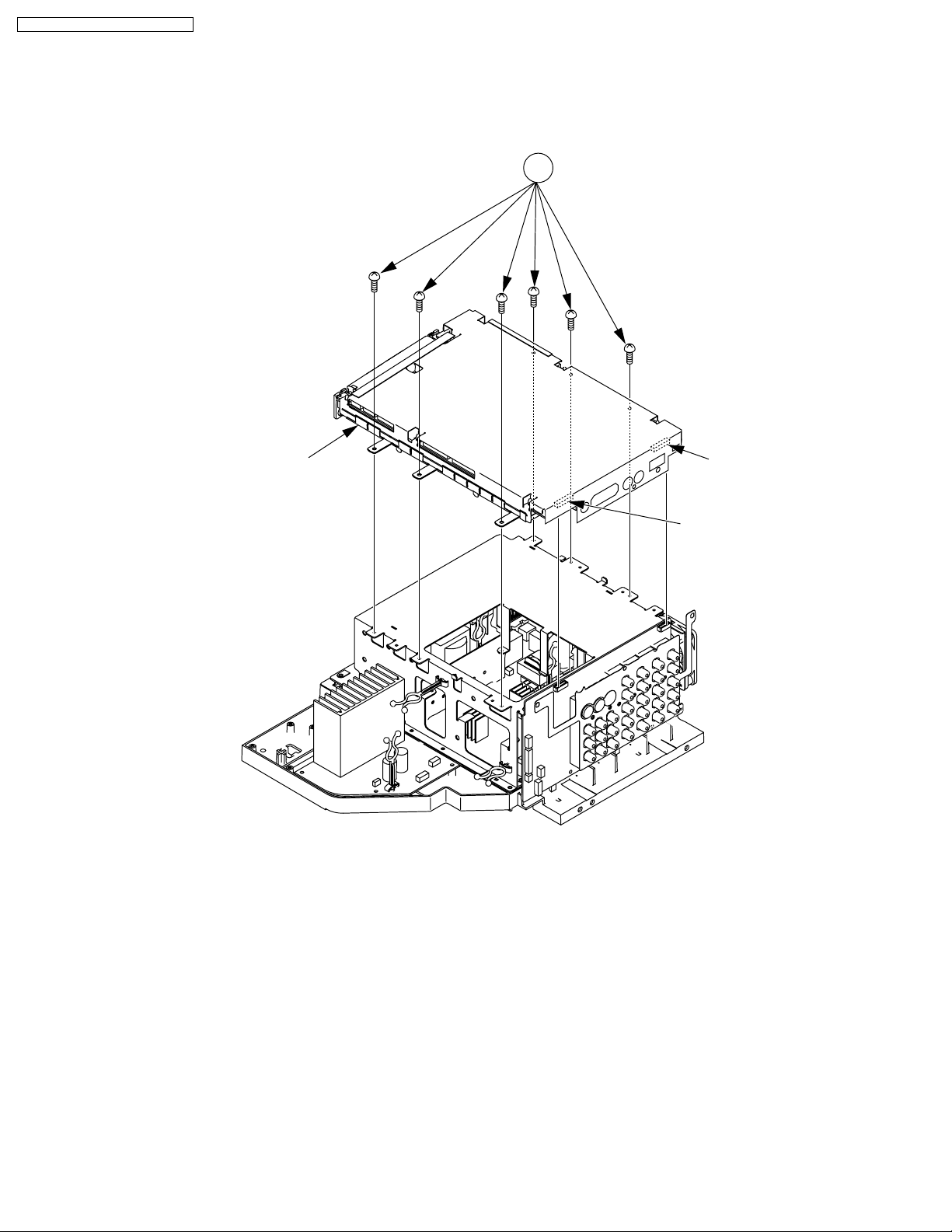
4. Remove the Main C.B.A. by removing the 6 Screws (402) and disconnecting Connector P3403 and P3404.
402
Main C.B.A.
P3404
P3403
Fig. D3-3
30
 Loading...