

Panasonic PN260493N-TH, PN260493N-MY, PN260493N-ID, PN260493N-SG Installation Manual
Installation Guide
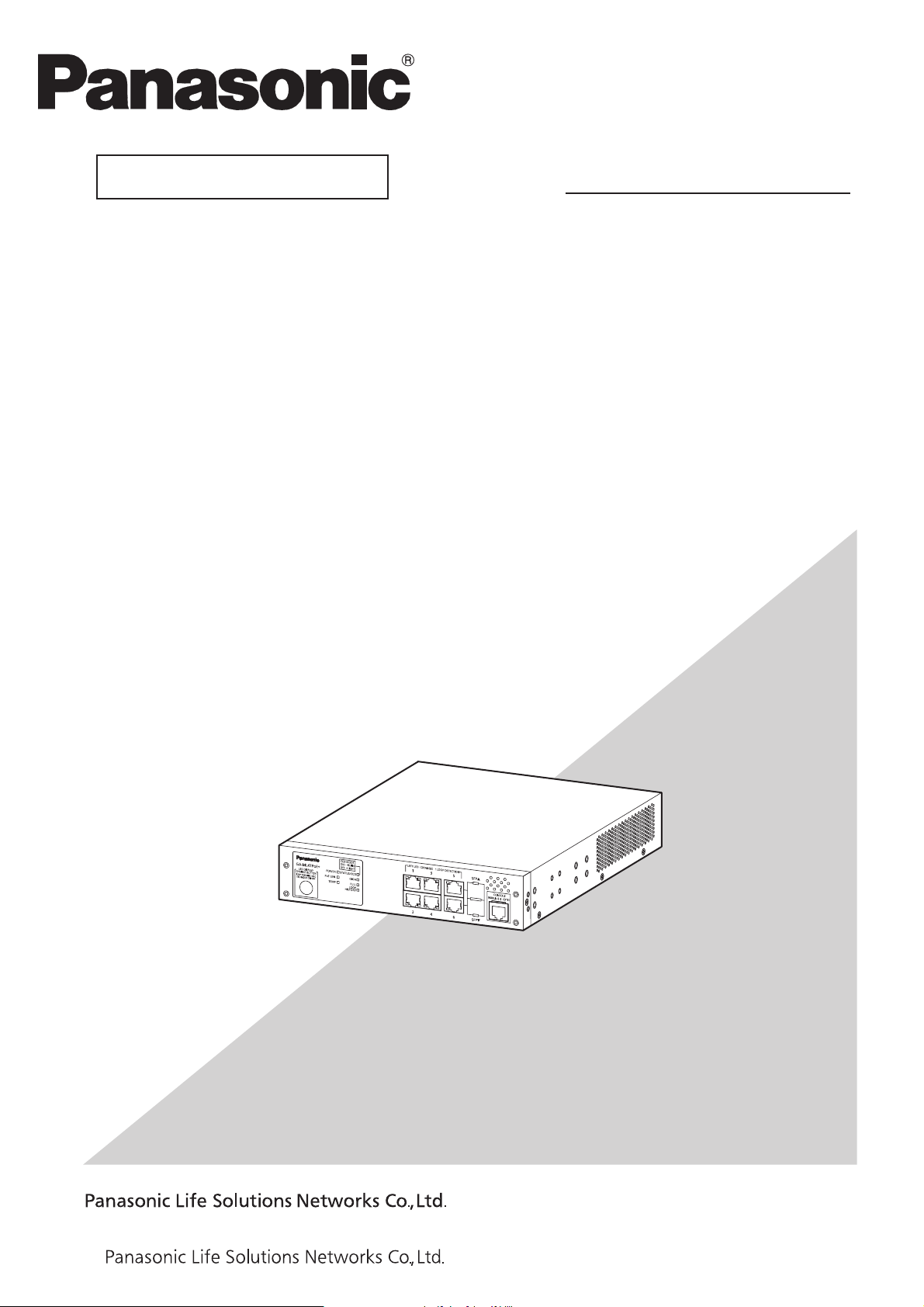
GA-ML4TPoE+
Model No.
PN260493N-TH
PN260493N-MY
PN260493N-ID
PN260493N-SG
Thank you for purchasing our product.
This document provides important information about safe and proper
operations of this Switching Hub.
Please read the "Important Safety Instructions" on pages from 3 to 6.
Any problems or damage resulting from disassembly of this Switching Hub
by customers are not covered by the warranty.
2-12-7, Higashi-Shimbashi, Minato-ku, Tokyo Japan, 105-0021
©
2019
I1019-0 Printed in Japan

Contents
Important Safety Instructions
Basic Instructions for the Use of This Product
1 Product Outline
1.1 Features
1.2 Specifications
1.3 Accessories
1.4 Basic operation
2 Part Names and Functions
2.1 LED display change
2.2 PoE power supply function
3 Installation and Configuration
3.1 Grounding Cable Connection
3.2 Mounting on a wall
3.3 Mounting to rack
3.4 Configuration of IP address (Basic)
3
7
8
8
9
11
11
12
15
17
18
18
19
20
21
Troubleshooting
23
2
Important Safety Instructions
This chapter contains important safety instructions for preventing bodily
injury and/or property damage. You are required to follow them.
Severity of bodily injury and/or property damage, which could result from incorrect
use of the Switching Hub, are explained below.
This symbol indicates a potential hazard
WARNING
that could result in serious injury or death.
This symbol indicates safety instructions.
CAUTION
The following symbols are used to classify and describe the type of instructions to
be observed.
This symbol is used to alert
users to what they must not do.
Deviation from these instructions could lead
to bodily injury and/or property damage.
This symbol is used to alert
users to what they must do.
WARNING
Do not use power supply other than AC 100 - 240 V.
Deviation could lead to fire, electric shock, and/or equipment failure.
Do not handle this Switching Hub and connection cables during a
thunderstorm.
Deviation could lead to electric shock.
Do not disassemble and/or modify this Switching Hub.
Deviation could lead to fire, electric shock, and/or equipment failure.
Do not damage the power cord. Do not bend too tightly, stretch, twist, bundle
with other cord, pinch, put under a heavy object and/or heat it.
Damaged power cord could lead to fire, short, and/or electric shock.
Do not unplug nor plug in the power plug with wet hands.
Deviation could lead to electrical shock, and/or equipment failure.
Do not insert, nor drop foreign objects such as metal or combustible things into
the inside through the openings, twisted pair ports, console port and SFP
extension slot.
Deviation could lead to fire, electric shock, and/or equipment failure.
Do not store or use the Switching Hub in places where it might get splashed
with liquids such as water, in places with a lot of humidity, in places with
conductive dust, or in places where there are corrosive and combustible gases.
Deviation could lead to fire, electrical shock, and/or equipment failure.
Do not store or use the Switching Hub in places where it will be exposed to
direct sunlight or high temperatures.
The temperature inside will rise, which may cause fire.
Do not store or use the Switching Hub in places where there are lots of
vibrations and impacts, or in unstable areas.
It might fall, which may cause injuries and/or equipment failure.
3
WARNING
Do not put the Switching Hub into fire.
Deviation could lead to explosion and/or fire.
Do not connect the console ports with any other console cables except for our
optional PN72001 RJ45-DSub 9-pin console cable.
Deviation could lead to fire, electrical shock, and/or equipment failure.
Do not use the Switching Hub in dusty environments such as on floors,
underneath floors, the backside of ceilings, or wiring panels.
Do not use the Switching Hub in very dusty areas such as on floors, underneath
floors, the backside of ceilings, or wiring panels. Deviation could lead to fire,
electrical shock, and/or equipment failure. It is recommended that the Switching
Hub be operated in environments such as the inside of racks where it is difficult for
dust to be generated.
CAUTION
Use the bundled power cord (AC 100 – 240 V specifications).
Deviation could lead to electric shock, malfunction, and/or equipment failure.
Unplug the power cord in case of equipment failure.
Deviation, such as keeping connected for a long time, could lead to fire.
Be sure to connect the ground cable.
Otherwise this might cause electrical shocks, misoperations and malfunctions.
Connect the Switching Hub via the supplied power cord to the outlet which is
connected to the ground.
If the outlet is not connected to a ground, connect the ground cable to the ground
terminal screw.
Connect the power cord firmly to the power port.
Otherwise this might cause electrical shocks and malfunctions.
Unplug the power cord if the STATUS/ECO LED (Status/ECO mode) blinks in
orange (system fault).
Deviation, such as keeping connected for a long time, could lead to fire.
Handle the Switching Hub carefully so that fingers or hands may not be
damaged by twisted pair port, SFP extension slot, console port, or power cord
hook block.
When mounting the Switching Hub on a wall, mount it securely using wall
mount brackets to prevent the Switching Hub from falling due its weight and
that of the connection cables.
Deviation could lead to falling, injury and/or equipment failure.
If the device is going to be mounted onto a rack, use the 2 installation brackets
(for 19-inch rack mounting) which include the 19-inch rack mounting brackets
(for 1 rack) and the 8 screws (for the rack installation brackets and for the main
unit connections), and install the installation brackets into each of the 4
horizontal holes in the device, then securely secure it and set it up.
If it is not firmly secured, then deviation could lead to falling, injury and/or
equipment failure.
4
CAUTION
Up to two Switching Hubs can be connected by using the connection brackets and
connection bracket screws. Attach the connection brackets to the connection
bracket screw holes on the front and back panels to securely fix the Switching
Hubs before installation.
If the Switching Hubs are not fixed securely, they may fall, leading to injury and/or
equipment failure.
Check whether the optical fiber cable connectors are contaminated with dust, etc.
This might cause the optical signal to not be transmitted normally, and cause
misoperations and malfunctions. If they are contaminated, make sure to cleanthem
off, then connect them to the optical fiber ports.
This Switching Hub is to be periodically serviced in order to maintain its
performance.
Please choose a product administrator, and have them be sure to implement
periodic maintenance. When doing maintenance, check the inspection chart that is
posted on our website which has the requisite items listed on it.
When using this Switching Hub to design systems, use it after applying
appropriate measures such as setting up redundant configurations.
Communications failures might be generated due to causes such as malfunctions or
misoperations while the Switching Hub is being used.
When using this Switching Hub for applications which require extremely high
reliability, be careful to expend all possible means to ensure safety and
reliability.
This Switching Hub was not designed nor manufactured with the intention that it be
used for applications (in use with railways, aviation, and medical care, etc. whereas
the influence rate due to communications failures is extremely high in regard to
systems that directly affect systems and human lives) which require extremely high
reliability.
Be aware of glitches which are caused in the usage environments such as
age-related degradation, etc.
This may vary depending upon conditions such as utilization rates and usage
environments, but performance might decrease due to the age-related degradation,
etc. of components. It is recommended that this Switching Hub be replaced about
five years after it has been installed.
Be careful in regards to environmental restrictions whereby the Switching Hub
can be used.
Please isolate the business power lines and communications lines. Isolate
distribution lines and other distribution lines, and low current power lines, optical
fiber cables, metallic water conduits, and gas conduits, etc. Noise may be generated
in the communications lines which might cause communications glitches.
Do not connect any other devices except for
10BASE-T/100BASE-TX/1000BASE-T devices to the twisted pair ports.
Deviation could lead to equipment failure.
Do not insert any other modules into the SFP expansion slots except for our
optional SFP modules (PN54022/PN54024).
Deviation could lead to equipment failure.
Check our website for the latest information on supported SFP modules.
Do not connect the console ports with any other device except for Serial
communication terminal.
Deviation could lead to equipment failure.
5
CAUTION
To connect a power receiving equipment supporting IEEE802.3at to this
Switching Hub, use a cable rated Cat5e or higher.
Using other cables may result in heat generation, ignition, and/or equipment failure.
Important Requests on Protection from Lightning Strike
It is strongly recommended that a lightning arrester (SPD) be installed on the
twisted pair port side and the power supply side of this Switching Hub.
Malfunctions might be caused due to overcurrent and overvoltage due to the
effects of lightning strikes.
If you connect a network camera, a wireless access point, or other devices that can be
affected by a lightning strike (in particular, devices installed outdoors) to the twisted pair
port of this Switching Hub, a lightning surge current/voltage may be conducted to this
Switching Hub through the twisted pair cable, leading to malfunction. If you connect such a
device, it is strongly recommended that you install a surge protective device (SPD) on the
twisted pair port side of this Switching Hub.
A lightning surge current/voltage may be conducted to this Switching Hub through the
power supply or ground wire connected to the power port, leading to malfunction. If a
lightning surge current/voltage may flow in through the power supply or ground wire, it is
recommended that you install a surge protective device (SPD) on the power port side of this
Switching Hub.
6

Basic Instructions for the Use of This Product
For inspection and/or repair, consult the retailer.
Use commercial power supply from a wall socket, which is close and easily accessible to this
Switching Hub.
Unplug the power cord when installing or moving this Switching Hub.
Unplug the power cord when cleaning this Switching Hub.
Use this Switching Hub within the specifications. Deviation could lead to malfunction.
Do not touch the twisted pair cable modular metal terminals which are connected to RJ45
connectors (twisted pair ports) or the connectors, nor place them near electrically-charged
objects. Static electricity could lead to equipment failure.
Do not put the modular plug of the connected twisted pair cable on objects that can carry
static charge, such as carpet. Do not place it in the proximity. Static electricity could lead to
equipment failure.
Do not put a strong shock, including dropping, to this Switching Hub. Deviation could lead to
equipment failure.
Before connecting a console cable to the console port, discharge static electricity, for example
by touching metal appliance (do not discharge by touching this Switching Hub).
Please use this Switching Hub in place where ambient temperature is from 0 to 50°C and, do
not store and/or use this Switching Hub in the environment with the characteristics listed
below.
(Store and/or use this Switching Hub in the environment in accordance with the
specification.)
- High humidity. Possible spilled liquid (water).
- Dusty. Possible static charge (such as carpet).
- Under direct sunlight.
- Possible condensation. High/low temperature exceeding the specifications environment.
- Strong vibration and/or strong shock.
Failure to satisfy the conditions above may result in a fire, electric shock, equipment failure,
and/or malfunction. Such events are not covered by the warranty.
*If it is used beyond the operating environmental temperatures, then the protective devices
will start working and the Switching Hub power will be shut off.
Do not block the ventilator of the Switching Hub.
Blocked ventilator induces the heat accumulation inside, causing equipment failure and/or
malfunction.
If used at a temperature out of the operating temperature range, deviation could lead to
malfunction.
Operation is not guaranteed if a module other than the optional SFP extension modules
(PN54022/PN54024) is inserted into the SFP extension slot.
For the latest information about compatible SFP extension modules, check our website.
When using two Switching Hubs, do not stack them. When you place them side by side, allow
for a space of 20 mm or more between them. This space is not necessary if you use supplied
connection brackets.
When Switching Hubs mounting to rack, leave a minimum of 20 mm space between them.
1. Please note that Panasonic shall not bear any liability whatsoever for any damages
(this shall include lost earnings, lost opportunities, etc. but this is not restricted to these
things) which were generated in relation to damages caused by operations and usage,
or the inability to use this Switching Hub, whereby the customer does not follow
this Installation Guide.
2. The contents described in this document may be changed without prior notice.
3. For any question, please contact the retailer where you purchased the product.
7

Product Outline
1
GA-ML4TPoE+ is an Ethernet Switching Hub with management function having 6ports of
10/100/1000BASE-T and SFP extension slot, one of which is selectable.
Ports 1 to 4 support IEEE802.3at/af PoE power supply function.
1.1 Features
Ports 1 to 4 are 10/100/1000BASE-T ports corresponding to auto negotiation.
Also their speed and communication mode can be switched by configuration.
Ports 5 and 6 can be used as a 10/100/1000BASE-T port corresponding to auto
negotiation or an SFP extension slot exclusively.
Ports 1 to 4 can supply power conforming with IEEE802.3at and 802.3af. Supplying
power up to 30 W per port, and up to 62 W in total is possible.
Is equipped with PoE auto reboot functions, and monitoring, and the switching of the
power supply OFF/ON to ports is possible via Ping, LLDP, and the 3 traffic volume methods.
Fanless design solves noise problem or fan failure.
All twisted pair ports support straight/cross cable auto sensing function. Simply
connect devices with straight cables, whether it is a terminal or a network device.
(This function does not work if the port communication configuration is set at Fixed
or Link Aggregation. Ports 1 to 4 are set at MDI-X. (default))
Telnet/SSH allows remote configuration changes and verifications of the Switching Hub.
Remotely configure the PoE settings for each port (Ports 1 to 4).
The connection status for each port is detected by the power saving mode, and it can suppress
the power consumption to required volumes when not linked up. (Factory default: deactivated)
Rapid Spanning Tree Protocol is supported, allowing to build a system with redundancy.
The IEEE802.1p compatible QoS function is supported.
Supports triple authentication that can simultaneously wait on IEEE802.1X authentication,
MAC authentication, and WEB authentication via one port, and an authentication
network which is matched to the kinds of connection terminals can be constructed.
Equipped with step authentication functions, and can prevent illegal access of the terminals.
Since it is equipped with authentication supplicant functions, a more robust security
configuration can be configured in combination with the upper switch’s IEEE802.1X
authentication functions.
Due to the loop detection/shutoff function, a port where loop has occurred can be
automatically shut off to prevent loop failures. When a port is shut off and recovered
automatically, SNMP trap can be sent to notify the incident to the administrator.
Moreover, the port with a loop can be identified by loop notification on the LEDs on
the main unit and referring the history of loop on the setting screen.
The PoE scheduler function enables scheduling of PoE power supply control.
Supports ZEQUO assist Plus. Processes from introduction to maintenance can be
performed easily.
8
 Loading...