

Page 1

10
th
Generation Plasma Panel Replacement
This seminar covers 10
th
generation models
Panasonic Service and Technology Company
National Training
Page 2
Prepared by
Cesar Perdomo
Panasonic Service and Technology Company
National Training
Copyright © 2007 by Panasonic Service and Technology Company
All rights reserved. Unauthorized copying and distribution is a violation of law.
!
Warning
This service information is designed for experienced repair technicians only and is not designed for use by the
general public. It does not contain warnings or cautions to advise non-technical individuals of potential dangers
in attempting to service a product. Products powered by electricity should be serviced or repaired only by
experienced professional technicians. Any attempt to service or repair the product or products dealt with in this
service information by anyone else could result in serious injury or death.
Page 3

Summary
This seminar covers:
• Procedure to prepare the panel report form.
• Familiarization with symptoms exhibited by defective panels.
• Front cabinet removal procedure.
• Panel replacement procedure.
• Procedure to correct introduced problems after replacement.
• Adjustments procedure.
• Final inspection
Page # 1
Page 4
Topics
PDP Panel Replacement Report
Required Equipment
Proper Grounding Procedure
Front Cabinet Removal
H/DG Block Assembly Removal
Panel Cable Removal/Installation
Check-list After Panel Replacement
Colorimeter
White Window Pattern
Preparation for Adjustment
Presetting Brightness and Contrast
Setup
Driver Set-up Adjustment
White Balance Adjustment
Cleaning Procedure
Glossary
Page # 2
Page 5

Plasma Display Panel Replacement Report
Page # 3
Page 6
Blank Form Download Procedure (1)
Page # 4
Page 7
Blank Form Download Procedure (2)
Page # 5
Page 8
Blank Form Download Procedure (3)
Page # 6
Page 9

Blank Form Download Procedure (4)
Page # 7
Page 10
Blank Form Download Procedure (5)
Page # 8
Page 11

Required Equipment
Required Equipment:
• A stand - Part # TY-ST05K or Equivalent. Available from Panasonic's Parts
Department - Call 1- 800-833-9626
• An oscilloscope - Dual Trace - Delayed Sweep - 100MHz, or Better
• A DVM
• A digital camera
• Microsoft Excel 97 or later
• E-mail Service
• Hand Tools
•
Optional Test Equipment
• Digital TV Signal Generator - Sencore* VP403C or equivalent
• Colorimeter - Sencore* CP5000 or equivalent (Colorimeter measures the screen’s
color temperature).
Page # 9
Page 12

Follow proper grounding procedure
Warning:
Make sure to follow proper grounding procedure when involved in Plasma TV panel replacement.
Many electronic components used in this Plasma TV are very sensitive to Static Electricity.Further
damages can be caused to the set if these measures are not observed.
Electrically conductive wrist band, bench top mats, floor mats, toes/heels grounders, paint and floor
finishes are recommended as measures of prevention against electrostatic discharge.
Page # 10
Page 13

Front Cabinet Removal Only (TH-42PX75U)
Follow this procedure when only removing the “Front Cabinet”.
If the front cabinet needs to be removed for glass replacement or for any other reason, it’s not
necessary to disassemble the entire TV to do so. This can be done by only removing a few screws
and a few connectors. (For illustration, see the picture on the next slide)
1. Remove the screws securing the TV’s rear cover
2. Remove the rear cover
3. Disconnect the left and right speakers wires.
4. Disconnect connector A1 and A52 from the A board (Release cables from the clampers as
indicated on the picture of the next slide).
5. Remove 6 screws from the panel and 4 screws from the stand bracket.
Page # 11
Page 14

Front Cabinet Removal Only TH-42PX75U
Page # 12
Page 15
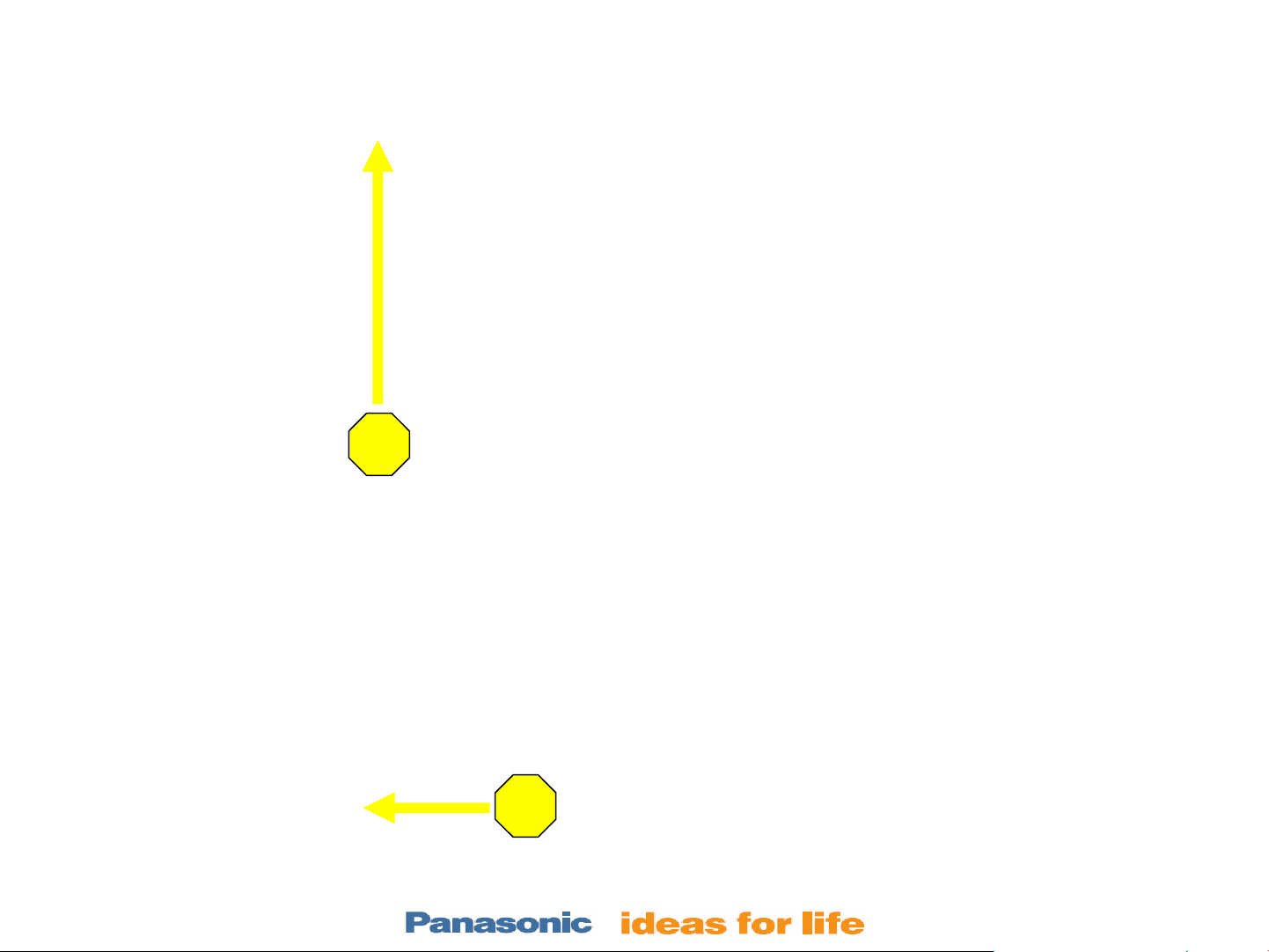
Front Cabinet Removal Only (TH-42PX75U)
To remove the front cabinet, tilt the bottom out and lift up slightly.
2
1
Page # 13
Page 16

Picture Of The Panel After Removing the Front Cabinet
Page # 14
Page 17

Front Cabinet Removal Only TH-42PZ700U
Follow this procedure when only removing the “Front Cabinet”.
If only the front cabinet needs to be disassembled, remove the metal bracket located on the front of
the H/DG board assembly and also remove the left and right speakers. (For illustration, see the
pictures on the next 2 slides)
1. Remove the TV’s rear cover
2. Remove 18 screws securing the metal bracket in front of the H and the DG board.
3. Remove the metal bracket.
4. Disconnect the left and right speakers wires.
5. Remove the L and R speakers. (Remove 1 screw as indicated on the picture of the next slide)
6. Disconnect connectors H11, H12, and H51 from the H board and connectors DG35 and DG52
from the DG board. (Release cables from the clampers as indicated on the picture of the next
slide).
7. Remove 11 screws from the panel and 2 screws from the stand bracket.
8. With the assistance of another person, hold the front cabinet and tilt the bottom out and lift up
slightly to remove the front cabinet. (See picture on the previous slide)
Page # 15
Page 18

Front Cabinet Removal Only (TH-42PZ700U)
Page # 16
Page 19

Front Cabinet Removal Only (TH-42PZ700U)
Page # 17
Page 20

(TH-42PZ700U)
9. Release the Left and Right side speaker cables from the 2 clampers on the panel
Page # 18
Page 21

Panel Removal
Page # 19
Page 22

H/DG Block Assembly Removal (TH-42PZ700U)
Follow this procedure
after removing the front
cabinet.
1. Remove connectors
from the H and the DG
board as indicated on
the picture.
2. Release cables from
clampers.
3. For models with a
metal bracket attached
to the top of the H/DG
block assembly,
remove the 3 screws
on the bracket and
remove it.
4. Remove the H/DG
block assembly.
Page # 20
Page 23

Panel’s Screws (TH-42PZ700U)
5. Transfer the D, P SS, SC, SU, SD, PB, AC socket, and all brackets from the defective panel to the
new panel.
Page # 21
Page 24

Panel Removal (TH-58PZ750U)
1. Remove the TV’s rear cover
2. Remove the screws securing the metal bracket in front of the H and the DG board.
3. Remove the metal bracket.
4. Disconnect the left and right speakers wires.
5. Remove the L and R speakers. (Remove 1 screw as indicated on figure 1)
6. Disconnect connectors from the H board and the DG board. (Release cables from the clampers)
7. Remove 14 screws from the panel and 2 screws from the stand bracket. (See picture on the next slide)
8. With the assistance of another person, hold the front cabinet and tilt the bottom out and lift up slightly to
remove the front cabinet. (See figure 2)
Figure 1
2
1
Figure 2
Page # 22
Page 25

Panel Removal (TH-58PZ750U)
6. Remove circled screws and transfer the D, P SS, SC, SU, SD, PB, AC socket, and all brackets
from the defective panel to the new panel.
Page # 23
Page 26

Panel Cable Removal/Installation
Cable Removal
To release the
cables, flip the
top to open.
Cable Installation
The Flex-cables from the panel should
be inserted straight into the connector.
When locking the connectors, make
sure the cables are seated properly.
This cable was not inserted properly
OK
NG
Page # 24
Page 27

Shipping Container
To remove the panel from the box:
• Cut the straps.
• Lift-up the top of the box.
• Remove the panel.
Page # 25
Page 28

Protective Plastic Frame
Note: The new Panel is shipped in a plastic frame. Do not remove the screws
holding the panel to the frame until the front cabinet is ready to be installed.
The PC boards from the old panel should be transferred to the new panel while
it’s still attached to the plastic frame.
Remove the screws from the plastic frame after the panel has been placed on
the stand and then proceed to remove the plastic frame.
Page # 26
Page 29
Check-List After Panel Replacement
1. Verify that the original complaint was corrected and no other problem was created.
2. Connect a video/audio signal and verify for proper operation.
3. Run the built-in patterns.
4. Make sure the screen is clean.
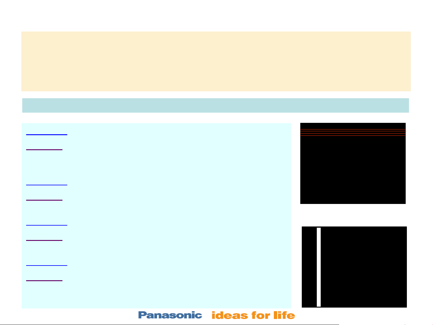
List of symptoms that may occur after panel replacement and solutions to correct them.
Symptom: The TV shuts down and the power LED blinks 6 times.
Solution:
sure that the ribbon cables between the D and C boards are properly
seated.
Symptom:
Solution:
panel flex-cables.
Symptom:
Solution:
SU/SD boards are seated properly.
Symptom:
Solution:
affected. Also check for possible defective C board on the new panel.
Check for missing cable between the C boards. Also make
The TV shuts down and the power LED blinks 8 times
Check for proper connection between the SS board and the
Horizontal fine line(s).
Make sure that the flex-cables between the panel and the
Vertical bar(s.)
Check connections on the C board that drives the section
Page # 27
Page 30

Adjustments
Page # 28
Page 31

Colorimeter (Analyzer)
A colorimeter is a tool that characterizes color samples to provide an objective measure of color
characteristics.
It is attached to the TV screen using suction cups to measures the light output of a display like a
Plasma TV to allow the adjustment of red, green and blue cutoff and drive controls for a 6500
degree color temperature.
It provides:
• Color-temperature readings in kelvins (K)
• Light-output readings in foot-lamberts (ftL)
• The temperature's precise points on the CIE chart.
Color temperature definition
Is a measurement of the color of light radiated by an object while it is being heated.
Colorimeter
Page # 29
Page 32

White window pattern
The White Window pattern is used together with a Colorimeter to measure the color of white or
gray that a Plasma TV produces. This is known as the TV's white balance. The interior window is
usually adjustable from 100 IRE (full white) to 0 IRE (full black) to allow the white balance to be
measured and/or adjusted at any desired luminance level. The black background level remains
fixed.
The pattern is often set to 70-80 IRE
and is set to 10-30 IRE
to adjust a set of low luminance white balance adjustments on a display.
to adjust a set of high luminance white balance adjustments
70-80 IRE
Drive controls
The three-color-controls used to balance
the bright end of the grayscale are
typically called drive controls.
10-30 IRE
Cutoff controls
The three-color-controls used to balance
the dark end of the grayscale are
typically called cutoff controls.
Page # 30
Page 33

Preparation for Adjustments
It is recommended that the Plasma panel goes through a burn-in period of roughly 200 hours before
performing white balance adjustment.
Turn on the TV at least 30 minutes before adjusting it (The black level and the grayscale on most
sets will drift during warm-up).
1. Preset the brightness and contrast controls.
The brightness and contrast should be adjusted under the same
lighting conditions in which the customer usually watches TV.
2. Adjust the white
balance/gray scale tracking.
3. Adjust the user-menu defaults for the main user controls.
Note: The Plasma TV should be adjusted to the CIE D65 daylight standard (x = 0.313, y = 0.329)
for best color accuracy with color program material.
Page # 31
Page 34

Presetting Brightness Control
Brightness Control (Black Level Control)
The brightness control adjusts the light level of the darkest portions of a picture.
If the black level is set too dark, the subtle dark gray details of a scene are lost to black.
If it is set too bright, the darkest grays and deep blacks in the picture are all a lighter gray, which lowers the
contrast ratio of the display, reducing picture quality.
nd
2
Box (7.5IRE ~ 3.5IRE NTSC)
(0IRE ~ -4IRE non-NTSC)
This pattern is used to adjust the television brightness control for proper black level.
• Input a Pluge pattern.
• Set the user brightness control
to its midrange position (From picture’s menu).
• Adjust the sub-brightness control
between black and blacker-than-black.
• Adjust the sub-brightness back
down, just to the point that the difference between black and
blacker-than-black is not noticeable.
The Pluge pattern
To adjust the brightness:
in the service menu high enough to be able to see the alternation
Page # 32
Page 35

Presetting Contrast Control
The contrast control, picture control, or more accurately called white level control, adjusts the
light level of the white or high luminance portions of a scene. If the contrast control is set too low, the
image is dim, the whites become dull and the image loses its luster. Since Plasma TVs have an
absolute threshold of maximum light output, when the contrast control is set too high, brighter white
objects become the same brightness level.
A
The Hi-Lo Track pattern
This pattern is used to adjust the contrast control for maximum white level without compression. It includes
100%, 97.5%, and 95% luminance areas, which allow to easily detect small amounts of white compression.
To adjust the contrast:
1. Adjust the contrast control high enough to cause the bright white rectangle (B) to just start blending
into the full white background (C).
2. Back the control off just slightly to be sure there is no white compression occurring (There should be
three bright white levels on the lower half of the pattern).
3. Recheck the brightness control after you adjust the contrast control, as the two controls may have
some interaction.
B C
Page # 33
Page 36

White Balance Adjustment
The background color of the Plasma TV has to be adjusted to match the
industry standard white reference
(D65 Daylight standard). This is done
so that all other colors are reproduced accurately when they are overlaid
on the neutral background.
This background color needs to be
correct across the entire grayscale,
from darkest gray
to brightest white.
Most displays white balance the
background at a fairly dark gray
and at a medium-white gray. Once
these two luminance levels are
balanced perfectly, there should be
very little color shift from the
desired white reference at other
luminance levels.
The chromaticity diagram is used to define color ranges, that show the effect of adding colors together.
Page # 34
Page 37

Setup
High Definition data adjustment
1. Connect the Video Generator to the component input jacks of the TV and set it to output a
HD (1080i or 720p) 80 IRE window pattern. (Make sure the right input source is selected
on the TV.
2. Attach the Colorimeter to the TV screen (Place it on the center of the window displayed).
3. Connect the USB connector of the Colorimeter to the PC.
Page # 35
Page 38

White Balance Adjustment
4. Set the color temperature to “COOL” (Press the
“Menu” button on the remote control and select
picture. Go to the second page of the menu and
set the “Color temp” to “COOL”).
4
5. Go into the “SERVICEMAN MODE”
hold the Volume down button on the TV and press
the “RECALL” button 3 times within 2 seconds on
the remote control).
6. SELECT “WHITE BALANCE” adjustment
#1 or #2 on the remote control to select WB-Adj).
7. From the table 1 below (Normally found on the
service manual) select the “HIGH (COOL)” data to
set the “RED CUTOFF, GREEN CUTOFF, and
BLUE CUTOFF” color temperature.
6
(Press and
(Press
7
5
Table 1
Page # 36
Page 39

WB Adjustment (Drive Controls Adjustment)
This adjustment is done to obtain color balance at high luminance
8. Set the “Green-Drive” data to C0. (Use VOL + or – to change data)
8
9. Adjust “Blue-Drive” so it matches the “HIGH (Cool) X and Y
values shown on table 2. (Enter the ref. values from table 2)
10. Adjust “Red-Drive” so it matches the “HIGH (Cool) X and Y
values shown on table 2. (Enter the ref. values from table 2)
11. Set “ALL DRIVE”
to FC.
Table 2
Note: See the next slide for in structions on
how to enter the white reference value of x
and y.
11
Page # 37
Page 40

How to Enter The Reference Value For X and Y
To enter the white reference values for x and y:
• Click on “Utilities” and select “Setup”.
• On the “Setup Utility” menu, under “White Reference”, select “Custom” and enter the values of x
and y from table 2 on the previous slide.
Page # 38
Page 41

WB Adjustment (Drive Controls Adjustment)
This adjustment is done to obtain color balance at high luminance
12. Set the color temperature to “NORMAL” (Press #7 on the remote
control to change the color temperature).
13. Repeat steps 7 through 11.
14. Set the color temperature to “WARM” (Press #7 on the remote
control to change the color temperature).
15. Repeat steps 7 through 11.
To set the color temperature (Cool, Normal, or Warm), it’s not
necessary to exit the “SERVICEMAN MODE”. This can be done
from within the white-balance-adjustment menu by pressing the
number 7 button on the remote control.
12
Note: The TV's Warm-preset is typically the closest one to the
ideal color temperature of 6,500 kelvin.
Table 2
Page # 39
Page 42

White Balance Adjustment
NTSC data adjustment
16. With a HD signal still connected to the component input, set the color temperature to “COOL” (Press # 7 on the
remote control to change the color temperature).
17. Press the # 3 button on the remote control to select the R-DRV, G-DRV, and B-DRV. Record the data values of
the R-DRV, G-DRV, and B-DRV. (Write the data values in a piece of paper if necessary)
18. Switch the Video Generator to output a 480i 80-IRE-window pattern. (Make sure the right input source on the TV
is selected).
19. Press # 7 on the remote control to change the color temperature to “NORMAL”.
20. Press # 3 or # 4 on the remote control to select R-DRV and using the VOL + or –, change the data to match the
value recorded for R-DRV data on step 17.
21. Press # 3 or # 4 on the remote control to select G-DRV and using the VOL + or –, change the data to match the
value recorded for G-DRV on step 17. Then press the “VOL – “ button twice on the remote control to deduct
2(Hexidecimal) from the recorded value.
22. Press # 3 or # 4 on the remote control to select B-DRV and using the VOL + or –, change the data to match the
value recorded for G-DRV on step 17. Then press the “VOL – “ button 22 times on the remote control to deduct
22(Hexidecimal) from the recorded value.
17
16
17
16
20
19
20
19
20
20
21
21
21
21
22
22
22
22
Page # 40
Page 43

White Balance Adjustment
NTSC data adjustment continue
23. Press # 7 on the remote control to change the color temperature to “WARM”.
24. Press # 3 or # 4 on the remote control to select R-DRV and using the VOL + or –, change the data to match the
value recorded for R-DRV data on step 17 on the previous slide.
25. Press # 3 or # 4 on the remote control to select G-DRV and using the VOL + or –, change the data to match the
value recorded for G-DRV on step 17. Then press the “VOL –” button 10 times on the remote control to deduct
A(Hexidecimal) from the recorded value. (Note: A hexidecimal is equal to 10 decimal)
26. Press # 3 or # 4 on the remote control to select B-DRV and using the VOL + or –, change the data to match the
value recorded for G-DRV on step 17. Then press the “VOL –” button 62 times on the remote control to deduct
62(Hexidecimal) from the recorded value.
27. Press #1, #2, #3, or #4 to save the new data and then turn off the TV.
Page # 41
Page 44
Driver Set-up Adjustment
Preparation, 1. Input a white signal to plasma video input.
Preparation, 1. Input a white signal to plasma video input.
2. Set the picture controls as follows.
2. Set the picture controls as follows.
•Picture menu: Vivid
•Picture menu: Vivid
•Normal: Set
•Normal: Set
•Aspect: Full
•Aspect: Full
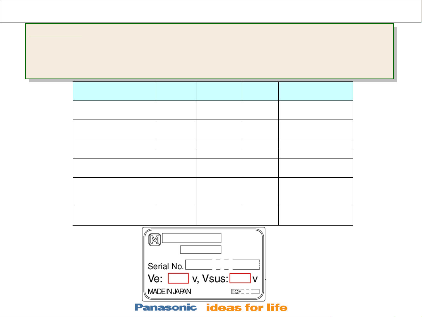
Name
Vsus TPVSUS
Ve
Vset TPVSET 240V ± 7V Fixed
(SC)
Vad TPVAD
Vscn TPVSCN
(SC) 4V
Vda
Test
Point
(SS)
TPVE
(SS)
(SC)
TPVDA
(SS)
Voltage Volume Remarks
Vsus ± 2V VR251
(P)
Ve ± 1V
-90V ± 1V VR6600
Vad+140V
±
75V + 1V,
-3V
VR6000
(SS)
(SC)
Fixed
Fixed
*
*
Page # 42
Page 45

Initialization Pulse adjustment
1. Input a white signal to plasma video input.
2. Set the picture controls as follows.
•Picture menu : Vivid
•Normal : Set
•Aspect : Full
3. Connect Oscilloscope to TPSC1 (SC).
Check that the flat section(T1) is less than
40µs.
Check and adjust so that the stand down
pulse(T2) period are each within
specification.
TH-58PZ750
TH-50PZ750
TH-58PZ700
TH-50PZ700
TH-42PZ700
Page # 43
Page 46

Procedure to Clean the Plasma TV Screen
Use a micro-fiber cloth (available in camera stores) or a clean 100% cotton cloth. No wood based
products (No paper towels, toilet paper, newspaper, etc.). Don't be fooled by "softness". Fine steel
wool can feel "soft". It's the fibers that scratch.
No chemicals like Windex, benzene, gasoline, ammonia, Soft Scrub, Lysol, 409, cheap "Window
cleaner".
First try to clean the screen dry (No chemicals or water). Quick light pressure strokes are better than
hard, "scrubbing" strokes. This method should safely remove fingerprints.
If more cleaning is needed:
Use a bit of distilled water to dampen the cloth and try the light pressure strokes.
LAST RESORT: A few drops of dishwashing (not dishwasher) solution dissolved in a lot of water to
make a weak solution. Try the quick light strokes again.
Dry clean the screen with the micro-fiber or 100% cotton cloth. The anti-reflective coating is like that
of a fine camera lens. If the coating is scratched or damaged,
Panasonic Parts Department stocks Plasma Screen Cleaner Solution (Micro-fiber Cloth Included)
1oz bottle= Part Number SCREENKLEEN1
MSRP $6.99
Dealer Cost $4.00
4oz bottle= Part Number SCREENKLEEN4
MSRP $14.95
Dealer Cost $8.00
Page # 44
Page 47

Glossary
A colorimeter is generally a tool that characterizes color samples to provide an objective measure
of color characteristics.
Colorimeter Sencore CP5000
A colorimeter (Sencore CP5000) measures the light output and tells you how to adjust the displays
red, green and blue cutoff and drive controls for a 6500 degree color temperature.
Color temperature: This control affects the entire palette of colors. Select the Warm or Low
option, which should come closest to the NTSC standard of 6,500 degrees Kelvin.
Foot-Lambert
This is a unit representing the amount of light emitted by a source in an area of one square foot.
The National Television Standards Committee (NTSC) (Analog color TV)
The Advanced Television Standards Committee (ATSC) (Digital TV system)
CIE: International Commission on Illumination
CIE (Commission Internationale de l'Êclairage)
The International Commission on Lighting; the body responsible for international recommendations
for photometry and colorimetry.
Page # 45
Page 48

The End
Thank you!
Thank you!
Good day!
Good day!
Page # 46
 Loading...