

Panasonic PAC service manual

Technical Tips
RAC/PAC
1

Table of contents
Page 3 Check list before you call
Page 4 Inverter technology
Page 5 26 thru 42k Btu units dual wiring diagram
Page 6 9 thru 24k Btu units wiring diagram
Page 7 Flexi Multi wiring diagram
Page 8 Trouble shooting for 9-24k Btu units
Page 9 Fault code retrieval procedure
Page 10-14 Indoor/Outdoor board trouble shooting procedure
Page 15 Trouble shooting for 26-42k Btu units
Page 16 EPROM replacement procedure
2

Check the items below before calling Tech Support+
Description of Problem and date:
1) Verify there is a matching set. On PAC make sure it was not changed from a C to a CH.
_____________________________________
2) Mod# & Serial#______________________________________________
3) New Install? ___ If not how long did it run? ______________________
4) Wrong unit installed in a low ambient application? ________________
5) Verify wiring is correct. Was shielded control wire used (PAC)? _____
6) What are the code/codes? _____________________________________
7) What is the voltage with load and no load? ______________________
8) What is VDC between 2&3 (RAC)? ____________________________
9) Are the service valves open? __________________________________
10) When power is first applied, does the expansion valve Tick? _______
11) Are the power lights on boards lit? ____________________________
12) How long does the unit run before locking out? __________________
13) What are the pressures & super heat while the unit is running? ________________
14) Does the indoor unit beep when a command is sent by the remote? Is it in the correct mode?
_________________________________________
15) Is the powers relay energized (RAC) in condenser? _______________
16) Is the transformer on the indoor unit good (PAC)? ______________
17) Is there a condensation pump and is it wired correctly? Is the safety used and how is it wired?
_______________________________________
18) Have you put the unit into diagnostic mode (RAC)? If so what is the code?
________________________________________________________
19) Is there a red power light on the outdoor board (RAC)? __________
20) What lights are on and are they flashing? ______________________
*RAC is any 9-24,000 BTU model or any Flexi Multi model.
*PAC is any 26-42,000 BTU model.
How was the problem resolved?
3

Caution for Installation
Higher Pressure (R410A is 1.6 times higher than R22.)
Compressor oil is different.
R410A uses Polyol Esther Oil (Synthetic fluid)
Different Gauge-manifold, Charge hose, etc., must be used for R410A.
Near-Azeotrope Type Refrigerant
Only charge the refrigerant in liquid form.
For Technical Information or Parts: call 1-800-851-1235 or visit our website: www.sanyohvac.com
INVERTER TECHNOLOGY
• The DC motor uses powerful Neodymium magnets, which are approximately 15-20 times stronger than the ferrite magnets used in
conventional AC compressors. This, combined with precise digital control gives the SANYO DC compressor an operation rate of 15-20%
higher than that of a conventional AC compressor.
• The SPW outdoor units utilize the latest SANYO twin rotary compressor in which perfectly balanced dual rotors revolve smoothly and
efficiently to provide powerful, quiet and vibration free performance.
• Can operate down as low as 23% of total outdoor unit capacity.
• An Inverter compressor is designed to vary its speed as the demands in the room change. Inverter compressors are designed to Soft Start
therefore causing no dips in power supply.
• Single phase AC power is supplied to the outdoor unit where it is rectified and converted into DC power to drive the compressor the
input frequency is then modified to allow the compressor to run at a variety of speeds.
• As the compressor speed decreases, the amount of refrigerant entering the indoor unit also decreases. This results in a more comfortable
environment as the unit only produces the appropriate amount of cooling or heating required at that time - no more temperature swings.
• Inverter compressors have been shown to reduce power consumption by as much as 60% when compared to conventional fixed speed
equivalents.
• Taking inverter technology to a new level of comfort
4
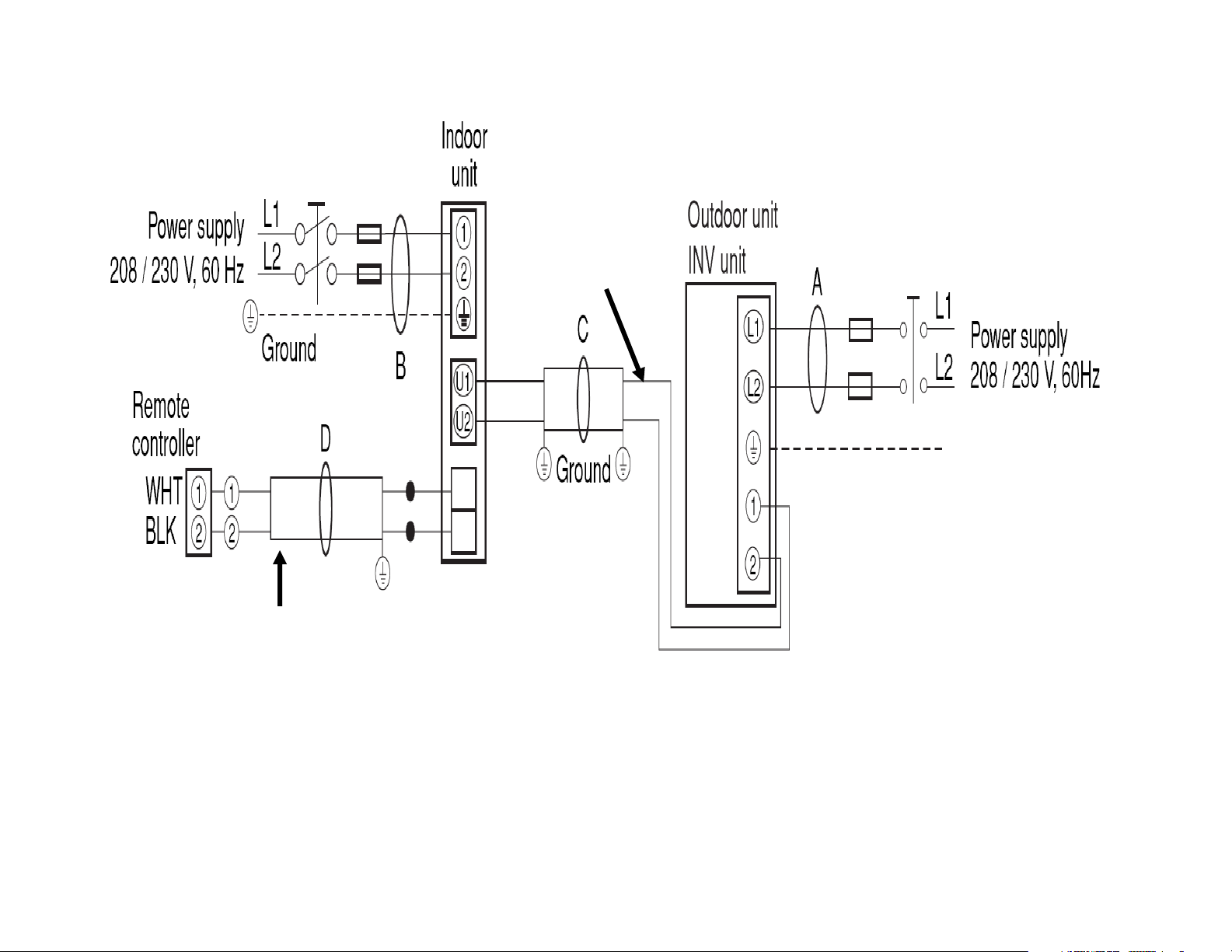
DUAL – CIRCUIT WIRING (26 - 42,000 BTU’s Models)
18-2
Shielded Wire
5 VDC
12 – 15 VDC
18-2 Shielded Wire
5
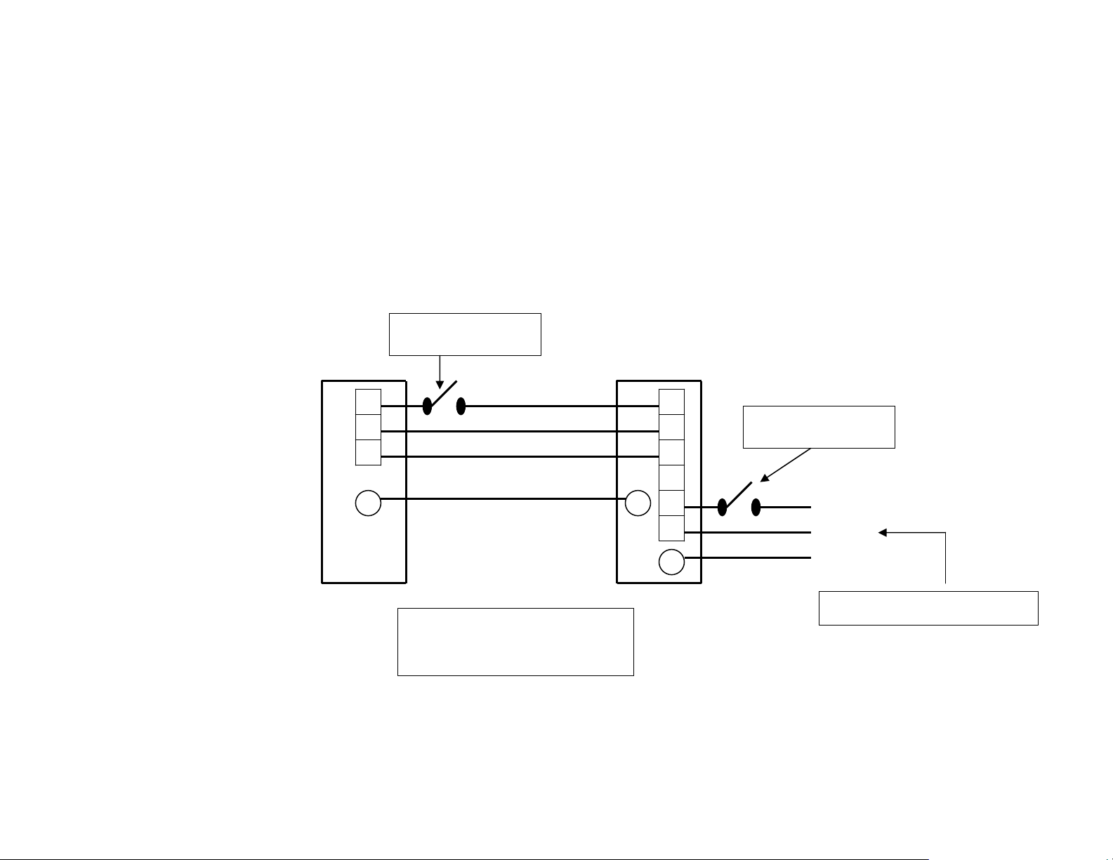
RAC Single Split System (A/C & HP)
¾
Installation wiring for 115 volt single split systems
¾ Note: The 9,000 & 12,000 BTU models in a single split
Combination requires a 115 volt power supply.
Disconnect Switch
(Field Supplied)
1
2
3
G G
Indoor Unit
Typical Installation Wiring
C-CL0971 & CH0971
For
C-CL1271 & CH1271
:
Hot
Neutral
12-15 VDC Signal
1
2
3
4
5
6
G
Outdoor Unit
Disconnect Switch
(Field Supplied)
Hot
Neutral
Ground
115 VAC (Power Supply)
6
 Loading...