

Page 1
Manufactured by:
81-IN3013-9922
Before attempting to connect or operate this product, please read these instructions completely.
for
MODEL: P9000HW•HC•HP
PRECAUTIONS ON INSTALLATION
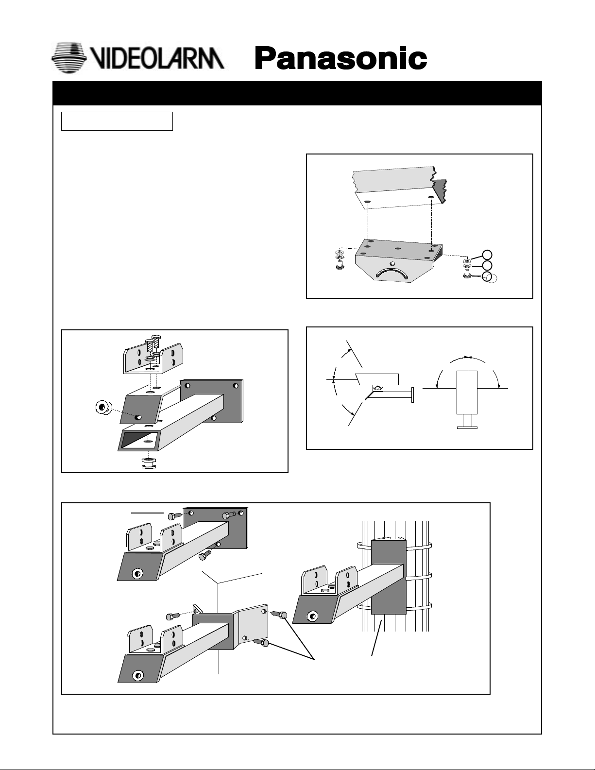
• The mounting brackets P9000HW, P9000HC or P9000HP
are designed for outdoor use and can support the
WV-7140 or WV-7135 housings.
The P9000HW is a wall mount bracket.
The P9000HC is a corner mount bracket.
The P9000HP is a pole mount bracket.
• Combined weight of camera, lens, housing, and pan/tilt
must not exceed 85 lbs. (38 kg).
• Select a location where the combined weight of the
bracket, housing, and camera can be properly sup ported.
INSTALLATION
1. Assemble bottom of swivel head and cable guard plate
to the end of the main bracket body as shown at the
right, by using the bolts provided. Place one rubber
grommet provided in the hole found on the cable guard
plate.
PRODUCT INSTRUCTIONS
3. Mount the camera housing on the top of the swivel head
and firmly attach it with two hex head bolts, lock washers
and flat washers.
HOUSING
6
2
3
7
5
TOP OF
SWIVEL
4. Adjust the camera direction with the four bolts of the
bracket and tighten the bolts firmly after adjustment.
2
2. Mount entire assembly in desired location. (Mounting
hardware is not included.)
NOT PROVIDED
P9000HW
60°
60°
90°
P9000HP
90°
P9000HC
NOT PROVIDED
Page 2
3.000"
45°
1.500"
3.000"
2.000"
17.250"
4.000"
21.440"
0
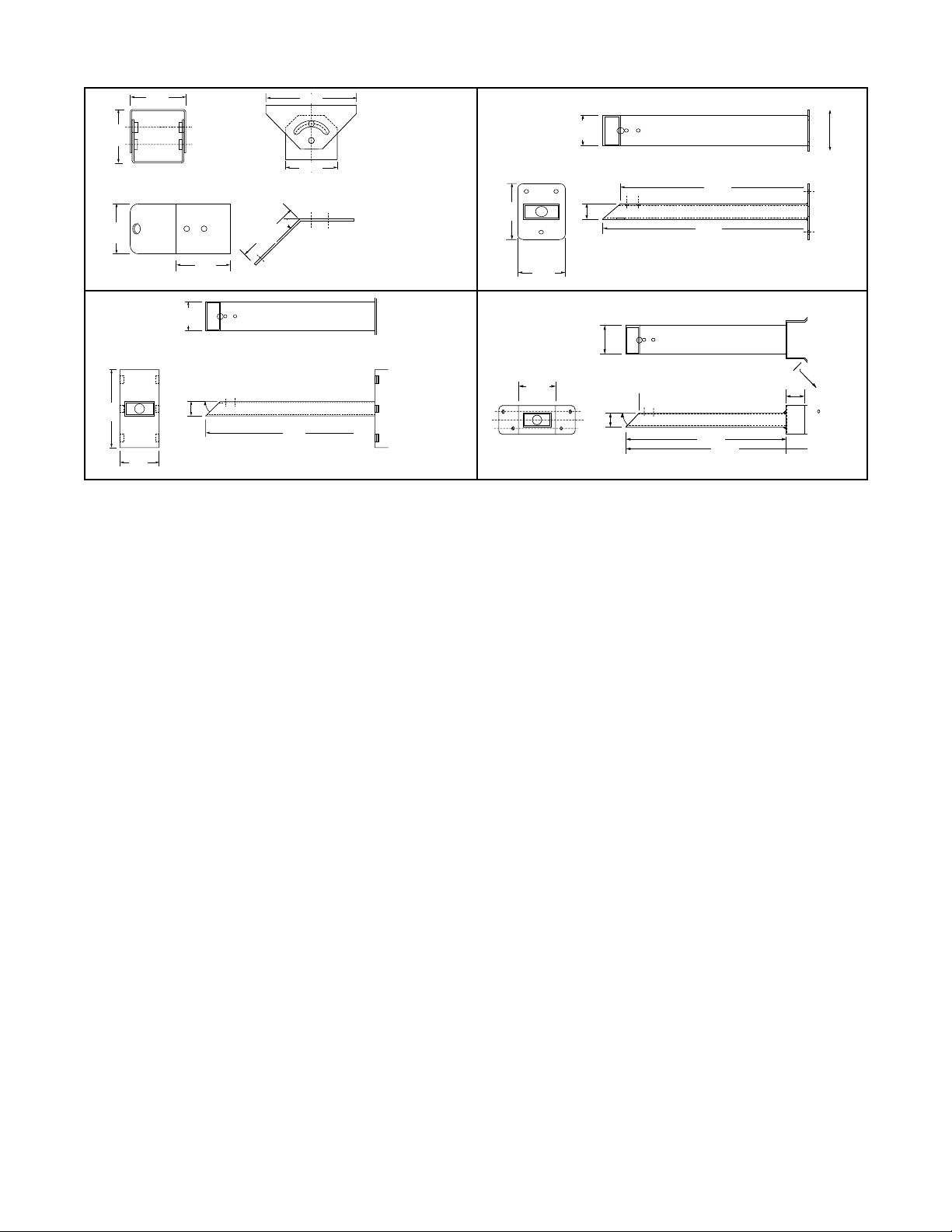
OUTLINE DRAWINGS
3.200"
3.200"
FRONT VIEW
5.250"
3.000"
SIDE VIEW
SWIVEL HEAD
INCLUDED WITH
ALL THREE UNITS
45°
3.750"
CABLE GUARD
SIDE VIEW
17.250"
P9000HP
8.000"
3.000"
4.000"
TOP VIEW
1.500"
3.125"
3.000"
45°
SPECIFICATIONS
Dimensions (including swivel brackets): P9000HW 17.375" x 4" x 6"
P9000HP 18.625" x 4" x 7.750"
P9000HC 21.437" x 4" x 5.250"
Weight: 9 lbs
Load Weight: 85 lbs. (38kgs)
5.500"
4.000"
3.000"
1.500"
15.750"
17.250"
P9000HW
P9000HC
STANDARD ACCESSORIES (Supplied)
1. M8-1.25 x 20 mm Hex Hd Bolt (6)
2. M8 Flat washer (8)
3. M8 Lockwashers (8)
4. Rubber Grommet (2)
5. M8-1.25 x15MM Hex Hd Bolt (2)
- 2 -
Page 3

1. Read Instructions - All the safety and operating instructions
!
should be read before the unit is operated.
2. Retain Instructions - The safety and operating instructions
should be retained for future reference.
3. Heed Warnings - All warnings on the unit and in the operating
instructions should be adhered to.
4. Follow Instructions - All operating and user instructions should
be followed.
5. Electrical Connections - Only a qualified electrician should
make electrical connections.
6. Attachments - Do not use attachments not recommended by the
product manufacturer as they may cause hazards.
7. Cable Runs - All cable runs must be within permissible distance.
8. Mounting - This unit must be properly and securely mounted to
a supporting structure capable of sustaining the weight of the
unit. Accordingly:
a. The installation should be made by a qualified service
person, and should conform to all local codes.
b. Care should be exercised to select suitable hardware to
install the unit, taking into account both the composition of the
mounting surface and the weight of the unit. Be sure to
periodically examine the unit and the supporting structure to
make sure that the integrity of the installation is intact. Failure
to comply with the foregoing could result in the unit separating
from the support structure and falling, with resultant damages
or injury to anyone or anything struck by the falling unit.
SAFETY PRECAUTIONSIMPORTANT SAFEGUARDS
CAUTION
RISK OF
ELECTRIC SHOCK!
CAUTION: TO REDUCE THE RISK OF
ELECTRICAL SHOCK, DO NOT EXPOSE
COMPONENTS TO WATER OR MOISTURE.
The lightning flash with an arrowhead symbol,
within an equilateral triangle, is intended to
alert the user to the presence of non-insulated
"dangerous voltage" within the product's
enclosure that may be of sufficient magnitude
to constitute a risk of electric shock to persons.
The exclamation point within an equilateral
triangle is intended to alert the user to
!
UNPACKING
Unpack carefully. Electronic components can be
damaged if improperly handled or dropped. If an item
appears to have been damaged in shipment, replace it
properly in its carton and notify the shipper.
presence of important operating and
maintenance (servicing) instructions in the
literature accompanying the appliance.
Be sure to save:
1. The shipping carton and packaging material. They are the
safest material in which to make future shipments of the
equipment.
2. These Installation and Operating Instructions.
SERVICE
For service on Panasonic/Videolarm equipment contact:
Panasonic Technical Center
54 West Gude Dr.
Rockville MD 20850-1150
Phone: 301-762-5125
Fax: 301-251-0347
PANASONIC TECHNICAL SUPPORT
1-800-528-6747
9:00 AM - 5:00 PM EASTERN TIME
- 3 -
 Loading...