

Panasonic OH10010 Datasheet
GaAs Hall Devices
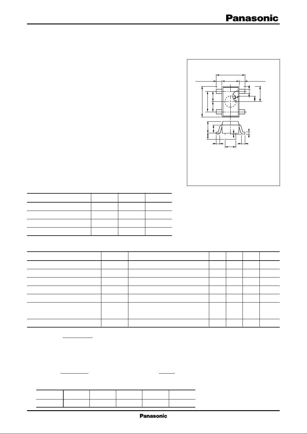
1.5 ± 0.2
φ 1.0 ± 0.025
0.5 ± 0.1
1.9 ± 0.2
2.9 ± 0.2
1.45±0.2
(0.5 R)
0.8
0.95 0.95
0.4 ± 0.2 0.4 ± 0.2
23
14
1.1
+ 0.2
− 0.1
0.16
+ 0.1
− 0.06
2.8
+ 0.2
− 0.3
0 to 0.1
+0.1
−0.05
0.4
0.5 R
0.65 ± 0.150.65 ± 0.15
OH10010
GaAs Hall Device
Magnetic sensor
■ Features
•
Hall voltage: typ. 105 mV (V
•
Input resistance: typ. 0.75 kΩ
•
Satisfactory linearity of GaAs hall voltage with respect to the
magnetic field
•
Small temperature coefficient of the hall voltage: β ≤ − 0.06%/°C
•
Mini type (4-pin) package with positioning projection. Allowing
automatic insertion through the magazine package.
■ Applications
•
Various hall motor (VCR, phonograph, VD, CD, and FDD)
•
Automotive equipment
•
Industrial equipment
•
Applicable to wide-varying field (OA equipment, etc.)
■ Absolute Maximum Ratings Ta = 25°C
Parameter Symbol Rating Unit
Control voltage V
Power dissipation P
Operating ambient temperature
Storage temperature T
= 6 V, B = 0.1 T)
C
C
D
T
opr
stg
150 mW
−30 to +125 °C
−55 to +125 °C
12 V
Unit : mm
1 : VH Output (−) side
2 : V
Input (−) side
C
3 : V
Output (+) side
H
4 : V
Input (+) side
Mini Type Package (4-pin) with positioning projection
C
Marking Symbol: ON
■ Electrical Characteristics Ta = 25°C
Hall voltage
Unequilibrium ratio
Input resistance R
Output resistance R
Temperature coefficient of hall voltage
Temperature coefficient of input α IC = 1 mA, B = 0 T 0.3 %/°C
resistance
Linearity of hall voltage
Note) *1: VH =
Parameter Symbol Conditions Min Typ Max Unit
1
*
2, 4
*
V
H
V
HO
IN
OUT
VC = 6 V, B = 0.1 T 80 105 130 mV
VC = 6 V, B = 0 T ±19 mV
IC = 1 mA, B = 0 T 0.5 0.75 kΩ
IC = 1 mA, B = 0 T 1.5 5 kΩ
β IC = 6 mA, B = 0.1 T −0.06 %/°C
3
V
+
H
*
+V
−
H
γ IC = 6 mA, B = 0.1 T/0.5 T 2 %
2
*2: Output pin voltage under no-load (B = 0) condition
*3: The linearity γ of VH is a percentage of a difference between cumulative sensitivity of KH1 and KH5 which are measured
respectively at B = 0.1 T and 0.5 T to their average. That is,
*4:VHO rank classification
KH5−K
H1
(the cumulative sensitivity KH =
γ =
1/2(KH1+KH5)I
C
V
・B
H
)
Class A B C D E
VHO (mV) +19 to +9 +12 to +2 +5 to −5 −2 to −12 −9 to −19
1
OH10010
GaAs Hall Devices
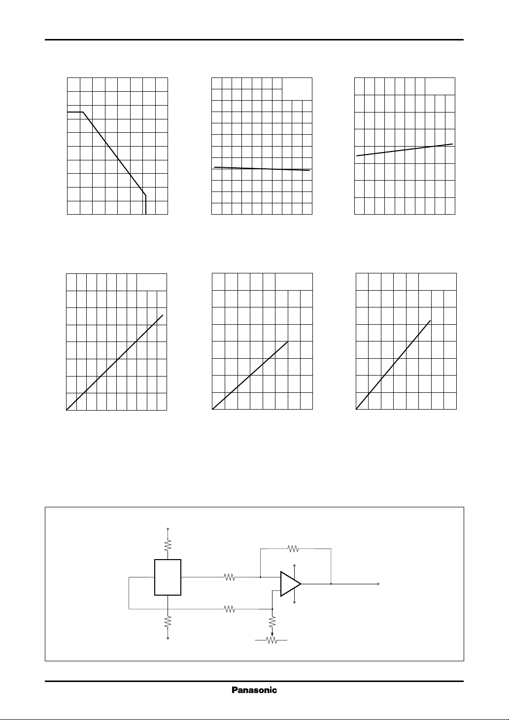
PD T
200
180
)
160
mW
140
(
D
120
100
80
60
Power dissipation P
40
20
0
02040 8060 140120100 160
Ambient temperature Ta (°C
VH B
1 600
1 400
1 200
)
mV
(
1 000
H
800
600
Hall voltage V
400
200
0
0 0.2 0.4 0.6 0.8 1.0
Magnetic flux density B (T
a
VC = 6 V
= 25°C
T
a
240
200
)
mV
160
(
H
120
80
Hall voltage V
40
0
)
−40 0 40 80 120
Ambient temperature Ta (°C
V
320
280
240
)
mV
(
200
H
160
120
Hall voltage V
80
40
0
0 4 12 162 6 10 148
VH T
)
Control current IC (mA
H
I
a
C
B = 1 kG
= 6 mA
I
C
B = 1 kG
= 25°C
T
a
1 600
1 400
)
1 200
Ω
(
IN
1 000
800
600
400
Input resistance R
200
0
)
320
280
240
)
mV
(
200
H
160
120
Hall voltage V
80
40
0
0 4 12 162 6 10 148
)
RIN T
−40 0 40 80 120
a
B = 0
= 1 mA
I
C
Ambient temperature Ta (°C
VH V
Control voltage VC (V
C
B = 1 kG
= 25°C
T
a
)
)
■ Typical Drive Circuit
2
+9 V
4
31
2
−9 V
−V
+9 V
−
+
−9 V
+V
 Loading...