

Page 1
INSTRUCTION MANUAL
Multiple Voltage Beam Sensor
NX5 Series
Thank you very much for using SUNX sensors. Please read this
Instruction Manual carefully and thoroughly for the correct and optimum
use of this sensor. Kindly keep this manual in a convenient place for
quick reference.
This product is not a safety sensor. Its use is not
intended or designed to protect life and prevent body
injury or property damage from dangerous parts of
machinery. It is a normal object detection sensor.
1
Type
Model
Light-ON
No.
Item
Dark-ON
Sensing range
Sensing object
Thru-beam
Long sensing range
NX5-M10RA
NX5-M10RB
10m
NX5-M30A
NX5-M30B
30m
Opaque object of
¿20mm or more (Note 4)
Hysteresis
Supply voltage
Power consumption
Output
24 to 240V AC±10% or 12 to 240V DC±10%, Ripple P-P: 10% or less
Emitter: 1VA or less
Receiver: 2VA or less
Relay contact 1c
Æ Switching capacity:
Æ Electrical life:
Æ Mechanical life:
Emitter: 1.5VA or less
Receiver: 2VA or less
250V AC 1A (resistive load)
30V DC 2A (resistive load)
100,000 or more operations (at AC rated load)
500,000 or more operations (at DC rated load)
100,000,000 or more operations
Response time
Operation indicator
Stability indicator
Green LED (lights up during the stable Light or the stable Dark condition)
Power indicator
Sensitivity adjuster
Automatic interference
prevention function
Variable adjuster Variable adjuster Variable adjuster
Use optional
interference
prevention filters
Red LED (lights up when the output is ON)
Red LED
(lights up when power is on)
Protection
Ambient temperature
Ambient humidity
Emitting element
Material
Cable
Weight
Accessories
Notes: 1)
The retroreflective type sensor with polarizing filters may not stably detect specular or
glossy objects through transparent film since light is polarized by the transparent film.
(Example of sensing objects)Æ Can wrapped by clear film
2)
The sensing range and sensing object for the retroreflective type sensor is
specified for the RF-230 reflector. Further, the sensing range is the possible setting
range for the reflector. The sensor can detect an object less than 0.1m away.
3)
The sensing range of the diffuse reflective type sensor is specified for white nonglossy paper (200 200mm).
4)
If slit masks (optional) are fitted, an object as small as 3 6mm can be detected.
5)
In case the sensor is to be used at an ambient temperature of —15…C, or less,
please contact our office.
—25 to +55°C (No dew condensation or icing allowed) (Note 5), Storage: —30 to +70°C
35 to 85% RH, Storage: 35 to 85% RH
Red LED Infrared LED Red LED Infrared LED
Enclosure, Lens and Cover: Polycarbonate, Front cover: Acrylic (retroreflective type sensor only)
0.3mm2 5-core (emitter of thru-beam type sensor: 2-core) cabtyre cable, 2m long
Emitter: 100g approx.
Receiver: 140g approx.
Screwdriver for sensitivity
adjustment: 1 No.
Reflector cannot be
placed in this range.
Sensor
Emitter: 125g approx.
Receiver: 140g approx.
Æ Aluminum sheet covered by plastic film
Æ
Gold or silver color (glossy) labels or wrapping paper
Actual sensing range
of the sensor
0.1m
Setting range
of the reflector
Reflector
Retroreflective
With polarizing filters (Note1)
NX5-PRVM5A
NX5-PRVM5B
0.1 to 5m (Note 2)
Opaque, translucent or
specular objects of
¿50mm or more (Note 2)
Long sensing range
NX5-RM7A
NX5-RM7B
0.1 to 7m (Note 2)
Opaque or translucent
object of ¿50mm
or more (
Diffuse reflective
NX5-D700A
NX5-D700B
700mm (Note 3)
Opaque, translucent or
transparent object
Note
2)
15% or less of
operation distance
2VA or less
10ms or less
(Two units of sensors can be mounted closely.)
Incorporated
IP66 (IEC)
140g approx.
RF-230 (reflector): 1 No.
Screwdriver for sensitivity adjustment:
1 No. (NX5-PRVM5 )
5m (NX5-RM7 : 7m)
Reflector
Screwdriver for sensitivity
adjustment:1 No.
2
Make sure to carry out wiring in the power supply off condition.
Take care that wrong wiring will damage the sensor.
Do not run the wires together with high-voltage lines or power lines or put
them in the same raceway. This can cause malfunction due to induction.
Verify that the supply voltage variation is within the rating.
If power is supplied from a commercial switching regulator, ensure that the frame
ground (F.G.) terminal of the power supply is connected to an actual ground.
Do not use during the initial transient time (50ms) after the power supply
is switched on.
In case noise generating equipment (switching regulator, inverter motor,
etc.) is used in the vicinity of this product, connect the frame ground
(F.G.) terminal of the equipment to an actual ground.
Extension up to total 100m, or less, is possible with 0.3mm2, or more, cable.
When connecting an inductive load, such
as a DC relay, connect a surge absorber
as shown in the right figure.
Take care that the sensor is not directly
exposed to fluorescent light from a rapidstarter lamp or a high frequency lighting
device, as it may affect the sensing
performance.
This sensor is suitable for indoor use only.
Avoid dust, dirt, and steam.
Take care that the sensor does not come in direct contact with water, oil,
grease, or organic solvents, such as, thinner, etc.
DC relay
Sensor
COM.
NO
NC
Output relay
Make sure to
connect a surge
absorption diode.
+
—
3
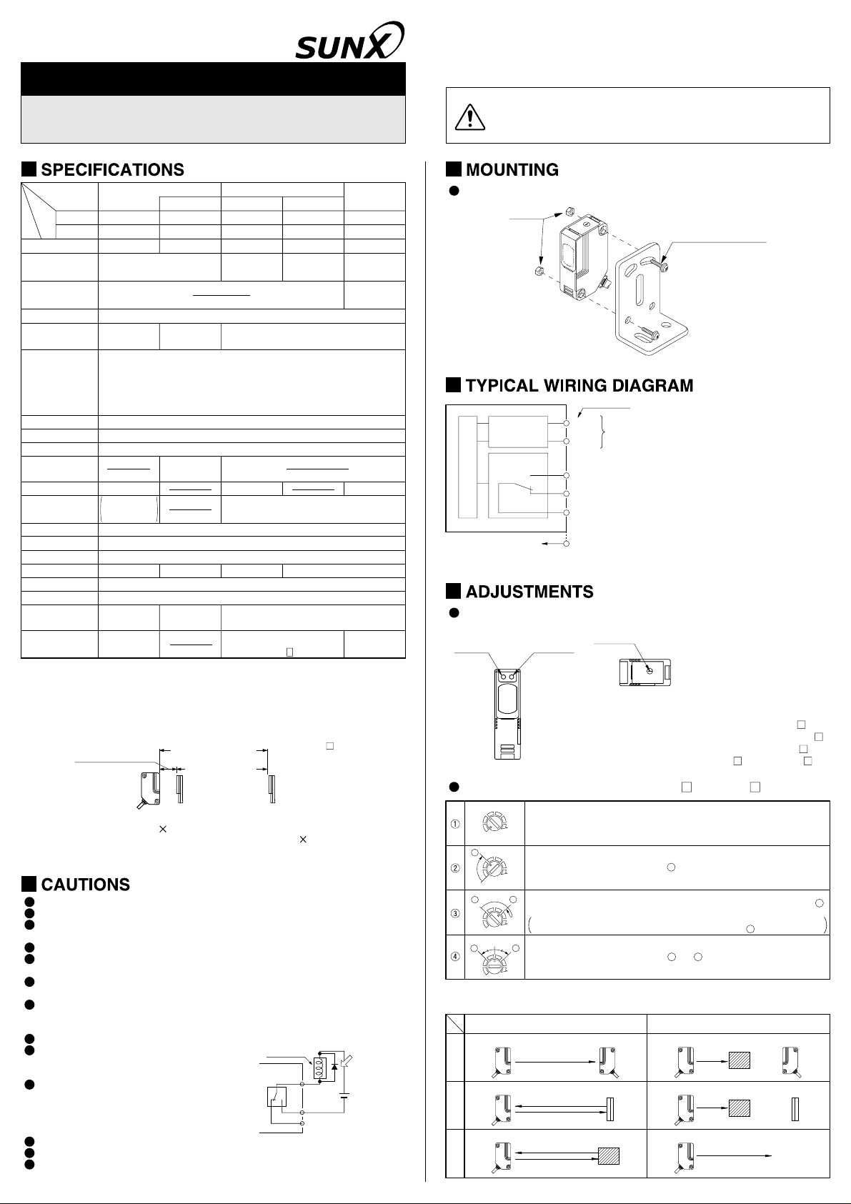
The tightening torque should be 0.8NÆm or less.
M4 nuts
Sensor
mounting bracket
(Optional)
M4 (length 25mm) screw
with washers
4
Color code
Multi-voltage
power supply
circuit
Output relay
Sensor circuit
Internal ciuircit
Brown
Blue
Black
Gray
White
……
……
……
Supply voltage
24 to 240V AC±10%
or
12 to 240V AC±10%
NO
NC
COM.
Note: The emitter of thru-beam type sensor has two wires for the power supply (+V and 0V) only.
5
Top face
Stability
indicator
(Green)
(Note 1) (Note 2)
Operation
indicator
(Red)
Notes: 1)
Sensitivity adjustment (excluding NX5-M30 , NX5-RM7 )
Turn the sensitivity adjuster fully counterclockwise to the minimum
MIN.
A
A
MIN.
Optimum position
A
MIN. MAX.
Note:
Use the accessory adjuster screwdriver to turn the adjuster slowly. Turning with excessive
strength will damage the adjuster.
Thru-beam
Retroreflective
Diffuse reflective
sensitivity position, MIN.
MAX.
In the light received condition, turn the sensitivity adjuster slowly
clockwise and confirm the point where the sensor enters the ‘Light’
state operation.
MAX.MIN.
In the light interrupted state, turn the sensitivity adjuster further clockwise until the
B
sensor enters the ‘Light’ state operation and then bring it back to confirm point
where the sensor just returns to the ‘Dark’ state operation.
If the sensor does not enter the ‘Light’ state operation even when the sensitivity
MAX.
adjuster is turned fully clockwise, this extreme position is point .
B
The position at the middle of points and is the optimum sensing position.
Light received condition Dark condition
Emitter Receiver
Sensor Reflector
Sensor
Sensitivity
adjuster
(Note 3)
Not incorporated on the emitter of thru-beam type
sensor.
Not incorporated on the emitter of
2)
NX5-M10R
the power indicator (red) on the emitter of NX5-M30 .
Not incorporated on the emitter of
3)
emitter and receiver of
Sensing object
NX5-M30
A
A
B
Emitter Receiver
Sensor Reflector
Sensor
NX5-M10R
, or
B
Sensing object
Sensing object
NX5-RM7
. It is
, the
.
B
Page 2
Light beam alignment
Thru-beam type sensor
Placing the emitter and the receiver face to face along
a straight line, move the emitter in the up, down, left
and right directions, in order to determine the range of
the light received condition with the help of the
operation indicator. Then, set the emitter at the center
of this range.
Similarly, adjust for up, down, left and right angular
movement of the emitter.
Further, perform the angular adjustment for the
receiver also.
Check that the stability indicator lights up.
Retroreflective type sensor
Placing the sensor and the reflector face to face along
a straight line, move the reflector in the up, down, left
and right directions, in order to determine the range of
the light received condition with the help of the
operation indicator. Then, set the reflector at the
center of this range.
Similarly, adjust for up, down, left and right angular
movement of the reflector.
Further, perform the angular adjustment for the
sensor also.
Check that the stability indicator lights up.
Relation between output and indicators
lights up turns off
In case of Light-ON In case of Dark-ON
Stability indicator
Operation indicator
Output
Sensing condition
Stable light receiving
ON
Unstable light receiving
Unstable light interrupted
OFF ON
Stable light interrupted
Output
OFF
6
The retroreflective type and the diffuse
reflective type sensors are incorporated with
an automatic interference prevention
function, so that two sensors can be
mounted closely.
Sensing object
Receiver
Sensing object
Sensor
Operation indicator
Stability indicator
Emitter
Reflector
9
As light is polarized by a transparent film or membrane, NX5-PRVM5
may not detect an object covered or wrapped by transparent film. In that
case, take the following steps.
(Example of sensing objects)
•
Can wrapped by clear film
•
Aluminum sheet covered by plastic film
•
Gold or silver color (glossy) labels or wrapping paper
(Steps)
•
Tilt the sensor with respect to the sensing object upon fitting.
•
Reduce the sensitivity.
•
Increase the distance between the sensor and the sensing object.
10
With the slit mask, the sensor can detect an object as small as 3 6mm.
However, the sensing range is reduced when the slit mask is mounted.
How to mount
Fit the C portion of the slit mask in the groove A
Groove B
D
of the main body case.
Then press the slit mask against the main body
to fit the slit mask hook D portion in the groove B
of the main body case.
C
Groove A
How to remove
Insert a ‘minus’ screwdriver into the E portion of
the slit mask.
Slit mask
Lift the E portion up to remove the slit mask from
the main body case.
11
By mounting interference prevention filters, two sets
of NX5-M10R can be mounted close together.
The filters can be mounted by the same method as
for the slit masks.
There are two types of interference prevention
filters. The two sets of thru-beam type sensors
should be fitted with different types of interference
prevention filters.
Note: The filters cannot be used for NX5-M30 .
Fitted with
PF-NX5-H
Fitted with
PF-NX5-V
E
7
If interference occurs when using NX5-M10R , use the optional
interference filters (PF-NX5- ) to mount two sensors closely.
[For details, refer to INTERFERENCE PREVENTION FILTER (OPTIONAL).]
11
In case interference occurs when NX5-M10R , without interference
prevention filters, or NX5-M30 are mounted closely, we recommend
that the emitter and the receiver are placed alternatively at a distance, as
given below.
Further, if interference occurs even when the specified distance is kept,
place light barriers, etc.
Example:
Emitter
Keep sufficient distance
Receiver Emitter
Setting distance
In case of NX5-M10R
In case of NX5-M30
Receiver
: 1m approx. or more (for 10m setting distance)
2.5m approx. or more (for 30m setting distance)
:
8
Please take care of the
following points when detecting materials having a gloss.
Make L, shown in the
diagram, sufficiently long.
Install at an angle of 10 to 30
degrees to the sensing
object.
The retroreflective type
sensor with polarizing filters,
NX5-PRVM5 , does not
need such adjustment.
Glossy surface
10 to 30º
Sensor
Sensing object
The distance L should be
L
as long possible.
Reflector
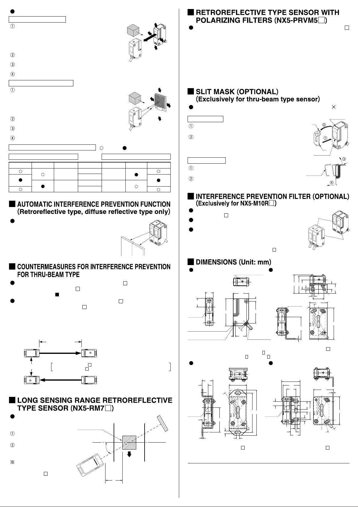
12
NX5 Series
18
20 (
Note 1
)
Beam axis
2-ø4.5 thru holes (for mounting)
2-M4 nut holders
(also on the opposite side)
20.5 for the retroreflective type sensor and
Notes: 1)
the diffuse reflective type sensor.
Not incorporated on the emitter of NX5-M10R
2)
emitter and receiver of NX5-M30 , or NX5-RM7 .
Sensitivity adjuster
62
5
35
4
25
(Note 2)
6
50
ø5.8 cable 2m
Mounting of MS-NX5-2 (Optional mounting bracket)
25
14
Beam axis
5
Note:
The drawing shows mounting of the
receiver of NX5-M10R .
56
t2
6.4
10º
40
90
104
6
Head Office
2431-1 Ushiyama-cho, Kasugai-shi, Aichi, 486-0901, Japan
Phone: +81-(0)568-33-7211 FAX: +81-(0)568-33-2631
Overseas Sales Dept.
Phone: +81-(0)568-33-7861 FAX: +81-(0)568-33-8591
Mounting of MS-NX5-1 (Optional mounting bracket)
(43)
40
21
Beam axis
51
t2
Note: The drawing shows mounting of the
receiver of NX5-M10R .
, the
Mounting of MS-NX5-3 (Optional mounting bracket)
(43)
40
21
10
Beam axis
Note: The drawing shows mounting of the
receiver of NX5-M10R .
6.4
6.4
5
12
22
5.2
6.4
10º
18
42
6
http://www.sunx.co.jp/ SUNX Limited
PRINTED IN JAPAN
12
ø6.4
25
40
45
10º
22
72
t2
64
 Loading...