How it Works
Log In / Sign Up
Buy Points
How it Works
FAQ
Contact Us
Questions and Suggestions
Users
Panasonic
Loading...
N
nn-sd778
2
NN-SD786S
2
NN-SD787
NN-SD797
NN-SD797S
NN-SD797S CPH
nn-sd945s
NN-SD947S
NN-SD957S
nn-sd962
NN-SD962S
4
NN-SD965S
Nn-sd967
2
nn-sd967s
3
nn-sd972
NN-SD972S
3
NN-SD975S
NN-SD977S
NN-SD978
Nn-sd986
2
NN-SD986S
2
NN-SD987
2
NN-SD987S
NN-SD99
NN-SD997
NN-SD997S
2
NN-SD997S CPH
NN-SE284B
NN-SE284S
NN-SE782S
NN-SE785S
2
NN-SE792S
2
NN-SE795S
NN-SE796S
NN-SE982S
nn-sE985EW
NN-SE985S
2
nn-sE985SW
NN-SE992S
NN-SE995S
NN-SE996S
NN-SF329H
NN-SF368M
NN-SF368X
NN-SF460M
NN-SF550
2
nn-sf550m
2
NN-SF560WRU
NN-SF564WQPQ
2
NN-SF574SQPQ
2
NN-SG158S
2
NN-SG626B
NN-SG626S
NN-SG626W
NN-SG636S
NN-SG636W
NN-SG656S
NN-SG656W
NN-SG676B
NN-SG676W
NN-SM220W
NN-SM221
2
NN-SM221W
2
NN-SM221WZPE
NN-SM321H
NN-SM330W
2
NN-SM330WZPE
NN-SM332W
nn-sn643
NN-SN648S CPH
nn-sn651
2
nn-sn651b
NN-SN651W
Nn-sn656
NN-SN656B
NN-SN656W
nn-sn657s
2
NN-SN658W CPH
nn-sn661
NN-SN661S
NN-SN665
NN-SN667
2
NN-SN667W
NN-SN668B CPH
NN-SN668W CPH
nn-sn671
NN-SN671S
NN-SN676
NN-SN676S
NN-SN676SX CPH
NN-SN677
NN-SN678S CPH
nn-sn67hs
nn-sn686
NN-SN733B
NN-SN733W
nn-sn736
NN-SN736B
NN-SN736W
NN-SN743B
Loading...
Loading...
Nothing found
NN-SG158S
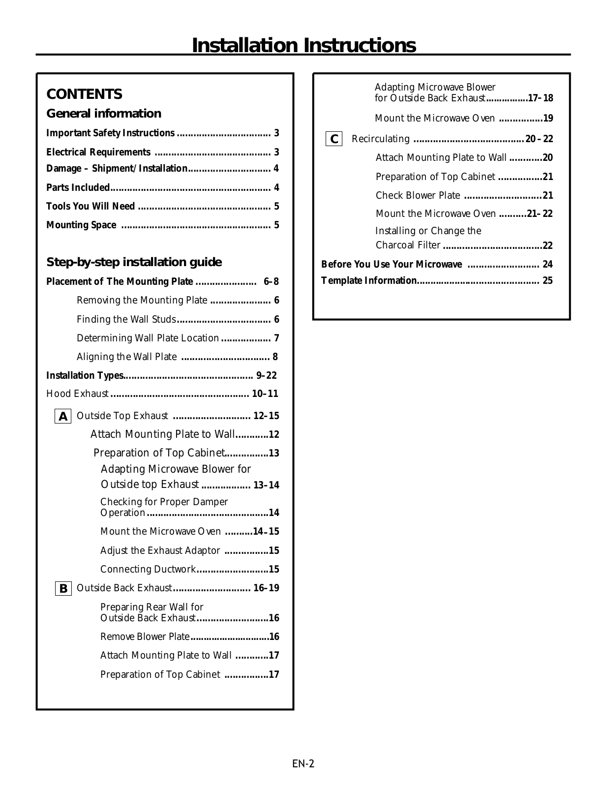
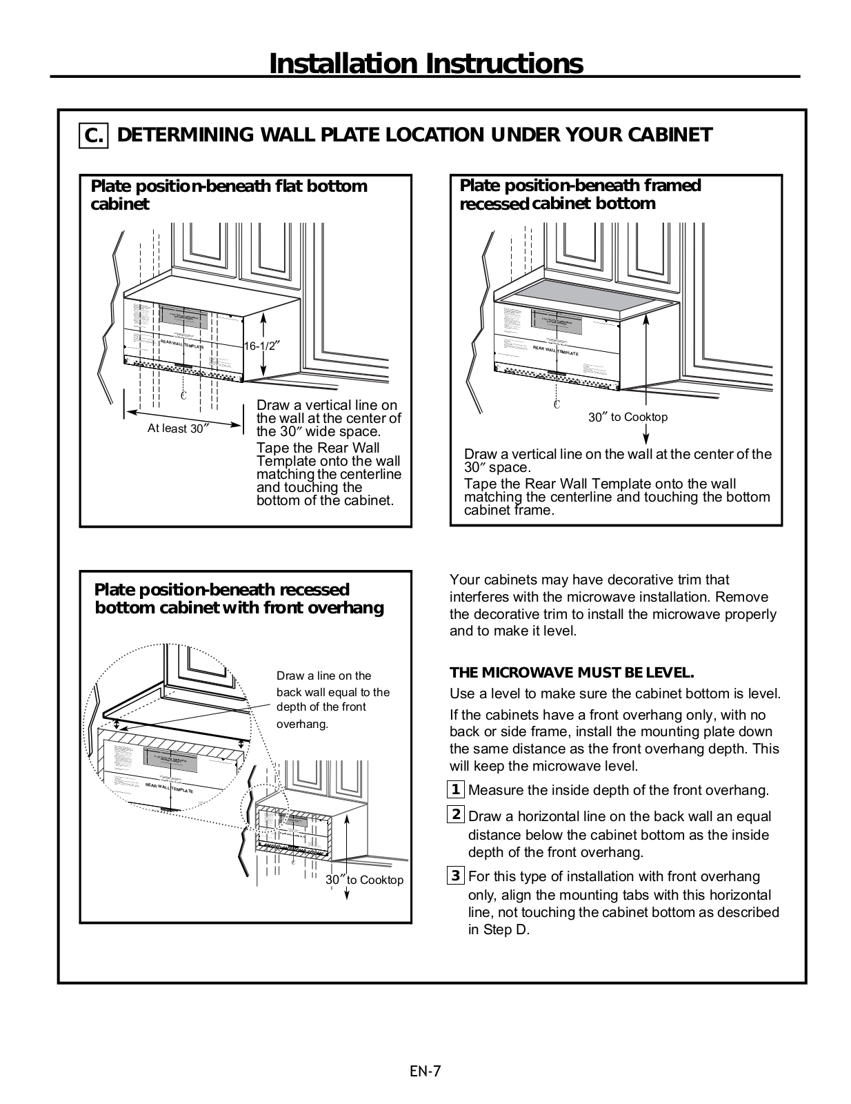
Installation Instructions
26 pgs
3.74 Mb
0
Owner’s Manual
30 pgs
2.21 Mb
0
Table of contents
Loading...
Panasonic NNSG158S Installation Instructions
...
Panasonic Installation Instructions
Download
Specifications and Main Features
Frequently Asked Questions
User Manual
Download
Loading...
+
18
hidden pages
Unhide
You need points to download manuals.
1 point = 1 manual.
You can buy points or you can get point for every manual you upload.
Buy points
Upload your manuals