

Panasonic NNSE284W INSTALLATION INSTRUCTIONS
Panasonic Over The Range Microwave Oven
INSTALLATION INSTRUCTIONS
Read carefully and keep these installation instructions
A
REQUIREMENTS FOR INSTALLATION
Installation of this product is safest and easiest when performed by two people. Before beginning the
installation, please read the following requirements to make sure you have everything you need to safely
install this product.
1. SUPPLY CIRCUIT AND GROUNDING REQUIREMENTS
This oven must be plugged into a 15 AMP or 20 AMP, 120 volt, 60 Hz, 3 prong grounded outlet. The outlet
must be connected to a separate 15 AMP or 20 AMP circuit of the proper voltage and frequency. No other
appliance should share the circuit. Wire size must conform to the requirements of the National Electric Code
or the prevailing local code for this kilowatt rating.
The recommended location for this outlet is inside the cabinet directly above where the oven is going to be
installed. This location is desirable because the power supply cord on the product is short. If an outlet is
not readily available, one should be installed by a qualified electrician and should conform to the National
Electric Code or the prevailing local code.
The installer must perform a ground continuity check on the outlet box to ensure that it is properly
grounded, and if it does not meet the electrical requirements of the product a qualified electrician should be
employed to correct any deficiencies.
2. MOUNTING SURFACE WEIGHT CAPACITY REQUIREMENTS
FOR PERSONAL SAFETY, ANY MOUNTING SURFACE FOR THIS PRODUCT MUST BE CAPABLE OF
SUPPORTING THE PRODUCT’S WEIGHT OF 55 lbs. (25 kg). PLUS ADDITIONAL OVEN LOADS OF UP
TO 22 lbs. (10 kg). FOR A TOTAL WEIGHT OF 77 lbs. (35 kg).
Proper installation of this product requires that the product be partially supported by the bottom surface of
the cabinet directly above the mounting location. Therefore reinforcing this bottom might be necessary if the
cabinet cannot support the weight requirement mentioned above.
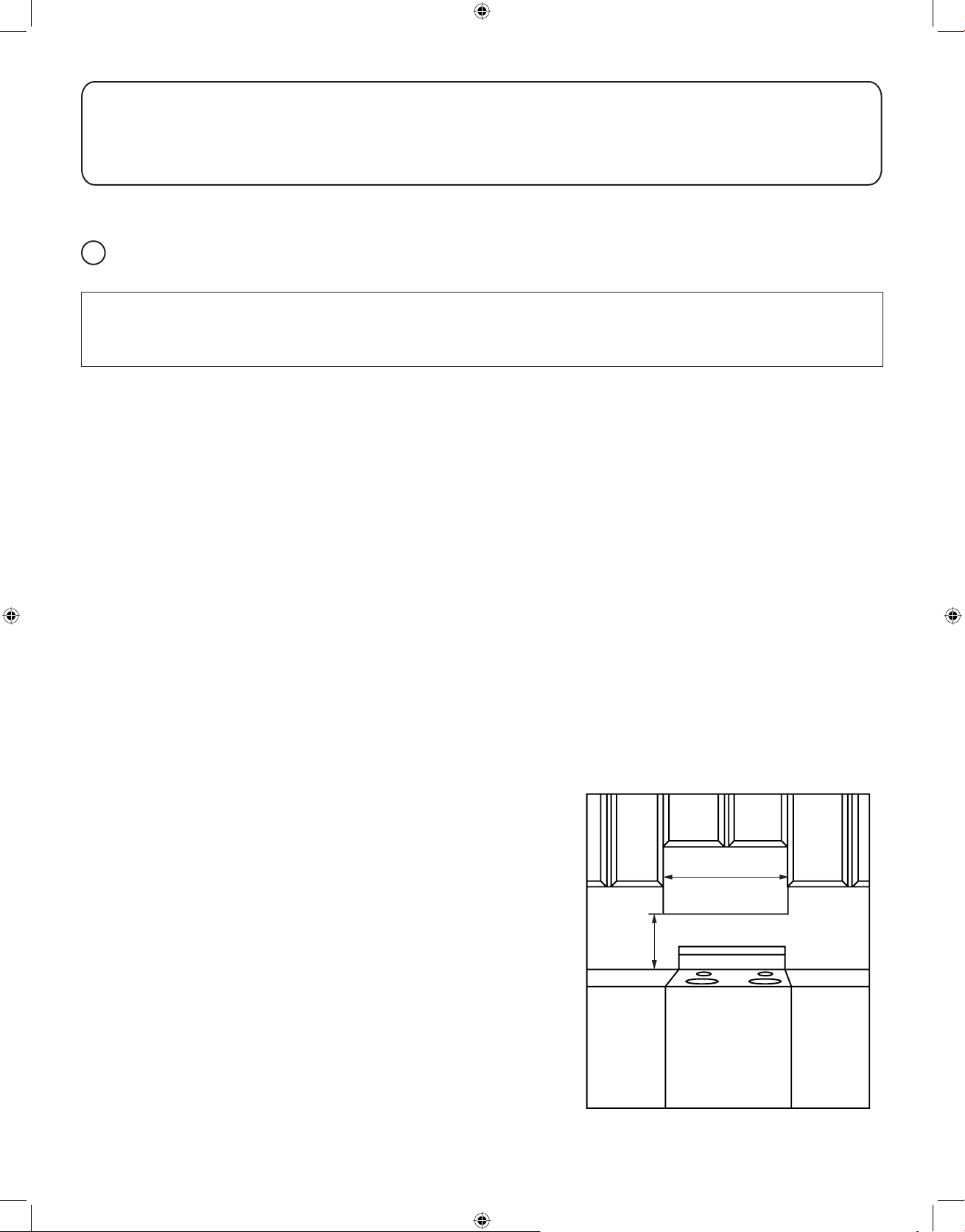
3. MOUNTING SPACE REQUIREMENT
Kitchen cabinet depth must be at least 12" (30.5 cm) and not
over 13" (33 cm).
A minimum width of 30" (76 cm) is required on a flat, vertical
wall for installation of this product.
This product is suitable for use above gas or electric cooking
equipment 36 in. or less. To reduce the risk of fire or electric
shock, install the oven at the clearance "H" specified below:
(Fig. A-1)
• Electric range:
H = 13
• Gas range:
H = 16" (40.6 cm) MINIMUM
5
/8" (34.6 cm) MINIMUM
H
30"
(76 cm)
F03138Q03CP
IP0109-51110
Printed in China
Fig. A-1
1
IP3297_F03138Q03CP_Eng_00_101028.indd 1IP3297_F03138Q03CP_Eng_00_101028.indd 1 2010-10-28 11:51:292010-10-28 11:51:29
4. EXHAUST REQUIREMENTS
This product is shipped for use in the top exhaust ventilation mode.
If you wish to install this product without using an exhaust duct, the exhaust must be recirculated through
the front grille and the charcoal filter. This product is shipped with a standard charcoal filter already installed.
The Charcoal Filter cannot be cleaned and should be replaced periodically every 6 to 12 months, or more
often if necessary.
When necessary to replace the charcoal filter, it can be purchased from your local Panasonic dealer.
The part number of the replacement charcoal filter is NN-CF203, refer to the following instructions for
replacement.
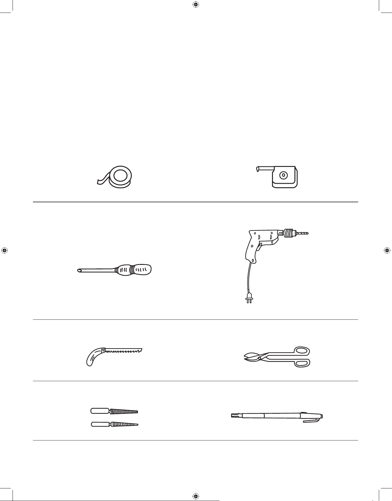
5. TOOL REQUIREMENTS
Adhesive Tape Tape Measure
Phillips Screwdriver Electric or Hand Drill
Electric or Hand Jigsaw Side Cutter or Tin Snipper
Metal File Marking Pen
2
IP3297_F03138Q03CP_Eng_00_101028.indd 2IP3297_F03138Q03CP_Eng_00_101028.indd 2 2010-10-28 11:51:292010-10-28 11:51:29
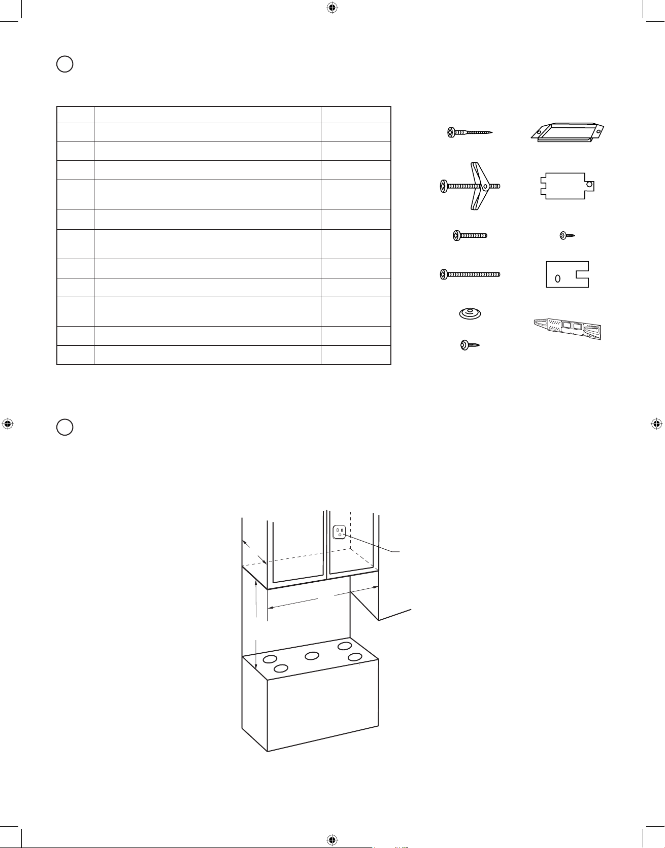
B
INSTALLATION HARDWARE
The installation hardware (
NO. NAME QUANTITY
Wood Screw 5/32" × 13/4" (5 × 45 mm) 4
q
Toggle Bolts 5/32" × 23/8" (5 × 60 mm) 4
w
5
e
e
Screw
-a
Screw (For cabinets with recessed bottom)
-b
5
/32" × 31/8" (5 × 80 mm)
Flat Washer 2
r
Screw (For E×haust Adaptor)
t
5
/32" × 3/8" (4 × 10 mm)
Exhaust Adaptor 1
y
Ventilation Exhaust Cover 2
u
Screw (For Ventilation Exhaust Cover)
i
1
/8" × 5/16" (3 × 8 mm)
Metal Brace 1
o
Bracket Assembly (at rear of product) 1
a
/32" × 11/2" (5 × 40 mm) 2
) packed with the products should include the following:
q~a
2
2
2
q y
w u
-a i
e
-b o
e
r
t
a
The installation hardware is taped on top of the oven.
C
INSTALLATION PROCEDURE
Remove the bracket assembly located on the rear of oven and remove all adhesive tape.
STEP 1: PRE-INSTALLATION CHECK POINTS
12"
MIN
30"
120V AC, min. 15A
separated line outlet
*D
• Electric range:
*D = 30" (76 cm) MINIMUM
• Gas range:
3
*D = 32
/8" (82 cm) MINIMUM
Fig. 1
3
IP3297_F03138Q03CP_Eng_00_101028.indd 3IP3297_F03138Q03CP_Eng_00_101028.indd 3 2010-10-28 11:51:292010-10-28 11:51:29
1. Confirm the separated line electric outlet. (Fig. 1)
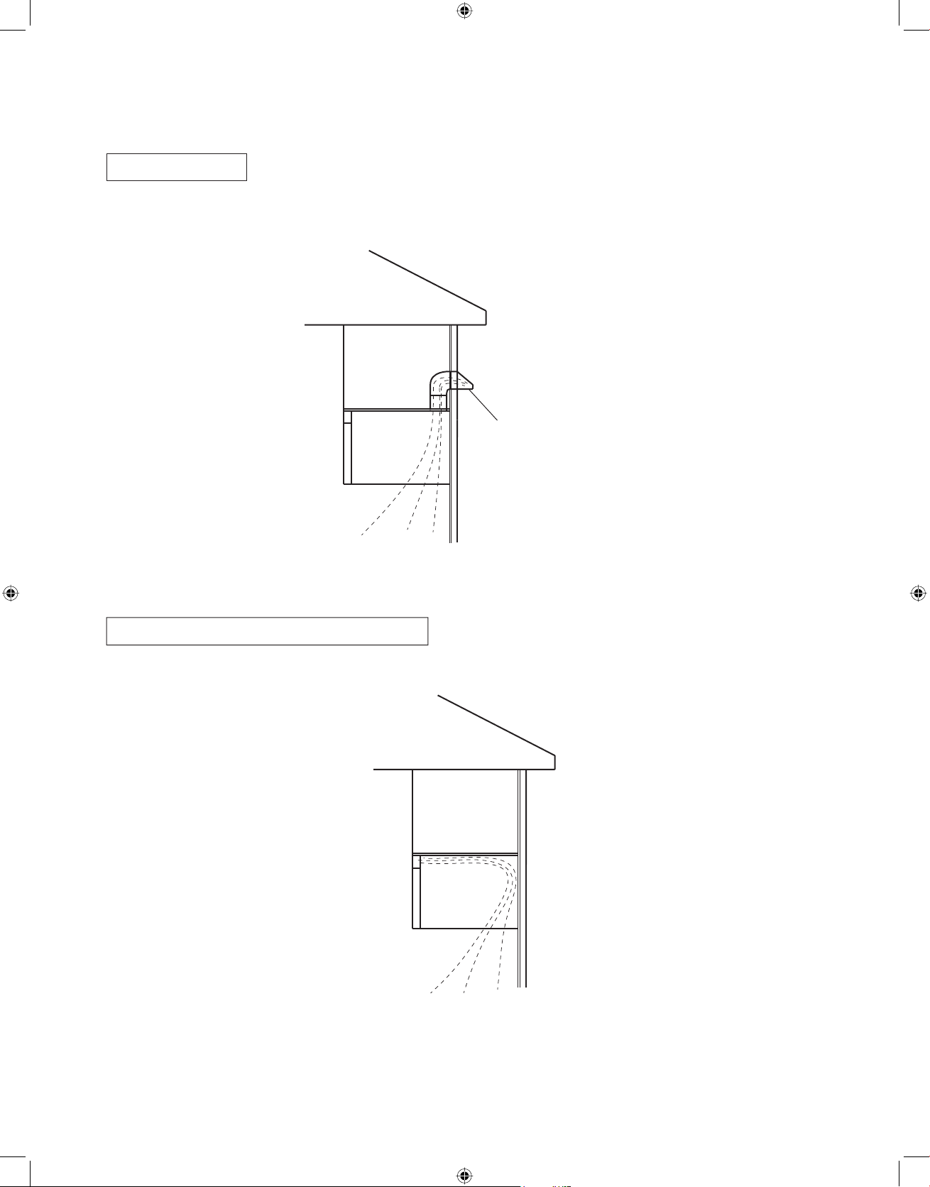
2. Exhaust Preparation: Select the type of ventilation required for your installation, and proceed to the
following instructions.
a. Top Exhaust
(Fig. 1-1)
This product is shipped ready for top exhaust ventilation mode use without adjusting the product.
Wall Cap with Flapper
Top Exhaust
Fig. 1-1
b. Recirculating (Non-vented, Ductless)
Recirculating (Non-vented, Ductless)
(Fig. 1-2)
Fig. 1-2
4
IP3297_F03138Q03CP_Eng_00_101028.indd 4IP3297_F03138Q03CP_Eng_00_101028.indd 4 2010-10-28 11:51:292010-10-28 11:51:29
If your oven is to be vented into the kitchen, the standard charcoal filter is already installed in your oven, ready
for recirculating mode.
When you replace the charcoal filter, refer to the instructions in the Operating Instructions (Maintenance/Care
and Cleaning of Your Microwave Oven).
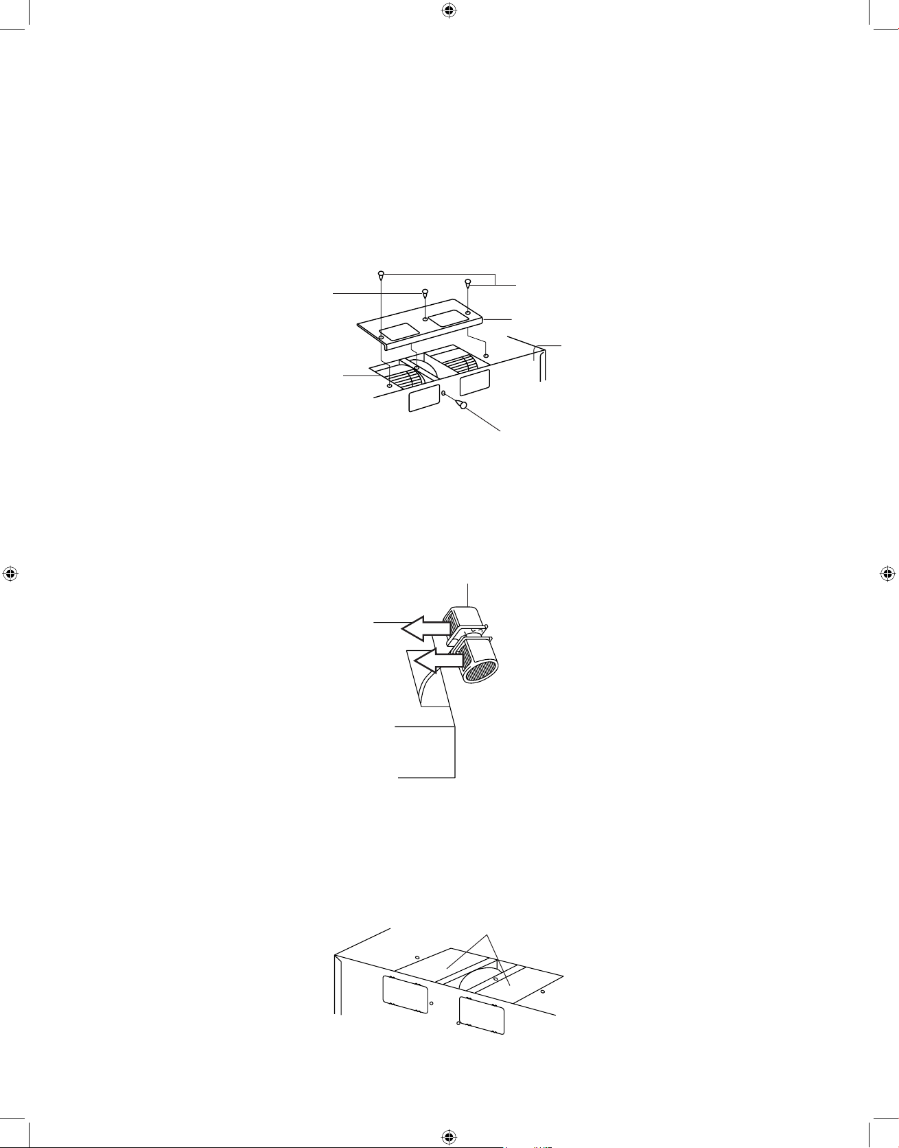
Changing the exhaust direction to the recirculating mode
(1) Remove two blower cover plate mounting screws and two blower unit mounting screws (top and rear).
(Fig. 1-2-1)
(2) Remove the blower plate from the product. (Fig. 1-2-1)
Blower Unit
Mounting Screws
Blower Unit
Blower Plate
Mounting Screws
Blower Plate
Back Plate
Blower Unit
Mounting Screws
Fig. 1-2-1
(3) Carefully lift the blower unit out of the product, and rotate blower unit 90 degrees so the exhaust ports are
facing toward the front of the product. (Fig. 1-2-2)
Blower Unit
Fig. 1-2-2
(4) Replace blower unit back into product. Be careful not to pinch the lead wires between blower unit and oven
top. Make sure the fan blades are visible through the front exhaust openings. (Fig. 1-2-3)
Flat surface of blower unit
(No exhaust shown on top)
Fig. 1-2-3
5
IP3297_F03138Q03CP_Eng_00_101028.indd 5IP3297_F03138Q03CP_Eng_00_101028.indd 5 2010-10-28 11:51:292010-10-28 11:51:29
 Loading...