

Panasonic NA1-PK3-C5 Installation Manual
INSTRUCTION MANUAL
Compact-size Picking Sensor
NA1-PK3 Series
Thank you very much for using SUNX products.
Please read this Instruction Manual carefully and
thoroughly for the correct and optimum use of this
product. Kindly keep this manual in a convenient
place for quick reference.
3
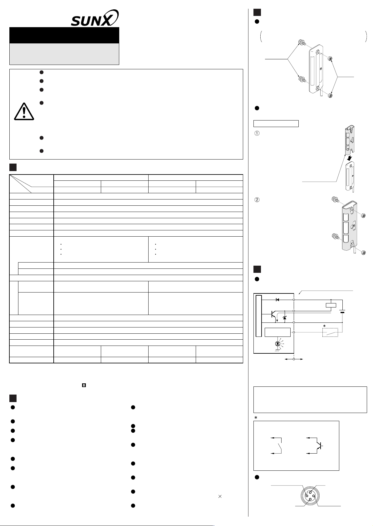
MOUNTING
Use M4 screws with washers and M4 nuts. The
tightening torque should be 0.5N·m or less.
Please arrange the screws and the nuts
separately.
M4 screws
with washers
If this product is used as a sensing device for personnel protection, serious body injury or
death could result.
Never use this product as a sensing device with any press machine, shearing machine, roll grinding
machine, forming machine, vulcanizer, or robot etc. for protection of a hand or a part of the body.
This product does not include a self-checking circuit for safety functions necessary to allow its use
as a sefety device. Thus, a system failure or malfunction can result in either an energized or a
de-energized output condition.
When this product is used as a sensing device in the following applications and if a problem relating to
‘law’ or ‘product liability’ occurs, SUNX shall not be liable for the failure and for the damage or less.
Use of this product installed to a machinery or a device as a sensing device to detect a hand or a
1)
part of the operator’s body entering a dangerous area and stop the machinery or the device.
Installation of this product to a protection device for preventing to enter a dangerous area and
2)
WARNING
1
SPECIFICATIONS
Item
Model No. (Note 1)
use of this as a sensing device which detectes a hand or a part of the operator’s body and
open/close the door or window.
Use of this product as a sensing device for personnel protection (including interlock).
3)
For sensing devices to be used as safety devices for press machines or for personnel protection,
use products which meet standards, such as OSHA, ANSI or IEC etc., for personnel protection
applicable in each region or country.
In case of using as a safety device for press machine, use a product approved by the Ministry of
Labor in Japan.
Type
2m cable length type
NPN output PNP output
5m cable length type
NA1-PK3
Sensing height
Sensing range
Beam pitch
Number of beam channels
Sensing object
Supply voltage
Current consumption
Output
NPN open-collector transistor
Maximum sink current: 100mA
Applied voltage: 30V DC or less (between output and 0V)
Residual voltage: 1V or less (at 100mA sink current)
12 to 24V DC ±10% Ripple P-P 10% or less
Emitter: 30mA or less, Receiver: 50mA or less
0.4V or less (at 16mA sink current)
Output operation
ON or OFF when one or more beam channels are interrupted, selectable by a switch
Short-circuit protection
Response time
Emitter
Power indicator: Green LED (lights up when the power is ON)
Job indicator: Orange LED (lights up when the job indicator input is LOW)
10ms or less (when interference prevention is used: 30ms or less)
Operation indicator: Red LED (lights up when the output is ON)
Receiver
Indicators
Interference prevention function
Ambient temperature
Stable incident beam indicator: Green LED:
(lights up when the all beams are stably received)
Job indicator: Orange LED (lights up when the job indicator input is LOW)
Incorporated (Up to 3 units can be closely mounted) (Note 2)
–10 to +55°C (No dew condensation or icing allowed), Storage: –20 to +70°C
Ambient humidity
Emitting element
Material
Cable
Weight
Notes: 1)
The model No. with suffix ‘-J’ is pigtailed type. (cable length: 0.3m)
Model No. NA1-PK3(-PN)-J
For the cable connected with the pigtailed type, use the connection cable CN-24-C2 (cable length: 2m)
(optional) or CN-24-C5 (cable length: 5m) (optional).
For details, please refer to ‘ INTERFERENCE PREVENTION FUNCTION’.
2)
2
CAUTIONS
Make sure to carry out the wiring and operation
of the selection switch in the power supply off
condition.
Take care that wrong wiring may damage the
sensor.
Verify that the supply voltage variation is within
the rating.
If power is supplied from a commercial switching
regulator, ensure that the frame ground (F.G.)
terminal of the power supply is connected to an
actual ground.
Do not use during the initial transient time (0.5
sec.) after the power supply is switched on.
In case noise generating equipment (switching
regulator, inverter motor, etc.) is used in the vicinity
of the sensor, connect the frame ground (F.G.)
terminal of the equipment to an actual ground.
Extension up to total 100m is possible with
0.3mm2, or more, cable for both emitter and
receiver. However, in order to reduce noise,
make the wiring as short as possible.
Do not run the wires together with high-voltage lines
or power lines or put them in the same raceway.
This can cause malfunction due to induction.
Enclosure: Heat-resistant ABS, Lens cover: Acrylic, Display cover: Acrylic
0.2mm2 4-core (emitter: 3-core)
oil resistant cabtyre cable, 2m long
Emitter: 50g approx., Receiver: 50g Emitter: 50g approx., Receiver: 50g
Infrared Red LED (synchronized scanning system)
0.2mm2 4-core (emitter: 3-core)
oil resistant cabtyre cable, 5m long
Emitter: 105g approx., Receiver: 110g Emitter: 105g approx., Receiver: 110g
2m cable length type
NA1-PK3-C5
NA1-PK3-PN
49.2mm
30 to 300mm
24.6mm
3 beam channels
ø29mm or more opaque object
PNP open-collector transistor
Maximum source current: 100mA
Applied voltage: 30V DC or less (between output and +V)
Residual voltage:
Incorporated
Power indicator: Green LED (lights up when the power is ON)
Job indicator: Orange LED (lights up when the job indicator input is HIGH)
Operation indicator: Red LED (lights up when the output is ON)
Stable incident beam indicator: Green LED:
(lights up when the all beams are stably received)
Job indicator: Orange LED (lights up when the job indicator input is HIGH)
35 to 85% RH, Storage: 35 to 85% RH
0.2mm2 4-core (emitter: 3-core)
oil resistant cabtyre cable, 2m long
Take care that the sensor is not directly exposed to
fluorescent light from a rapid-starter lamp or a high
frequency lighting device, as it may affect the
sensing performance.
Avoid dust, dirt, and steam.
Take care that the product does not come in direct
contact with water, oil, grease or organic solvents,
such as, thinner, etc.
Make sure to use an isolation transformer for the
DC power supply. If an auto-transformer (single
winding transformer) is used, this product or the
power supply may get damaged.
In case a surge is generated in the used power
supply, connect a surge absorber to the supply
and absorb the surge.
The emitter and the receiver must face each other
correctly. If they are set upside down, the sensor
does not work.
In order to turn the switches, a 'minus' screwdriver
is required. (The blade should be 2.5 0.6mm or
less)
This sensor is suitable for indoor use only.
Mounting method
5m cable length type
NA1-PK3-PN-C5
1V or less (at 100mA source current)
0.4V or less (at 16mA source current)
4
0.2mm2 4-core (emitter: 3-core)
oil resistant cabtyre cable, 5m long
Notes: 1)
Symbols...
1
Non-contact voltage or
NPN open-collector transistor
Low (0 to 2V): Lights up
High (5 to 30V, or open): Lights off
Note: No connection is required for the emitter.
M4 nuts
The sensor protection bracket (MS-NA3-3)
(optional) is also available.
Insert the sensor protection
bracket (MS-NA3-3) from
upwards of the sensor body,
and match the position of the
mounting holes of the sensor
body and the sensor protection bracket (MS-NA3-3).
Sensor protection
bracket (MS-NA3-3)
(optional)
Mount with the M4 screws
with washers and the M4 nuts
enclosed with the sensor
protection bracket (MS-NA3-3).
The tightening torque should
be 0.5N·m or less.
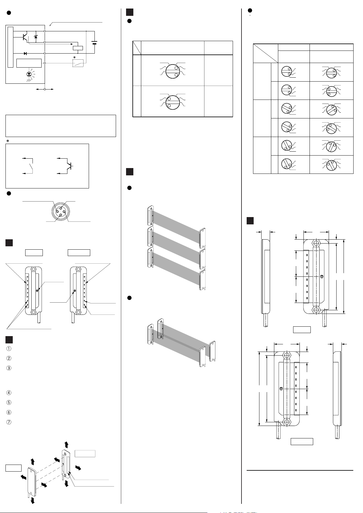
I/O CIRCUIT AND WIRING DIAGRAMS
NPN output type
D
Tr
Sensor circuit
Job indicator
lighting circuit
The output is not incorporated in the emitter.
When the job indicator is used as a large size
2)
operation indicator, connect the job indicator
input wire (pink) of the emitter and receiver to the
output wire (black) of the receiver.
D
: Reserve supply polarity protection diode
ZD
: Surge absorption zener diode
Tr
: NPN output transistor
E
: Job indicator (IND.)
Connector-pin position (Pigtailed type)
Job indicator input
Color code / Connector pin No.
of the pigtailed type
(Brown / 1)+V
(Black / 4)
Output (Note 1)
Z
D
E
100mA max.
(Blue / 3) 0V
(Pink / 2) Job
indicator input
(Note 2)
Users’ circuitInternal circuit
or
2
3
0V
Load
+
–
1
1
+V
4
Output (Note)
12 to 24V DC
±10%
PNP output type
Tr
D
Sensor circuit
Job indicator
lighting circuit
The output is not incorporated in the emitter.
Notes: 1)
When the job indicator is used as a large size
2)
operation indicator, connect the job indicator
input wire (pink) of the emitter and receiver to the
output wire (black) of the receiver.
D
Symbols...
: Reserve supply polarity protection diode
Z
D
: Surge absorption zener diode
Tr
: PNP output transistor
E
: Job indicator (IND.)
Color code / Connector pin No.
of the pigtailed type
(Brown / 1)+V
(Black / 4)
ZD
Output (Note 1)
100mA max.
(Blue / 3) 0V
(Pink / 2) Job
indicator input
(Note 2)
E
Users’ circuitInternal circuit
Load
1
1
Non-contact voltage or
PNP open-collector transistor
or
High (4 to 30V): Lights up
Low (0 to 0.6V, or open): Lights off
Connector-pin position (Pigtailed type)
2
Job indicator input
1
+V
+
–
12 to 24V DC
±
10%
7
SELECTION OF OPERATION
The output operation can be selected by the
operation/frequency selection switch on the
receiver. (Make sure to set the switch in the
power supply off condition.)
State of operation/frequency
selection switch
3
FREQ.
2
1
L-OND-ON
D-ON
3
FREQ.
2
1
D-ON
Notes: 1)
Selection of the output operation and the
frequency for the receiver is carried out with
the same switch. When the output operation is
set, be sure to select the same frequency No.
of the emitter and the receiver.
2)
In case the operation/frequency selection
switch is set to the position other than 1, 2 or
3, the state of the receiver is in
D-ON/frequency 1.
8
INTERFERENCE PREVENTION
3
2
1
3
2
1
Output operation
OFF when
FREQ.
one or more
beams are
L-ON
interrupted.
ON when
FREQ.
one or more
beams are
L-ON
interrupted.
FUNCTION
By setting different emission frequencies,
three sets of the sensors can be mounted
closely as shown in the figure below.
Frequency setting
Set the both emitting and receiving frequency
of Sensor 1 to FREQ. 1, the both emitting and
receiving frequency of Sensor 2 to FREQ. 2
and the both emitting and receiving frequency
of Sensor 3 to FREQ. 3. (Make sure to set the
switch in the power supply off condition.)
ReceiverEmitter
Frequency
selection switch
L-OND-ONL-OND-ONL-OND-ON
Sensor 1
Sensor 2
Sensor 3
Take care that selection of the output
Notes: 1)
operation and the frequency for the receiver is
carried out with the same switch.
In case the frequency switch and the
2)
operation/frequency selection switch is set to
the position other than 1, 2 or 3, the state of
the emitter is in frequency 1 and that of the
receiver is in D-ON/frequency 1.
Operation/Frequency
selection switch
FREQ.
D-ON
FREQ.
D-ON
FREQ.
D-ON
FREQ.
D-ON
FREQ.
D-ON
FREQ.
D-ON
3
2
1
3
2
1
3
2
1
3
2
1
3
2
1
3
2
1
1
2
3
1
2
3
1
2
3
1
2
3
1
2
3
1
2
3
FREQ.
FREQ.
FREQ.
FREQ.
FREQ.
FREQ.
3
2
1
3
2
1
3
2
1
3
2
1
3
2
1
3
2
1
FREQ.
L-ON
FREQ.
L-ON
FREQ.
L-ON
FREQ.
L-ON
FREQ.
L-ON
FREQ.
L-ON
3
0V
Note: No connection is required for the emitter.
Note: No connection is required for the emitter.
5
PARTS DESCRIPTION
Emitter
Frequency
selection
switch
Operation/
frequency
selection
switch
Power indicator (Green)
6
BEAM ALIGNMENT
4
Output (Note)
Receiver
Job indicator (Orange)Job indicator (Orange)
Stable incident
beam indicator
(Green)
Operation
indicator (Red)
Place the emitter and the receiver face to face
along a straight line.
After the cables have been correctly
connected, switch the power ON.
Move the emitter in the up, down, left and right
directions, in order to determine the range of the
beam received condition with the help of the
operation indicator (red) on the receiver. Then,
set the emitter at the center of this range.
Similarly, adjust for up, down, left and right
angular movement of the emitter.
Further, perform the angular adjustment for
the receiver also.
Check that the stable incident beam indicator
(green) lights up.
Interrupt each beam channel with the actual sensing
object, and confirm that the sensor operates correctly.
Note: The stable incident beam indicator (green) lights up
when all the three beams are stably received by the
receiver.
Sensor 1
Sensor 2
Sensor 3
However, if the sensors are mounted closely
as shown in the figure below, up to 2 sets of
sensors are possible.
Sensor 2
Sensor 1
9
DIMENSIONS (Unit: mm)
8
24
10.4
24.6
24.6
Emitter
3.5 24
10.4
24.6
6370
24.6
Receiver
3.5
63 70
8
Emitter
Receiver
Stable incident beam
indicator (Green)
Operation indicator (Red)
http://www.sunx.co.jp/ SUNX Limited
SUNX Limited
2431-1 Ushiyama-cho, Kasugai-shi, Aichi, 486-0901, Japan
Phone: +81-(0)568-33-7211 FAX: +81-(0)568-33-2631
Overseas Sales Dept.
Phone: +81-(0)568-33-7861 FAX: +81-(0)568-33-8591
PRINTED IN JAPAN
 Loading...