

Page 1
Order No. VES1605003CE
Drum Type Washing Machine
Model No. NA-127VB6WSR
Product Colour : White
Destination : ISRAEL
TABLE OF CONTENTS
PAGE PAGE
1 Safety Precautions----------------------------------------------- 2
2 Specifications ----------------------------------------------------- 3
3 Location of Controls and Components ------------------- 5
4 Installation Instructions---------------------------------------- 6
5 Operating Instructions------------------------------------------8
6 Test Mode ----------------------------------------------------------10
7 Service Mode -----------------------------------------------------12
8 Troubleshooting Guide----------------------------------------14
9 Critical Torque Values -----------------------------------------15
10 Disassembly and Assembly Instructions ---------------16
11 Component Specifications-----------------------------------32
12 Wiring Connection Diagram ---------------------------------40
13 Exploded View and Replacement Parts List -----------42
© Panasonic Corporation 2016 Unauthorized copying and distribution is a violation of law.
Page 2
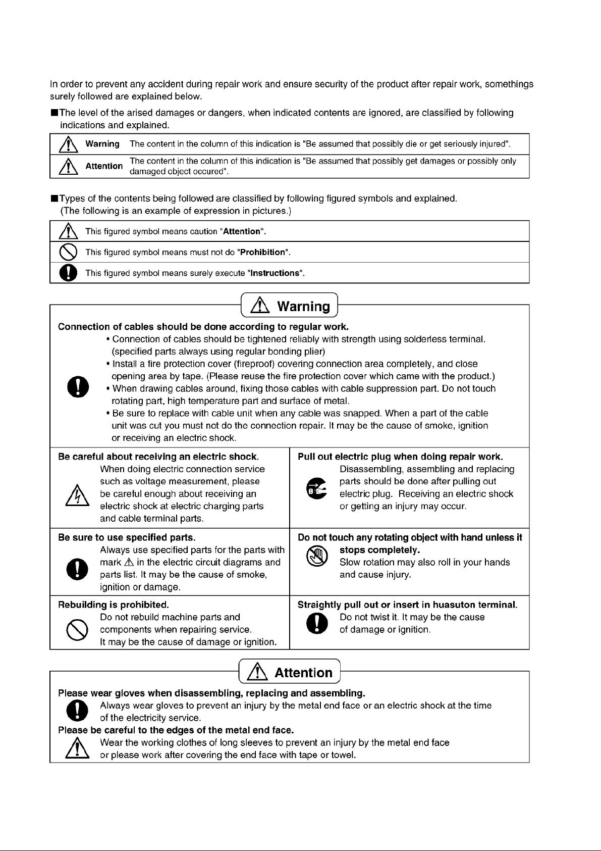
1 Safety Precautions
2
Page 3
2 Specifications
2.1. Product Specifications
Model NA-127VB6
Product Type Front Loader
Capacity 7 kg
Max Spin Speed 1200 rpm
Drum Volume 50 lt
Energy Label Rating A+++
Energy Consumption 162 kWh / annum
Water Consumption 9240 L/annum
Noise Level
Control Panel LCD Display
Wash Programs 15 settings
Spin Speed Setting 7 setting
Dimensions
Door Opening Large door opening
Delay Time Setting Yes
Colour White
Water Protection Overflow Protection
Other Features Child Lock
Packaging Shrink package
Wash 58 dBA
Spin 74 dBA
Height 84.5 cm
Width 59.7 cm
Depth 52.7 cm
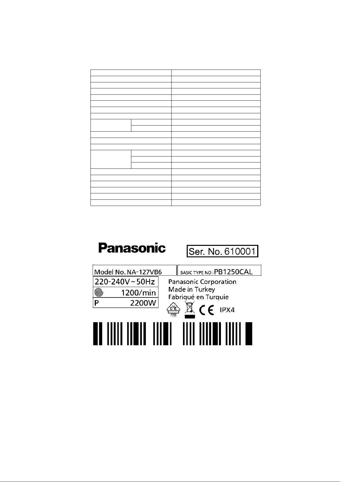
2.2. Name Plate (Example)
3
Page 4
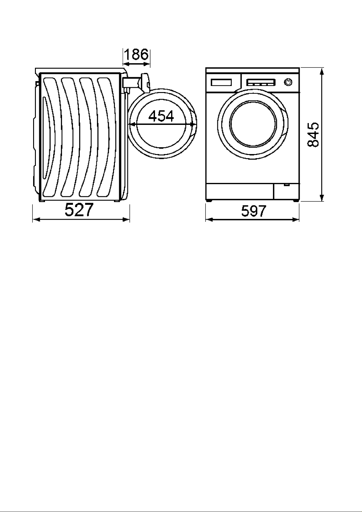
2.3. Dimension
Dimension in millimetres
NA-127VB6
4
Page 5

3 Location of Controls and Components
5
Page 6

4 Installation Instructions
4.1. Moving and Installing
4.1.1. Removal of Transportation Screw
1. Transportation screws, which are located at the back side
of the machine, must be removed before running the
machine.
2. Loosen the screws by turning them anticlockwise with a
suitable spanner.
3. Pull out the screws and rubber washers.
4.1.2. Foot Adjustment
1. Do not install machine on rugs or similar surfaces.
2. For machine to work silently and without any vibration, it
should be installed on a flat, non-slippery firm surface.
Any suspended floor must be suitably strengthened.
3. You can adjust the level of machine using its feet.
4. First, loosen the plastic adjustment nut away from the
cabinet base.
5. Change the level by adjusting the feet upwards or downwards.
6. After level has been reached, tighten the plastic adjustment nut again by rotating it upwards against the base of
the cabinet.
7. Never put cartons, wooden blocks or similar materials
under the machine to balance irregularities of the floor.
4. The holes where the transport screws have been
removed should be covered with the plastic transport
caps found in the accessories bag.
5. The transportation screws that have been removed from
the machine must be re-used in any future transporting of
the machine.
4.1.3. Electrical Connection
1. Washing machine requires a 50Hz supply of 220240Volts.
2. A special earthed plug has been attached to the supply
cord of washing machine. This plug must be fitted to an
earthed socket. The fuse value fitted to this plug should
be 13 amps. If you have any doubts about electrical supply, consult a qualified electrician.
THIS APPLIANCE MUST BE EARTHED.
Insert the machine’s plug to a grounded socket which
you can easily reach.
6
Page 7

4.1.4. Water Supply Connection
1. Washing machine is supplied with a single (cold) water
inlet.
2. To prevent leakage from the connection joints, a rubber
washer is included in the hose packing. Fit this washer at
the end of water inlet hose on the tap side.
3. Connect the hose to the water inlet valve. Tighten the
plastic connector by hand. Please call a qualified plumber
if you are unsure about this.
4. Water pressure of 0,1-1 MPa from tap will enable
machine to work more efficiently. (0,1 MPa pressure
means water flow of more than 8 litres in 1 minute from a
fully opened tap)
5. After connection is complete, check for leakage by turning
on tap completely.
6. Make sure that water inlet hoses can not become folded,
damaged, stretched or crushed when the washing
machine is in its final position.
7. Mount the water inlet hose to a
3
/4” threaded water tap.
4.1.5. Drain Connection
1. Make sure that water inlet hoses are not folded, twisted,
crushed or stretched.
2. The drain hose should be mounted at a minimum height
of 60 cm, and a maximum height of 100 cm from the floor.
3. The end of the drain hose can be connected directly to a
drainage stand-pipe or alternatively to a specific connection point designed for that purpose on the waste outlet of
a sink unit.
4. Do not extend the drain hose or guarantee will be invalidated.
4.2. Detergent Box Group
PREWASH = WATER ENTRY VALVE 1
MAIN = WATER ENTRY VALVE 2
SOFTENER = WATER ENTRY VALVE 1 + VALVE 2
7
Page 8

5 Operating Instructions
5.1. LCD Screen, Function Buttons & Knobs
PR Program selector 16 programs including off position
SW1 Switch 1, Start / Pause
SW2 Switch 2, Temperature Selection
SW3 Switch 3, Spin Speed Selection
SW4 Switch 4, Delay Timer Selection
SW5 Switch 5, Extra Rinse Option
SW6 Switch 6, Easy Ironing Option
SW7 Switch 7, Eco/Speed Mode Option
SS1 7 Segment LCD for Temperature Display I8 Extra Rinse Symbol
SS2 7 Segment LCD for Spin Speed Display I9 Easy Ironing Symbol
SS3 7 Segment LCD for Remaining Time I10 Eco Mode Symbol
I1 Child Lock Symbol I11 Speed Mode Symbol
I2 Door Lock Symbol I12 Cold Wash Symbol
I3 Drain Phase Symbol I13 Temperature Sign
I4 Spin Phase Symbol I14 Program Proceeding Zone
I5 Rinse Phase Symbol Slow Blink ON 0.5 sec, OFF 0.5 sec, ON 0.5 sec
I6 Wash Phase Symbol Fast Blink ON 0.10 sec, OFF 0.10 sec, ON 0.10 se
I7 Delay Symbol
8
Page 9
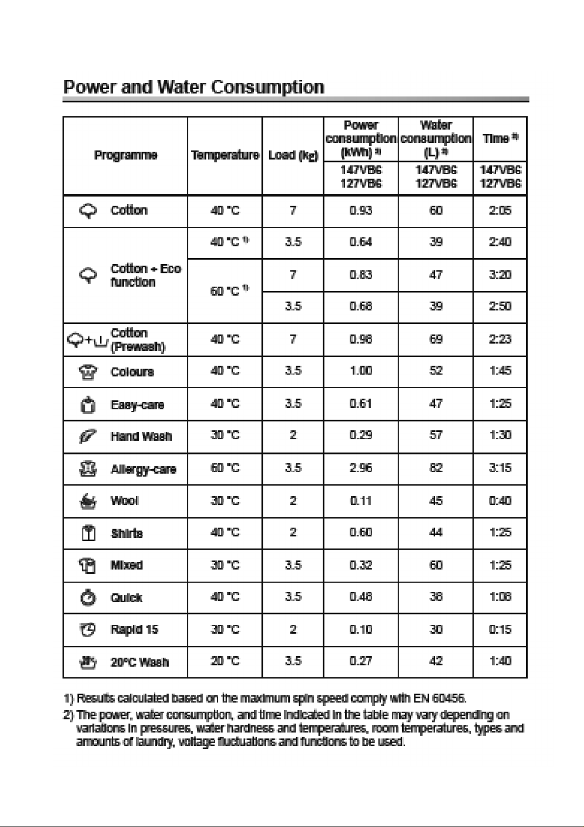
5.2. Program Details
9
Page 10

5.3. Child Lock
Activation
1. Press SW7 for 5 seconds.
2. The Child Lock Symbol on appears on the LCD display as
Child Lock is active.
6 Test Mode
Deactivation
1. Press SW7 for 5 seconds.
2. The Child Lock Symbol will disappear on LCD display
upon deactivation.
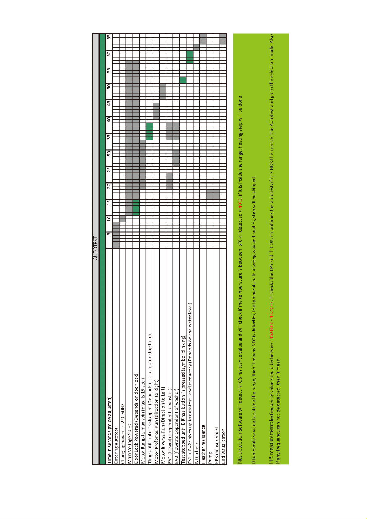
6.1. Autotest
1. Set PR to program 3 (Colours)
2. While pressing SW5 (Extra Rinse), change position of the
PR from third program to second (Cotton-Prewash), and
release SW5.
3. Autotest starts.
10
Page 11
11
Page 12
7 Service Mode
7.1. Service Autotest
1. Set PR to program 3 (Colours) and press SW2 (T°C) 2. While pressing the SW2, change PR position from third to
second, and release the SW2 button.
3. Bring PR to desired test step (1st ,2nd or 3rd program position) as soon as “SAU” is displayed on LCD.
LCD Display status:
I2 Door Lock Symbol Fixed on
SS3 SAU
Step1 Step2 Step3
PR Position:
Program 1
(Cotton)
Result Result Result
HEATER ON PUMP ON TEST PROGRAM ON
When entering in service
Comments :
test, door will be locked.
The test steps are as below ;
Step 1 :
• Selector Program 1 (Cotton) will be “HEATER ON”
• Before heating it should take water till first level frequency
then start heating.
• Heater will be on max. 8 minutes after this 8 minutes if the
temp. doesn’t change more than 2 °C then it will give NTC
failure. (E05).
• Or if the NTC connection is broken then it should give again
E05 NTC failure.
PR Position:
Program 2
(Cotton Prewash)
Door will be unlocked, machine
PR Position:
Program 3
(Colours)
(Rapid 12’)
Test is over
will go to END state.
Step 2 :
• Selector Program 2 (Cotton Prewash) will be “PUMP ON”
• Temperature will be measured, if it is higher than 5 0 °C, it
should take 60 sec. cooling water, and then make “Drain + 5
sec.”
• At the end of pump activation, “SAU” visualization should
make slow blink to indicate that the step is over.
Step 3 :
• At the end of heating, “SAU” visualization should make slow
blink to indicate that the step is over.
• Note : If user changes the selector position, machine will do
what is defined for the new selected position.
• Selector position 3 (Colours) will be a 12 mins test program
where all functions of the appliance will be checked.
• Machine will make exactly the same algorithm of Super
Rapid 12'.
So, time for selector position 3 is 12 minutes.
• At the end of test program “End” is visualized on LCD a nd
door is unlocked.
12
Page 13

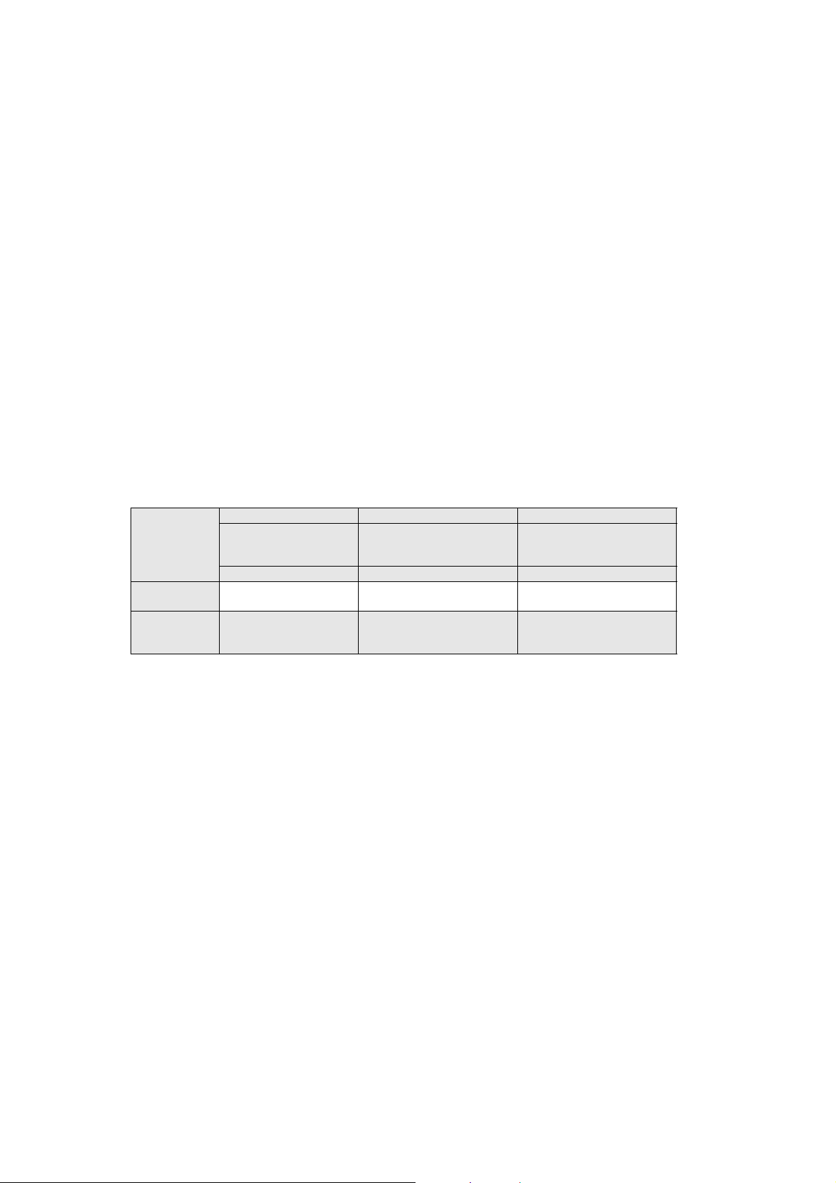
7.2. Failure Codes
Error Indication Error Number
Door is not locked E01 Yes Yes
Door is unlocked during programme E01 Yes Yes
Lack of water E02 Yes Yes
Pump failure E03 Yes Yes
Overflow E04 Yes Yes
NTC or Heater Failure E05 No Yes
Motor Failure - 1 (Tachometer open-short circuit or
motor connector is disconnected)
Motor Failure - 2 (triac short circuit) E08 No Yes
Electronic Pressure Sensor E10 No Yes
E06 No Yes
Indication For User Indication For Service
Yes/No Yes/No
13
Page 14
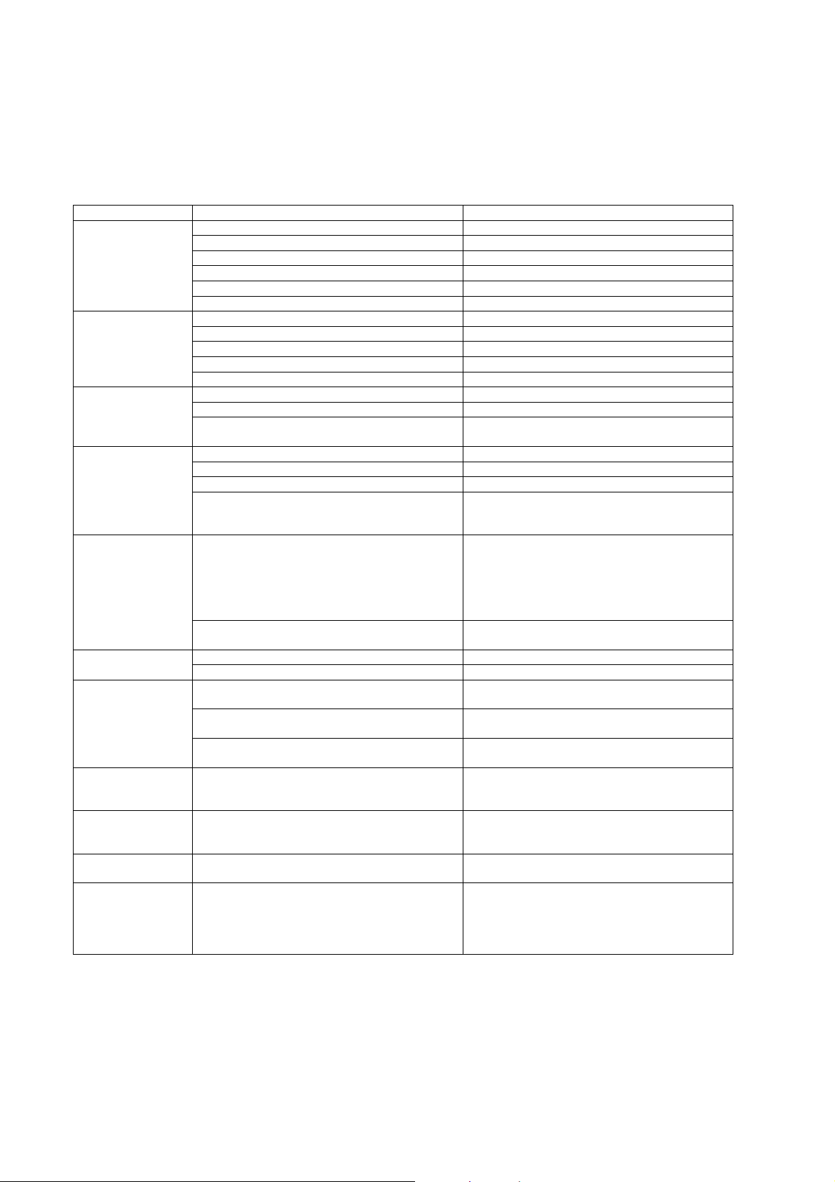
8 Troubleshooting Guide
All repairs which must be done on the machine should be done by authorized agents only. When a repair is required for machine or
you are unable to eliminate the failure with the help of the information given below:
• Unplug the machine.
• Close the water tap.
FAILURE PROBABLE CAUSE METHODS OF ELIMINATION
Machine does not
operate.
Machine does not
receive water.
Machine is not draining water.
Machine is vibrating. The feet of machine are not adjusted. Adjust the feet.
Excessive foam in
the detergent drawer.
The washing result is
bad.
The washing result is
not good.
The water is seen in
the drum during
washing.
There are residues of
detergent on the
clothes.
There are grey stains
on the clothes.
The spinning process
is not done or starts
with delay.
It is unplugged. Insert the plug into the socket.
Fuse is defective. Change fuse.
Start / Pause button has not been pressed. Press the start / pause button.
The program knob is in 0 (off) status. Bring the program knob on the desired status.
The door is not shut properly. Shut the door properly. You should hear the click.
Child lock is active. See section 5.3.
Water tap is closed. Open water tap.
The water inlet hose may be bent. Check the water inlet hose.
The water inlet hose is obstructed. Clean the filters of water inlet hose.
The water inlet filter is obstructed. Clean the valve inlet filters.
The door is not shut properly. Shut the door properly. You should hear the click.
The drain hose is obstructed or bent. Check the drain hose.
The pump filter is obstructed. Clean the pump filter.
The clothes are not placed inside the machine in a
well-balanced manner.
Transportation screws are not removed. Remove transportation screws.
There is a small amount of clothes in the device. It does not prevent operation of the machine.
Excessive amount of clothes are filled in the machine
or the clothes are not placed in a well-balanced manner.
Too much detergent has been used. Press the start/pause button. In order to stop the
Wrong detergent has been used. Use only the detergents produced for full automatic
Laundry too dirty for the program you have selected. Select a suitable program.
The amount of detergent used is not sufficient. Use more detergent according to the detergent.
Clothes exceeding the maximum capacity has been
filled in machine.
Water may be hard. Use the amount of detergent according to the declara-
Distribution of the clothes in machine is not well-balanced.
No failure. The water is at the lower part of the drum.
The pieces of some detergents which do not dissolve
in water may stick to clothes as white stains.
These stains may be caused by oil, cream or ointment.
No failure. The unbalanced load control works in that
way.
Spread the clothes inside the machine in an orderly
and well-balanced manner.
Do not exceed the recommended quantity of clothes
and spared clothes in the machine in a well-balanced
manner.
foam, dilute one table-spoon of softener in half liter of
water and pour it in the detergent drawer. Press the
start/pause button after 5-10 minutes. Arrange the
amount of the detergent properly in the next washing
process.
machines.
Put the clothes in machine in a manner not to exceed
its maximum capacity.
tion of the detergent producer.
Spread the clothes inside the machine in an orderly
and well-balanced manner.
By calibrating machine for “Rinsing” program, make
an additional rinsing or eliminate the stains After drying with the help of a brush.
In the next washing operation, use the maximum
detergent amount declared by the detergent producer.
The unbalanced load control system will try to distribute clothes in a homogenous manner. After clothes
are distributed, passage to spinning process will be
realized. In the next washing process, place clothes
into the machine in a well-balanced manner.
14
Page 15

9 Critical Torque Values
ASSEMBLY LOCATION BOLT/NUT TORQUE
MIN. (Nm)
* Transport Screw Assembly Transport Screws 6.50 6.50 7.00 1000
* Motor Assembly Motor Screws 6.00 6.50 7.50 800
* Front Concrete Weight - Front
Tub Assembly
* Upper Counter Weight Assembly Upper Counter Weight Screws 25.00 27.50 30.00 440
* Pulley - Drive Shaft - Washing
Group Assembly
* Heater Assembly Heater Assembly Nut 3.85 4.00 4.00 970
Front Counterweight Screws 14.00 14.50 14.75 600
Pulley – Drive Shaft Assembly Bolt 39.50 40.00 40.50 440
TORQUE
NOM. (Nm)
TORQUE
MAX. (Nm)
Air Pressure
Wrench (rpm)
The bolts/nuts above are important for product safety purposes. Please tighten screw, bolt s and nut s according to the torque values
given in table above.
15
Page 16

10 Disassembly and Assembly Instructions
10.1. Top Plate
1. Remove two screws that fix the top-plate at the back.
2. Push the top-plate back and pull it up.
10.2. Door
1. Remove two screws that fix the door. (by using T25 tool)
2. Pull the door up.
16
Page 17

3. Remove screws that fix the door group.
6. Remove six screws that fix the door hinge.
4. Put the door outside plastic with helping screwdriver.
5. Remove the door inside plastic.
7. Remove the door handle.
8. Remove the door handle pin.
17
Page 18

10.3. Spring Wire
1. First remove the spring wire fixing the tub bellows seal by
using the small size screwdriver.
Pull the tub bellows seal.
2. Remove the tub bellows seal-body fixing sprin g .
10.4. Detergent Drawer
1. Gently pull the detergent drawer.
2. While pressing siphon cover keep pulling drawer to
remove it.
18
Page 19

10.5. Control Panel
1. Remove the screw which fixes the control panel to the
front panel.
2. Remove two screws fixing control panel.
10.6. Electronic Card
1. Depress the taps fixing the card by using a screwdriver.
2. Release the socket fixing plastic by depressing the taps
with the help of a screwdriver.
3. Pull the control panel out.
3. Remove the card out off panel.
4. Remove the sockets on the card.
19
Page 20

5. After releasing sockets, remove PCB box from its housing
around the box.
9. Remove the card from its housing and unplug its connector.
6. Disassemble the PCD box and its cover.
7. Remove the PCB card by depressing the taps that fix it.
10. Remove the LCD screen by depressing the taps by using
a screwdriver.
8. Remove the connector that fix the LCD screen.
20
Page 21

10.7. Front Panel
1. Remove the screw fixing the front panel at the bottom.
2. Remove two screws fixing the door lock.
4. Remove the tub bellows seal.
5. Remove two screws fixing front panel to body.
6. Pull front panel up.
3.
7. Remove front panel.
21
Page 22

10.8. Support Bracket
1. Remove two clips fixing detergent drawer housing to
upper support bracket..
10.9. Detergent Drawer Housing
1. Remove the tub bellow hose by releasing the holder
extensions of bellow hose.
2. Unplug connectors from feed valve.
3. Slightly turn the feed valve counter-clockwise to remove.
4. Remove the detergent drawer housing assembly.
22
Page 23

10.10. Power Cable Group and EMI Filter
1. Remove the five connectors that is connected to the EMI
filter.
2. Remove two screws fixing the EMI filter.
4. Remove EMI filter.
3. Pull the power cable group up.
23
Page 24

10.11. Electronic Pressure Switch (EPS)
1. Unplug EPS connector.
10.12. Door Lock
1. Unplug door lock connector.
2. Pull EPS up.
3. Remove clamp from EPS hose.
10.13. Drain Pump
1. Remove clamp holding drain hose by using a plier.
2. Remove clamp fixing tub outlet hose.
24
Page 25

3. Unplug drain pump connector.
4. Remove screws holding drain pump.
10.14. Front Counterweight
1. Remove three screws on the front counterweight.
(Wrench size 13 mm)
2. Gently pull counterweight out.
25
Page 26

10.15. Heater
1. Unplug heater connectors.
2. Remove nut (8 mm) fixing the heater.
10.16. Twinjet System
1. Remove twinjet hoses from tub bellow seal pulling them
up.
2. Remove screw fixing circulation pump.
3. Pull heater out gently holding both sides.
3. Lay the appliance down and press on ratchet holding circulation pump.
26
Page 27

4. Remove circulation pump.
5. Remove cable connector.
10.17. Tub Bellow Seal
1. Remove the tub gasket clip by using small screwdriver.
2. Hold the tub bellows seal and gasket-body fixing spring
together, and pull them out.
6. Remove hose connecting circulation pump to drain pump.
27
Page 28

10.18. Transport Screw
1. Remove four transport screws.
2. Hold the transport screw and pull it out.
10.19. Upper Counterweight
1. Remove two screws fixing the upper counterweight by
using box wrench size 13 mm.
2. Hold and carry upper-counterweight out.
28
Page 29

10.20. Washing Group
1. Unplug motor connectors.
4. Remove the washing group carrying it out through front
side.
2. Cut all the cable ties which fix cable group.
3. Remove the screws fixing hanger bracket.
10.21. Shock Absorber Pin
1. Remove shock absorber pins squeezing the ratchet by a
pliers.
29
Page 30

10.22. Belt
1. Remove the belt rotating the driven pulley.
10.23. Driven Pulley
1. Remove the bolt at the center of pulley by tucking a
wooden bar avoids rotation.
10.24. Motor
1. Remove two screws holding motor by using box wrench.
2. Pull motor up.
2. Remove pulley.
30
Page 31

10.25. Tub
1. Remove tub inlet bellow hose loosening the clamp
squeezing it by using a pliers.
2. Remove screw holding EPS reservoir.
4. Remove 19 screws around tub using box wrench size 8
mm.
5. Remove front tub.
3. Remove tub outlet bellowed hose loosening screwedclamp.
6. Remove drum.
31
Page 32

11 Component Specifications
11.1. Drain Pump
Drain pump is both a mechanical and electrical component
which is used to drain water inside the washing machine. It
has an synchronous motor inside. For better performance
maintenance, pump filter should be cleaned regularly.
Technical features
Nominal voltage 220-240 V
Nominal current 0.28 A(±10 %)
Nominal power 37 W
Frequency 50 Hz
Testing component
Check the resistance value on the component with multimeter as shown below.
Resistance value should be between 131 - 141
Resistor (coil) 136 (±5%)
Water flow 17 L/min (to 1 m height)
Thermal protector YES
Y ou can determine the ohm value of drain pump by measuring from the socket with two blue cables connected to the electronic
card as shown in the figure.(referring X10 on the wiring diagram)
Component test
32
Page 33

11.2. Heater
Heating element (Resistance) is a component which is
designed to regulate temperature of water inside the drum.
It has three connections: Phase, neutral and ground connections.
Heater type Tubular heating element with NTC-sensor
Nominal voltage 230 V
Technical features
Nominal power 2000 W (±5%)
Resistance 26.4 ±5%
Thermal fuse 2 sided
Testing component
Check the resistance value on the component with multimeter as shown below.
Resistance value should be between 26.4 ±5%
You can determine the ohm value of resistance by measuring from the socket with grey and brown cables
(referring to X6 on the electronic card).
Component test
33
Page 34

11.3. NTC
Component which sends signals to PCB about the water
temperature inside the tub. The Resistance (Ohm) value of
the NTC decreases as the temperature increases.
Technical features
Testing component
Check the resistance value on the component with multimeter as shown below.
You can determine the ohm value by measuring from the socket with two black cables (referring to X7 on the wiring diagram).
NTC resistance value varies depending on temperature.
Component test
34
Page 35

11.4. Valve
Valve is an electrical and mechanical component which is
designed to take water from the network system into the
washining machine. It is operated by PCB card.
Nominal voltage 220-240 V
Nominal power 8 VA
Frequency 50-60 Hz
Check the resistance value on the component with multimeter as shown below. Valve water flow rate should be between
Technical features
Rated flow 7 L/min (±15 %)
Operating water pressure 0.03 - 1 Mpa
Testing component
6 - 8 L/min. Each valve coil resistance values should be between 3.3 - 4.2 k
You can determine the resistance value of the main wash valve by measuring from the large socket which has one blue, one
black and two white cables as shown in the figure below (refers X5 on the wiring diagram). Each valve coil resistance values
should be between 3.3 - 4.2 kohm.
Component test
35
Page 36

11.5. Electronic Pressure Sensor (EPS)
Electromagnetic field occurs due to movement of pressurized membrane. The spring moves vertically by nucleus
due to electromagnetic field. The water level is regulated
according to the frequency changes of the spring by electronic card.
Testing component
Push the door lock slider with screwdriver.
Select the 1st program and start the machine.
Unplug power cable when as soon as water intake finishes
and drum begins to rotate.
Check the water level inside the drum with ruler. It should
be 10 cm ±1.
36
Page 37

11.6. Motor
The washing machine has an asynchronous motor. It is
controlled by the PCB. It is essential to check the motor for
correct diagnosis and quick servicing. In the below picture,
socket points on the motor is shown to measure with multimeter.
Motor socket terminals
Testing components
Tacho resistance control
Check the motor tacho terminals on the motor socket with
multimeter as shown in the picture above.
You can determine the ohm value by measuring from pink
and red cables on the large socket as shown in the figure
(referring X2 on the wiring diagram)
Stator Resistance Control
Check the motor stator terminals on the motor socket with
multimeter as shown in the picture.
Y ou can determine the ohm value by measuring from black
and brown cables on the large (referring X2 on as shown in
right figure. For resistance values, refer to the table below.
Tacho and stator resistance values of motor:
37
Page 38

11.7. Door Lock
Door lock is activated at the beginning of the program in
order to prevent the door from opening. Locking is generated by supplying power to PTC-bimetal, after max 6sec
(220V), the bimetal will be warm and ready to close the
contacts. Thus the first impulse to the solenoid will allow
the contact to close and consequently the slider will be
locked by the pin of the sliderlock. The second impulse
causes no electrical and mechanical modifications. It can
be unlocked by the third impulse; the contact is opened
even if the PTC-bimetal remains energized.
Emergency Opening System (PTC-Bimetal) In
Case of Lack of Electric Energy
• In case of lack of electric energy during a washing cycle, the
PTC-bimetal assembly will cool down and after minimum 60
sec (considering previous power supply of 30 sec min and
T=20 °C) the door will be unlocked and thus can be opened.
• In case the door is closed when current comes back, the
PTC-bimetal assembly will heat again, the slider lock will
lock, the contact will close and the program will continue
from where it stopped.
Nominal voltage 250 V
Check the resistance value on the component with multi-meter as shown in below figures. Resistance value on the (PTC over-
load + solenoid) should be 240 ±20% at 25 °C. That resistance value can be measured from terminal 3-4 (refer to section12
Technical features
Testing component
Wiring Connection Diagram).
You can determine the ohm value of PTC by measuring from cables those are shown in the figure below as 3 and 4. (Referring
X3 on the wiring diagram).
Component test
38
Page 39

11.8. Circulation Pump
The component is used for circulation of water inside the
drum in order to increase washing performance.
Check the resistance value on the component with multimeter as shown below.
Technical features
Nominal voltage 220-240 V
Frequency 50 Hz
Resistor (coil) 169,5 (±5%)
Testing component
Resistance value should be between 160 - 180
You can determine the ohm value by measuring from the red cable at 5th and red cable at 12th position in the small socket
(refer wiring diagram in section 12) as shown below figure. Resistance value should be between 160 - 180
Component test
39
Page 40

12 Wiring Connection Diagram
12.1. Wiring Diagram (Board)
40
Page 41

12.2. Wiring Diagram (Socket)
41
Page 42

13 Exploded View and Replacement Parts List
13.1. Control Panel Parts
13.1.1. Exploded View Control Panel Parts
13.1.2. Control Panel Spare Parts
(U) : Indicates parts at the remarks that can be replaced by user.
: Components identified with have special characteristics important for safety. When replacing any of these components use
only manufacture’s specified parts.
Safety Ref. No. Part Name & Description Parts No. Qty Remarks
400 DETERGENT DRAWER COVER AXWDV-151182 1
401 CONTROL PANEL AXWCV-151181 1
403 PROGRAM ADJUSTMENT SHAFT AXWSH-069325 1
411 PCB BOX AXWPB-128166 1
412 ELECTRONIC CARD GR. AXW24V-64708 1
413 PCB BOX REAR COVER AXW2CF-91225 1
415 TOUCH BUTTONS AXW146-19208 1
420 FL CARD GROUP AXW146-57870 1
424 LCD FRAME AXWLF-134899 1
429 PR. ADJ. KNOB GR AXWSH-132581 1
1108 SOCKET HOLDER AXWSH-132583 1
42
Page 43

13.2. Front Panel Spare Parts
13.2.1. Exploded View Front Panel Spare Parts
13.2.2. Front Panel Spare Parts List
Safety Ref. No. Part Name & Description Parts No. Qty Remarks
1 BODY GROUP PAINTED AXW1AB-13489 1
2 UPPER TRAY GROUP AXW11N-16356 1
3 FRONT PANEL GROUP AXW1BB-27924 1
5 ADJUSTABLE FEET GR. AXW31-00778 4
9 HOUSING FRAME BELLOW CLIP-PHYTON AXW1Z-023407 1
10 DOOR LOCK AXW1619-4463 1
701 PUMP COVER HOUSING AXW130-05807 1
702 PUMP COVER AXW140-67962 1
1200 HINGE SUPPORT SHEET AXWHSS-19456 1
1201 FRONT PANEL GROUP (3+1200) AXW1BB-54562 1
1602 DRAIN HOSE SPONGE AXW1DH-12749 1
43
Page 44

13.3. Washing Group Spare Parts
13.3.1. Exploded View Washing Group Spare Parts
44
Page 45

13.3.2. Washing Group Spare Parts List
Safety Ref. No. Part Name & Description Parts No. Qty Remarks
103 REAR TUB GROUP AXW12A-90585 1
117 FRONT TUB AXW32G-59330 1
160 DRUM GROUP AXW22B-13458 1
102 MOTOR AXW401-13066 1
113 TUB SEAL AXW212-15077 1
101 DRIVEN PULLEY AXW502-00499 1
100 BELT AXW412-25178 1
122 COUNTERSUNK HEAD BOLT 8X28 TORX AXWSS1-07899 4
206 TUB ENTERANCE WITH BELLOW HOSE AXWEBH-87110 1
118 TUB BELLOWS SEAL AXW212-25995 1
126 HEXAGON HEAD BOLT 6X30 PT AXWSS3-14521 19
900 HEXAGON HEAD BOLT 10 X 52 AXWSB1-23804 4
241 PLAIN WASHER 10.5X40X2.5 AXW420-08965 4
810 PLAIN WASHER (SAFETY) AXWSW1-06960 4
105 SHOCK ABSORBER PIN-2 AXWSAP-25094 4
119 TUB GASKET CLIP AXW212-08555 1
120 FRONT CONCRETE WEIGHT AXW1231-9244 1
121 RESISTANCE GR AXWRG1-96002 1
999 NTC AXW1EV-35970 1
899 RESISTANCE WITHOUT NTC AXWRG1-16814 1
115 RESISTANCE FIXING WIRE AXWRFW-18738 1
104 SHOCK ABSORBER AXWSA1-11586 1
213 TUB EXIT BELLOWS GR(HOSE+BALL) AXW1250-7585 1
124 COUNTERSUNK HEAD BOLT M 8X29 AXWSB2-05142 1
700 TUB HANGER SPRING PART AXWTHS-19298 2
221 HANGER SPRING SHEETIRON PLS. AXW1HS-16727 2
800 TUB SPRING AXW3441-5307 2
808 MUSHROOM HEAD SQUARE NECK BOLT M 8X65 AXWSB3-03063 2
806 PLAIN WASHER 8.4X28X3 AXWSW2-07454 2
811 UPPER CRT SUPPORT SHEETIRON PART AXWUCS-16379 2
812 HEX.NUT WITH FLANGE SERRATED M8 AXWXNF-00615 2
813 PLASTIC LIFTER AXW1PL-55352 3
112 UPPER CONCRETE WEIGHT AXW1231-3323 1
816 RESISTANCE PROTECTION FOIL-1-C AXW1PF-07557 1
817 SCREW 35X7PAN HEAD WITH COLAR CROSS RE. AXWSS4-15637 2
45
Page 46

13.4. Detergent Drawer Group Spare Parts
13.4.1. Exploded View Detergent Drawer Group Spare Parts
13.4.2. Detergent Drawer Group Spare Parts List
Safety Ref. No. Part Name & Description Parts No. Qty Remarks
200 DETERGENT DRAWER AXW1V-065303 1
202 SIPHON COVER AXW1PV-65308 1
214 DETERGENT DRAWER LOC. PART-BLUE AXW1DD-65309 1
203 WATER DISTRIBUTION PLATE GR AXW1WD-65322 1
205 DETERGENT DRAWER HOUSING AXW1DD-65304 1
228 PLASTIC HOSE CLAMP AXW1PH-04189 4
207 VALVE-DETERGENT BOX HOSE AXW1VD-04536 1 220mm
208 VALVE-DETERGENT BOX HOSE AXW1VD-04535 1 240mm
209 VALVE(TWO EXIT) AXW1VT-13042 1
270 DETERGENT BOX GROUP AXW21D-65326 1
275 DETERGENT BOX GROUP/HOSE AXW31D-65329 1
280 DETERGENT BOX GROUP/FULL AXW41D-10164 1
996 LIQUID DETERGENT LEVEL PLATE AXW51D-65310 1
46
Page 47

13.5. Pressure Switch Hose Group Spare Parts
13.5.1. Exploded View Pressure Switch Hose Group Spare Parts
13.5.2. Pressure Switch Hose Group Spare Parts List
Safety Ref. No. Part Name & Description Parts No. Qty Remarks
211 PRESSURE SWITCH HOSE (EPDM) AXW1PS-78599 1
212 PRESSURE SWITCH WATER RESERVOIR AXW1PS-88879 1
213 TUB EXIT BELLOWS GR(HOSE+BALL) AXW1250-7585 1
234
HOSE CLAMP Φ32.7
244
HOSE CLAMP Φ9.6
295 PRESSURE SWITCH HOSE GR.PYTHON
BALL SYST
AXW1HC-07366 1
AXW1HC-08991 1
AXW2PS-79698 1
47
Page 48

13.6. Body Group Spare Parts
13.6.1. Exploded View Body Group Spare Parts
48
Page 49

13.6.2. Body Group Spare Parts List
Safety Ref. No. Part Name & Description Parts No. Qty Remarks
20 WATER ENTRY HOSE GROUP AXW12C-14423 1
24 UPPER SUPPORT BRAKET AXW1US-96100 1
285 PUMP GROUP AXW8FT-06391 1
220 DRAIN HOSE ROUTER PLASTIC AXW1DH-19322 1
219 DRAIN HOSE AXW1DH-74837 1
225 ELECTRONIC PRESSURE SENSOR AXW1EP-06187 1
215 EMI FILTER AXW2EF-15002 1
296 CABLE GR AXW2CB-26678 1
249 CABLE HARNESS AXW14B-26679 1
250 CABLE HARNESS HOLDER PLS AXW1CH-93407 1
251 CABLE HARNESS HOLDER PLS AXW1CH-28367 1
331 LOCKING WIRE SADDLE (BLUE) AXW1CH-85086 1
895 SPRING HANGER SHEETIRON GR AXW1SH-37953 1
231 SPRING HANGER BRACKET AXW2SH-79359 1
221 HANGER SPRING SHEETIRON PLS. AXW1HS-16727 2
700 TUB HANGER SPRING PART AXWTHS-19298 2
235 DRAIN HOSE HOLDING PLS AXW1HC-14270 4
239 POWER CORD GROUP AXW4A-26588 1
222 PRESSURE SWITCH MOUNTING CLIP AXW1HC-22768 1
238 SPEED CONTROL HOLE STOPPER AXW1SC-06161 1
290 TRANSPORT SCREW GROUP-II AXW2TS-15676 4
242 TRANSPORT SCREW PLASTIC-A-II AXW1TS-18528 4
243 TRANSPORT SCREW PLASTIC-B-II AXW1TS-60789 4
240 TRANSPORT SCREW AXWSB4-08363 4
245 TRANSPORT SCREW EPDM AXW1TS-60790 4
241 PLAIN WASHER 830X29X2 AXWSW1-15272 4
132 CABLE TIE(YKB150) AXWCT-075920 7
918 DRAIN FILTER AXWDF-120197 1
919
HOSE CLAMP Φ8.6
920 FRONT PANEL DROP FIXING PLASTIC-II AXW1TP-20456 4
1404
HORT. KLPC.Φ350
1503 ST 42X95 PAN HEAD W.COL. T.UNDER. SER. EA AXWSS7-16042 2
1504 ISO 7049 ST 42X13 TORX AXWSS6-14453 4
1505 ST 42X95 TRTSB AXWSS5-14454 4
AXWHC-003440 1
AXWHC-006977 1
49
Page 50

13.7. Porthole Group Spare Parts
13.7.1. Exploded View Porthole Group Spare Parts
13.7.2. Porthole Group Spare Parts List
Safety Ref. No. Part Name & Description Parts No. Qty Remarks
6 OUTER DOOR PLASTIC AXW1DP-93322 1
7 DOOR GLASS AXW1GD-03771 1
8 INNER DOOR PLASTIC AXW1DP-86999 1
12 HINGE II-M5 AXW192-15559 1
13 HINGE BUSHING II AXW192-23907 4
14 DOOR HANDLE AXW1DH-04266 1
15 HOOK SPRING AXW1HS-07443 1
16 HANDLE SPRING AXW1HS-14985 1
17 DOOR HOOK II.(METAL) AXW1DH-08931 1
27 DOOR HANDLE TONGUE PIN AXW1DH-07434 3
28 SCREW 3.5X16PAN.HE.WITH COL.CR.RE.UN.HE. AXWSS7-08715 9
29 OUTER DOOR PLS INSERT PART AXW1DS-06270 1
32 OUTER DOOR PLS. INNER FRAME AXW1DS-80609 1
33 DOOR HINGE SUPPORT SHEET AXW192-08152 1
50 PORTHOLE GROUP AXW2DP-32501 1
410 SCREW 4X12 PAN HEAD WITH COLLAR UNDER HE AXWSB9-16360 6
1502 SCREW M5X8 TSB AXWSST-15092 2
50
Page 51

13.8. CIRCULATION GROUP
13.8.1. Exploded View of Circulation Pump Spare Parts
13.8.2. Circulation Pump Spare Parts List
Safety Ref. No. Part Name & Description Parts No. Qty Remarks
118 TUB BELLOWS SEAL AXW212-25995 1
285 PUMP GROUP(FILTER)(THER. PROTECT.) AXW8FT-06391 1
410 SCREW 4X14 PAN HEAD TYPE 2 AXWSB8-16360 1
446 ISO 7049 ST 42x13 TYPE 2 AXWSS2-08716 1
921 TWIN JET HORN/LEFT AXWTJH-25993 1
922 TWIN JET HORN/RIGHT AXWTJH-25992 1
923 TWIN JET T-ELBOW AXWTJT-25561 1
924 HANDCUFFS ?20.2 AXW2HC-08653 3
925 TWIN JET NOZZLE AXWTJN-25574 2
926 CIRCULATION PUMP AXW8CP-08568 1
927 TWIN JET CABLE HOSE HOLDER PLASTIC AXWTJC-25867 5
928
HANDCUFFS Φ26.8
929 PUMP PROTECTION FOIL-3 AXW1PF-10025 1
930 TWIN JET HOSE_N NO:1 AXWTJH-25194 1
931 TWIN JET HOSE_H NO:2 AXWTJH-31321 1
932
HANDCUFFS Φ15.88
933 PYTHON-CIRCULATION TUB GASKET GR AXWTJH-31321 1
934 TWIN _JET HOSE GROUP AXWTJH-34816 1
AXW2HC-09578 1
AXW2HC-08652 4
51
Page 52

13.9. Accessories
13.9.1. Accessories
13.9.2. Accessories Spare Parts List
Safety Ref. No. Part Name & Description Parts No. Qty Remarks
994 USER'S MANUEL AXW4F-157593 1
992 SERVICE LIST AXW9911-9390 1
995 ENERGY LABEL AXW90EL-8560 1
996 LIQUID DETERGENT LEVEL PLATE AXW51D-65310 1
997 DRAIN HOSE COAT RACK AXW90HC-0601 1
998 TRANSPORT SCREW STOPPER AXW1TS-16405 4
52
Page 53

13.10. Packaging Group Spare Parts
13.10.1. Exploded View of Packaging Group Spare Parts
53
Page 54

13.10.2. Package Group Spare Parts List
Safety Ref. No. Part Name & Description Parts No. Qty Remarks
900 BOTTOM STYROFOAM AXWPV-154370 1
901 TOP CARTON AXWPV-152496 1
902 REAR STYROFOAM(LEFT) AXWPV-277830 1
903 REAR STYROFOAM(RIGHT) AXWPV-277820 1
904 FRONT STYROFOAM LEFT AXWPV-277810 1
905 FRONT STYROFOAM RIGHT AXWPV-280760 1
906 CORNER CARDBOARD AXWPV-002040 1
907 TUB SUPPORT STYROFOAM AXWPV-053000 1
909 PACKAGE CARTON AXWPV-160507 1
54
 Loading...