

Panasonic NA-127VB5WFR, NA-127VB5WGB, NA-127VB5WTA, NA-127VB5WPL, NA-127VB5WGN Service Manual
...
© Panasonic Corporation 2013 Unauthorized copying and distribution is a violation of law.
Order No. VES1309006CE
Drum Type Washing Machine
Model No. NA-127VB5WGB
Model No. NA-127VB5WFR
Model No. NA-127VB5WES
Model No. NA-127VB5WTA
Model No. NA-127VB5WPL
Model No. NA-127VB5WGN
Model No. NA-127VB5WNR
Model No. NA-147VB5WDE
Model No. NA-147VB5WGB
Model No. NA-147VB5WGN
Model No. NA-147VB5WNR
Product Colour
White
Destination
Germany , UK, France, Belgium, Norway ,
Italy, Spain, Hungary, Holland, Poland,
Sweden, Denmark, Finland

NA-127VB5WGB / 127VB5WFR / 127VB5WES / 127VB5WTA / 127VB5WPL / 127VB5WGN / 127VB5WNR /
147VB5WDE / 147VB5WGB / 147VB5WGN / 147VB5WNR
2
TABLE OF CONTENTS
PAGE PAGE
1 Safety Precautions -----------------------------------------------3
2 Specifications------------------------------------------------------4
3 Location of Controls and Components--------------------6
4 Installation Instru ctions-----------------------------------------7
5 Operating Instructions------------------------------------------9
6 Test Mode----------------------------------------------------------11
7 Service Mode-----------------------------------------------------13
8 Troubleshooting Guide----------------------------------------14
9 Critical Torque Valuess ---------------------------------------16
10 Disassembly and Assembly Instructions---------------17
11 Component Specifications-----------------------------------28
12 Wiring Connection Diagram---------------------------------37
13 Exploded View and Replacement Parts List-----------39

NA-127VB5WGB / 127VB5WFR / 127VB5WES / 127VB5WTA / 127VB5WPL / 127VB5WGN / 127VB5WNR /
147VB5WDE / 147VB5WGB / 147VB5WGN / 147VB5WNR
3
1 Safety Precautions

NA-127VB5WGB / 127VB5WFR / 127VB5WES / 127VB5WTA / 127VB5WPL / 127VB5WGN / 127VB5WNR /
147VB5WDE / 147VB5WGB / 147VB5WGN / 147VB5WNR
4
2 Specifications
2.1. Product Specifications
2.2. Name Plate
Model NA-127VB5 NA-147VB5
Product Type Front Loader Front Loader
Capacity 7 kg 7 kg
Max Spin Speed 1200 rpm 1400 rpm
Drum Volume 50 lt 50 lt
Energy Label Rating A+++ A+++
Energy Consumption 162 kWh / annum 162 kWh / annum
Water Consumption 9240 L / annum 9240 L / annum
Noise Level
Wash 58 dBA 58 dBA
Spin 74 dBA 76 dBA
Control Panel LCD Display LCD Display
Wash Programs 15 settings 15 settings
Spin Speed Setting 6 setting 7 setting
Dimensions
Height 84.5 cm 84.5 cm
Width 59.7 cm 59.7 cm
Depth 54.2 cm 54.2 cm
Door Opening Large door opening Large door opening
Delay Time Setting Yes Yes
Colour White White
Water Protection Overflow Protection
Overflow Protection
Aquastop Hose(for Germany only)
Other Features Child Lock Child Lock
Packaging Shrink package Shrink package

NA-127VB5WGB / 127VB5WFR / 127VB5WES / 127VB5WTA / 127VB5WPL / 127VB5WGN / 127VB5WNR /
147VB5WDE / 147VB5WGB / 147VB5WGN / 147VB5WNR
5
2.3. Dimensions
Dimension in millimetres
NA-127VB5, NA-147VB5
2.4. Twinjet Information
1. Twinjet system is designed to obtain a better washing
performance by directly injecting water with detergent
using a recirculation system and two nozzles connected
to it. With twinjet system, water consumption is
decreased by 30%, energy consumption is decreased by
10% and washing time is decreased by 15%.
2. Twinjet system is valid for all programs except spin and
drain mode. The system dos not function during Water
inlet, heating, spinning, drain phases.
3. Even with a large load of 8 kg. the washing machine will
have the minimum energy consumption by the help of
Twinjet system.
4. Washing machines with Twinjet system are very environment-friendly by having maximum washing performa nce
with minimum water consumption.
NA-127VB5WGB / 127VB5WFR / 127VB5WES / 127VB5WTA / 127VB5WPL / 127VB5WGN / 127VB5WNR /
147VB5WDE / 147VB5WGB / 147VB5WGN / 147VB5WNR
6
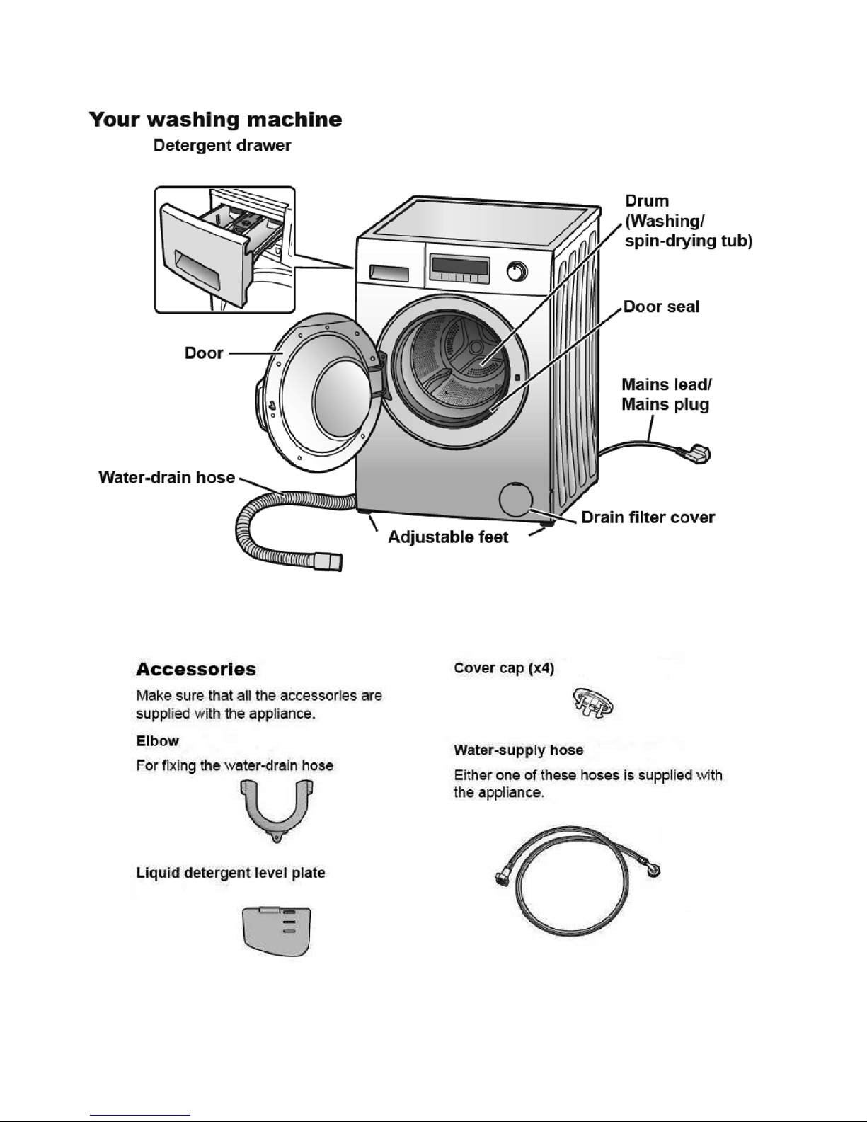
3 Location of Controls and Components

NA-127VB5WGB / 127VB5WFR / 127VB5WES / 127VB5WTA / 127VB5WPL / 127VB5WGN / 127VB5WNR /
147VB5WDE / 147VB5WGB / 147VB5WGN / 147VB5WNR
7
4 Installation Instructions
4.1. Moving and Installing
4.1.1. Removal of Transportation Screw
1. Transportation screws, which are located at the back side
of the machine, must be removed before running the
machine.
2. Loosen the screws by turning them anticlockwise with a
suitable spanner.
3. Pull out the screws and rubber washers.
4. The holes where the transport screws have been
removed should be covered with the plastic transport
caps found in the accessories bag.
5. The transportation screws that have been removed from
the machine must be re-used in any future transporting of
the machine.
4.1.2. Foot Adjustment
1. Do not install machine on rugs or similar surfaces.
2. For machine to work silently and without any vibration, it
should be installed on a flat, non-slippery firm surface.
Any suspended floor must be suitably strengthened.
3. You can adjust the level of machine using its feet.
4. First, loosen the plastic adjustment nut away from the
cabinet base.
5. Change the level by adjusting the feet upwards or downwards.
6. After level has been reached, tighten the plastic adjustment nut again by rotating it upwards against the base of
the cabinet.
7. Never put cartons, wooden blocks or similar materials
under the machine to balance irregularities of the floor.
4.1.3. Electrical Connection
1. Washing machine requires a 50Hz supply of 220240Volts.
2. A special earthed plug has been attached to the supply
cord of washing machine. This plug must be fitted to an
earthed socket. The fuse value fitted to this plug should
be 13 amps. If you have any doubts about electrical supply, consult a qualified electrician.
THIS APPLIANCE MUST BE EARTHED.
Insert the machine’s plug to a grounded socket which you
can easily reach.

NA-127VB5WGB / 127VB5WFR / 127VB5WES / 127VB5WTA / 127VB5WPL / 127VB5WGN / 127VB5WNR /
147VB5WDE / 147VB5WGB / 147VB5WGN / 147VB5WNR
8
4.1.4. Water Supply Connection
1. Washing machine is supplied with a single (cold) water
inlet.
2. To prevent leakage from the connection joints, a rubber
washer is included in the hose packing. Fit this washer at
the end of water inlet hose on the tap side.
3. Connect the hose to the water inlet valve. Tighten the
plastic connector by hand. Please call a qualified plumber
if you are unsure about this.
4. Water pressure of 0,1-1 MPa from tap will enable
machine to work more efficiently.(0,1 MPa pressure
means water flow of more than 8 litres in 1 minute from a
fully opened tap)
5. After connection is complete, check for leakage by turning
on tap completely.
6. Make sure that water inlet hoses can not become folded,
damaged, stretched or crushed when the washing
machine is in its final position.
7. Mount the water inlet hose to a 3/4” threaded water tap.
4.1.5. Drain Connection
1. Make sure that water inlet hoses are not folded, twisted,
crushed or stretched.
2. The drain hose should be mounted at a minimum height
of 60 cm, and a maximum height of 100 cm from the floor.
3. The end of the drain hose can be con nected directly to a
drainage stand-pipe or alternatively to a specific connection point designed for that purpose on the waste outlet of
a sink unit.
4. Do not extend the drain hose or guarantee will be invalidated.
4.2. Detergent Box Group

NA-127VB5WGB / 127VB5WFR / 127VB5WES / 127VB5WTA / 127VB5WPL / 127VB5WGN / 127VB5WNR /
147VB5WDE / 147VB5WGB / 147VB5WGN / 147VB5WNR
9
5 Operating Instructions
5.1. LCD Screen, Function Buttons & Knobs
PR Program selector 16 programs including off position
SW1 Switch 1, Start / Pause
SW2 Switch 2, Temperature Selection
SW3 Switch 3, Spin Speed Selection
SW4 Switch 4, Delay Timer Selection
SW5 Switch 5, Extra Rinse Option
SW6 Switch 6, Easy Ironing Option
SW7 Switch 7, Eco/Speed Mode Option
SS1 7 Segment LCD for Temperature Display I8 Extra Rinse Symbol
SS2 7 Segment LCD for Spin Speed Display I9 Easy Ironing Symbol
SS3 7 Segment LCD for Remaining Time I10 Eco Mode Symbol
I1 Child Lock Symbol I11 Speed Mode Symbol
I2 Door Lock Symbol I12 Cold Wash Symbol
I3 Drain Phase Symbol I13 Temperature Sign
I4 Spin Phase Symbol I14 Program Proceeding Zone
I5 Rinse Phase Symbol Slow Blink ON 0.5 sec, OFF 0.5 sec, ON 0.5 sec
I6 Wash Phase Symbol Fast Blink ON 0.10 sec, OFF 0.10 sec, ON 0.10 sec
I7 Delay Symbol

NA-127VB5WGB / 127VB5WFR / 127VB5WES / 127VB5WTA / 127VB5WPL / 127VB5WGN / 127VB5WNR /
147VB5WDE / 147VB5WGB / 147VB5WGN / 147VB5WNR
10
5.2. Program Details

NA-127VB5WGB / 127VB5WFR / 127VB5WES / 127VB5WTA / 127VB5WPL / 127VB5WGN / 127VB5WNR /
147VB5WDE / 147VB5WGB / 147VB5WGN / 147VB5WNR
11
5.3. Child Lock
Activation
Press SW7 for 5 seconds.
The Child Lock Symbol on appears on the LCD display as
Child Lock is active.
Deactivation
Press SW7 for 5 seconds.
The Child Lock Symbol will disappear on LCD displayupon
deactivation.
6 Test Mode
6.1. Autotest
Set PR to program 3 (Colours)
While pressing SW5 (Extra Rinse), change position of the PR from third program to second (Cotton-Prewash), and release the SW5
after keep more than 5 seconds.
Autotest starts.

NA-127VB5WGB / 127VB5WFR / 127VB5WES / 127VB5WTA / 127VB5WPL / 127VB5WGN / 127VB5WNR /
147VB5WDE / 147VB5WGB / 147VB5WGN / 147VB5WNR
12

NA-127VB5WGB / 127VB5WFR / 127VB5WES / 127VB5WTA / 127VB5WPL / 127VB5WGN / 127VB5WNR /
147VB5WDE / 147VB5WGB / 147VB5WGN / 147VB5WNR
13
7 Service Mode
7.1. Service Autotest
1. Set PR to program 3 (Colours) and press SW2 (TC)
2. While pressing the SW2, change PR position from third to
second, and release the SW2 after keep more than 5 seconds.
3. Bring PR to desired test step (1st ,2nd or 3rd program
position) as soon as [SAU] is displayed on LCD.
LCD Display status:
I2 Door Lock Symbol -> Fixed on
SS3 -> SAU
The test steps are as below ;
Step 1:
Selector Program 1 (Cotton) will be [HEATER ON]
Before heating it should take water till first level frequency
then start heating.
Heater will be on max. 8 minutes after this 8 minutes if the
temp. doesn’t change more than 2C then it will give N TC
failure. (E05).
Or if the NTC connection is broken then it should give again
E05 NTC failure.
At the end of heating, [SAU] visualization should make slow
blink to indicate that the step is over.
Note:
If user changes the selector position, machine will do what
is defined for the new selected position.
Step 2:
Selector Program 2 (Cotton Prewash) will be [PUMP ON]
Temperature will be measured, if it is higher than 50 C, it
should take 60 sec. cooling water, and then make [Drain + 5
sec.]
At the end of pump activation, [SAU] visualization shoul d
make slow blink to indicate that the step is over.
Step 3:
Selector position 3 (Colours) will be a 12 mins test program
where all functions of the appliance will be checked.
Machine will make exactly the same algorithm of Super
Rapid 12'. So, time for selector position 3 is 12 minutes.
At the end of test program [End] is visualized on LCD and
door is unlocked.

NA-127VB5WGB / 127VB5WFR / 127VB5WES / 127VB5WTA / 127VB5WPL / 127VB5WGN / 127VB5WNR /
147VB5WDE / 147VB5WGB / 147VB5WGN / 147VB5WNR
14
7.2. Failure Codes
8 Troubleshooting Guide
All repairs which must be done on the machine should be done by authorized agents only. When a repair is required for machine or
you are unable to eliminate the failure with the help of the information given below:
• Unplug the machine.
• Close the water tap.
Error Indication Error Number Indication For User Indication For Service
Yes/No Yes/No
Door is not locked E01 Yes Yes
Door is unlocked during programme E01 Yes Yes
Lack of water E02 Yes Yes
Pump failure E03 Yes Yes
Overflow E04 Yes Yes
NTC or Heater Failure E05 No Yes
Motor Failure - 1 (T achometer open-short circuit or
motor connector is disconnected)
E06 No Yes
Motor Failure - 2 (triac short circuit) E08 No Yes
Electronic Pressure Sensor E10 No Yes
FAILURE PROBABLE CAUSE METHODS OF ELIMINATION
Machine does not operate.
It is unplugged. Insert the plug into the socket.
Fuse is defective. Change fuse.
Start / Pause button has not been
pressed.
Press the start / pause button.
The program knob is in 0 (off) status. Bring the program knob on the desired status.
The door is not shut properly. Shut the door properly. You should hear the click.
Child lock is active. See section 5.3.
Machine does not receive water.
Water tap is closed. Open water tap.
The water inlet hose may be bent. Check the water inlet hose.
The ater inlet hose is obstructed. Clean the filters of water inlet hose.
The water inlet filter is obstructed. Clean the valve inlet filters.
The door is not shut properly. Shut the door properly. You should hear the click.
Machine is not draining water.
The drain hose is obstructed or bent. Check the drain hose.
The pump filter is obstructed. Clean the pump filter.
The clothes are not placed inside the
machine in a well-balanced manner.
Spread the clothes inside the machine in an orderly and
well-balanced manner.
Machine is vibrating.
The feet of machine are not adjusted. Adjust the feet.
Transportation screws are not
removed. Remove transportation screws.
There is a small amount of clothes in
the device.
It does not prevent operation of the machine.
Excessive amount of clothes are filled
in the machine or the clothes are not
placed in a well-balanced manner.
Do not exceed the recommended quantity of clothes
and spared clothes in the machine in a well-balanced
manner.
Excessive foam in the detergent
drawer
Too much detergent has been used. Press the start/pause button. In order to stop the foam,
dilute one table-spoon of softener in half liter of water
and pour it in the detergent drawer. Press the start/
pause button after 5-10 minutes. Arrange the amount of
the detergent properly in the next washing process.
Wrong detergent has been used. Use only the detergents produced for full automatic
machines.
The washing result is bad.
Laundry too dirty for the program you
have selected.
Select a suitable program.
The amount of detergent used is not
sufficient.
Use more detergent according to the detergent.
The washing result is not good.
Clothes exceeding the maximum
capacity has been filled in machine.
Put the clothes in machine in a manner not to exceed
its maximum capacity.
Water may be hard. Use the amount of detergent accord ing to the declara-
tion of the detergent producer.
Distribution of the clothes in machine is
not well-balanced.
Spread the clothes inside the machine in an orderly and
well-balanced manner.
The water is seen in the drum
during washing.
No failure. The water is at the lower
part of the drum.

NA-127VB5WGB / 127VB5WFR / 127VB5WES / 127VB5WTA / 127VB5WPL / 127VB5WGN / 127VB5WNR /
147VB5WDE / 147VB5WGB / 147VB5WGN / 147VB5WNR
15
There are residues of detergent
on the clothes.
The pieces of some detergents which
do not dissolve in water may stick to
clothes as white stains.
By calibrating machine for [Rinsing] program, make an
additional rinsing or eliminate the stains After drying
with the help of a brush.
There are grey stains
on the clothes.
These stains may be caused by oil,
cream or ointment.
In the next washing operation, use the maximum detergent amount declared by the detergent producer.
The spinning process is not done
or starts with delay.
No failure. The unbalanced load control
works in that way.
The unbalanced load control system will try to distribute
clothes in a homogenous manner. After clothes are distributed, passage to spinning process will be realized.
In the next washing process, place clothes into the
machine in a well-balanced manner.
FAILURE PROBABLE CAUSE METHODS OF ELIMINATION

NA-127VB5WGB / 127VB5WFR / 127VB5WES / 127VB5WTA / 127VB5WPL / 127VB5WGN / 127VB5WNR /
147VB5WDE / 147VB5WGB / 147VB5WGN / 147VB5WNR
16
9 Critical Torque Valuess
The bolts/nuts above are important for product safety purposes. Please tighten screw, bolts and nuts according to the torque values
given in table above.
Assembly Location Bolt/Nut Torque Min.
(Nm)
Torque Nom.
(Nm)
Torque Max.
(Nm)
Air Pressure
Wrench. (rpm)
* Transport Screw Assembly Transport Screws 6.50 6.50 7.00 1000
* Motor Assembly Motor Screws 6.00 6.50 7.50 800
*
Front Concrete Weight - Front
Tub Assembly
Front Counterweight Screws 14.00 14.50 14.75 600
* Upper Counter Weight Assembly Upper Counterweight Screws 25.00 27.50 30.00 440
*
Pulley - Drive Shaft - Washing
Group Assembly
Pulley - Drive Shaft Assembly
Bolt
39.50 40.00 40.50 440
* Heater Assembly Heater Assembly Nut 3.85 4.00 4.00 970
 Loading...