

Panasonic mva18fbas6hbcp, mva24fbas6hbcp, mva30fbas6hbcp, mva36fbas6hbcp, mva42fbas6hbcp Operation Manual
...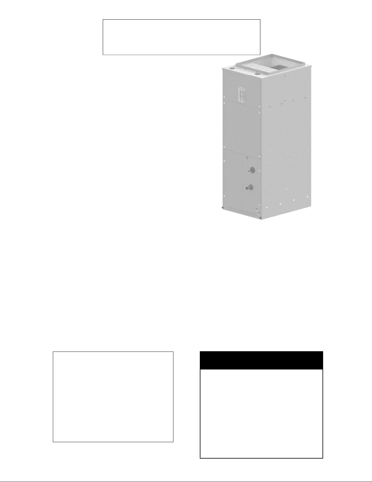
MVA Series Air Handling Unit
Installation, Operation and Maintenance
Manual
MVA Series units are direct drive vertical and
multi-position Air Handlers delivering nominal cooling capacities of 1.5 to 5 tons. Units
may be specified with hot water or electric heating coils to meet space cooling loads or heating
loads or both. Two styles of unit orientation are
available for maximum flexibility.
How to Use this Manual:
This manual gives instructions regarding installation, operation and maintenance for the
MVA Series air handling units.
Use these instructions in conjunction with
other appropriate instructions, including but
not limited to those instructions supplied with
the outdoor unit. Installation must comply
with all applicable local codes.
SAFETY WARNING:
Installer should pay particular attention to
the following words:
NOTE–intended to clarify or make installation easier.
CAUTION–given to prevent equipment
damage.
WARNING–to alert installer that personal
injury and/or equipment damage may
result if installation procedure is not
properly followed.
GENERAL
Installation and maintenance are to be performed only by qualified personnel who are familiar with local codes and regulations and are
experienced with HVAC equipment of this type.
WARNING: Sharp edges, coil surfaces
and rotating fans are a potential injury
hazard – avoid contact.
WARNING: Hazardous voltage – Disconnect and Lock Out all incoming power
sources before servicing or installing unit.
ELECTRIC SHOCK CAN CAUSE DEATH.
WARNING: This equipment may be installed well above finished floor—Use extreme caution when working at heights.
UNPACKING-CHECK FOR DAMAGE!
Immediately inspect each unit for damage upon receipt.
Inspect units for external and concealed
damage immediately.
File any damage claims in accordance
with the Freight Damage Policy and
Terms and Conditions.
Do not repair damaged units without
written authorization.
Protect stored units from damage.
035-000039-001 Page 1 of 32 MVA IOM 1.3 9-10-2014

THIS PAGE INTENTIONALLY LEFT BLANK
035-000039-001 Page 2 of 32 MVA IOM 1.3 9-10-2014
MVA Series Air Handling Unit
Installation, Operation and Maintenance
Manual
/ŶƐƚĂůůĂƟŽŶ ^ƚĂƌƚ-Up
and Service
/ŶƐƚƌƵĐƟŽŶƐ
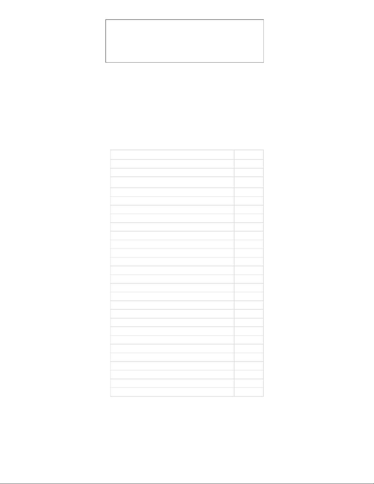
Topic Page
SAFETYCONSIDERATIONS
PRODUCT NOMENCLATURE
UNPACKING
INSTALLATION
Pre-installation
Rigging
Unpackaging
Service Clearances
Return Air & Unit Orientation
Vertical to Horizontal Conversion (EEV)
Unit Suspension or Floor Mount
Condensate Drain
Ductwork
Refrigerant Piping
Electric Heater Accessory
Electrical
START-UP
Fan Airflow Step-Up
Airflow Data
SERVICE
Fan & Fan Motor
Filters
Access Panels
Coil & Drain Pan Service
ELECTRICAL RATINGS
DIMENSIONS
Startup Report
1, 5
6-7
8
8
8
8
8
8,11
9
10
8,12,13
12
12
14
14-15
16-21
22-23
23-24
23-24
25-28
25-26
27
27
28
29
30
31
035-000039-001 Page 3 of 32 MVA IOM 1.3 9-10-2014

THIS PAGE INTENTIONALLY LEFT BLANK
035-000039-001 Page 4 of 32 MVA IOM 1.3 9-10-2014
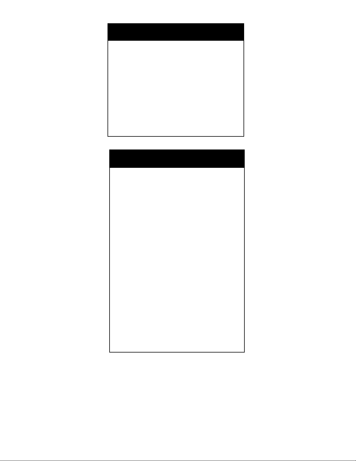
DANGER
NEVER enter an enclosed fan cabinet or reach into
a unit while the fan is running.
LOCK OPEN AND TAG the fan motor power disconnect switch before working on a fan. Take fuses
with you and note removal on tag. Electric shock
can cause personal injury or death.
LOCK OPEN AND TAG the electric heat coil power
disconnect switch before working on or near heaters.
Failure to follow these warnings could lead to personal injury or death.
WARNING
CHECK the assembly and component weights to
be sure that the rigging equipment can handle
them safely.
Note also, the centers of gravity and any specific
rigging instructions.
CHECK for adequate ventilation so that fumes will
not migrate through ductwork to occupied spaces
when welding or cutting inside air-handling unit
cabinet or plenum.
WHEN STEAM CLEANING COILS be sure that
the area is clear of personnel.
DO NOT attempt to handle access covers and removable panels on outdoor units when winds are
strong or gusting until you have sufficient help to
control them. Make sure panels are properly secured while repairs are being made to a unit.
DO NOT remove access panel fasteners or open
access doors until fan is completely stopped. Pressure developed by a moving fan can cause excessive force against the panel which can injure personnel.
DO NOT work on dampers until their operators are
disconnected.
BE SURE that fans are properly grounded before
working on them.
Failure to follow these warnings could result in personal injury or equipment damage.
035-000039-001 Page 5 of 32 MVA IOM 1.3 9-10-2014
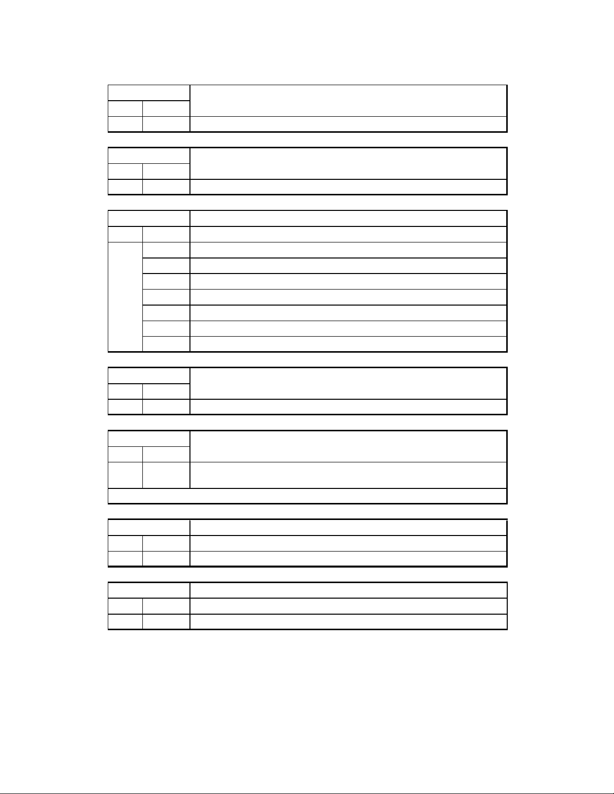
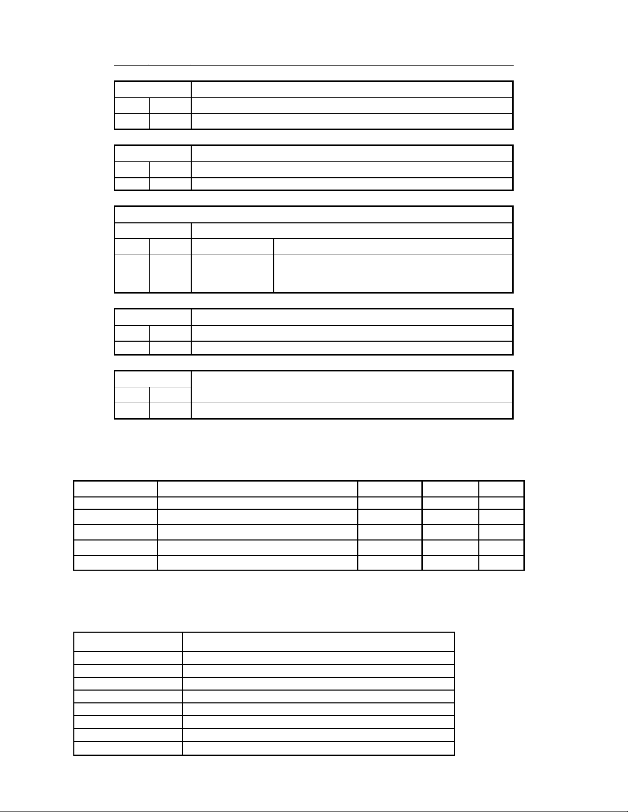
PRODUCT NOMENCLATURE
Unit Type/Size
Code Selection
01, 02 MV
Generation/Series
Code Selection
03 A
Unit Type/Size
Code Selection NOM Capacity
18
24
30
04, 05
Primary Coil Type
Code Selection
06
36
42
48
60
F
Description
Direct Drive Multiposition air handling unit
Description
Revision Level
Description
18,000 Btu/hr
24,000 Btu/hr
30,000 Btu/hr
36,000 Btu/hr
42,000 Btu/hr
48,000 Btu/hr
60,000 Btu/hr
Description
4 ROWDX with electronic expansion valve,R-410a
HeatingCoil
Code Selection
07
Future Use Description
Code Selection
08
Unit Grade Description
Code Selection
09
Description
Electric Heat Ready (readyto accept field installed EH Accessory kit, ordered
B
Future Use
A
Standard
S
separately)
035-000039-001 Page 6 of 32 MVA IOM 1.3 9-10-2014
Selection
Selection
OrderingNumber
Selection
Selection
Selection
PRODUCT NOMENCLATURE—CONT’D
Unit Voltage
Code
10
Controls
Code
11 H
ReturnAir Cabinet Options
Code
12
DrainPan
Code
13
Tracking Description
Code
14
Description
208/230/1/60 ECM-VE(customer change transformer tapfor 208V)
6
Description
Internal Use
Description
Unit Orientation
Vertical (Front RH Cond
Drain Cnx)or Horizontal
B
C
P
Right
Description
drain panandcabinet insulationtype
Fiberglass, Universal Drainpan - Galvanized
Internal Use
ReturnLocation
Bottom Return
Accessory Electric Heater Kits
P/N Description Unit Size Power kW*
012-000458-001 FC EH-HEATER MVA-3-1-240 3KW MVA18-60 240/1/60 3
012-000458-002 FC EH-HEATER MVA-5-1-240 5KW MVA18-60 240/1/60 5
012-000458-003 FC EH-HEATER MVA-6-1-240 6KW MVA18-60 240/1/60 6
012-000458-004 FC EH-HEATER MVA-8-1-240 8KW MVA18-60 240/1/60 8
012-000458-005 FC EH-HEATER MVA-9.5-1-240 9.5KW MVA18-60 240/1/60 9.5
*Note: If unit power is 208V/1ph/60Hz, then the kW is reduced to 75% of the table value.
Accessory Filter Kits
P/N Description
473-550115-001 2" FILTER RACK MERV 8 - MVA18/24
473-550115-002 2" FILTER RACK MERV 8 - MVA30/36
473-550115-003 2" FILTER RACK MERV 8 - MVA42/48
473-550115-004 2" FILTER RACK MERV 8 - MVA60
473-550116-001 4" FILTER RACK MERV 13 - MVA18/24
473-550116-002 4" FILTER RACK MERV 13 - MVA30/36
473-550116-003 4" FILTER RACK MERV 13 - MVA42/48
473-550116-004 4" FILTER RACK MERV 13 - MVA60
035-000039-001 Page 7 of 32 MVA IOM 1.3 9-10-2014
INSTALLATION
Pre-installation
1. Check items received against packing list.
2. Do not stack unit components or accessories during storage. Stacking can cause
damage or deformation.
3. If unit is to be stored for more than 2 weeks
prior to installation, observe the following
precautions:
a. Choose a dry storage site that is rea-
sonably level and sturdy to prevent undue stress or permanent damage to the
unit structure or components. Do not
store unit on vibrating surface. Damage
to stationary bearings can occur. Set
unit off ground if in heavy rain area.
b. Remove all fasteners and other small
parts from jobsite to minimize theft. Tag
and store parts in a safe place until
needed.
c. Cover entire unit with a tarp or plastic
coverall. Extend cover under unit if
stored on ground. Secure cover with
adequate tie-downs or store indoors.
Be sure all coil connections have protective shipping caps.
d. Monthly — Remove tarp from unit, en-
ter fan section through access door or
through fan inlet, and rotate fan and
motor slowly by hand to redistribute the
bearing grease and to prevent bearing
corrosion.
Rigging — Do not remove shipping skids or
protective covering until unit is ready for final
placement. Use slings and spreader bars as applicable to lift unit. Do not lift unit by coil connec-
tions or headers.
Do not remove protective caps from coil
piping connections until ready to connect
piping.
WARNING-AUXILIARY DRAIN PAN
RECOMMMENDED:
This product has an auxiliary condensate drain
which should be piped to a condensate overflow
sensor or safe drain location or both to protect
the equipment and property from damage in the
case of condensate overflow.
In addition, the International Mechanical Code
(IMC) section 307.2.3 requires the use of auxiliary drain pans. Many municipalities have
adopted this code.
This practice represents the standard for professional installation whether or not this code has
been adopted in a specific municipality or territory. As such, water damages that would have
been prevented had an auxiliary pan been deployed will not be considered for compensation.
This position is taken regardless of whether the
source of the moisture was specified as a potential failure mode in the applicable building
code or not. A freeze burst, cracked drain pan,
failed weld, or corrosion induced leak are some
of the potential failure modes that are mitigated
when an auxiliary pan is properly installed. Professional installers recognize the value of protecting customer assets against foreseeable
events. Customers who choose to avoid the
cost of common protective measures waive their
right to seek damages when those foreseeable
events occur. If the product is located above a
living space or where damage may result from
condensate overflow, install a watertight pan of
corrosion-resistant metal beneath the unit to
catch over-flow which may result from clogged
drains or from other reasons. Provide proper
drain piping for this auxiliary pan. Consult local
codes for additional precautions before installation.
Unpackaging
1. Remove all packaging and any foreign material from unit.
2. Check blower wheel for free rotation.
3. Check copper lines, coil etc. for internal or
hidden damage.
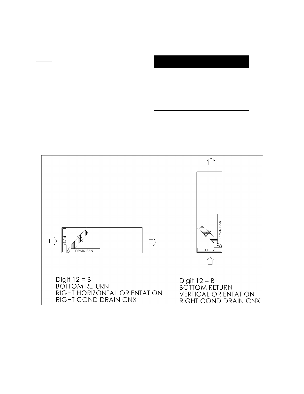
Return Air and Unit Orientation
Units may be positioned in several configura-
tions depending on the return air configuration selected—see Figure 1.
NOTE: Right and left return units are not
recommended for horizontal installation.
Service Clearance
inches) of clearance. This allows substantial freedom in the positioning of the unit to
best serve the requirements of the structure.
Unit Support
Floor mounting: Unit may be mounted on a
housekeeping pad, floor, platform or plenum.
Provide a suitable isolation pad to minimize
sound transmission to the structure. CAU-
TION! Make sure to allow enough elevation to permit construction of the condensate trap. Also allow enough elevation
and clearance for opening the filter door
(removes to the front). See Service Clear-
ances.
The fan coil is completely serviceable from
the front. Units are approved for 0” (zero
035-000039-001 Page 8 of 32 MVA IOM 1.3 9-10-2014
INSTALLATION
NOTE:
Electronic Expansion Valve (EEV)
must be oriented vertically, and is
shipped for vertical cabinet orientation.
For horizontal cabinet orientation,
follow procedure to rotate the EEV
assembly. Refer to Figure 2.
Return Configurations and
Unit Orientations
WARNING
FOR HORIZONTAL CABINET ORIENTATION, EEV MUST BE ROTATED TO
VERTICAL POSITION! Failure to reorient the EEV can result in improper
unit operation or equipment damage
or dangerous condition.
Figure 1
035-000039-001 Page 9 of 32 MVA IOM 1.3 9-10-2014
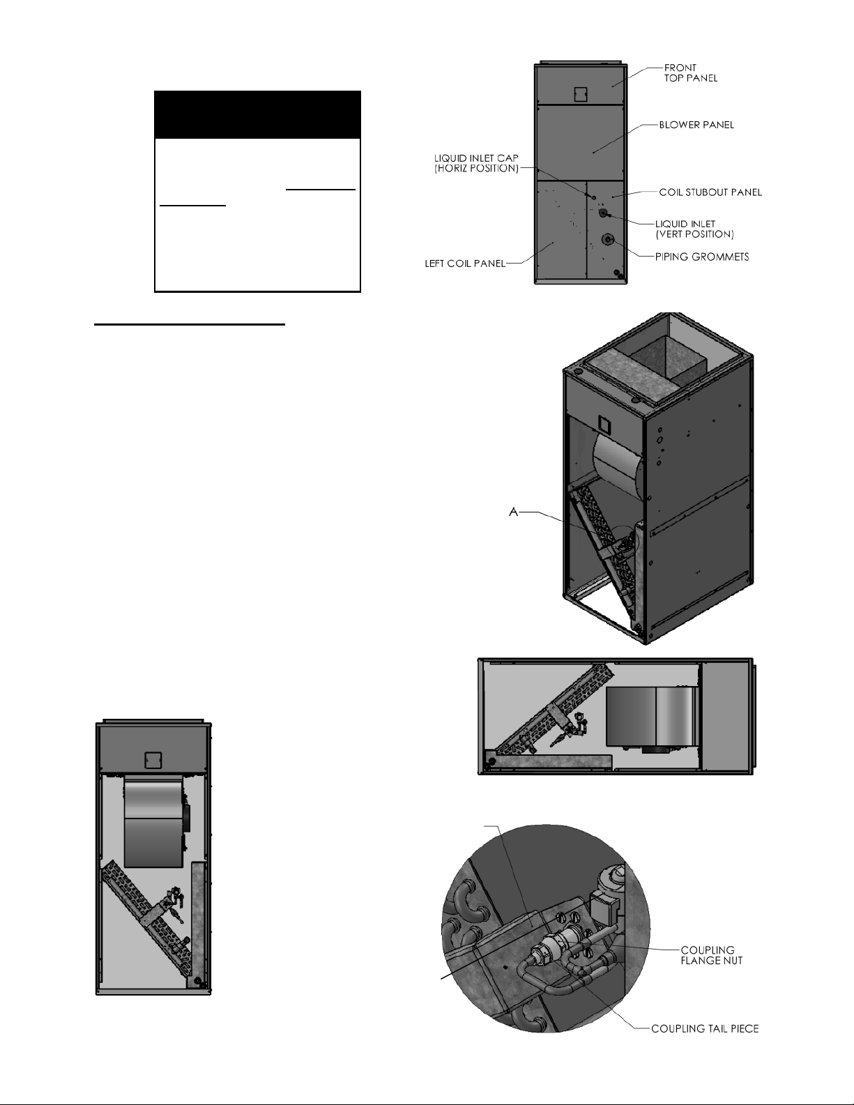
INSTALLATION—VERTICAL TO HORIZONTAL CONVERSION—EEV ROTATION
WARNING
FOR HORIZONTAL CABINET
ORIENTATION, EEV MUST
BE ROTATED TO VERTICAL
POSITION! Failure to reorient the EEV in VERTICAL
position can result in improper unit operation or equipment damage or dangerous
condition.
CONVERSION PROCEDURE:
1. UNIT IS SHIPPED WITH NITROGEN
CHARGE. IF UNIT HAS ALREADY BEEN
CHARGED WITH REFRIGERANT, REMOVE REFRIGERANT CHARGE PER LOCAL CODES BEFORE PERFORMING CONVERSION PROCEDURE.
2. REMOVE PIPING PLUGS AND SAVE FOR LATER USE. NITROGEN WILL DISCHARGE FROM
COIL.
3. REMOVE PIPING GROMMETS; REMOVE LIQUID INLET CAP FOR HORIZONTAL POSITION.
4. REMOVE BLOWER PANEL, LEFT AND RIGHT
COIL PANELS
5. SECURE EEV BRACKET WITH WRENCH AND
TURN COUPLING FLANGE NUT COUNTER
CLOCKWISE WITH 3/4" WRENCH TO LOOSEN
AND DISCONNECT COUPLING. THE COUPLING TAIL NUT SHOULD BE ALLOWED TO
TURN FREELY.
6. REPOSITION EXPANSION VALVE ASSEMBLY
AS SHOWN IN FIGURE 2d. ENSURE EXPANSION VALVE IS VERTICAL WITHIN +/- 15 DEG
WITH UNIT INSTALLED IN HORIZONTAL POSITION
7. REATTACH COUPLING AND
TIGHTEN TO 10-12 FT LBS
WHILE SECURING EEV BRACKET WITH WRENCH.
8. AS AN ALTERNATIVE TO
STEP 5 COUPLING MAY BE
TIGHTENED UNTIL NO
THREADS ARE SHOWING
AND COUPLING IS BOTTOMED OUT. THEN TURN
AN ADDITIONAL 60 DEG
(OR ONE HEX FLAT) TO
TIGHTEN.
9. REINSTALL FRONT
PANELS, GROMMETS,
AND PIPING PLUGS.
Figure 2a-
Vertical
Orientation
Figure 2b-
Vertical
Orientation
Figure 2d-Horizontal
Orientation
EEV BRACKET
Detail A-
EEV Detail
EEV INVERTICAL
ORIENTATION
Figure 2c-Vertical
Orientation, Panels
Removed
035-000039-001 Page 10 of 32 MVA IOM 1.3 9-10-2014
 Loading...