

Page 1
Operating Instructions (Basic)
AC Servo Motor & Driver
MINAS A5-series
• Thank you for purchasing this
Panasonic product.
• Before operating this product,
please read the instructions
carefully, and save this manual for
future use.
*
This product image is 1.5kW type of A5-series.
If you are the rst user of this product, please be sure to read the downloaded
Operating Instructions (Overall) from our Web Site.
[Web address of Motor Company, Panasonic Corporation]
http://industrial.panasonic.com/ww/i_e/25000/motor_fa_e/motor_fa_e.html
Make sure to forward these Operating Instructions for safety to the nal user.
<Contents>
1. Introduction ................................. B2
On Opening the Product Package .................. B2
Check of the Driver Model ..............................
Check of the Motor Model
2. Installation................................... B4
Driver .............................................................. B4
Motor ............................................................... B6
3. System Conguration and
Wiring ........................................... B8
Overall Wiring (Connector type) ..................... B8
Overall Wiring (Terminal block type)
Driver and List of Applicable Peripheral Equipments
Wiring of the Main Circuit (Connector type)
Wiring of the Main Circuit (Terminal block type)
Wiring method to connector
Wiring Diagram .............................................
Wiring of connector for motor and brake ......
Wiring to the Connector, X1 .........................
Wiring to the Connector, X2 .........................
Wiring to the Connector, X3 .........................
Wiring to the Connector, X4 .........................
............................... B3
.............................
page page
Wiring to the Connector, X5 .........................
Wiring to the Connector, X6 .........................
B2
Wiring to the Connector, X7 .........................
4. Parameter .................................. B31
Outline / Setup / Connection ......................... B31
Composition of Parameters ..........................
5. Protective Functions ................ B34
Protective Function (What Is Error Code ?)
6.
Maintenance and Inspections
7. Conformity to EC Directives
.................
B10
.... B12
......... B14
... B16
and UL Standards ..................... B38
Composition of Peripheral Equipments ........ B40
8. Built-in Holding Brake .............. B44
9. Dynamic Brake.......................... B46
B17
10.
B19
B21
B22
B22
B23
B24
Check of the Combination of
the Driver and the Motor
Incremental Specications, 20-bit ............... B47
Absolute Specications, 17-bit ................... B48
11. Specications ......................... B49
After-Sale Service (Repair) .......... B52
............ B47
IMD88
B27
B28
B30
B33
......
B34
.... B36
English
Page 2
−B2−
−B3−
English
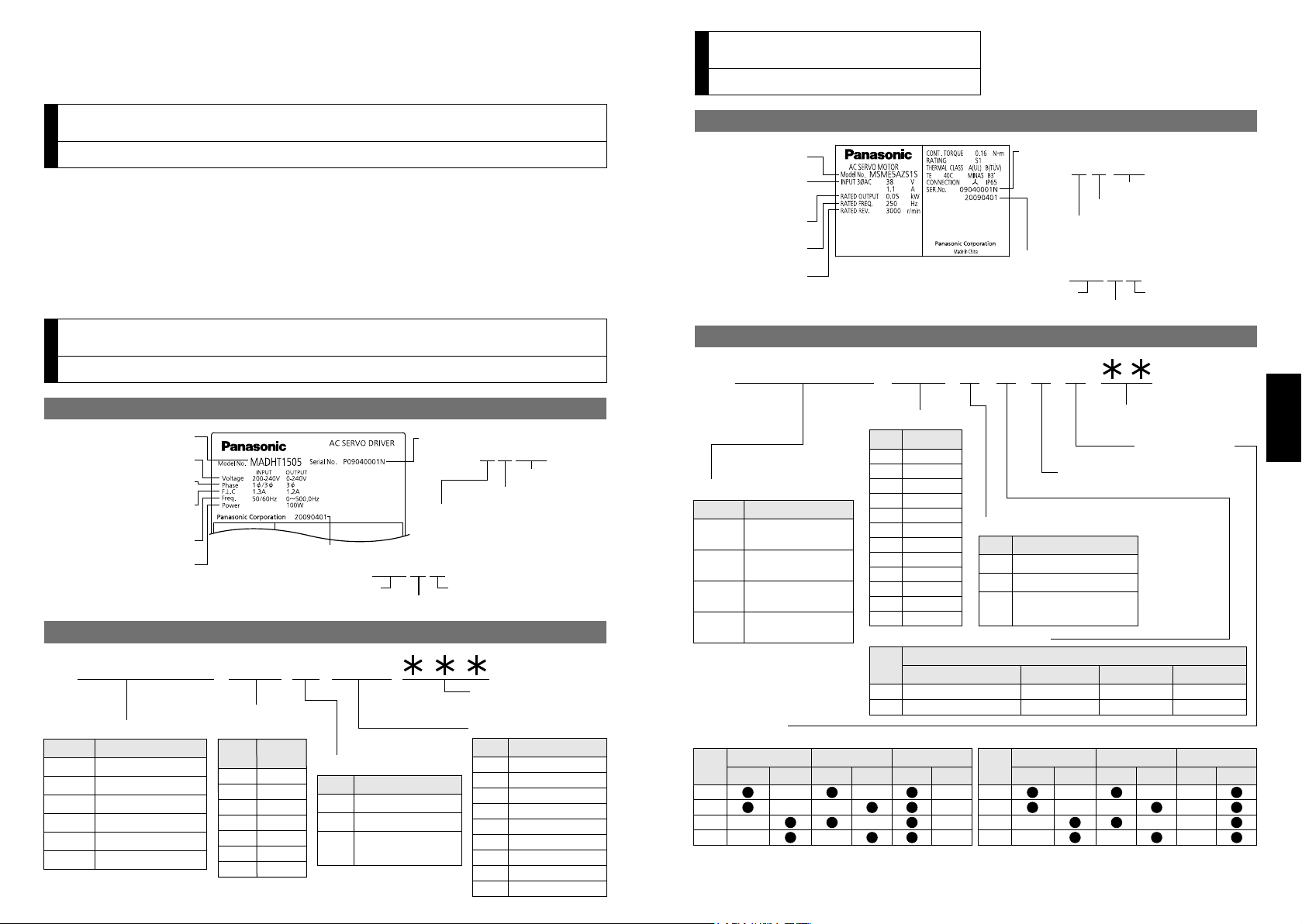
M A D H T 1 5 0 5
Special specifications
(letters and numbers)
Current detector rating
Power supply
Max. current rating
of power device
Frame-size symbol
MADH
MBDH
MCDH
MDDH
MEDH
MFDH
Frame
Symbol
A5-series, A-frame
A5-series, B-frame
A5-series, C-frame
A5-series, D-frame
A5-series, E-frame
A5-series, F-frame
T1
T2
T3
T5
T7
TA
TB
Current
rating
Symbol
Specifications
10A
15A
30A
50A
70A
100A
150A
Symbol
1
3
5
Single phase, 100V
3-phase, 200V
Single/3-phase,
200V
05
07
10
20
30
40
64
90
A2
Current rating
Symbol
5A
7.5A
10A
20A
30A
40A
64A
90A
120A
1 to 4 75 to 6 10 to 128 to 9
Serial Number
e.g.) : 09 04 000 1N
Lot number
Month of production
Year of production
(Lower 2 digits of AD year)
Manufacture date
e.g.) : 2009 0 4 01
Manufacture dateManufacture year
Manufacture month
Model
Rated output
Rated input
voltage/current
Rated frequency
Rated
rotational speed
M S M E 5 A Z S 1 S
1 to 4
5 to 6
11 to 12
7 8 9 10
Special specifications
Motor structure
Design order 1: Standard
Rotary encoder specifications
Voltage specifications
Specifications
Type
Symbol
Low inertia
(50W to 5.0kW)
Middle inertia
(1.0kW to 5.0kW)
Middle inertia
(900W to 3.0kW)
High inertia
(1.0kW to 5.0kW)
G
S
Incremental
Absolute
Specifications
Symbol
Format
Pulse count
Output
Motor rated output
Symbol
Specifications
Symbol
Resolution
5-wire
7-wire
Wire count
Motor structure
MSME
(50W to 750W)
*1
The product with oil seal is a special order product.
*2 Key way with center tap
[
Products are standard stock items or manufactured by order. For details, inquire the dealer.]
A
B
S
T
Shaft
Holding brake
Oil seal
Without
With
Round
Key way
Without
With
Symbol
MSME
(1.0kW to 5.0kW)
, MDME, MGME, MHME
C
D
G
H
Shaft
Holding brake
Oil seal
Without
With
Round
Key way
Without
With
Symbol
*1
*2
*2
MSME
MDME
MGME
MHME
5A
01
02
04
08
09
10
15
20
30
40
50
50W
100W
200W
400W
750W
900W
1.0kW
1.5kW
2.0kW
3.0kW
4.0kW
5.0kW
1
2
Z
100 V
200 V
100/200 common
(50W only)
20bit
17bit
1,048,576
131,072
1. Introduction
Model number
Input/output voltage
Rated output of
applicable motor
Rated input/output
current
Input/output frequency
Number of phase
Serial Number
e.g.) :
P0 9 0 4000 1 N
Lot number
Month of production
Year of production
(Lower 2 digits of AD year)
Manufacture date
e.g.) : 2009 0 4 01
Manufacture dateManufacture year
Manufacture month
Check of the Motor Model
1. Introduction
On Opening the Product Package
• Make sure that the model is what you have ordered.
• Check if the product is damaged or not during transportation.
• Check if the Operating Instructions (safety) are included or not.
• Check if the power connector, motor connectors, connector for external regenerative
resistor connection (only E-frame) and safety by-pass plug are included or not.
(Neither the power connector nor motor connector are included to F-frame.)
1. Introduction
Check of the Driver Model
Contents of Name Plate
Model Designation
Contents of Name Plate
Model Designation
Page 3
−B4−
−B5−
English
2. Installation
Fan Fan
100mm
or more
100mm
or more
40mm
or
more
40mm
or
more
10
mm
or
more
10
mm
or
more
10
mm
or
more
Direction of air flowing
from the internal
cooling fan (D/E/F frame)
Control panel
A to D-frame
E, F-frame
Basemount (Standard)
[Rear mount]
Frontmount
[Use mounting fixture]
Front or Basemount
[Use mounting fixture]
Mounting fixture
(optional parts)
Mounting
fixture
(Attachment)
Fastening torque of earth screws (M4)
to be 0.7 to 0.8 N•m.
Fastening torque of earth screws (M5)
to be 1.4 to 1.6 N•m.
Driver
2. Installation
Driver
Install the driver properly to avoid a breakdown or an accident.
Installation Place
1)
Install the driver in a control panel enclosed in noncombustible material and placed indoor
where the product is not subjected to rain or direct sunlight. The products are not waterproof.
2) Where the products are not subjected to corrosive atmospheres such as hydrogen
sulde, sulfurous acid, chlorine, ammonia, sulfur, chloric gas, sulfuric gas, acid, alkaline and salt and so on, and are free from splash of inammable gas.
3) Where the motor is free from grinding oil, oil mist, iron powder or chips.
4) Well-ventilated and low humidity and dust-free place.
5) Vibration-free place.
Environmental Conditions
Item Conditions
Ambient temperature
0˚C to 55˚C (free from freezing)
Ambient humidity 20% to 85% RH (free from condensation)
*
Storage temperature
1
–20˚C to 65˚C (Max.temperature guarantee: 80˚C for 72 hours)
Storage humidity 20% to 85% RH (free from condensation)
Vibration Lower than 5.88m/s2 (0.6G), 10 to 60Hz
Altitude Lower than 1000m
*
Extreme temperatures are permissible only for short period such as during transportation.
1
How to Install
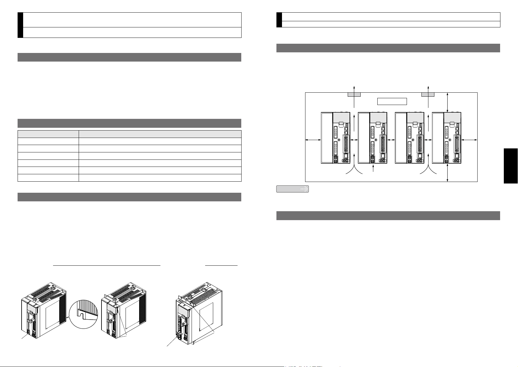
1) Rack-mount type. Install in vertical position, and reserve enough space around the
servo driver for ventilation.
2) Base mount (rear mount) is standard for A/B/C/D-frame driver.
3) To change the mounting surface of A/B/C/D-frame driver, use the optional mounting
xture. For choosing the correct optional mounting xture, refer to the Operating In-
structions (Overall).
4)
For the dimensions and mass of the product, which are necessary design data of
the mounting section, refer to the dimensional outline drawing on the Operating Instructions (Overall) or the Delivery Specication.
Mounting Direction and Spacing
• Reserve enough surrounding space for effective cooling.
• Install fans to provide uniform distribution of temperature in the control panel.
• D/E/F frame is provided with a cooling fan at the bottom.
Observe the environmental conditions of the control panel described in the previous page.
•
Note
It is recommended to use the conductive paint when you make your own
mounting xture, or repaint after peeling off the paint on the machine for
installing the products, in order to make noise countermeasure.
Caution on Installation
•
We have been making the best effort to ensure the highest quality, however, application
of exceptionally large external noise disturbance and static electricity, or failure in input
power, wiring and components may result in unexpected action. It is highly recommended that you make a fail-safe design and secure the safety in the operative range.
•
If stranded wires are used as the cable, bunch the conductors of the cable using a ferrule.
If stranded wires are used as they are, unexpected accidents such as an electric shock
and short circuit or injury may result. (Refer to P.B17. “Wiring method to connector”.)
• There might be a chance of smoke generation due to the failure of these products.
Pay an extra attention when you apply these products in a clean room environment.
• Be sure to ground the protective earth terminal.
If the product is grounded insufciently, not only the driver may not deliver its perfor
mance sufciently, but also safety hazards such as a malfunction due to a electri-
cation or a disturbance may be caused.
If electric wires are bound and run through metal duct, they cannot carry the rated
•
current due to temperature rise. If they are forced to carry the rated current, they may
burn. When determining size of the wire, check the current decreasing coefcient by
referring to the Operating Instructions (Overall).
-
Page 4
−B6−
−B7−
English
2. Installation
Cable
Motor
Oil / Water
Motor
Motor
2. Installation
Motor
Install the motor properly to avoid a breakdown or an accident.
Installation Place
Since the conditions of location affect a lot to the motor life, select a place
which meets the conditions below.
1) Indoors, where the products are not subjected to rain or direct sun beam. The prod
-
ucts are not waterproof.
2) Where the products are not subjected to corrosive atmospheres such as hydrogen
sulde, sulfurous acid, chlorine, ammonia, sulfur, chloric gas, sulfuric gas, acid, alkaline and salt and so on, and are free from splash of inammable gas.
3) Where the motor is free from grinding oil, oil mist, iron powder or chips.
4) Well-ventilated and humid and dust-free place, far apart from the heat source such
as a furnace.
5) Easy-to-access place for inspection and cleaning
6) Vibration-free place.
7)
Avoid enclosed place. Motor may gets hot in those enclosure and shorten the motor life.
Environmental Conditions
Item Conditions
Ambient temperature
Ambient humidity 20% to 85% RH (free from condensation)
Storage temperature
Storage humidity 20% to 85% RH (free from condensation)
Vibration Motor only Lower than 49m/s2 (5G) at running, 24.5m/s2 (2.5G) at stall
Impact Motor only Lower than 98m/s2 (10G)
Enclosure
rating
*
1 Ambient temperature to be measured at 5cm away from the motor.
*
2 Permissible temperature for short duration such as transportation.
*
3 These motors conform to the test conditions specified in EN standards (EN60529,
EN60034-5). Do not use these motors in application where water proof performance is
required such as continuous wash-down operation.
*
4 This condition is applied when the connector mounting screw in case of motor 750W or
less are tightened to the recommended tightening torque (Refer to P.B21, 28, 29). Be
sure to use mounting screw supplied with the connector.
Motor only
(Connector type)
Altitude Lower than 1000m
*
1
0˚C to 40˚C (free from freezing)
*
2
–20˚C to 65˚C (Max.temperature guarantee: 80˚C for 72 hours)
IP67 (except rotating portion of output shaft and connecting pin
part of the motor connector and the encoder connector)
*3*
4
How to Install
You can mount the motor either horizontally or vertically as long as you observe the followings.
1) Horizontal mounting
• Mount the motor with cable outlet facing downward for water/oil countermeasure.
2) Vertical mounting
• Use the motor with oil seal (make-to-order in case of motor 750W or less) when
mounting the motor with gear reducer to prevent the reducer oil/grease from enter-
ing to the motor.
3) For the dimensions and mass of the product, which are necessary design data of
the mounting section, refer to the dimensional outline drawing on the Operating Instructions (Overall) or the Delivery Specication.
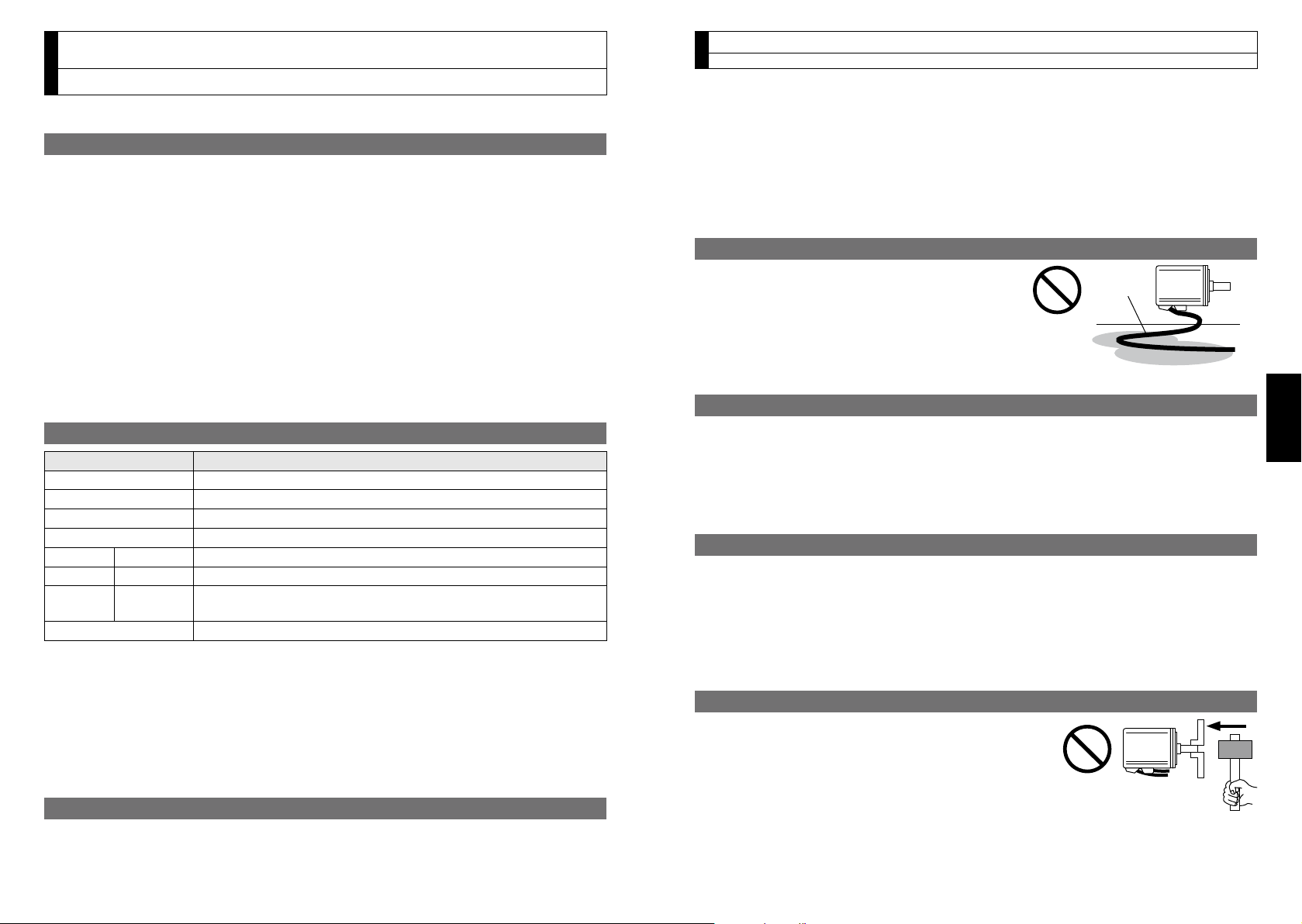
Oil/Water Protection
1) Don't submerge the motor cable to water or oil.
2) Install the motor with the cable outlet facing
downward.
3) Avoid a place where the motor is always sub
-
jected to oil or water.
4) Use the motor with an oil seal when used with
the gear reducer, so that the oil may not enter to the motor through shaft.
Stress to Cables
1) Avoid a stress application to the cable outlet and connecting portion by bending or
self-weight.
2) Especially in an application where the motor itself travels, x the attached cable and
contain the extension junction cable into the bearer so that the stress by bending
can be minimized.
3) Take the cable bending radius as large as possible. (Minimum R20mm)
Permissible Load to Output Shaft
1) Design the mechanical system so that the applied radial load and/or thrust load to
the motor shaft at installation and at normal operation can meet the permissible
value specied to each model.
2) Pay an extra attention when you use a rigid coupling. (Excess bending load may
damage the shaft or deteriorate the bearing life.)
3)
Use a exible coupling with high stiffness designed exclusively for servo application in order
to make a radial thrust caused by micro misalignment smaller than the permissible value.
Notes on Installation
1) Do not apply direct impact to the shaft by hammer
while attaching/detaching a coupling to and from
the motor shaft.
(Or it may damage the encoder mounted on the
other side of the shaft.)
2) Make a full alignment.
3)
If the motor shaft is not electrically grounded, it may cause electrolytic corrosion to
(incomplete alignment may cause vibration and damage the bearing.)
the bearing depending on the condition of the machine and its mounting environment,
and may result in the bearing noise. Check and verication by customer is required.
Page 5
−B8−
−B9−
English
Junction cable
for brake
: High voltage
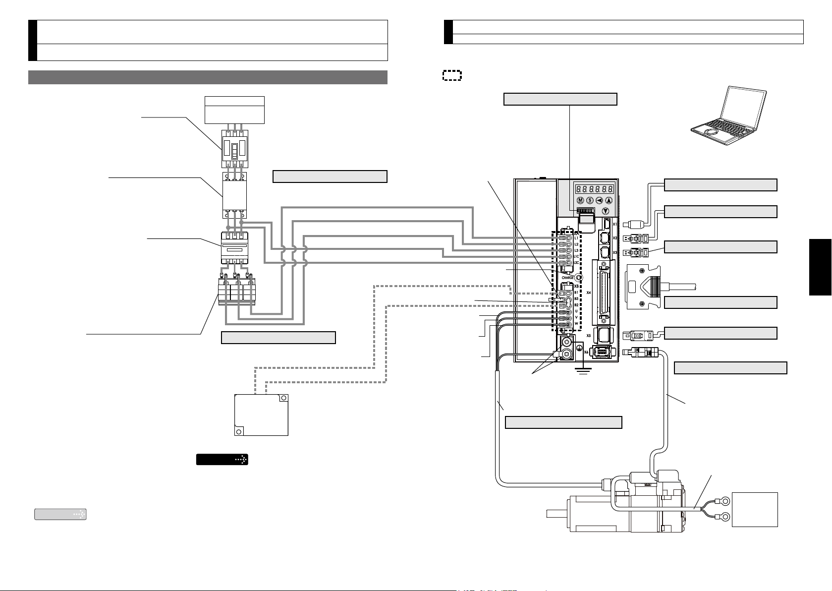
• Wiring of Main Connector (XA)
• Wiring of Motor Connector (XB)
Regenerative resistor (optional)
• When you use an external regenerative
resistor, install an external protective
apparatus, such as thermal fuse without fail.
• Thermal fuse and thermostat are built in to
the regenerative resistor (Option). If the
thermal fuse is activated, it will not resume.
• Mount the regenerative resistor on
incombustible material such as metal.
PC (to be supplied by customer)
Setup support software “PANATERM”
Please download from our web site.
L1 (Pin-5)
L2 (Pin-4)
L3 (Pin-3)
L1C (Pin-2)
L2C (Pin-1)
Charg lamp
(LED)
*1
Ground
(earth)
Protective earth
terminals
• Connection to input power
Wiring to Connector, XA
• Monitor output
Wiring to Connector, X7
• Connection to PC or host controller
Wiring to Connector, X1
• Connection to RS232, RS485
or host controller
Wiring to Connector, X2
• Connection to Safety by-pass plug
(Refer to P.B23)
Wiring to Connector, X3
• Connection to host controller
Wiring to Connector, X4
• Connection to feedback scale
Wiring to Connector, X5
• Connection to encoder
Wiring to Connector, X6
• Connection to external components
Wiring to Connector, XB
• Connection to motor driving phase
and ground
Wiring to Connector, XB
Handle lever
Use this for connector
connection. Store this after
connection for other occasions. (Refer to P.B18 for
connection.)
Remarks
Junction cable for encoder
Junction cable for motor
Circuit Breaker (MCCB)
To protect power supply line from
overloading, install a wiring circuit
breaker rated to the capacity of the
power supply.
Noise Filter (NF)
Removes external noise from the
power lines. And reduces an effect
of the noise generated by the servo
driver.
Magnetic Contactor (MC)
Turns on/off the main power of the
servo driver.
Use coil surge suppression units
together with this.
• Never start nor stop the servo
motor with this Magnetic
Contactor.
Reactor (L)
Reduces harmonic current of the
main power.
DC Power supply for brake
DC24V
(to be supplied by customer)
Pin B1 (6-pin), B2 (4-pin), and
B3 (5-pin)
• B2 and B3 to be kept shorted for
normal operation.
• When you connect an external
regenerative resistor, disconnect
a short circuit wire between B2
and B3, then connect the external
regenerative resistor between B1
and B2, set up Pr0.16 to 1 or 2.
Note that no regenerative resistor is
equipped in Frame A and B type.
Short circuit wire
(B2-B3)
U-phase
(red)
V-phase
(white)
W-phase
(black)
B1 (Pin-6)
B2 (Pin-4)
Note
Mains
Residual
current device
*1 Do not make displacement, wiring or inspection
while the LED is lit - cause of electric shock.
3. System Conguration and Wiring
Overall Wiring (Connector type)
Connecting Example of A to D-frame
3. System Conguration and Wiring
Overall Wiring (Connector type)
Page 6
−
B10
−
−
B11
−
English
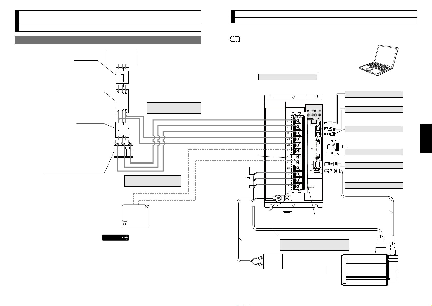
: High voltage
Setup support software “PANATERM”
Please download from our web site.
Connection with input
power supply
Connection to external
components
Connection to motor driving
phase and ground
Short bar
(B2-B3)
B1
B2
U-phase
(red)
V-phase
(white)
W-phase
(black)
L3
L2
L1
L2C
L1C
Ground
(earth)
Charg lamp
(LED)
*1
Junction cable
for brake
DC Power supply for brake
DC24V
(to be supplied by customer)
Junction cable
for encoder
PC (to be supplied by customer)
• Monitor output
Wiring to Connector, X7
• Connection to PC or host controller
Wiring to Connector, X1
• Connection to RS232, RS485
or host controller
Wiring to Connector, X2
• Connection to Safety by-pass plug
(Refer to P.B23)
Wiring to Connector, X3
• Connection to host controller
Wiring to Connector, X4
• Connection to feedback scale
Wiring to Connector, X5
• Connection to encoder
Wiring to Connector, X6
Regenerative resistor (optional)
• When you use an external regenerative
resistor, install an external protective
apparatus, such as thermal fuse without fail.
• Thermal fuse and thermostat are built in to
the regenerative resistor (Option). If the
thermal fuse is activated, it will not resume.
• Mount the regenerative resistor on
incombustible material such as metal.
Remarks
• Wiring of the Main Circuit
Pin B1, B2 and B3
• B1 and B2 to be kept shorted for
normal operation.
• When you connect an external
regenerative resistor, disconnect
a short bar between B1 and B2,
then connect the external
regenerative resistor between P
and B2, set up Pr0.16 to 1 or 2.
Pin NC
• Do not connect anything.
Junction cable for motor
Protective
earth
terminals
• Wiring of Main Connector (XA)
Circuit Breaker (MCCB)
To protect power supply line from
overloading, install a wiring circuit
breaker rated to the capacity of the
power supply.
Noise Filter (NF)
Removes external noise from the
power lines. And reduces an effect
of the noise generated by the servo
driver.
Magnetic Contactor (MC)
Turns on/off the main power of the
servo driver.
Use coil surge suppression units
together with this.
• Never start nor stop the servo
motor with this Magnetic
Contactor.
Reactor (L)
Reduces harmonic current of the
main power.
Mains
Residual
current device
*1 Do not make displacement, wiring or inspection
while the LED is lit - cause of electric shock.
3. System Conguration and Wiring
Overall Wiring (Terminal block type)
Connecting Example of F-frame
3. System Conguration and Wiring
Overall Wiring (Terminal block type)
Page 7
−
B12
−
−
B13
−
English
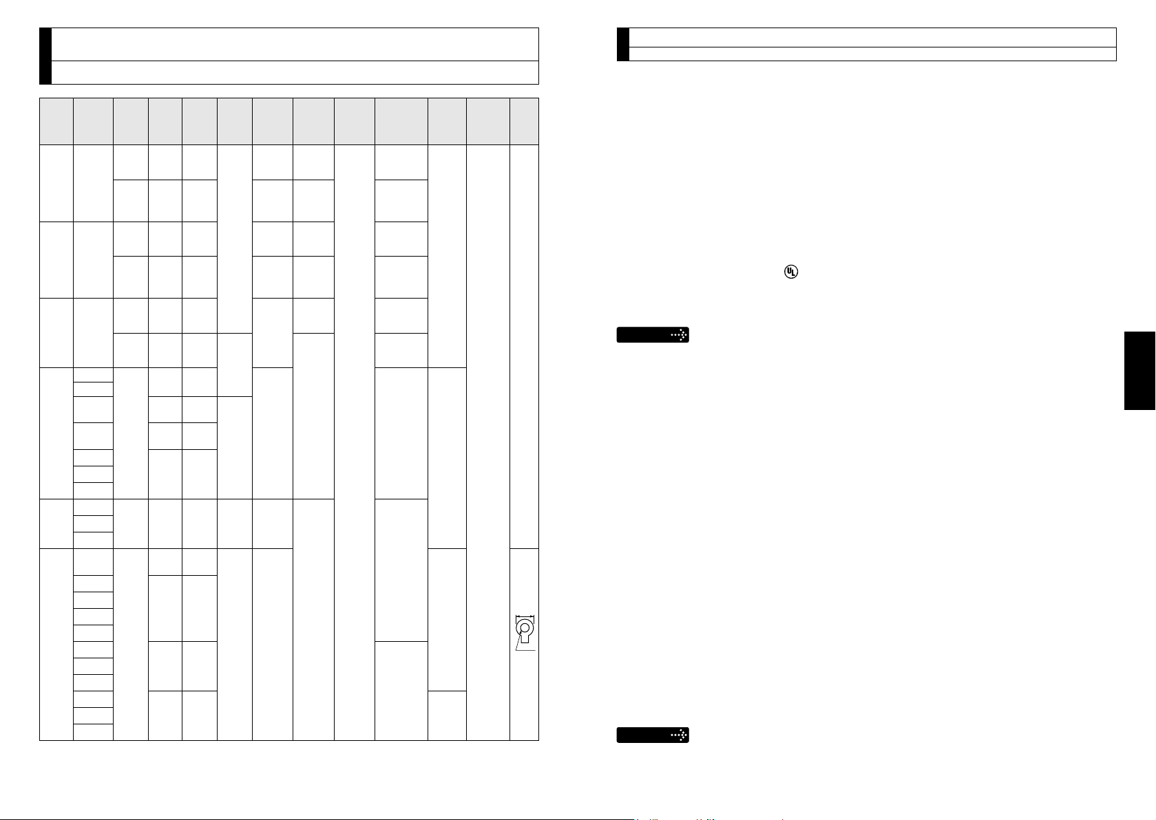
3. System Conguration and Wiring
11mm or
smaller
ø5.3
Driver and List of Applicable Peripheral Equipments
Required
Applicable
Driver
MADH
MBDH
MCDH
MDDH
MEDH
MFDH
*
*
motor
MSME
*
2
MSMD
*
2
MHMD
MSME
*
2
MSMD
*
2
MHMD
MSME
*
2
MSMD
*
2
MHMD
MDME
MHME
MGME
MSME
MHME
MDME
MSME
MDME
MSME
MHME
MGME
MDME
MHME
MSME
MGME
MDME
MHME
MSME
MDME
MHME
MSME
1 The model number of Magnetic contactor is the one of Panasonic Electric Works.
2 Can drive 20-bit incremental encoder type MINAS-A4 motor. (PN: M*MD***G1*)
Voltage
Single
phase,
100V
Single/
3-phase,
200V
Single
phase,
100V
Single/
3-phase,
200V
Single
phase,
100V
Single/
3-phase,
200V
Single/
3-phase,
200V
3-phase,
200V
3-phase,
200V
Rated
output
50W to
100W
50W to
200W
200W
400W
400W
750W
1.0kW
900W
1.0kW
1.5kW
2.0kW
2.0kW
3.0kW
4.0kW
5.0kW
Circuit
Power
breaker
(at the rated
(rated
load)
current)
approx.
0.4kVA
approx.
0.5kVA
approx.
10A
0.5kVA
approx.
0.9kVA
approx.
0.9kVA
approx.
1.3kVA
15A
approx.
1.8kVA
approx.
1.8kVA
approx.
1.8kVA
20A
approx.
2.3kVA
approx.
30A
3.3kVA
approx.
3.8kVA
approx.
4.5kVA
50A
approx.
6kVA
approx.
7.5kVA
Noise
lter
absorber
DV0P4170 DV0P4190
DV0P4170
DV0P4190
/
DV0PM
DV0P1450
20042
DV0P4170 DV0P4190
DV0P4170
DV0P4190
/
DV0PM
DV0P1450
20042
DV0P4190
DV0PM
20042
DV0P4190
DV0P1450
DV0P4220
DV0PM
20043
DV0P1450
DV0P3410
Surge
/
/
/
Noise
lter for
signal
DV0P1460
Magnetic
contactor
BMFT61041N
(3P+1a)
BMFT61542N
(3P+1a)
BMFT61041N
(3P+1a)
BMFT61542N
(3P+1a)
BMFT61541N
(3P+1a)
BMFT61542N
(3P+1a)
BMFT61842N
(3P+1a)
BMF6352N
(3P+2a2b)
BMF6652N
(3P+2a2b)
Cable
*
1
diameter
(main
circuit)
0.75mm2/
AWG18
2.0mm2/
AWG14
3.5mm2/
AWG12
5.3mm2/
AWG10
Cable
diameter
(control
circuit)
0.75mm2/
AWG18
3. System Conguration and Wiring
Driver and List of Applicable Peripheral Equipments
• Select peripheral equipments for single/3phase common specication according to
Connection
Connection to exclusive connector
Terminal
block
M5
the power source.
[For details of peripheral equipments]
Noise lter .............................
Surge absover .......................
Noise lter for signal lines .....
• About circuit breaker and magnetic contactor
To comply to EC Directives, install a circuit breaker between the power and the
noise lter without fail, and the circuit breaker should conform to IEC Standards and
UL recognized (Listed and marked).
Suitable for use on a circuit capable of delivering not more than 5,000 rms symmetri
cal amperes, below the maximum input voltage of the product.
Remarks
• Select a circuit breaker and noise lter which match to the capacity of power supply
(including a load condition).
• Terminal block and protective earth terminals
Use a copper conductor cables with temperature rating of 60˚C or higher.
The screws of protective earth terminals for Frame A to D are M4 and M5 for
Frame E, F.
Tighten the terminal block screw on frame F with a torque between 1.0 and 2.0
N·m. Application of overtorque (more than 2.0 N·m) will cause damage to terminal
block. Maximum allowable torque to the screw securing terminal block cover is 0.2
N·m.
• The cable diameter of an earth cable.
Use an earth cable with the same diameter or larger as that of the main circuit
cable.
If the diameter of the main circuit cable is 1.6mm
a diameter of 2.0mm
•
Use the attached exclusive connector for A to E-frame, and maintain the peeled off
length of 8 to 9mm. (Refer to P.B17)
•
Tighten the screws of the connector, Connector X4 for the host controller with the
torque of 0.3 to 0.35 N·m.
Larger torque than 0.35N·m may damage the connector at the driver side.
Caution
Do not turn on power without tightening all terminal block screws properly, otherwise, loose
contacts may generate heat (smoking, ring).
2
(AWG14).
P.B41
P.B42
P.B43
2
or less, use an earth cable with
-
Page 8
−
B14
−
−
B15
−
English
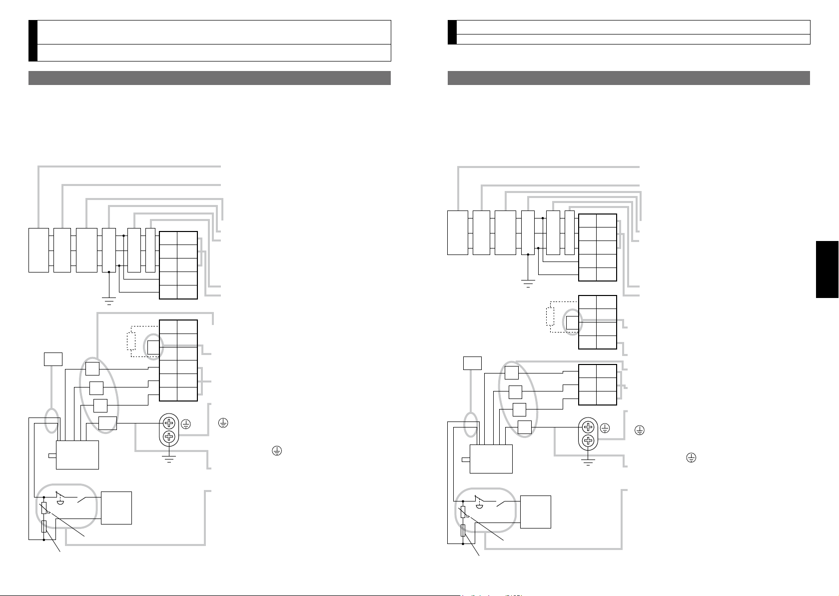
3. System Conguration and Wiring
Motor
Varistor
DC
24V
MCCB
Power
supply
NF MC
U
V
W
E
L
Fuse (5A)
• Check the name plate of the driver for power
specifications.
• Provide a residual current device. The
residual current device to be the one
designed for "Inverter" and is equipped with
countermeasures for harmonics.
• Provide a circuit breaker.
• Make sure to provide a noise filter.
• Provide coil surge suppression units to the
coil of the Magnetic Contactor recommended
by manufacturer.
Never start/stop the motor with this
Magnetic Contactor.
• Provide an AC Reactor.
• Connect L1 and L1C, and L3 and L2C at
single phase use (100V and 200V), and
don't use L2.
•
Match the colors of the motor lead wires to those
of the corresponding motor output terminals
(U,V,W).
•
Don't disconnect the shorting cable between B2
and B3 (C and D frame type). Disconnect this only
when the external regenerative register is used.
• Avoid shorting and grounding. Don't
connect the main power.
• Earth-ground this.
• Make sure to
connect the protective earth terminal
( ) of the driver and the protective earth (earth
plate) of the control panel to prevent electrical shock.
• Don't co-clamp the earth wires to the protective
earth terminal ( ) . Two terminals are
provided.
• Don't connect the earth cable to other
inserting slot, nor make them touch.
• Compose a duplex Brake Control Circuit so that
the brake can also be activated by an external
immediate stop signal.
• The Electromagnetic Brake has no polarity.
• For the capacity of the electromagnetic brake
and how to use it, refer to P.B44,
"Specifications of Built-in Holding Brake".
• Provide a varistor.
Connect a 5A fuse in series with the varistor.
Ground resistance: 100 Ω max.
For applicable wire,
refer to P.B13.
L1C
L3
L2
L1
L2C
B1
B3
B2
U
V
W
XA
XB
2
3
4
5
1
2
3
4
5
6
1
DC power supply
for brake
Red
Black
Green or
Green/yellow
White
Yellow
(X2)
RCD
Motor
Varistor
DC
24V
U
V
W
E
Fuse (5A)
• Check the name plate of the driver for power
specifications.
• Provide a residual current device. The
residual current device to be the one
designed for "Inverter" and is equipped with
countermeasures for harmonics.
• Provide a circuit breaker.
• Make sure to provide a noise filter.
• Provide coil surge suppression units to the
coil of the Magnetic Contactor recommended
by manufacturer.
Never start/stop the motor with this
Magnetic Contactor.
• Provide an AC Reactor.
• Connect L1 and L1C, and L3 and L2C at
single phase use (100V and 200V), and
don't use L2.
•
Don't disconnect the shorting cable between B2
and B3. Disconnect this only when the external
regenerative register is used.
• Do not connect anything to NC.
•
Match the colors of the motor lead wires to those of
the corresponding motor output terminals (U,V,W).
• Avoid shorting and grounding. Don't connect
the main power.
• Earth-ground this.
• Make sure to
connect the protective earth terminal
( ) of the driver and the protective earth (earth
plate) of the control panel to prevent electrical shock.
•
Don't co-clamp the earth wires to the protective
earth terminal ( ) . Two terminals are provided.
• Don't connect the earth cable to other
inserting slot, nor make them touch.
• Compose a duplex Brake Control Circuit so that
the brake can also be activated by an external
immediate stop signal.
• The Electromagnetic Brake has no polarity.
• For the capacity of the electromagnetic brake
and how to use it, refer to P.B44, "Specifications
of Built-in Holding Brake".
• Provide a varistor.
Connect a 5A fuse in series with the varistor.
Ground resistance: 100 Ω max.
For applicable wire, refer to P.B13.
L1C
L3
L2
L1
L2C
B1
B3
NC
U
V
W
XA
XC
XB
2
3
4
5
1
2
3
1
3
B2
2
4
1
DC power supply
for brake
Red
Black
Green
White
Yellow
(X2)
MCCB
Power
supply
NF MC LRCD
Wiring of the Main Circuit (Connector type)
3. System Conguration and Wiring
Wiring of the Main Circuit (Connector type)
A to D-frame, 100 V / 200 V type
• Wiring should be performed by a specialist or an authorized personnel.
• Do not turn on the power until the wiring is completed.
Tips on Wiring
•
1) Wire connector (XA and XB).
2) Connect the wired connector to the driver.
E-frame, 200 V type
• Wiring should be performed by a specialist or an authorized personnel.
• Do not turn on the power until the wiring is completed.
Tips on Wiring
•
1) Wire connector (XA, XB and XC).
2) Connect the wired connector to the driver.
Page 9
−
B16
−
−
B17
−
English
3. System Conguration and Wiring
Motor
Varistor
DC
24V
L1
U
V
W
E
L2
L3
L1C
L2C
B1
B3
B2
NC
U
V
W
• Check the name plate of the driver for power
specifications.
•
Provide a residual current device. The residual
current device to be the one designed for "Inverter"
and is equipped with countermeasures for harmonics.
• Provide a circuit breaker.
• Make sure to provide a noise filter.
• Provide coil surge suppression units to the coil of
the Magnetic Contactor recommended by manufacturer. Never start/stop the motor with this
Magnetic Contactor.
• Provide an AC Reactor.
• Don't disconnect the short bar between B1 and B2.
Disconnect this only when an external regenerative
register is used.
• Do not connect anything to NC.
• Match the colors of the motor lead wires to those of
the corresponding motor output terminals (U,V,W).
• Avoid shorting and grounding.
Don't connect the main power.
• Earth-ground this.
• Make sure to connect the protective earth terminal
( ) of the driver and the protective earth (earth
plate) of the control panel to prevent electrical shock.
• Don't co-clamp the earth wires to the protective
earth terminal ( ) . Two terminals are provided.
• Don't connect the earth cable to other inserting
slot, nor make them touch.
• Compose a duplex Brake Control Circuit so that the
brake can also be activated by an external
immediate stop signal.
• The Electromagnetic Brake has no polarity.
• For the capacity of the electromagnetic brake and
how to use it, refer to P.B44, "Specifications of
Built-in Holding Brake".
• Provide a varistor.
•
Connect a 5A fuse in series with the varistor.
Ground resistance: 100 Ω max.
For applicable wire, refer to P.B13.
DC power
supply
for brake
Fuse (5A)
Red
Black
Green
White
Yellow
(X2)
MCCB
Power
supply
NF MC LRCD
8 to 9 mm
①
②
③
A
A>B
1mm or more
B
3. System Conguration and Wiring
Wiring of the Main Circuit
(Terminal block type)
F-frame, 200 V type
• Wiring should be performed by a specialist or an authorized personnel.
• Do not turn on the power until the wiring is completed.
Tips on Wiring
•
1) Take off the cover xing screws, and detach the terminal cover.
2) Make wiring
Use clamp type terminals of round shape with insulation cover for wiring to the
terminal block. For cable diameter and size, reter to "Driver and List of Applicable
Peripheral Equipments" (P.B12).
Tighten the terminal block screw with a torque between 1.0 and 2.0
3) Attach the terminal cover, and x with screws.
Tighten the screw securing the cover with a torque between 0.1 and 0.2 N
N•m.
•
m.
Wiring method to connector
• Follow the procedures below for the wiring connection to the Connector XA, XB
XC
and
.
How to connect
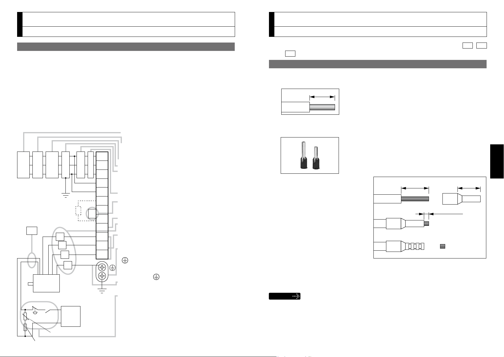
1. Peel off the insulation cover of the cable.
•
For single wire (Please obey the length in gure.)
•
For stranded wires (ferrules must be used as illustrated below).
Example: Ferrules with plastic insulating sleeve (AI series, Phoenix Contact, Ltd.)
1) Peel off th e sheath so that the
conductor portion of the cable will
protrude from the tip of the ferrule.
(It should protrude 1 mm or more
from the ferrule.)
2) Insert the cable into the ferrule
and crimp it with an appropriate
crimping tool.
3) After crimping, cut off the cable
conductor portion protruding from
the ferrule. (The allowable protrud-
ing length after cutting should be 0 to 0.5 mm.)
•
Part No. of the crimping tool:
CRIMPFOX U-D66 (1204436) Available from Phoenix Contact, Ltd.
Caution
• When peeling off the sheath of the cable, take care not to damage
other portions.
•
When crimping the ferrule, sufciently check the status of the ferrule
and cable. If the conductors of the cable stick out from the insulation
cover or protrude excessively from the tip of the ferrule, accidents such
as an electric shock and re from a short circuit may result.
Page 10

−
B18
−
−
B19
−
English
3. System Conguration and Wiring
(a) Using handle lever
* You can pull out the cable by pushing down the spring as the above.
Attach the handle lever
to the handling slot on
the upper portion. Press
down the lever to push
down the spring.
Insert the peeled cable
while pressing down the
lever, until it hits the
insertion slot (round
hole).
Release the lever.
(b) Using screw driver
Press the screw driver
to the handling slot on
the upper portion to
push down the spring.
Insert the peeled cable
while pressing down the
screw driver, until it hits
the insertion slot (round
hole).
Release the screw
driver.
Noise filterNoise filter
Motor
37
ALM+
L2
L3
L1C
L2C
B1
MC
MCCB
B3
B2
U
V
W
L1
ALM−
External regenerative resistor
(Remove the short wire when you connect
the external regenerative resistor.)
External regenerative resistor
(Remove the short wire when you connect
the external regenerative resistor.)
36
L
ON
DC12 to 24V
(±5%)
In Case of Single Phase, A to D-frame, 100 V / 200 V type
In Case of 3-Phase, A to D-frame, 200 V type
Motor
37
ALM+
L2
L3
L1C
L2C
B1
MC
MCCB
ALM
OFF
B3
B2
U
V
W
L1
Coil surge suppression units
Built-in thermostat of an external
regenerative resistor (light yellow)
ALM−
Red
White
Black
Green or
Green/Yellow
Red
White
Black
Green or
Green/Yellow
XA
XB
X4
36
L
ON
MC
DC12 to 24V
(±5%)
ALM
ALM
OFF
Built-in thermostat of an external
regenerative resistor (light yellow)
MC
ALM
Main power
supply
Control power
supply
Motor
connection
Main power
supply
Control power
supply
Motor
connection
Power supply Single phase, 100V to 120V
+10%
–15%
+10%
–15%
Single phase, 200V to 240V
+10%
–15%
+10%
–15%
Power supply 3-phase, 200V to 240V
+10%
–15%
+10%
–15%
Use a reactor for
3-phase
XA
XB
X4
When you use single phase,
connect the main power
between L1 and L3 terminals.
Remarks
Coil surge suppression units
Wiring method to connector
3. System Conguration and Wiring
Wiring Diagram
2. Insert the cable to the connector in the following 2 methods.
(a) Insert the cable using the supplied handle lever.
(b) Insert the cable using a at-blade screwdriver (Edge width: 3.0 to 3.5 mm).
1 2
1
2 3
Compose the circuit so that the main circuit power will be shut off when an error occurs.
3
Caution
• Take off the connector from the Servo Driver before making connec-
tion.
• Insert only one cable into each one of cable insertion slot.
• Pay attention to injury by screw driver.
Note
For wiring the motor connector, refer to P.B21.
Page 11

−
B20
−
−
B21
−
English
3. System Conguration and Wiring
In Case of 3-Phase, E-frame, 200 V type
In Case of 3-Phase, F-frame, 200 V type
XC
XB
Motor
37
ALM+
L2
L3
L1C
L2C
MC
MCCB
L1
ALM−
XA
X4
36
L
ON
DC12 to 24V
(±5%)
ALM
B1
B3
B2
NC
U
V
W
Motor
37
ALM+
L2
L3
L1C
L2C
MC
MCCB
L1
ALM−
X4
36
L
ON
DC12 to 24V
(±5%)
ALM
B1
B3
B2
NC
U
V
W
ALM
OFF
Built-in thermostat of an external
regenerative resistor (light yellow)
MC
ALM
OFF
Built-in thermostat of an external
regenerative resistor (light yellow)
MC
Noise filter
External regenerative resistor
(Remove the short wire when you connect
the external regenerative resistor.)
External regenerative resistor
(Remove the short wire when you connect
the external regenerative resistor.)
Red
White
Black
Green
Main power
supply
Control power
supply
Motor
connection
Main power
supply
Control power
supply
Motor
connection
Power supply 3-phase, 200V to 230V
+10%
–15%
+10%
–15%
Power supply 3-phase, 200V to 230V
+10%
–15%
+10%
–15%
Noise filter
Red
White
Black
Green
Coil surge suppression units
Coil surge suppression units
A
B
D
C
AHG
CDE
BIF
CBA
IHG
FED
A
JL04V-2E20-4PE-B-R
JL04HV-2E22-22PE-B-R
JL04V-2E20-18PE-B-R
JL04V-2E24-11PE-B-R
U-phase
V-phase
W-phase
Ground
PIN No.
B
C
D
Application
G
H
A
F
I
B
E
D
C
Brake
Brake
NC
U-phase
V-phase
W-phase
Ground
Ground
NC
PIN No.
Application
A Brake
Brake
NC
U-phase
V-phase
W-phase
Ground
Ground
NC
PIN No.
B
C
D
E
F
G
H
I
Application
Do not connect anything to NC.
<with Brake> <without Brake>
JN8AT04NJ1
1
U-phase
V-phase
W-phase
Ground
PIN No.
2
3
PE
Application
PE
3
2
1
1
2
<Motor> <Brake>
JN4AT02PJ1-R
Tightening torqueof
the screw (M2)
0.085 to 0.095 N·m (screwed to plastic)
Tightening torqueof
the screw (M2)
0.19 to 0.21 N·m
1
2
Brake
Brake
PIN No.
Application
Remarks
* Be sure to use only the screw supplied with the connector, to avoid damage.
Wiring Diagram
3. System Conguration and Wiring
Wiring of connector for motor and brake
Compose the circuit so that the main circuit power will be shut off when an error occurs.
Note
For wiring the motor connector, refer to P.B21.
• When the motors of
<MSME (50 W to 750 W)>
are used, they are connected as
shown below.
Connector: Made by Japan Aviation Electronics Industry, Ltd.
(The gures below show connectors for the motor.)
• When the motors of
<MSME (1.0 kW to 5.0 kW), MDME, MGME, MHME>
they are connected as shown below.
Connector: Made by Japan Aviation Electronics Industry, Ltd.
(The gures below show connectors for the motor.)
are used,
Page 12

−
B22
−
−
B23
−
English
3. System Conguration and Wiring
[Connector pin assignment]
(Viewed from cable)
8 6 4 2
7 5 3 1
8 6 4 2
7 5 3 1
[Connector pin assignment]
(Viewed from cable)
3. System Conguration and Wiring
Wiring to the connector, X1
This is used for USB connection to a personal computer. It is possible to change the
parameter setting and perform monitoring.
Application Symbol
USB signal terminal
Caution
Use commercially available USB mini-B connector for the driver.
VBUS 1
D− 2
D
GND 5 Connected to ground of control circuit.
Connector
Pin No.
Use for communication with personal
computer.
+
— 4 Do not connect.
3
Contents
3. System Conguration and Wiring
Wiring to the connector, X2
This is used for connection to the host controller when two or more units are used.
RS232 and RS485 interfaces are supplied.
Application Symbol
Signal ground
GND 1 Connected to ground of control circuit.
Connector
Pin No.
Contents
Wiring to the connector, X3
A safety by-pass plug is supplied as standard equipment. Do not disconnect it in nor-
mal times.
Since the standard connector cannot be used when controlling the safety function from
the host controller, purchase the optional connector and make connection as shown
below.
Caution
Application Symbol
Safety input 1
Safety input 2
If the connector is disconnected during operation, an immediate stop will
be caused.
NC
Connector
Pin No.
– 1
– 2
SF1− 3
SF1+ 4
SF2− 5
SF2+ 6
Do not connect.
These are two independent circuits that
turn off the operation signal to the power
module to shut off the motor current.
Contents
NC – 2 Do not connect.
RS232 signal
TXD 3
RXD 4
485− 5
485+ 6
RS485 signal
485− 7
485+ 8
Frame ground FG Shell
RS232
The transmission / reception method.
RS485
The transmission / reception method.
Connected with protective earth terminal in
the servo driver.
Connector (plug): 2040008-1 (optional, available from Tyco Electronics AMP)
EDM output
Frame ground
EDM− 7
EDM+ 8
FG Shell
This is an output for monitoring the failure
of the safety function.
Connected with protective earth terminal in
the servo driver.
Connector (plug): 2013595-1 (optional, available from Tyco Electronics AMP)
Page 13

−
B24
−
−
B25
−
English
3. System Conguration and Wiring
141516
174318
42
In case of open collector I/F
7
4.7kΩ
COM+
PULS2
SIGN1
SIGN2
GND
OA+
OA
-
OB+
OB
OZ+
OZ
-
GND
CZ
SPR/TRQR/SPL
GND
P-ATL/TRQR
GND
N-ATL
SP
IM
4
31256
132122
48
24
25
19
49
23
1kΩ
1kΩ
PULS1
OPC2
OPC1
INH
CL
SRV-ON
GAIN
DIV1
VS-SEL1
C-MODE
A-CLR
POT
NOT
S-RDY
+
S-RDY
-
ALM+
INP+
BRKOFF
+
BRKOFF
-
TLC
VDC
12 to 24V
ZSP
COM
-
SIGNH1
SIGNH2
PULSH1
PULSH2
GND
FG
INP
-
ALM
-
3330292728
32
31
9
8
3534373639
381110
40
124144
45
13
50
26
Z-phase output
(open collector)
3
PULS14PULS2
X4
46
47
14kΩ
10kΩ
20kΩ20kΩ
14kΩ
10kΩ
20kΩ20kΩ
47kΩ
47kΩ47kΩ
47kΩ
20kΩ
20kΩ
+
–
+
–
–
The functions of the following pin can be changed using parameters.
Input: 8, 9, 26, 27, 28, 29, 30, 31, 32, 33
Output: 10-11, 12, 34-35, 36-37, 38-39, 40
220Ω
2.2kΩ
2.2kΩ
20kΩ
2kΩ
2kΩ
20kΩ
120Ω
20kΩ
2kΩ
2kΩ
20kΩ
120Ω
220Ω
VDC
R
5
SIGN16SIGN2
220Ω
2.2kΩ
2.2kΩ
220Ω
2.2kΩ
2.2kΩ
R
1
OPC1
4
PULS2
220Ω
24VDC
2
OPC1
6
SIGN2
220Ω
2.2kΩ
2.2kΩ
2.2kΩ
2.2kΩ
(1) When you use the external
resistor with 12V and 24V
power supply
(2) When you do not use the
external resistor with 24V
power supply
Positive direction torque limit input
(0 to +10V)
Negative direction
torque limit input
(
-
10 to +10V)
Velocity monitor output
Torque monitor output
( represents twisted pair.)
Command
pulse
input A
(Use with
500 kpps or less.)
Divider
A-phase
output
B-phase
output
Z-phase
output
Command pulse input B
(Use with 4Mpps or less.)
Be sure to connect.
V
DC
12V
24V
Specifications
of R
1kW1/2W
2kW1/2W
V
DC
-
1.5
R
+
220
=10mA
.
.
Servo-ON input
Gain switching input
Electronic gear
switching input 1
Control mode
switching input
Damping control
switching input 1
Alarm clear input
Positive direction
over-travel inhibition input
Negative direction
over-travel inhibition input
Servo-Ready output
Servo-Alarm output
Positioning complete output
External brake release output
Torque in-limit output
Zero speed detection output
Deviation counter
clear input
Command pulse
inhibition input
7
4.7kΩ
COM+
OA+
OA
-
OB+
OB
OZ+
OZ
-
GND
CZ
SPR/TRQR/SPL
GND
P-ATL/TRQR
GND
N-ATL
SP
IM
212248
24
25
19
49
23
1kΩ
1kΩ
INTSPD1
INTSPD2
SRV-ON
GAIN
INTSPD3
ZEROSPD
C-MODE
A-CLR
POT
NOT
S-RDY+
S-RDY
-
ALM+
BRKOFF
+
BRKOFF
-
TLC
VDC
12 to 24V
ZSP
COM
-
FG
ALM
-
333029
27
32
31
9
8
3534373639
381110
40
12
41
50
28
1415161718
43
42
26
14kΩ
10kΩ
20kΩ20kΩ
14kΩ
10kΩ
20kΩ20kΩ
47kΩ
47kΩ47kΩ
47kΩ
20kΩ
20kΩ
X4
( represents twisted pair.)
A-phase output
B-phase output
Z-phase output
Z-phase output (open collector)
Velocity command
input (0 to ± 10V)
Positive direction torque
limit input (0 to ± 10V)
Negative direction torque
limit input (-10 to 0V)
Velocity monitor output
Torque monitor output
Servo-ON input
Gain switching input
Alarm clear input
Speed zero clamp input
Selection 1 input of
internal command speed
Selection 2 input of
internal command speed
Slection 3 input of
internal command speed
Control mode switching
input
Positive direction
over-travel inhibition input
Negative direction
over-travel inhibition input
Servo-Ready output
Servo alarm output
At-speed output
External brake release output
Torque in-limit output
Zero speed detection output
Divider
The functions of the following pin can be changed using parameters.
Input: 8, 9, 26, 27, 28, 29, 30, 31, 32, 33
Output: 10-11, 12, 34-35, 36-37, 38-39, 40
+
–
+
–
+
–
AT-SPEED
+
AT-SPEED
-
Wiring to the connector, X4
3. System Conguration and Wiring
Wiring to the connector, X4
Wiring Example of Position Control Mode
Wiring Example of Velocity Control Mode
Page 14

−
B26
−
−
B27
−
English
3. System Conguration and Wiring
7
4.7kΩ
COM+
OA+
OA
OB+
OB
OZ+
OZ
-
GND
CZ
SPR/TRQR/SPL
GND
P-ATL/TRQR
GND
N-ATL
SP
IM
212248
24
25
19
141516
174318
42
49
23
14kΩ
10kΩ
20kΩ20kΩ
14kΩ
10kΩ
20kΩ20kΩ
47kΩ
47kΩ47kΩ
47kΩ
20kΩ
20kΩ
1kΩ
1kΩ
INH
CL
SRV-ON
GAIN
DIV1
ZEROSPD
C-MODE
A-CLR
POT
NOT
S-RDY+
S-RDY
-
ALM+
AT-SPEED
+
BRKOFF
+
BRKOFF
-
TLC
VDC
12 to 24V
ZSP
COM
-
FG
AT-SPEED
-
ALM
-
33302927282632
31
9
8
3534373639
381110
40
12
41
50
Z-phase output (open collector)
X4
The functions of the following pin can be changed using parameters.
Input: 8, 9, 26, 27, 28, 29, 30, 31, 32, 33
Output: 10-11, 12, 34-35, 36-37, 38-39, 40
Divider
A-phase
output
B-phase
output
Z-phase
output
( represents twisted pair.)
Torque command input or
velocity limit input (0 to ±10V)
Velocity monitor output
Torque monitor output
Wiring example when control mode Pr0.01=0 or Pr3.17=1
CCWTL/TRQR
GND
16
17
Negative direction torque
limit input (0 to ±10V)
Select with Pr3.17.
+
–
+
–
+
–
Servo-ON input
Gain switching input
Alarm clear input
Servo-Ready output
Servo-Alarm output
At-speed output
External brake release output
Torque in-limit output
Zero speed detection output
Speed zero clamp
input
Control mode
switching input
Positive direction
over-travel inhibition input
Negative direction
over-travel inhibition input
Wiring to the connector, X4
3. System Conguration and Wiring
Wiring to the connector, X5
Wiring Example of Torque Control Mode
Connect on to Feedback Scale
Provide a power supply for the feedback scale on your part or use the following power
output (250mA or less).
Application Symbol
EX5V 1
Power supply output
EX0V 2
I/F of feedback scale
signals
EXPS 3 Serial signal
/EXPS 4
EXA 5
/EXA 6
A, B, Z phase Endoder
signal input
EXB 7
/EXB 8
EXZ 9
/EXZ 10
Frame ground
FG Shell
Connector (plug): MUF-PK10K-X (by J.S.T. Mfg. Co., Ltd.)
•
Caution
1) The manufacturers applicable feedback scales for this product are as follows.
• Mitutoyo Corp.
• Sony Manufacturing Systems Corp.
For the details of the feedback scale product, contact each company.
2)
Recommended feedback scale ratio is 1/40 ≤ Feedback scale ratio ≤ 160
If you set up the feedback scale ratio to smaller value than 50/position loop gain
(Pr1.00 and Pr.1.05), you may not be able to control per 1 pulse unit. Setup of larg
er scale ratio may result in larger noise.
Connector
Pin No.
Contents
Supply the power of feedback
scale or A, B, Z phase encoder.
Connected to ground of control
circuit.
The transmission / reception
method.
Parallel signal
reception
Connected with protective earth
terminal in the servo driver.
-
Page 15

−
B28
−
−
B29
−
English
3. System Conguration and Wiring
MSME 50W to 750W
MSME 1.0kW to 5.0kW
MDME 1.0kW to 5.0kW
MHME 1.0kW to 5.0kW
MGME 900W to 3.0kW
Shell (FG)
+5V
0V
1
2
3
4
5
6
4
1
3
7
Twisted pair
Encoder cable
Connector: JN2DS10SL1-R
(by Japan Aviation Electronics Ind.)
Motor Driver
E5V
E0V
PS
PS
9
PS
PS
FG
E5V
E0V
X6
Regulator Regulator
Shell (FG)
+5V
0V
1
2
3
4
5
6
6
3
7
4
Twisted pair
Encoder cable
Connector: JN6FR07SM1
(by Japan Aviation Electronics Ind.)
Motor Driver
E5V
E0V
PS
PS
1
PS
PS
FG
E5V
E0V
X6
Tighten the motor connector
mounting screw (M2) with a
torque between 0.19 and
0.21 N•m. To avoid damage,
be sure to use only the
screw supplied with the
connector.
[Connector pin assignment]
(Viewed from cable)
2
5
1
3
6
4
7
Shell (FG)
+5V
0V
1
2
3
4
5
6
4
1
3
7
Twisted pair
Encoder cable
Connector: JN2DS10SL1-R
(by Japan Aviation Electronics Ind.)
Motor Driver
E5V
E0V
PS
PS
9
PS
5
BAT−
6
BAT+
PS
FG
E5V
E0V
X6
Shell (FG)
+5V
0V
1
2
3
4
5
6
6
3
7
2
5
4
Twisted pair
Encoder cable
Connector: JN6FR07SM1
(by Japan Aviation Electronics Ind.)
Motor Driver
E5V
E0V
PS
PS
1
PS
BAT−
BAT+
PS
FG
E5V
E0V
X6
battery
battery
Regulator Regulator
MSME 50W to 750W
MSME 1.0kW to 5.0kW
MDME 1.0kW to 5.0kW
MHME 1.0kW to 5.0kW
MGME 900W to 3.0kW
Tighten the motor connector
mounting screw (M2) with a
torque between 0.19 and
0.21 N•m. To avoid damage,
be sure to use only the
screw supplied with the
connector.
[Connector pin assignment]
(Viewed from cable)
2
5
1
3
6
4
7
Wiring to the connector, X6
Connection to Encoder
• In case of 20-bit incremental encoder
3. System Conguration and Wiring
Wiring to the connector, X6
• In case of 17-bit absolute encoder
Page 16

−
B30
−
−
B31
−
English
3. System Conguration and Wiring
Connector X7
Manufacturer’s part No.: 530140610
Manufacturer: Japan Molex Inc.
6 1
X7
Press these to change display and data,
select parameters and execute actions.
(Change/Selection/Execution is valid to the
digit which decimal point flashes.)
Numerical value increases by pressing, ,
decreases by pressing .
Shifting of the digit for data
changing to higher digit.
X7
Output connector for monitor
Display LED (6-digit)
Switch to error display screen when error
occurs, and LED will flash (about 2Hz).
LED will flash slowly (about 1Hz) when
warning occurs.
Mode switching button
(valid at SELECTION display)
Press this to switch 4 kinds of mode.
1) Monitor Mode
2) Parameter Set up Mode
3) EEPROM Write Mode
4) Auxiliary Function Mode
SET Button (valid at any time)
Press this to switch SELECTION and
EXECUTION display.
6 1
X7
4. Parameter
Wiring to the connector, X7
The connector X7 of the front panel is for monitor output.
Analogue output : 2 systems
Digital output : 1 systems
In both cases, it is possible to switch the output signal by setting parameters.
Application Symbol
Analogue monitor
output 1
Analogue monitor
output 2
Signal ground
Digital monitor output
NC – 5 Do not connect.
NC – 6 Do not connect.
AM1 1
AM2 2
GND 3 Connected to ground of control circuit.
DM 4 Output the digital signal for monitor.
Connector
Pin No.
Output the analogue signal for moni
tor.
Contents
Outline / Setup / Connection
Outline of Parameter
This driver is equipped with various parameters to set up its characteristics and func-
tions. This section describes the function and purpose of each parameter. Read and
comprehend very well so that you can adjust this driver in optimum condition for your
running requirements.
• You can refer and set up the parameter with either one of the following.
1) front panel of the driver
2) combination of the setup support software, "PANATERM" and PC.
Setup with the Front Panel
-
Page 17

−
B32
−
−
B33
−
English
4. Parameter
Connect to X1
(USB mini-B)
Setup support software “PANATERM”
Please download from our web site and
use after install to the PC.
Outline / Setup / Connection
Setup with the PC
It is possible to connect your personal computer to connector X1 of MINAS A5 using a
USB cable for personal computer connection. Downloading the setup support software
“PANATERM” from our web site and installing it on your personal computer will allow
you to perform the following easily.
• With the PANATERM, you can execute the followings.
1) Setup and storage of parameters, and writing to the memory (EEPROM).
2) Monitoring of I/O, pulse input and load factor.
3) Display of the present alarm and reference of the error history.
4) Data measurement of the wave-form graphic and bringing of the stored data.
5) Normal auto-gain tuning
6) Frequency characteristic measurement of the machine system.
Note
Because no production software such as CD-ROM is available, download the setup support software from our web site and install it on your
personal computer.
4. Parameter
Composition of Parameters
•
The parameter No. is displayed in the form of PrX.YY (X: Classication, YY: No.).
• For the details on the parameters, refer to the Operating Instructions (Overall).
Parametr No.
Class No.*
0 00 to Basic setting Parameter for Basic setting
1 00 to Gain adjustment Parameter for Gain adjustment
2 00 to Damping control Parameter for Damping control
3 00 to
4 00 to I/F monitor setting Parameter for I/F monitor setting
5 00 to Enhancing setting Parameter for Enhancing setting
6 00 to Special setting Parameter for Special setting
Class name Group
Verocity/ Torque/
Full-closed control
Parameter for Verocity/ Torque/ Full-closed control
• How to Connect
• USB cable
On the driver, use commercially available USB mini-B connector.
The connector on the personal computer side should be in accordance with the
specications of the PC.
When the cable does not have noise lter, attach a signal line noise lter (DV0P1460)
to both ends of the cable.
* The Parameter No. consists of 2 digits.
Page 18

−
B34
−
−
B35
−
English
5. Protective Functions
Protective Function (What Is Error Code ?)
5. Protective Functions
Protective Function (What Is Error Code ?)
•
Various protective functions are equipped in the driver. When these are triggered, the
motor will stall due to error, the driver will turn the Servo-Alarm output (ALM) to off (open).
• Error status and their measures
• During the error status, the error code No. will be displayed on the front panel
LED, and you cannot turn Servo-ON.
• You can clear the error status by Alarm clear input(A-CLR) in 120ms or longer.
• When overload protection is triggered, you can clear it by Alarm clear input(A-
CLR) in 10sec or longer after the error occurs. You can clear the Overload protec
tion time characteristics (refer to P.B38, 39) by turning off the control power supply
of the driver.
*1
• You can clear the above error by operating the front panel keys and setup support
softwear "PANATERM".
•
The error code No. is displayed in the form of ErrXX.Y (X: main, YY: sub).
<List of error code No.>
Error code
Main Sub
11 0 Control power supply under- voltage protection
12 0 Over-voltage protection
0
13
14
15 0 Over-heat protection
16 0 Over-load protection
18
21
23 0 Encoder communication data error protection
24 0 Position deviation excess protection
25 0 Hybrid deviation excess error protection
26
27
28 0 Limit of pulse replay error protection
29 0 Deviation counter overow protection
30 0 Safety detection
33
Main power supply under-voltage protection (between P to N)
1
Main power supply under-voltage protection (AC interception detection)
0 Over-current protection
1 IPM error protection
0 Over-regeneration load protection
1 Over-regeneration Tr error protection
0 Encoder communication disconnect error protection
1 Encoder communication error protection
0 Over-speed protection
1 2nd over-speed protection
0 Command pulse input frequency error protection
2 Command pulse multiplier error protection
0 IF overlaps allocation error 1 protection
1 IF overlaps allocation error 2 protection
2 IF input function number error 1 protection
Protective function
History
Attribute
Can be cleared
○ ○
○
○
○ ○
○ ○
○ ○
○
○
○
○
○ ○ ○
○ ○
○ ○ ○
○ ○
○ ○ ○
○ ○ ○
○ ○ ○
○ ○
○
○
○
Immediate stop
○
○
○
*1
○
-
Error code
Main Sub
3 IF input function number error 2 protection
4 IF output function number error 1 protection
33
5 IF output function number error 2 protection
6 CL tting error protection
7 INH tting error protection
34 0 Software limit protection
36
0 to 2
EEPROM parameter error protection
37
0 to 2
EEPROM check code error protection
38 0 Over-travel inhibit input protection
0 Analog input1 excess protection
39
1 Analog input2 excess protection
2 Analog input3 excess protection
40 0 Absolute system down error protection
41 0 Absolute counter over error protection
42 0 Absolute over-speed error protection
43 0 Initialization failure
44 0 Absolute single turn counter error protection
45 0 Absolute multi-turn counter error protection
47 0 Absolute status error protection
48 0 Encoder Z-phase error protection
49 0 Encoder CS signal error protection
0 Feedback scale connection error protection
50
1 Feedback scale communication error protection
0 Feedback scale status 0 error protection
1 Feedback scale status 1 error protection
2 Feedback scale status 2 error protection
51
3 Feedback scale status 3 error protection
4 Feedback scale status 4 error protection
5 Feedback scale status 5 error protection
0 A-phase connection error protection
55
1 B-phase connection error protection
2 Z-phase connection error protection
87 0 Compulsory alarm input protection
95 0 Motor automatic recognition error protection
99 0
Note
Other error
History
Can be cleared
Protective function
...The error will be stored in the error history.
...To cancel the error, use the alarm clear input (A-CLR).
If the alarm clear input is not effective, turn off power, remove the cause of the
error and then turn on power again.
Immediate stop
...Instantaneous controlled stop upon occurrence of an error.
(Setting of “Pr.5.10 Sequence at alarm” is also required.)
Attribute
History
Can be cleared
○
○
○
○
○
○ ○
○ ○ ○
○ ○ ○
○ ○ ○
○ ○
○
○ ○
○
○
○
○
○
○
○
○
○
○
○
○
○
○
○
○
○
○
Immediate stop
○
○
Page 19

−
B36
−
−
B37
−
English
6. Maintenance and Inspections
Maintenance and Inspections
6. Maintenance and Inspections
Maintenance and Inspections
• Routine maintenance and inspection of the driver and motor are essential for
the proper and safe operation.
Notes on Maintenance and Inspection
1) Turn on and turn off should be done by operators or inspectors themselves.
2) Internal circuit of the driver is kept charged with high voltage for a while even after
power-off. Turn off the power and allow 15 minutes or longer after LED display of
the front panel has gone off, before performing maintenance and inspection.
3) Disconnect all of the connection to the driver when performing megger test (Insulation
resistance measurement) to the driver, otherwise it could result in breakdown of the
driver.
Inspection Items and Cycles
General and normal running condition
Ambient conditions : 30˚C (annual average), load factor of 80% or
lower, operating hours of 20 hours or less per day.
Perform the daily and periodical inspection as per the items below.
Type Cycles Items to be inspected
• Ambient temperature, humidity, speck, dust or foreign object
• Abnormal vibration and noise
• Main circuit voltage
• Odor
Daily
inspection
Periodical
inspection
Note
Daily
Annual
Inspection cycle may change when the running conditions of the
above change.
• Lint or other particles at air holes
• Cleanness at front portion of the driver and connector
• Damage of the cables
• Loose connection or misalignment between the motor and
machine or equipment
• Pinching of foreign object at the load
• Loose tightening
• Trace of overheat
• Damage to the terminal block
• Loose fasteners on terminal block
Guideline for Parts Replacement
Use the table below for a reference. Parts replacement cycle varies depending on the
actual operating conditions. Defective parts should be replaced or repaired when any
error have occurred.
Disassembling for inspection and repair should be
carried out only by authorized dealers or service
Prohibited
Product Component
Smoothing condenser
Aluminum electrolytic
capacitor (on PCB)
Driver
preventive relay
preventive resistor
Motor
for absolute encoder
company.
Standard replacement
cycles (hour)
Approx. 5 years
Cooling fan
Rush current
Rush current
Bearing
Oil seal 5000 hours
Encoder
Battery
2 to 3 years
(10,000 to 30,000 hours)
Approx. 5 years
Approx. 100,000 times
(depending on working
condition)
Approx. 20,000 times
(depending on working
condition)
3 to 5 years
(20,000 to 30,000 hours)
3 to 5 years
(20,000 to 30,000 hours)
Life time varies depending
on working conditions.
Refer to the Operating
Instructions attached to
the battery for absolute
encoder.
Note
These hours or cycles
are reference.
When you experience
any error, replacement
is required even before
this standard replace
ment cycle.
-
Page 20

−
B38
−
−
B39
−
English
7. Conformity to EC Directives and UL Standards
Time [s]
Overload protection time characteristics
MSME 50W
MSME 100W(100V)
MSME 100W(200V)
MSME 200W
MSME 400W
MSME 750W
MSME 1.0kW〜5.0kW
MDME 1.0kW〜5.0kW
MHME 1.0kW〜5.0kW
MGME 900W〜3.0kW
100
115
0.1
1
10
100
200 300 400 500
Torque [%]
EC Directives / Conformity to UL Standards
EC Directives
The EC Directives apply to all such electronic products as those having specic functions and have been exported to EU and directly sold to general consumers. Those
products are required to conform to the EU unied standards and to furnish the CE
marking on the products.
However, our AC servos meet the relevant EC Directives for Low Voltage Equipment
so that the machine or equipment comprising our AC servos can meet EC Directives.
EMC Directives
MINAS Servo System conforms to relevant standard under EMC Directives setting up
certain model (condition) with certain locating distance and wiring of the servo motor
and the driver. And actual working condition often differs from this model condition especially in wiring and grounding. Therefore, in order for the machine to conform to the
EMC Directives, especially for noise emission and noise terminal voltage, it is neces
sary to examine the machine incorporating our servos.
-
7. Conformity to EC Directives and UL Standards
EC Directives / Conformity to UL Standards
Conformed Standards
Conformity to UL Standards
Observe the following conditions of (1) and (2) to make the system conform to UL508C
(File No. E164620).
(1) Use the drive r in an envir onme nt of Po llut ion D egree 2 o r 1 p resc ribed in
IEC60664-1. (e.g. Install in the control box with IP54 enclosure.)
(2) Make sure to install a circuit breaker or fuse which are UL recognized (Listed
marked) between the power supply and the noise lter.
For the rated current of the circuit breaker or fuse, refer to P.B16, 17, "Driver and
List of Applicable Peripheral Equipments" of Preparation.
Use a copper cable with temperature rating of 75˚C or higher.
(3) Over-load protection level
Over-load protective function will be activated when the effective current exceeds
115% or more than the rated current based on the time characteristics (see the
next page). Conrm that the effective current of the driver does not exceed the
rated current. Set up the peak permissible current with Pr0.13 (Setup of 1st torque
limit) and Pr5.22 (Setup 2nd torque limit).
Driver Motor
EMC
Directives
Low-Voltage
Directives
EC Directives
Functional
safety
UL Standards UL508C (File No.E164620) UL1004 (File
CSA Standards C22.2 No.14 C22.2 No.100
IEC :International Electrotechnical Commission
EN :Europaischen Normen
EMC :Electromagnetic Compatibility
UL :Underwriters Laboratories
CSA :Canadian Standards Association
Pursuant to the directive 2004/108/EC, article 9(2)
Panasonic Testing Centre
Panasonic Service Europe, a division of
Panasonic Marketing Europe GmbH
Winsbergring 15, 22525 Hamburg, F.R. Germany
EN55011
EN61000-6-2
EN61800-3
EN61800-5-1
EN954-1 (Cat. 3)
ISO13849-1 (PL d)
EN61508 (SIL 2)
EN62061 (SIL 2)
EN61800-5-2 (STO)
IEC61326-3-1
IEC60034-1
IEC60034-5
–
–
No.E166557)
Page 21

−
B40
−
−
B41
−
English
LABEL
Terminal cover
(transparent)
2–ø4.5
R
Cx Cx
Cy
L L
Cy
2–ø4.5 x 6.75
53.1±1.0
100.0±2.0
88.0
75.0
5.0
12.0
10.0
50.0
60.0
7.0
2.0
(11.6)
(13.0)
6-M4
2
1
3
4
Circuit diagram
IN OUT
LABEL
A
B
C
H
10
F
E
D
G
M4
Cover
Body
4
5
1
2
63
L1
Cx1
IN OUT
R Cx1
Cy1
Earth terminal
M4
Screw for cover
M3
A B C D E F G H
115DV0PM20042
<DV0PM20042, DV0P4220> <DV0PM20043>
105 95 70 43 10 52 5.5
145DV0P4220 135 125 70 50 10 52 5.5
165DV0PM20043 136 165 90 80 40 54 5.5
Circuit
diagram
[Size]
[Unit: mm]
[Unit: mm]
LABEL
A
C
B
H
M5
E
F
D
Earth
terminal
M4
Screw for
cover
M3
G
Cover
Body
7. Conformity to EC Directives and UL Standards
Control box
Controller
Insulated power supply
for interface
Safety
controller
Power
supply
Circuit
breaker
Residual
current device
(RCD)
Surge
absorber
Noise filter
Noise filter for
signal lines
Protective earth (PE)
L1
U
X4
XA
XB
X3
X6
M
RE
V
W
L2
L3
L1C
L2C
Noise filter
for signal lines
Driver
Motor
Composition of Peripheral Equipments
7. Conformity to EC Directives and UL Standards
Composition of Peripheral Equipments
Installation Environment
Use the servo driver in the environment of Pollution Degree 1 or 2 prescribed in
IEC-60664-1 (e.g. Install the driver in control panel with IP54 protection structure.)
Caution
Use options correctly after reading Operating Instructions of the options
to better understand the precautions.
Take care not to apply excessive stress to each optional part.
Power Supply
100V type : Single phase, 100V
(A to C-frame)
200V type : Single/3-phase, 200V
(A to D-frame)
200V type : 3-phase, 200V
(E, F-frame)
(1) This product is designed to be used in over-voltage category (installation category)
III of EN 61800-5-1:2007.
(2) Use an insulated power supply of DC12 to 24V which has CE marking or complies
with EN60950.
Circuit Breaker
Install a circuit breaker which complies with IEC Standards and UL recognized (Listed
and marked) between power supply and noise lter.
Integral solid state short circuit protection does not provide branch circuit protection.
Branch circuit protection must be provided in accordance with the National Electrical
Code and any additional local codes.
–15%
–15%
–15%
+10%
+10%
+10%
to 120V
to 240V
to 230V
+10%
–15%
+10%
–15%
+10%
–15%
50/60Hz
50/60Hz
50/60Hz
Noise Filter
When you install one noise lter at the power supply for multi-axes application, consult with
manufacturer of the noise lter. If sufcient noise margin is required, connect 2 lters in series.
• Optional parts
Option part No.
DV0P4170
Voltage specications
for driver
Single phase 100V/200V
Option part No.
Voltage specications
for driver
3-phase 200V
DV0PM20042
Single phase 100V/200V
3-phase 200V
DV0P4220 Single/ 3-phase 200V
DV0PM20043 3-phase 200V
Manufacturer’s
part No.
Applicable
driver (frame)
Manufacturer
SUP-EK5-ER-6 A and B-frame Okaya Electric Ind.
Manufacturer’s
part No.
Applicable
driver (frame)
Manufacturer
A, B-frame
3SUP-HU10-ER-6
3SUP-HU30-ER-6
3SUP-HU50-ER-6
C-frame
D-frame
E-frame
Okaya Electric Ind.
Page 22

−
B42
−
−
B43
−
English
7. Conformity to EC Directives and UL Standards
Circuit diagram
1
ø4.2±0.2
41±1
UL-1015 AWG16
281
5.5±1
11±128.5±1
4.5±0.5
200
+30
-
0
2 3
2
1
3
39±1
34±1
30±1
13
±
1
Mass: 62.8g
Circuit diagram
ø4.2±0.2
41±1
UL-1015 AWG16
281
5.5±1
11±128.5±1
4.5±0.5
200
+30
-
0
1 2
2
1
Circuit diagram
IN OUT
286±3.0
150
2-ø5.5 x 7
2-ø5.5
6-6M
270
255±1.0
240
120
90±1.0
(18)(13)
L A B E L
1
2
3
4
5
6
Composition of Peripheral Equipments
7. Conformity to EC Directives and UL Standards
Composition of Peripheral Equipments
Option part No.
Voltage specications
for driver
DV0P3410 3-phase 200V
Manufacturer’s
part No.
3SUP-HL50-ER-6B
Applicable
driver (frame)
F-frame Okaya Electric Ind.
• Recommended components
Model No.
RTHN-5010
RTHN-5050 50
Remarks
• Select a noise lter whose capacity is commensurate with the power
source capacity (in consideration of the load condition).
•
For the detailed specications of each noise lter, contact the manufacturer.
Voltage specications
for driver
Single phase 100V/200V
3-phase 200V
Current rating (A) Manufacturer
10
Surge Absorber
Provide a surge absorber for the primary side of noise lter.
Option part No.
DV0P1450
Voltage specications
for driver
3-phase 200V
Manufacturer’s
part No.
RAV-781BXZ-4
Manufacturer
TDK-Lambda Corp.RTHN-5030 30
Manufacturer
Okaya Electric Ind.
Option part No.
DV0P4190
Voltage specications
for driver
Single phase 100V/200V
Manufacturer’s
part No.
RAV-781BWZ-4
Manufacturer
Okaya Electric Ind.
Noise Filter for Signal Lines
Install noise lters for signal lines to all cables (power cable, motor cable, encoder
cable and interface cable)
Option part No.
DV0P1460 ZCAT3035-1330 TDK Corp.
Manufacturer’s
part No.
Manufacturer
Caution
Fix the signal line noise lter
in order to prevent excessive
stress to the cables.
Residual current device
Install a type B Residual current device (RCD) at primary side of the power supply.
Grounding
(1) Connect the protective earth terminal ( ) of the driver and the protective earth
terminal (PE) of the control box without fail to prevent electrical shocks.
(2) Do not make a joint connection to the protective earth terminals (
). 2 terminals
are provided for protective earth.
Note
For driver and applicable peripheral equipments, refer to P.B12 "Driver
and List of Applicable Peripheral Equipments" .
Page 23

−
B44
−
−
B45
−
English
8. Built-in Holding Brake
Outline / Specications
8. Built-in Holding Brake
Outline / Specications
In the applications where the motor drives the vertical axis, this brake would be used
to hold and prevent the work (moving load) from falling by gravity while the power to
the servo is shut off.
Use this built-in brake for "Holding" purpose only, that is to hold the stalling
status. Never use this for "Brake" purpose to stop the load in motion.
Output Timing of BRK-OFF Signal
• For the brake release timing at power-on, or braking timing at Servo-OFF/ServoAlarm while the motor is in motion, refer to the Operating Instructions (Overall).
• With the parameter, Pr4.38 (Setup of mechanical brake action while the motor is in
motion), you can set up a time between when the motor enters to a free-run from
energized status and when BRK-OFF signal turns off (brake will be engaged), when
the Servo-OFF or alarm occurs while the motor is in motion. Refer to the Operating
Instructions (Overall) for the details.
Note
1. The lining sound of the brake (chattering and etc.) might be generated
while running the motor with built-in brake, however this does not af-
fect any functionality.
2. Magnetic ux might be generated through the motor shaft while the
brake coil is energized (brake is open). Pay an extra attention when
magnetic sensors are used nearby the motor.
Specications of Built-in Holding Brake
Motor
series
MSME
MDME
MHME
MGME
Motor
output
50W, 100W
200W, 400W
750W
1.0kW, 1.5kW,
2.0kW
3.0kW
4.0kW, 5.0kW
1.0kW
3.0kW
4.0kW, 5.0kW
1.0kW
1.5kW
2.0kW to
5.0kW
900W
2.0kW
3.0kW
Static
friction
torque
N·m
0.29 or more
1.27 or more
2.45 or more
7.8 or more
11.8 or more
16.2 or more
4.9 or more
13.7 or more
16.1 or more
24.5 or more
4.9 or more
13.7 or more
24.5 or more
13.7 or more
24.5 or more
58.8 or more
Rotor
inertia
–4
x 10
0.002
0.018
0.075
0.33
1.35
1.35
4.7
1.35
4.7
1.35
4.7
Engaging
time
2
kg·m
ms
35 or less 20 or less
50 or less 15 or less
70 or less 20 or less
50 or less
80 or less
110 or
less
80 or less
100 or
less
110 or
less
80 or less
80 or less
100 or
less
80 or less
100 or
less
80 or less
150 or
less
Releasing
15 or less
50 or less
70 or less
50 or less
25 or less
70 or less
50 or less
25 or less
50 or less
25 or less
50 or less
• Excitation voltage is DC24V±10%.
•
Releasing time values represent the ones with DC-cutoff using a varistor.
Values in ( ) represent those measured by using a diode (V03C by Renesas Tech
nology Corp.)
• Above values (except static friction torque, releasing voltage and excitation current)
represent typical values.
•
Backlash of the built-in holding brake is kept ±1˚or smaller at ex-factory point.
•
Service life of the number of acceleration/deceleration with the above permissible
angular acceleration is more than 10 million times. (Life end is dened as when the
brake backlash drastically changes.)
time
ms
(100
(130
(200
(130
(200
(200
(130
(200
(130
(200
(130
Exciting
current
DC A
(at cool-off)
0.3
0.36 137 44.1
0.42 196 147
0.81
)
0.9 1470 2200
)
0.59
)
0.79 1176 1500
)
0.9 1470 2200
1.3 1372 2900 5440
)
0.59
)
0.79 1176 1500
)
1.3 1372 2900 5440
)
0.79
)
1.3
)
1.4
)
Permissible
Releasing
work (J) per
voltage
one braking
DC1V
or more
DC2V
or more
DC2V
or more
DC2V
or more
DC2V
or more
Permissible
39.2 4.9
392 490
588 780
588 780
1176 1500 10000
1372 2900 5440
Permissible
total work
acceleration
x 103J
10000
100001.5kW, 2.0kW
10000
angular
2
rad/s
-
Page 24

−
B46
−
−
B47
−
English
9. Dynamic Brake
10.
Check of the Combination of the Driver and the Motor
Outline
This driver is equipped with a dynamic brake for emergency stop.
Pay a special attention to the followings.
Caution
1.Dynamic brake is only for emergency stop.
Do not start/stop the motor by turning on/off the Servo-ON
signal (SRV-ON).
Otherwise it may damage the dynamic brake circuit of the
driver.
The Motor becomes a dynamo when driven externally and
short circuit current occurred while dynamic brake is activated may cause smoking or re.
2. Dynamic brake is a short-duration rating, and designed for only
emergency stop. Allow approx. 3 minutes pause when the dynamic
brake is activated during high-speed running.
(In the case of the F-frame driver, when the built-in dynamic brake
circuit overheats, the over current protection (Err14.0) may be acti
vated.)
• You can activate the dynamic brake in the following cases.
1) when the main power is turned off
2) at Servo-OFF
3) when one of the protective function is activated.
4) when over-travel inhibit input (NOT, POT) of connector X4 is acti-
vated
In the above cases from 1) to 4), you can select either activation of
the dynamic brake or making the motor free-run during deceleration or after the stop, with parameter.
-
Incremental Specications, 20-bit
This driver is designed to be used in a combination with the motor which are specied
by us. Check the series name of the motor, rated output torque, voltage specications
and encoder specications.
Caution
Power
supply
Single
phase,
100V
Single/
3-phase,
200V
3-phase,
200V
Single/3-phase,
200V
3-phase,
200V
Single/3-phase,
200V
3-phase,
200V
Single/3-phase,
200V
3-phase,
200V
Note
Do not use in other combinations than those listed below.
Motor Driver
Type
MSME
Low inertia
MDME
Middle inertia
MGME
Middle inertia
MHME
High inertia
Rated rotational
speed
3000r/min
2000r/min
1000r/min
2000r/min
Model
MSME5AZG1*50W MADHT1105
MSME011G1*100W MADHT1107
MSME021G1*200W MBDHT2110 B-frame
MSME041G1*400W MCDHT3120 C-frame
MSME5AZG1*50W
MSME022G1*200W MADHT1507
MSME042G1*400W MBDHT2510 B-frame
MSME082G1*750W MCDHT3520 C-frame
MSME102G1*1.0kW
MSME152G1*1.5kW
MSME202G1*2.0kW MEDHT7364 E-frame
MSME302G1*3.0kW MFDHTA390
MSME402G1*4.0kW
MSME502G1*5.0kW
MDME102G1*1.0kW MDDHT3530
MDME152G1*1.5kW MDDHT5540
MDME202G1*2.0kW MEDHT7364 E-frame
MDME302G1*3.0kW MFDHTA390
MDME502G1*5.0kW
MGME092G1*900W MDDHT5540 D-frame
MGME202G1*2.0kW MFDHTA390
MGME302G1*3.0kW MFDHTB3A2
MHME102G1*1.0kW MDDHT3530
MHME152G1*1.5kW MDDHT5540
MHME202G1*2.0kW MEDHT7364 E-frame
MHME302G1*3.0kW MFDHTA390
MHME502G1*5.0kW
Rated
output
Model Frame
A-frame
MADHT1505
MDDHT5540 D-frame
MFDHTB3A2
MFDHTB3A2
MFDHTB3A2
A-frameMSME012G1*100W
F-frame
D-frame
F-frameMDME402G1*4.0kW
F-frame
D-frame
F-frameMHME402G1*4.0kW
Sufx of " * " in the applicable motor model represents the motor structure.
Page 25

−
B48
−
−
B49
−
English
10.
Check of the Combination of the Driver and the Motor
11. Specications
Absolute Specications, 17-bit
This driver is designed to be used in a combination with the motor which are specied
by us. Check the series name of the motor, rated output torque, voltage specications
and encoder specications.
Caution
Power
supply
Single
phase,
100V
Single/
3-phase,
200V
3-phase,
200V
Single/3-phase,
200V
3-phase,
200V
Single/3-phase,
200V
3-phase,
200V
Single/3-phase,
200V
3-phase,
200V
Note
Do not use in other combinations than those listed below.
Motor Driver
Type
MSME
Low inertia
MDME
Middle inertia
MGME
Middle inertia
MHME
High inertia
1) Sufx of " * " in the applicable motor model represents the motor structure.
2) Default of the driver is set for the incremental encoder specications.
When you use in absolute, make the following operations.
a) Install a battery for absolute encoder.
b)
Switch the parameter Pr0.15 (Absolute encoder setup) from "1 (default)" to "0".
Rated rotational
speed
3000r/min
2000r/min
1000r/min
2000r/min
Model
MSME5AZS1*50W MADHT1105
MSME011S1*100W MADHT1107
MSME021S1*200W MBDHT2110 B-frame
MSME041S1*400W MCDHT3120 C-frame
MSME5AZS1*50W
MSME022S1*200W MADHT1507
MSME042S1*400W MBDHT2510 B-frame
MSME082S1*750W MCDHT3520 C-frame
MSME102S1*1.0kW
MSME152S1*1.5kW
MSME202S1*2.0kW MEDHT7364 E-frame
MSME302S1*3.0kW MFDHTA390
MSME502S1*5.0kW
MDME102S1*1.0kW MDDHT3530
MDME152S1*1.5kW MDDHT5540
MDME202S1*2.0kW MEDHT7364 E-frame
MDME302S1*3.0kW MFDHTA390
MDME502S1*5.0kW
MGME092S1*900W MDDHT5540 D-frame
MGME202S1*2.0kW MFDHTA390
MGME302S1*3.0kW MFDHTB3A2
MHME102S1*1.0kW MDDHT3530
MHME152S1*1.5kW MDDHT5540
MHME202S1*2.0kW MEDHT7364 E-frame
MHME302S1*3.0kW MFDHTA390
MHME502S1*5.0kW
Rated
output
Model Frame
A-frame
MADHT1505
MDDHT5540 D-frame
MFDHTB3A2
MFDHTB3A2
MFDHTB3A2
A-frameMSME012S1*100W
F-frameMSME402S1*4.0kW
D-frame
F-frameMDME402S1*4.0kW
F-frame
D-frame
F-frameMHME402S1*4.0kW
Basic Specications
Main circuit
100V
Control circuit
Input power
D-frame
Main
circuit
200V
Control
Control method
Encoder feedback
Feedback scale feedback
Control
signal
Analog
/Digital
signal
Pulse
signal
Communication
function
Safety function Used for IEC61800-5-2: STO.
Front panel
Regeneration
Dynamic brake
Control mode
F-frame
D-frame
circuit
F-frame
Input
Output
Input 3 inputs (16Bit A/D : 1 input, 12Bit A/D : 2 inputs)
Output 3 outputs (Analog monitor: 2 output, Digital monitor: 1 output)
Input 2 inputs (Photo-coupler input, Line receiver input
Output 4 outputs ( Line driver: 3 output、open collector: 1 output)
USB Connection with PC etc.
RS232 1 : 1 communication
RS485
Single phase, 100 to 120V
−15
Single phase, 100 to 120V
−15
A to
Single/3-phase, 200 to 240V
−15
E to
3-phase, 200 to 230V
−15
A to
Single phase, 200 to 240V
−15
E to
Single phase, 200 to 230V
−15
IGBT PWM Sinusoidal wave drive
17-bit (131072 resolution) absolute encoder, 7-wire serial
20-bit (1048576 resolution) incremental encoder, 5-wire serial
A/B phase, initialization signal defferential input.
Manufacturers that support serial communication scale:
Mitsutoyo Corp.
Sony Manufacturing Systems Corp.
General purpose 10 inputs
The function of general-purpose input is selected by parameters.
General purpose 6 outputs
The function of general-purpose input is selected by parameters.
1 : n communication up to 31 axes to a host.
(1) 5 keys (MODE, SET, UP, DOWN, SHIFT) (2) LED (6-digit)
(3) Analog monitor output (2ch) (4) Digital monitor output (1ch)
A, B-frame:
no built-in regenerative resistor (external resistor only)
C to F-frame:
Built-in regenerative resistor (external resistor is also enabled.)
Built-in
Switching among the following 7 mode is enabled,
(1) Position control (2) Velocity control (3) Toque control
(4) Position/Velocity control (5) Position/Torque control
(6) Velocity/Torque control (7) Full-closed control
+10
+10
+10
+10
+10
+10
%
%
%
%
%
%
%
%
%
%
%
%
50/60Hz
50/60Hz
50/60Hz
50/60Hz
50/60Hz
50/60Hz
)
Page 26

−
B50
−
−
B51
−
English
11. Specications
Functions
11. Specications
Functions
Control input
Control output
Max. command
pulse frequency
Position control
Pulse
input
Analog
input
Instantaneous Speed
Observer
Damping Control
Control input
Control output Speed arrival etc.
Velocity control
Analog
input
Internal velocity command
Soft-start/down function
Zero-speed clamp Speed zero clamp input is enabled.
Instantaneous Speed
Observer
Velocity Control lter Available
Input pulse
signal format
Electronic gear
(Division/
Multiplication of
command pulse)
Smoothing lter
Torque limit
command input
Velocity
command input
Torque limit
command input
(1) Deviation counter clear (2) Command pulse inhibition
(3) Command dividing gradual increase switching
(4) Damping control switching etc.
Positioning complete (In-position) etc.
Exclusive interface for Photo-coupler: 500kpps
Exclusive interface for line driver : 4Mpps
Differential input
1/1000 to 1000 times
Primary delay filter or FIR type filter is adaptable to the
command input
Individual torque limit for both positive and negative direction
is enabled.
Available
Available
(1) Selection of internal velocity setup 1
(2) Selection of internal velocity setup 2
(3) Selection of internal velocity setup 3
(4) Speed zero clamp etc.
Speed command input can be provided by means of analog
voltage.
Parameters are used for scal e s ett ing and comm and
polarity.
Individual torque limit for both positive and negative direction
is enabled.
Switching the internal 8speed is enabled by command input.
Individual setup of acceleration and deceleration is enabled,
with 0 to 10s/1000r/min. Sigmoid acceleration/deceleration
is also enabled.
Available
Control input Speed zero clamp, Torque command sign input etc.
Torque control
Control output Speed arrival etc.
Speed command input can be provided by means of analog
Analog
input
Speed limit function
Control input
Control output
Full-closed control
Pulse
input
Analog
input
Setup range of division/
multiplication of
feedback scale
Auto tuning
Common
Division of encoder
feedback pulse
Protective
function
Traceability of alarm data The alarm data history can be referred to.
Torque command
input
Max. command
pulse frequency
Input pulse
signal format
Electronic gear
(Division/
Multiplication of
command pulse)
Smoothing lter
Torque limit
command input
Hard error
Soft error
voltage.
Parameters are used for scal e s ett ing and comm and
polarity.
Speed limit value with parameter t is enabled.
(1) Deviation counter clear (2) Command pulse inhibition
(3) Command dividing gradual increase switching
(4) Damping control switching etc.
Full-closed positioning complete etc.
Exclusive interface for Photo-coupler: 500kpps
Exclusive interface for line driver : 4Mpps
Differential input
1/1000 to 1000 times
Primary delay filter or FIR type filter is adaptable to the
command input
Individual torque limit for both positive and negative direction
is enabled.
1/40 to 160 times
The load inertia is identified in real time by the driving state
of the motor operating according to the command given by
the controlling device and internal amplifier.
The gain is set automatically in accordance with the rigidity
setting.
Set up of any value is enabled (encoder pulses count is the
max.).
Over-voltage, under-voltage, over-speed, over-load,
over-heat, over-current and encoder error etc.
Excess position deviation, command pulse division error,
EEPROM error etc.
Page 27

−
B52
−
−
B53
−
English
12. After-Sale Service (Repair)
Repair
Consult to a dealer from whom you have purchased the product for details of repair.
When the product is incorporated to the machine or equipment you have purchased,
consult to the manufacturer or the dealer of the machine or equipment.
Cautions for Proper Use
• This product is intended to be used with a general industrial product, but not de-
signed or manufactured to be used in a machine or system that may cause personal
death when it is failed.
• Installation, wiring, operation, maintenance, etc., of the equipment should be done
by qualied and experienced personnel.
•
Apply adequate tightening torque to the product mounting screw by taking into
consideration strength of the screw and the characteristics of material to which the
product is installed. Overtightening can damage the screw and/or material; under-
tightening can result in loosening.
Example) Steel screw (M5) into steel section: 2.7-3.3
• Install a safety equipments or apparatus in your application, when a serious accident or loss of property is expected due to the failure of this product.
• Consult us if the application of this product is under such special conditions and envi
ronments as nuclear energy control, aerospace, transportation, medical equipment,
various safety equipments or equipments which require a lesser air contamination.
• We have been making the best effort to ensure the highest quality of the products,
however, application of exceptionally larger external noise disturbance and static
electricity, or failure in input power, wiring and components may result in unexpected
action. It is highly recommended that you make a fail-safe design and secure the
safety in the operative range.
• If the motor shaft is not electrically grounded, it may cause an electrolytic corrosion
to the bearing, depending on the condition of the machine and its mounting environ
ment, and may result in the bearing noise. Checking and verication by customer is
required.
• Failure of this product depending on its content, may generate smoke of about one
cigarette. Take this into consideration when the application of the machine is clean
room related.
• Please be careful when using in an environment with high concentrations of sulfur
or sulfric gases, as sulfuration can lead to disconnection from the chip resistor or a
poor contact connection.
• Take care to avoid inputting a supply voltage which signicantly exceeds the rated
range to the power supply of this product. Failure to heed this caution may result in
damage to the internal parts, causing smoking and/or a re and other trouble.
•
The user is responsible for matching between machine and components in terms
of configuration, dimensions, life expectancy, characteristics, when installing the
machine or changing specication of the machine. The user is also responsible for
complying with applicable laws and regulations.
N·m.
-
-
Technical information
Technical information of this product (Operating Instructions, CAD data) can be
downloaded from the following web site.
http://industrial.panasonic.com/ww/i_e/25000/motor_fa_e/motor_fa_e.html
For your records:
The model number and serial number of this product can be found on either the back or the
bottom of the unit. Please note them in the space provided and keep for future reference.
Model No.
Date of
purchase
Dealer
7-1-1 Morofuku, Daito, Osaka, 574-0044, Japan Phone : +81-72-871-1212
© Panasonic Corporation 2009
M□DH
M□ME
Name
Address
Phone ( ) -
Serial No.
Page 28

MEMO
MEMO
Page 29

7-1-1 Morofuku, Daito, Osaka, 574-0044, Japan Phone : +81-72-871-1212
© Panasonic Corporation 2009
Printed in China
IMD88
Z0409-0
 Loading...