

Panasonic MS KX-FT72BR-G Schematic
.ORDER NO. KMF0112524C3
Personal FAX
KX-FT72BR-G
(for Brazil)
© 2001 Kyushu Matsushita Electric Co., Ltd. All
rights reserved. Unauthorized copying and
distribution is a violation of law.

KX-FT72BR-G
CONTENTS
Page Page
1 INTRODUCTION 3
1.1. LCD MESSAGE
1.2. SAFETY PRECAUTIONS
1.3. INSULATION RESISTANCE TEST
1.4. FOR SERVICE TECHNICIANS
1.5. BATTERY CAUTION
1.6. AC CAUTION
1.7. PERSONAL SAFETY PRECAUTIONS
1.8. FEATURES
1.9. SPECIFICATIONS
1.10. OPTIONAL ACCESSORY
1.11. TEST CHART
1.12. LOCATION OF CONTROLS
1.13. CONNECTIONS
1.14. INSTALLATION
1.15. MAINTENANCE ITEMS AND COMPONENT LOCATIONS
2 TROUBLESHOOTING GUIDE
2.1. TROUBLESHOOTING SUMMARY
2.2. USER RECOVERABLE ERRORS
2.3. TROUBLESHOOTING DETAILS
2.4. PROGRAMMING AND LISTS
2.5. TEST FUNCTIONS
3 DISASSEMBLY INSTRUCTIONS
3.1. HOW TO REMOVE THE HANDSET CRADLE CABINET,
HOOK BUTTON AND SPEAKER
3.2. HOW TO REMOVE THE OPERATION BLOCK
3.3. HOW TO REMOVE THE OPERATION BOARD AND LCD
3.4. HOW TO REMOVE THE BOTTOM FRAME AND
ANALOG BOARD
3.5. HOW TO REMOVE THE DIGITAL, POWER SUPPLY
BOARD AND AC INLET
3.6. HOW•@TO REMOVE THE MOTOR BLOCK AND
SEPARATION ROLLER
3.7. HOW TO REMOVE THE MOTOR AND GEARS OF
MOTOR BLOCK
3.8. HOW TO REMOVE THE IMAGE SENSOR (CIS)
3.9. HOW TO REMOVE THE DOCUMENT FEED ROLLER
3.10. HOW TO REMOVE THE THERMAL HEAD
3.11. INSTALLATION POSITION OF THE LEAD WIRES
4 HOW TO REPLACE THE FLAT PACKAGE IC
4.1. PREPARATION
4.2. FLAT PACKAGE IC REMOVAL PROCEDURE
4.3. FLAT PACKAGE IC INSTALLATION PROCEDURE
4.4. BRIDGE MODIFICATION PROCEDURE
5 CIRCUIT OPERATIONS
3
4
4
4
4
5
5
6
7
7
8
10
12
13
18
21
21
22
25
75
82
84
84
85
86
87
88
89
90
91
92
93
94
95
95
95
96
96
5.1. CONNECTION DIAGRAM
5.2. GENERAL BLOCK DIAGRAM
5.3. CONTROL SECTION
5.4. FACSIMILE SECTION
5.5. SENSORS AND SWITCHES
5.6. MODEM SECTION
5.7. ANALOG UNIT BLOCK DIAGRAM
5.8. NCU SECTION
5.9. ITS (Integrated telephone System) and MONITOR
SECTION
5.10. EXT. TEL
5.11. OPERATION BOARD SECTION
5.12. POWER SUPPLY BOARD SECTION
6 TERMINAL GUIDE OF THE ICs TRANSISTORS AND DIODES
7 FIXTURES AND TOOLS
8 CABINET, MECHANICAL AND ELECTRICAL PARTS
LOCATION
8.1. OPERATION PANEL SECTION
8.2. UPPER CABINET SECTION
8.3. LOWER CABINET/P.C.B. SECTION
8.4. MOTOR SECTION
8.5. ACTUAL SIZE OF SCREWS
9 ACCESSORIES AND PACKING MATERIALS
10 REPLACEMENT PARTS LIST
10.1. CABINET AND ELECTRICAL PARTS
10.2. DIGITAL BOARD PARTS
10.3. ANALOG BOARD PARTS
10.4. OPERATION BOARD PARTS
10.5. POWER SUPPLY BOARD PARTS
10.6. FIXTURES AND TOOLS
11 PRINTED CIRCUIT BOARD
11.1. DIGITAL BOARD : COMPONENT VIEW
11.2. DIGITAL BOARD (PCB1) : BOTTOM VIEW
11.3. ANALOG BOARD (PCB2) : COMPONENT VIEW
11.4. ANALOG BOARD (PCB2) : BOTTOM VIEW
11.5. OPERATION BOARD (PCB3)
11.6. POWER SUPPLY BOARD (PCB4)
12 FOR THE SCHEMATIC DIAGRAMS
13 SCHEMATI C DIAGRAM
13.1. DIGITAL BOARD (PC1)
13.2. ANALOG CIRCUIT (PCB2)
13.3. OPERATION BOARD (PCB3)
13.4. POWER SUPPLY BOARD (PCB4)
97
97
98
100
108
118
121
128
129
131
131
133
135
137
138
139
139
140
141
142
143
144
145
145
146
148
149
149
150
151
151
152
153
154
155
156
157
158
158
160
161
162
2
1 INTRODUCTION
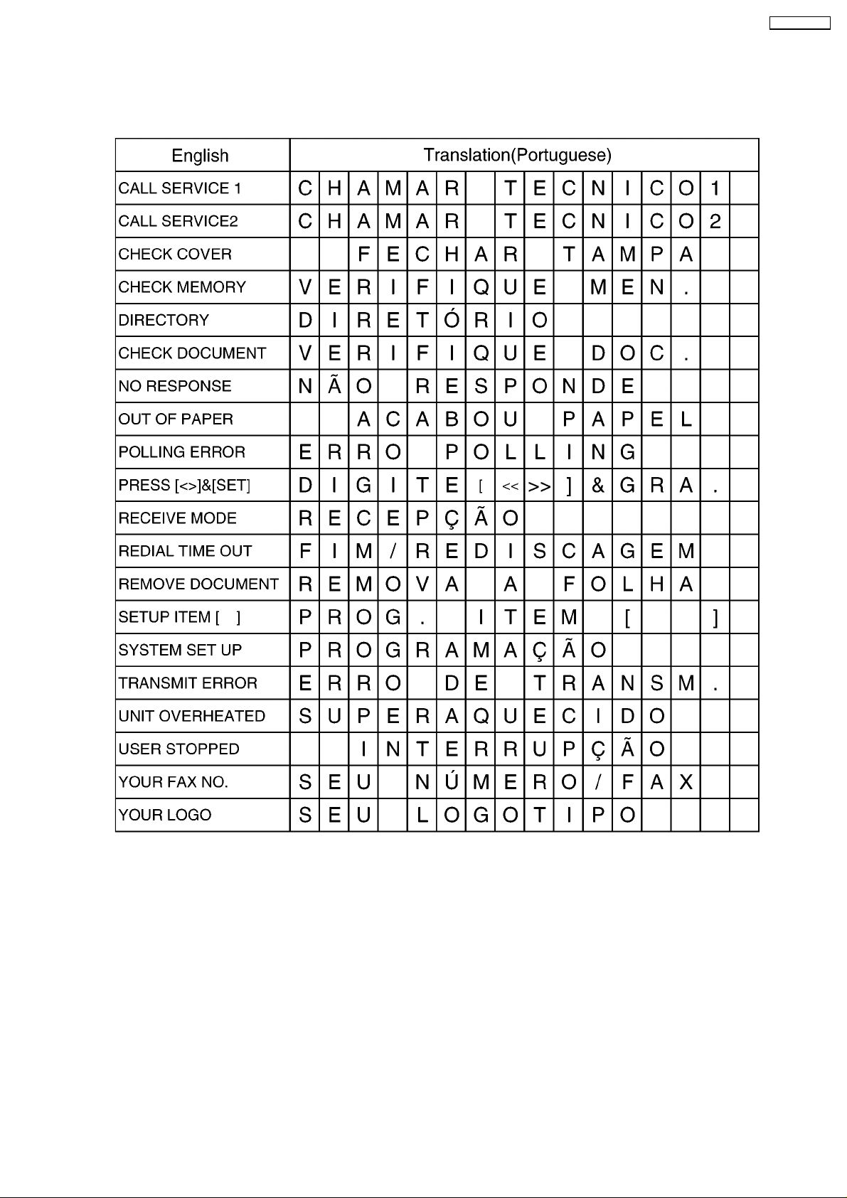
1.1. LCD MESSAGE
KX-FT72BR-G
3
KX-FT72BR-G
1.2. SAFETY PRECAUTIONS
1. Before servicing, unplug the AC power cord to prevent an electric shock.
2. When replacing parts, use only the manufacturer´s recommended components.
3. Check the condition of the power cord. Replace if wear or damage is evident.
4. After servicing, be sure to restore the lead dress, insulation barriers, insulation papers, shields, etc.
5. Before returning the serviced equipment to the customer, be sure to perform the following insulation resistance test to prevent
the customer from being exposed to shock hazards.
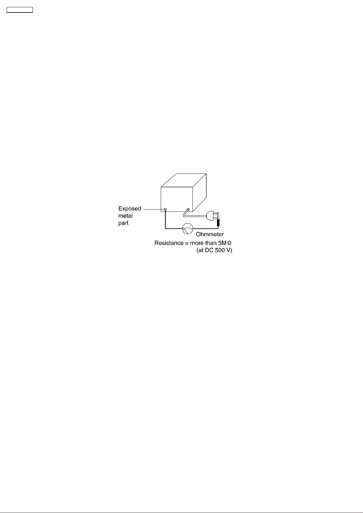
1.3. INSULATION RESISTANCE TEST
1. Unplug the power cord and short the two prongs of the plug with a jumper wire.
2. Turn on the power switch.
3. Measure the resistance value with an ohmmeter between the jumpered AC plug and each exposed metal cabinet part (screw
heads, control shafts, bottom frame, etc.).
Note: Some exposed parts may be isolated from the chassis by design. These will read infinity.
4. If the measurement is outside the specified limits, there is a possibility of a shock hazard.
The equipment should be repaired and rechecked before it is returned to the customer.
1.4. FOR SERVICE TECHNICIANS
ICs and LSIs are vulnerable to static electricity.
When repairing, the following precautions will help prevent recurring malfunctions.
1. Cover the plastic part´s boxes with aluminum foil.
2. Ground the soldering irons.
3. Use a conductive mat on the worktable.
4. Do not touch the IC or LSI pins with bare fingers.
1.5. BATTERY CAUTION
CAUTION
Danger of explosion if the battery is replaced incorrectly. Replace only with the same or equivalent type recommended by the
manufacturer. Discard used batteries according to following caution:
Disposal of lithium batteries should be performed by permitted, professional disposal firms knowledgeable in state government
federal and local hazardous materials and hazardous waste transportation and disposal requirements.
A battery continues to have no transportation limitations as long as it is separated to prevent short circuits and packed in strong
packaging.
Commercial firms that dispose of any quantity of lithium cells should have a mechanism in place to account for their ultimate
disposition. This is a good practice for all types of commercial or industrial waste.
Recommend Type Number:
PFSU1004Z (BAT501) Manufactured by TOSHIBA
CR2032 (BAT501) Manufactured by MATSUSHITA
PQPCR2032H09 (BAT501) Manufactured by SONY
4
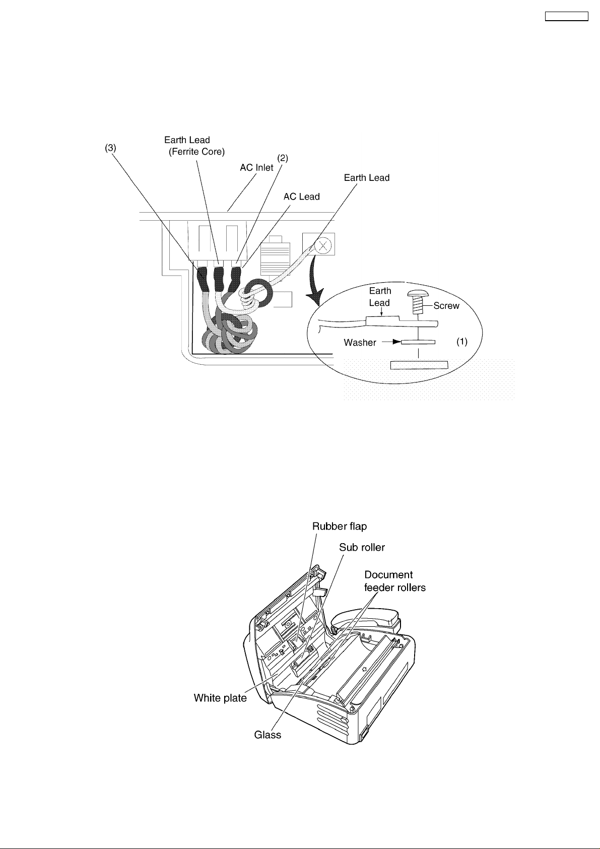
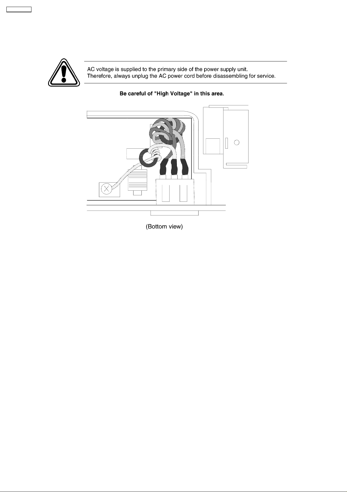
1.6. AC CAUTION
For safety, before closing the lower cabinet, please make sure of the following precautions.
(1) The earth lead is fixed with the screw.
(2) The AC connector is connected properly.
(3) Wrap the Earth Lead lead around the core 4 times.
KX-FT72BR-G
1.7. PERSONAL SAFETY PRECAUTIONS
1.7.1. MOVING SECTIONS OF THE UNIT
Be careful not to let your hair, clothes, fingers, accessories, etc., become caught in any moving sections of the unit.
The moving sections of the unit are the rollers and a gear. There is a separation roller and a document feed roller which are rotated
by the document feed motor. A gear rotates the two rollers. Be careful not to touch them with your hands, especially when the unit
is operating.
5
KX-FT72BR-G
1.7.2. LIVE ELECTRICAL SECTIONS
All the electrical sections of the unit supplied with AC power by the AC power cord are live.
Never disassemble the unit for service with the AC power supply plugged in.
1.8. FEATURES
General
• • Help function
Please refer to WHEN YOU DON´T KNOW HOW TO
OPERATE THE UNIT, USE THE HELP FUNCTION.(P.21)
to print below features.
Display:(Refer to LCD MESSAGE (P.3))
− − DIRECTORY
− − RECEIVE MODE
Facsimile
• • Space Saving Compact Design
• • Resolution: Standard, Fine/Photo, Super Fine
• • Copier Function
• • Automatic Document Feeder (10 Sheets)
• • Help Printout
• • Easy-to-view LCD (15 Characters)
Integrated Telephone System
• • Electric Volume Control
• • On-hook dialing
• • Redialing function
• • Temporary tone dialing
• • Electric Telephone directory
6

KX-FT72BR-G
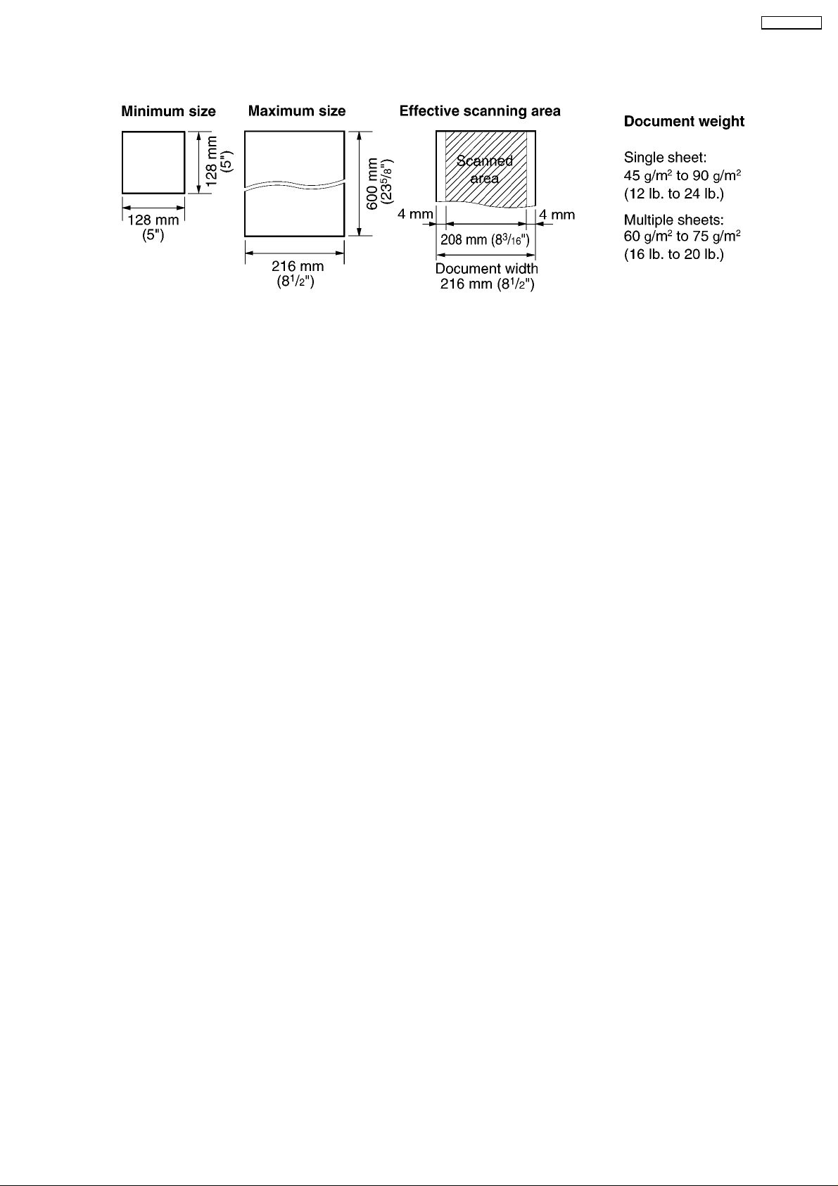
1.9. SPECIFICATIONS
Applicable Lines: Public Switched Telephone Network
Document Size: Max. 216 mm (8 1/2”) in width
Max. 600 mm (23 5/8”) in length
Effective Scanning Width: 208mm (8 3/16”)
Recording Paper Size: 216 mm max. 30 m (8 1/2”×98”) roll
Effective Printing Width: 208 mm (8 3/16”)
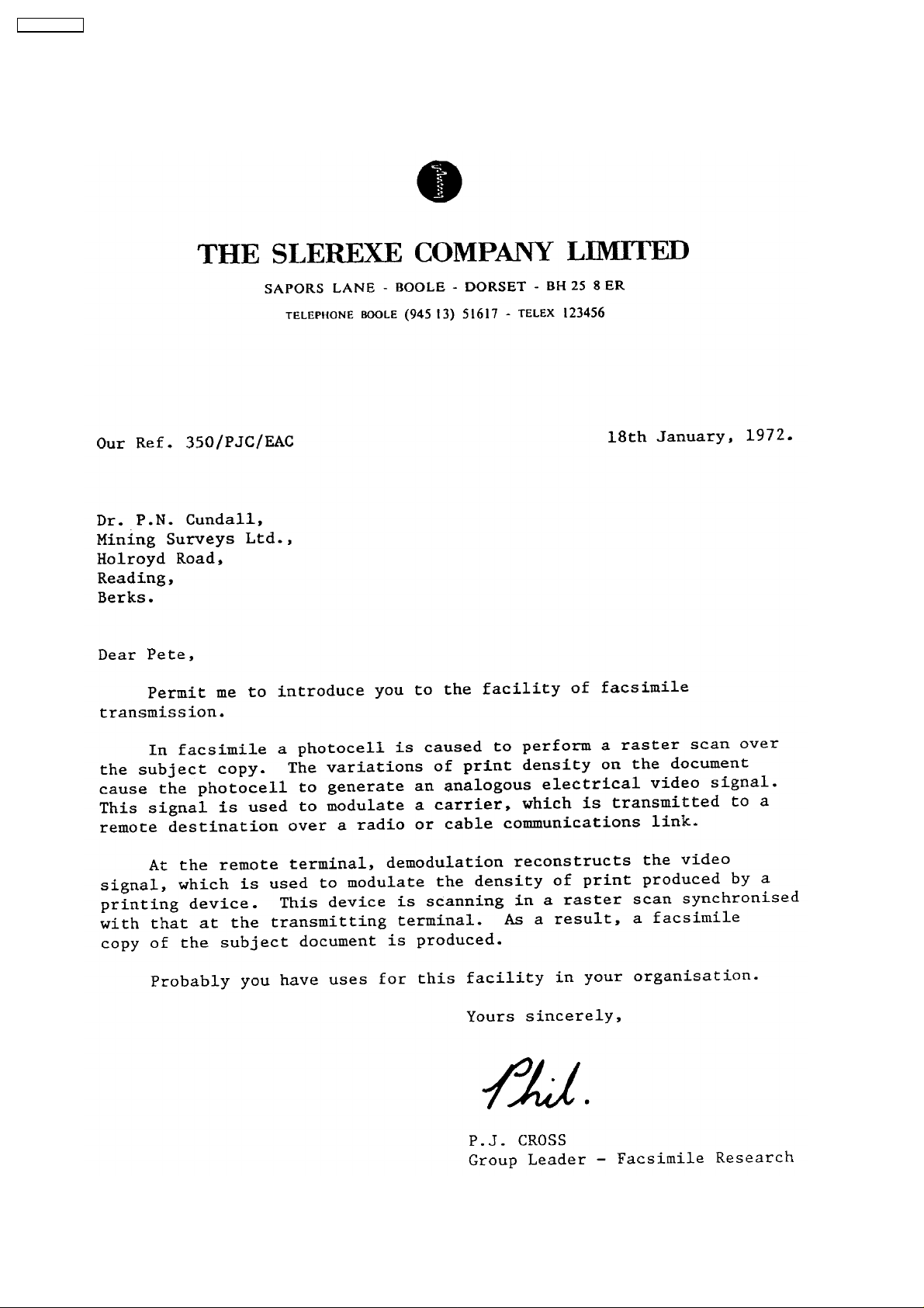
Transmission Time*: Approx. 15 s/page (Original mode)**
Approx. 30 s/page (G3 Normal mode)
Scanning Density: Horizontal:
8 pels/mm (203 pels/inch)
Vertical:
3.85 lines/mm (98 lines/inch)—STANDARD
7.7 lines/mm (196 lines/inch)—FINE/PHOTO
15.4 lines/mm (392 lines/inch)—SUPER FINE
Halftone Level: 64-level
Scanner Type: Contact Image Sensor (CIS)
Printer Type: Thermal Printing
Data Compression System: Modified Huffman (MH), Modified READ (MR)
Modem Speed: 9,600 / 7,200 / 4,800 / 2,400 bps; Automatic Fallback
Operating Environment: 5°C—35°C (41°F—95°F), 45 %—85 % RH (Relative Humidity)
Dimensions (H×W×D): 118 mm × 338 mm × 246 mm (4 5/8” × 13 5/16” × 9 11/16”)
Mass (Weight): Approx. 2.5 kg (5.5 lb.)
Power Consumption: Standby: Approx. 5.5 W
Transmission: Approx. 20 W (When sending the ITU-T No.1 Test Chart)
Reception: Approx. 33 W (When receiving the ITU-T No. 1 Test Chart)
Copy: Approx. 30 W (When copying the ITU-T No. 1 Test Chart)
Maximum: Approx. 120 W (When copying a 100 % black document)
Power Supply: 120 V AC, 60 Hz
* Transmission speed depends upon the contents of the pages, resolution, telephone line conditions and capability of the other
party´s machine.
** Transmission speed is based upon the ITU-T No. 1 Test Chart and original mode. (Refer to TEST CHART (P.8).)
If the capability of the other party’s machine is inferior to your unit, the transmission time may be longer.
Note:
• • Any details given in these instructions are subject to change without notice.
• • The pictures and illustrations in these instructions may vary slightly from the actual product.
1.10. OPTIONAL ACCESSORY
Model No. Description Specifications
KX-A106 Standard thermal recording paper 216 mm × 30 m (8 1/2”×98’) roll, with 25 mm (1”) core
7
KX-FT72BR-G
1.11. TEST CHART
1.11.1. ITU-T NO.1 TEST CHART
8
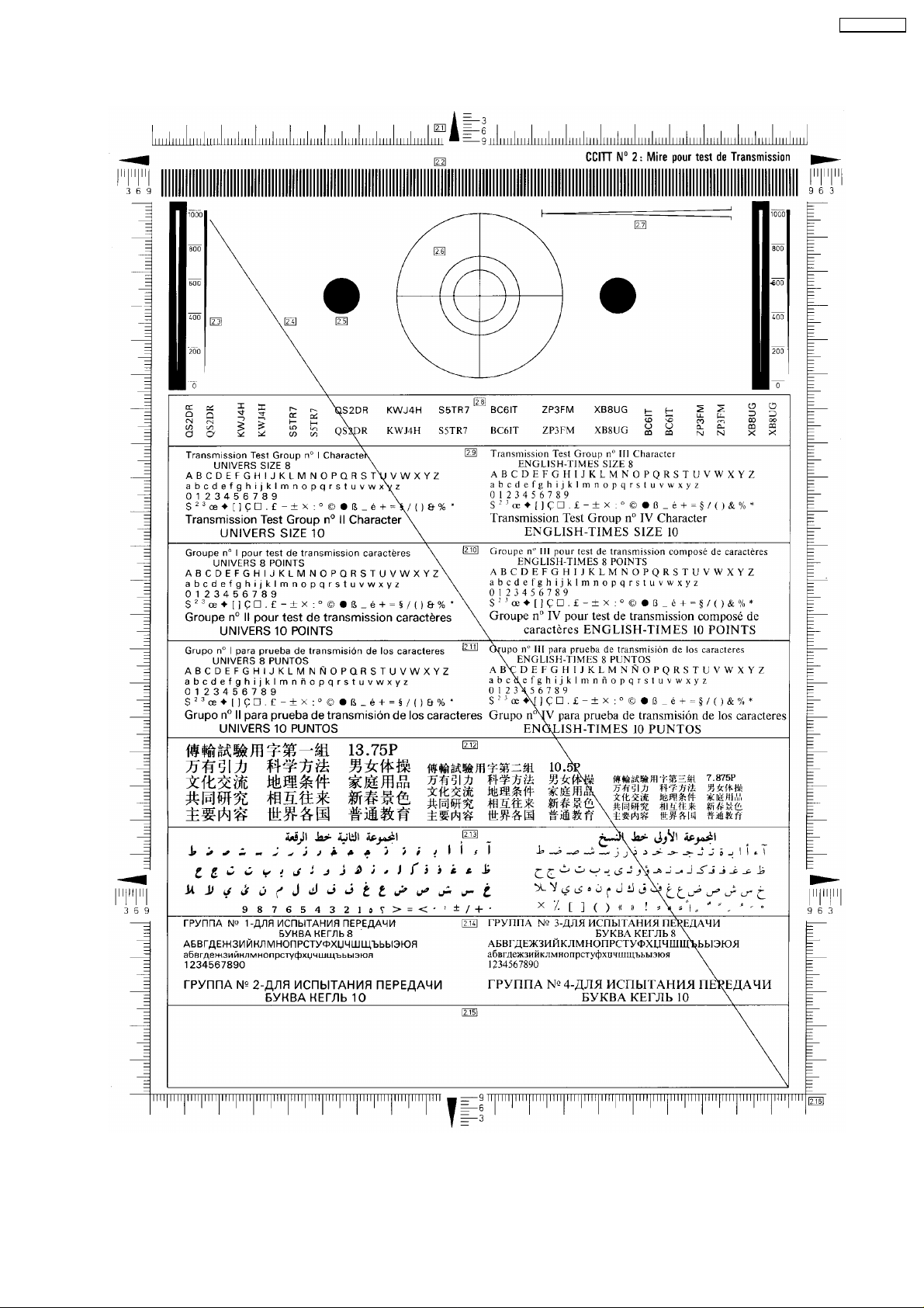
1.11.2. CCITT NO. 2 TEST CHART
KX-FT72BR-G
9
KX-FT72BR-G
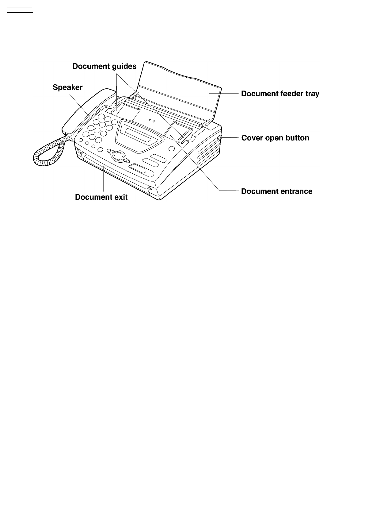
1.12. LOCATION OF CONTROLS
1.12.1. OVERVIEW
10
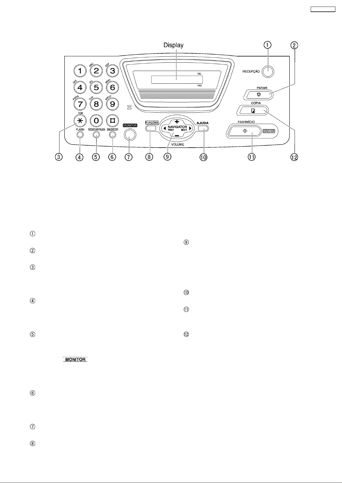
1.12.2. CONTROL PANEL
KX-FT72BR-G
RECEIVE MODE
• • To change the receive mode.
STOP
• • To stop an operation or cancel programming.
TONE
• • To change from pulse to tone
temporarily during dialing when your
line has rotary pulse services.
FLASH
• • To access special telephone services
such as call waiting or for transferring
extension calls.
REDIAL/PAUSE
• • To redial the last number dialed. If the
line is busy when you make a phone call
using the
automatically redial the number up to 5
times.
• • To insert a pause during dialing.
MUTE
• • To mute your voice to the other party
during a conversation. Press this button
again to resume the conversation.
MONITOR
• • To dial without lifting the handset.
MENU
button, the unit will
• • To initiate or exit programming .
NAVIGATOR, VOLUME
• • To adjust volume.
• • To search for a stored name.
• • To select the features or feature settings
during programming.
• • To navigate to the next operation.
HELP
• • To print a quick reference.
FAX/START, SET
• • To initiate fax transmission or reception.
• • To store a setting during programming.
COPY
• • To initiate copying.
11
KX-FT72BR-G
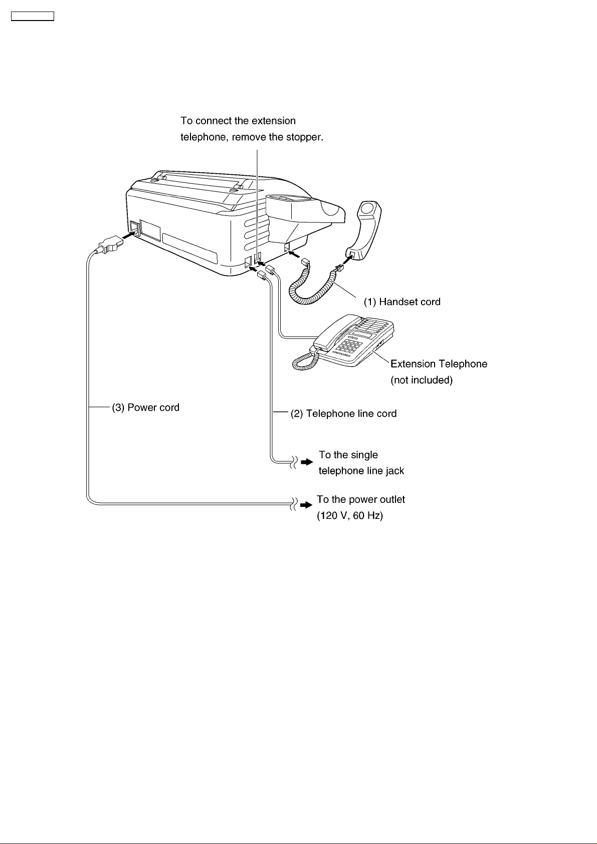
1.13. CONNECTIONS
(1) Connect the handset cord.
(2) Connect the telephone line cord.
(3) Connect the power cord.
NOTE
When you operate this products, the power outlet should be near the product and easily accessible.
12
1.14. INSTALLATION
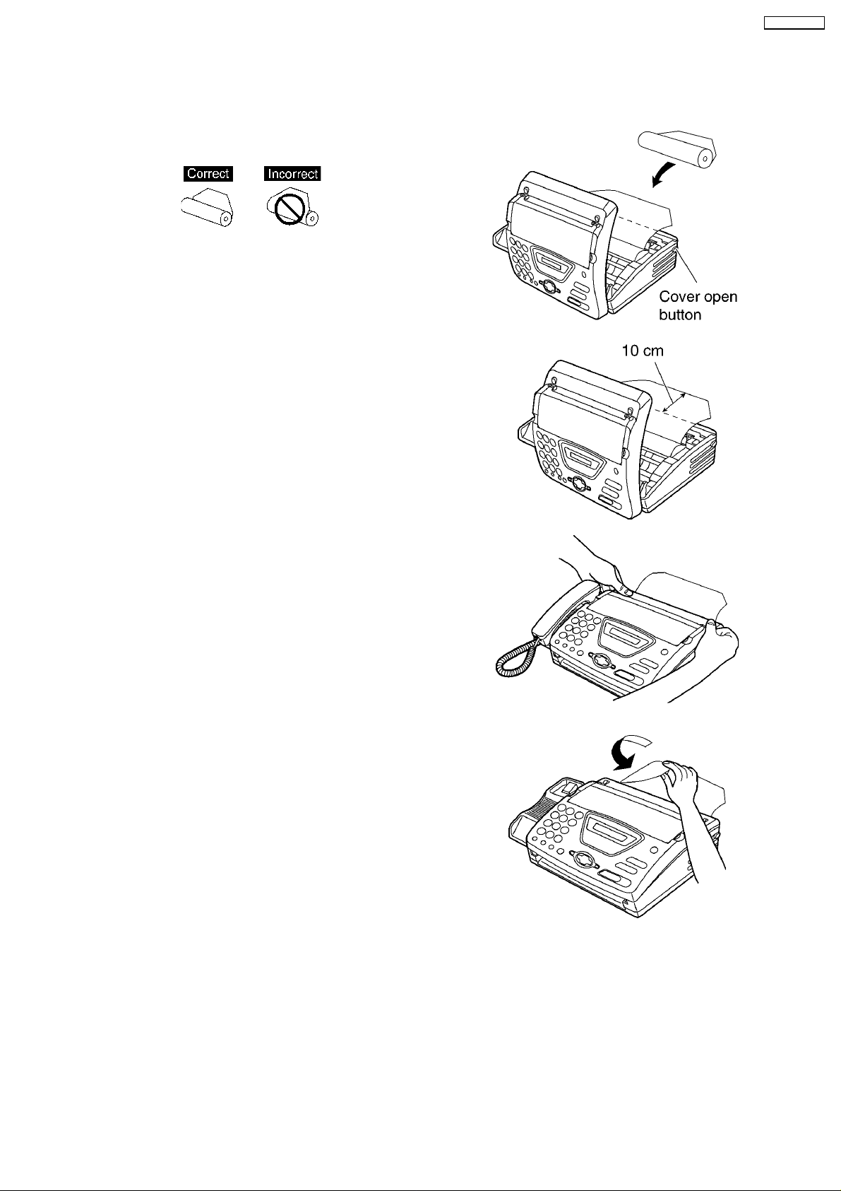
1.14.1. INSTALLING THE RECORDING PAPER
(1) Open the cover by pressing the cover open button and
install the recording paper roll.
• • If the paper is secured with glue or tape, cut
approximately 15 cm (6 inches) from the beginning
of the roll.
(2) Pull the leading edge of the paper approximately 10 cm
(4 inches) out of the unit.
• • Make sure that there is no slack in the paper roll.
KX-FT72BR-G
(3) Close the cover securely by pushing down on both
sides.
(4) Tear off the excess paper by pulling it towards you.
Note:
• • Only use the included roll of paper or specified recording paper, or else the print quality may be affected and/or excessive
thermal head wear may occur.
• • To order recording paper, see OPTIONAL ACCESSORY (P.7).
• • When the power cord is connected, every time you close the cover a message will be printed if the recording paper is set
to the wrong side, a message will not be printed. Install the paper correctly.
13
KX-FT72BR-G
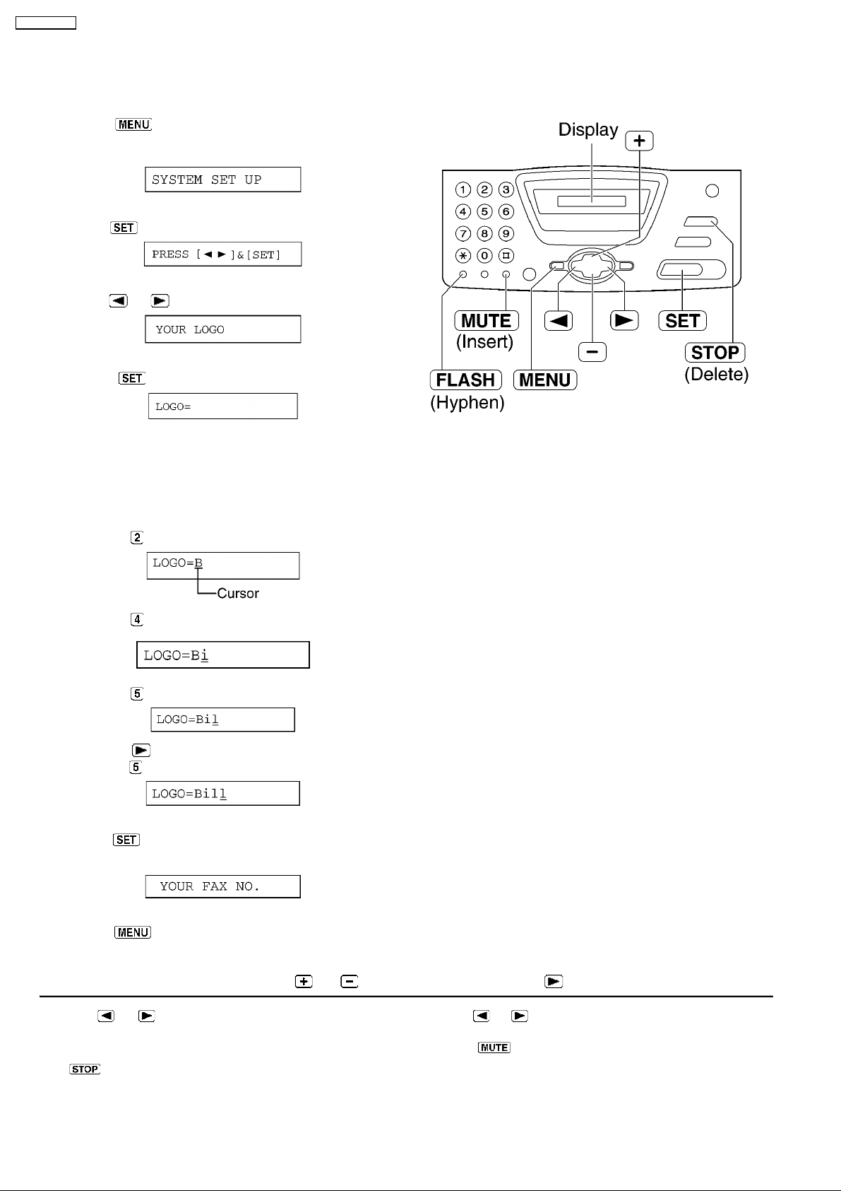
1.14.2. SETTING YOUR LOGO
The logo can be your company, division or name.
(1) Press
Display:Refer to LCD MESSAGE (P.3)
(2) Press .
(3) Press or until the following is displayed.
(4) Press .
.
(5) Enter your logo, up to 30 characters, by using the dial
keypad.
Example: Bill
a. Press
2 times.
b. Press 6 times.
c. Press 6 times.
d. Press to move the cursor to the next space and
press
6 times.
(6) Press .
• • The next feature will be displayed.
(7) Press .
Note:
• • You can enter your logo by pressing
To correct a mistake
• • Press
and make the correction.
To delete a character
• • Move the cursor to the character you want to delete and press
or to move the cursor to the incorrect character,
.
or in step (4). In this case, press to move the cursor.
To insert a character
1. Press
where you want to insert the character.
2. Press
or to move the cursor to the position to the right of
to insert a space and enter the character.
14
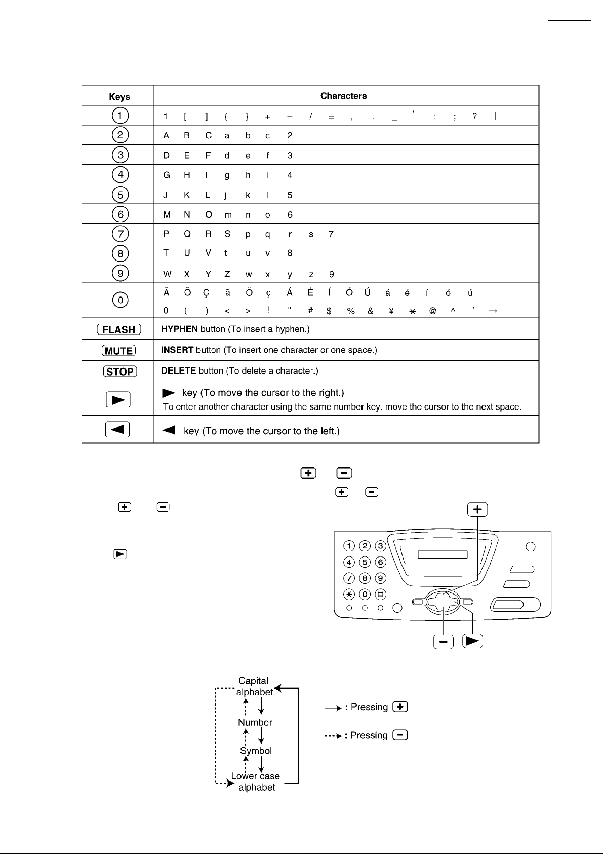
1.14.3. TO SELECT CHARACTERS WITH THE DIAL KEYPAD
Pressing the dial keys will select a character as shown below.
KX-FT72BR-G
1.14.4. TO SELECT CHARACTERS USING or
Instead of pressing the dial keys, you can select characters using or .
(1) Press
displayed.
(2) Press
• • The character displayed in step 1 is inserted.
(3) Return to step 1 to enter the next character.
Display order of characters
or until the desired character is
to move the cursor to the next space.
15
KX-FT72BR-G
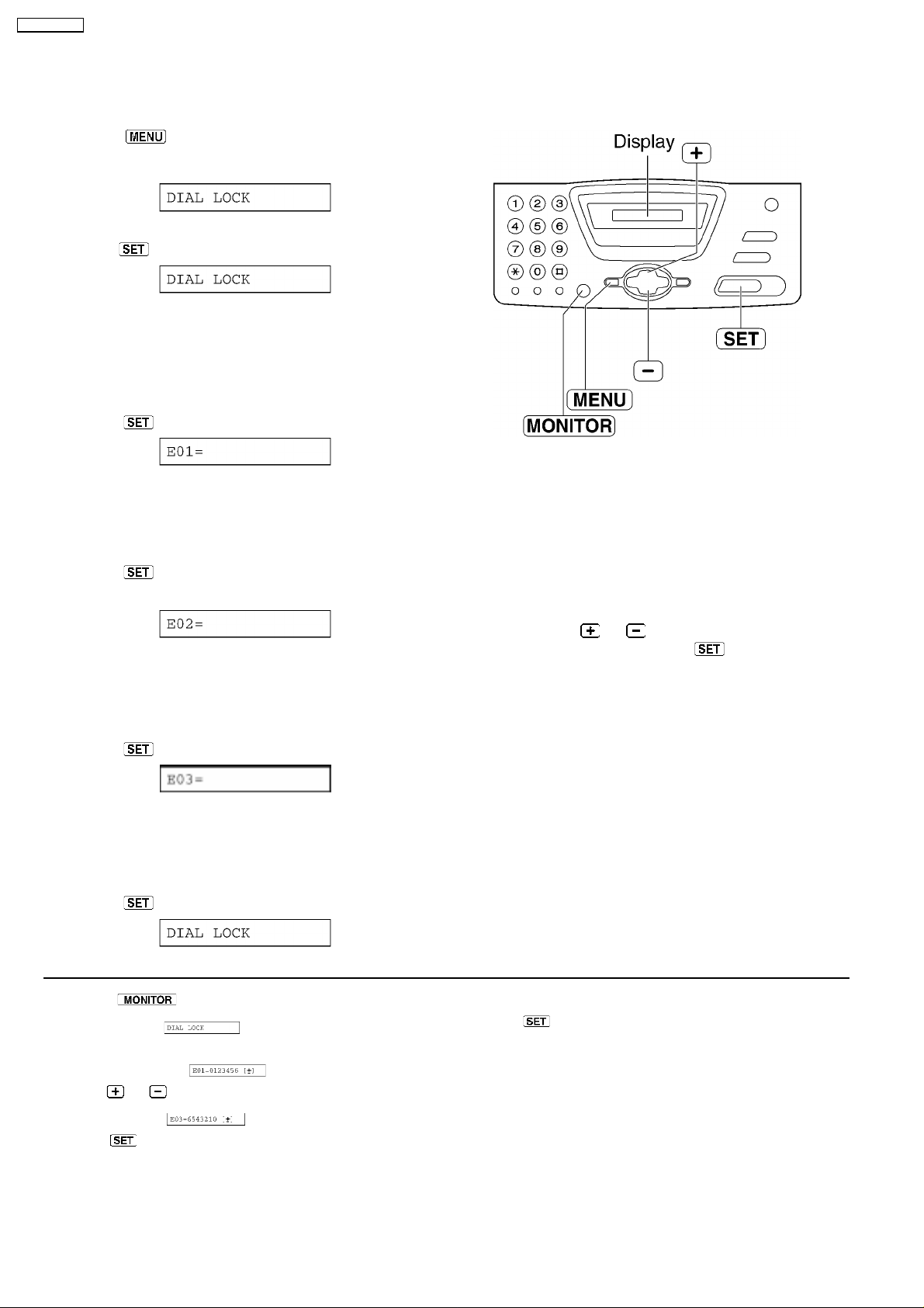
1.14.5. SETTING THE DIAL LOCK
The dial lock feature prevents the unit from calls being made to any numbers, except for pre-stored emergency telephone numbers.
(1) Press
Display:
(2) Press .
(3) Enter yor PIN(Personal dentification Number) code, from 2
to 4 digits, using 0-9.
If you want to release the PIN code, refer to #531 on the
SERVICE FUNCTION TABLE (P.77)
.
(4) Press
.
(5) Enter an emergency telephone number, up to 30 digits,
using the dial keypad.
(6) Press
.
• • The next feature will be displayed.
(7) If necessary, enter the second emergency telephone
number using the dial keypad.
• • If you do not need to enter, skip to step 8.
(8) Press
.
(9) If necessary, enter the third emergency telephone number
using the dial keypad.
• • If you do not need to enter, skip to step 10.
Note:
• • To correct/delete an emergency
telephone number, see the bottom right
of page 19.
• • You can also enter an emergency
telephone number using the directory in
steps 5,7 and 9.
Press
or until the desired name
is displayed, then press
.
(10) Press
Making an emergency call
1. Press
following.
Display:
• • The display will show the following.
Example:
2. Press or unitil the desired emergency telephone number
is displayed.
Example:
3. Press
• • The unit will start dialing automatically.
• • If any documents are in the document entrance, the unit will
start fax transmission..
.
to lift the handset while the unit displays the
To insert a character
1. Follow steps 1-3 on the left.
2. Press
.
16
1.14.6. DOCUMENTS YOU CAN SEND
Note:
• • Remove clips, staples or other similar fasteners.
• • Check that ink, paste or correction fluid has dried.
• • Do not send the following types of documents:(Use copies for fax transmission.)
— Chemically treated paper such as carbon or carbonless duplicating paper
— Electrostatically charged paper
— Badly curled, creased or torn paper
— Paper with a coated surface
— Paper with a faint image
— Paper with printing on the opposite side that can be seen through the front (i.e. newspaper)
• • To transmit the document(s) with a width of less than A4 size (210mm), we recommend using a
copy machine to copy the original document onto A4 or letter-sized paper, than transmit the copied
document.
KX-FT72BR-G
17
KX-FT72BR-G
1.15. MAINTENANCE ITEMS AND COMPONENT LOCATIONS
1.15.1. OUTLINE
MAINTENANCE AND REPAIRS ARE PERFORMED USING THE FOLLOWING STEPS.
1. Periodic maintenance
Inspect the equipment periodically and if necessary, clean any contaminated parts.
2. Check for breakdowns
Look for problems and consider how they arose.
If the equipment can be still used, perform copying, self testing or communication testing.
3. Check equipment
Perform copying, self testing and communication testing to determine if the problem originates from the transmitter, receiver or
the telephone line.
4. Determine causes
Determine the causes of equipment problem by troubleshooting.
5. Equipment repairs
Repair or replace the defective parts and take appropriate measures at this stage to ensure that the problem will not recur.
6. Confirm normal operation of the equipment
After completing the repairs, conduct copying, self testing and communication testing to confirm that the equipment operates
normally.
7. Record keeping
Make a record of the measures taken to rectify the problem for future reference.
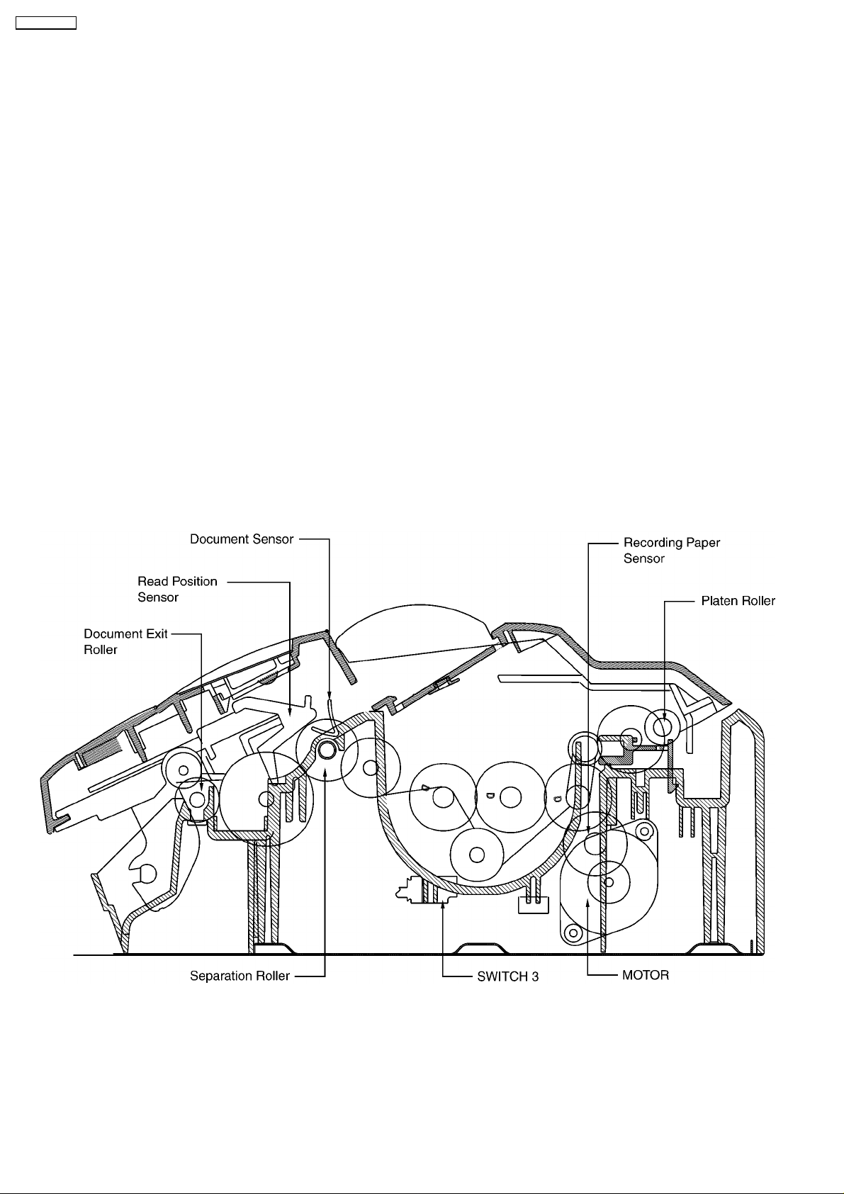
1.15.2. MAINTENANCE CHECK ITEMS/COMPONENT LOCATIONS
18
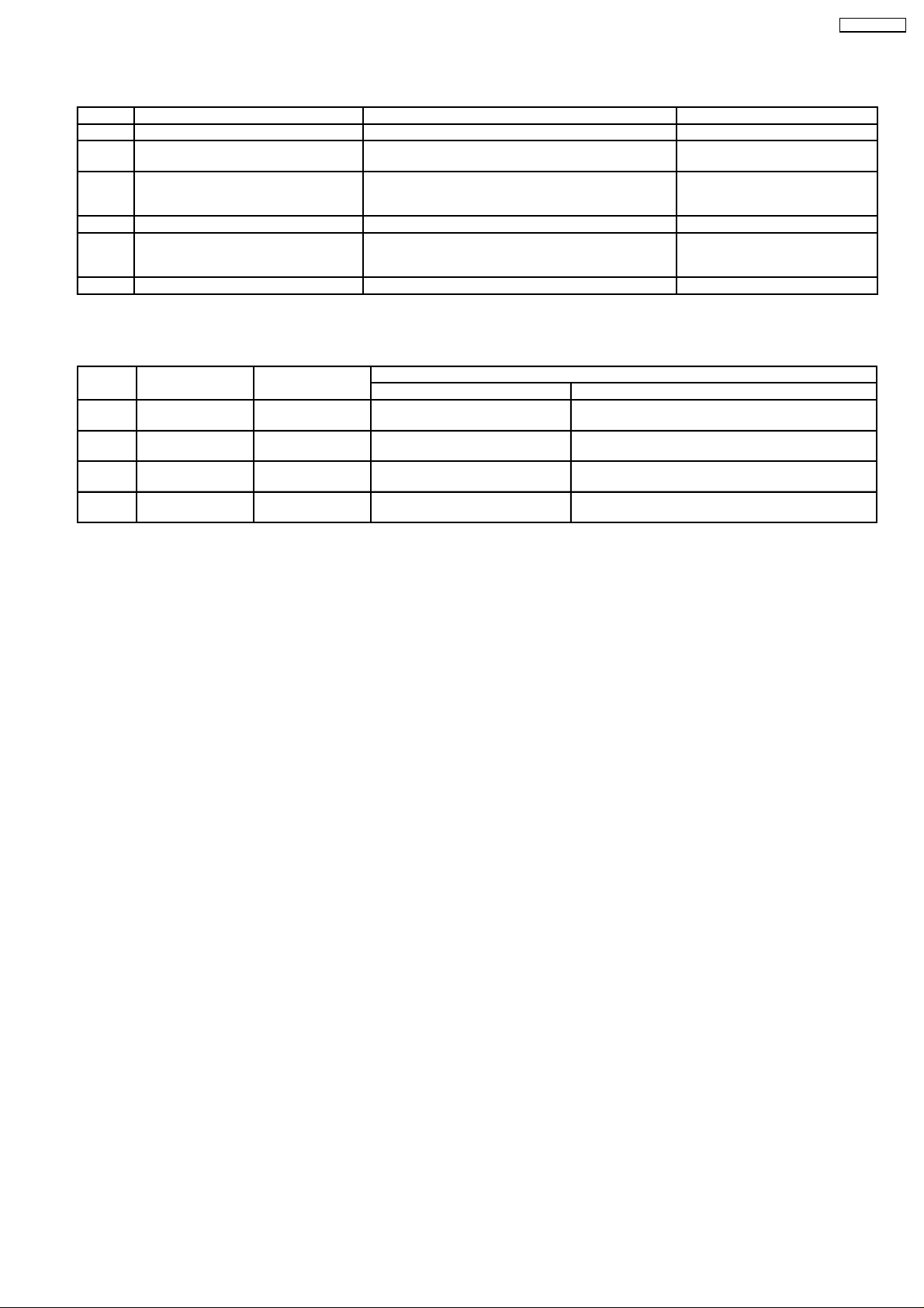
1.15.2.1. MAINTENANCE LIST
NO. OPERATION CHECK REMARKS
1 Document Path Remove any foreign matter such as paper. —
2 Rollers If the roller is dirty, clean it with a damp cloth then dry
thoroughly.
3 Thermal Head If the thermal head is dirty, clean the printing surface
with a cloth moistened with denatured alcohol (alcohol
without water), then dry thoroughly.
4 Glass If the glass is dirty, clean the with a dry soft cloth. See CLEANING (P.20)
5 Sensors Document sensor (PS1), Read position sensor (PS2),
Recording paper/cover open sensor (SW1) Jam sensor
(SW3).
6 Abnormal, wear and tear or loose parts If the glass is dirty, clean them with a dry soft cloth. —
See CLEANING (P.20)
See CLEANING (P.20) and
DISASSEMBLY INSTRUCTIONS
(P.84).
See SENSOR SECTION (P.72)
and SENSORS AND SWITCHES
(P.118) .
1.15.2.2. MAINTENANCE CYCLE
No. Item Cleaning Cycle Replacement
Cycle Procedure
1 Separation Roller
(Ref. No. 72)
2 Separation Rubber
(Ref. No. 21)
3 Feed Rollers
(Ref. No. 58)
4 Thermal Head
(Ref. No. 53)
* These values are standard and may vary depending on usage conditions.P.89
3 months 7 years*
(100,000 documents)
3 months 7 years*
(100,000 documents)
3 months 7 years*
(100,000 documents)
3 months 7 years*
(100,000 documents)
See HOW•@TO REMOVE THE MOTOR BLOCK
AND SEPARATION ROLLER (P.89).
See HOW•@TO REMOVE THE MOTOR BLOCK
AND SEPARATION ROLLER (P.89).
See HOW•@TO REMOVE THE MOTOR BLOCK
AND SEPARATION ROLLER (P.89).
See HOW•@TO REMOVE THE MOTOR BLOCK
AND SEPARATION ROLLER (P.89).
KX-FT72BR-G
19
KX-FT72BR-G
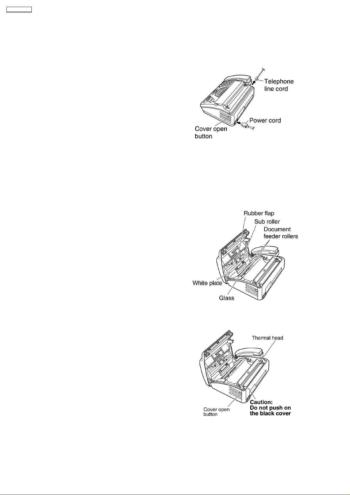
1.15.3. CLEANING
1.15.3.1. DOCUMENT FEEDER
If misfeeding occurs frequently or if dirty patterns or black bands or white bands appear on a copied or transmitted document
or the original of a copied document, clean the document feeder.
(1) Disconnect the power cord and the telephone line cord.
(2) Open the cover by pressing the cover open button.
(3) Clean the document feeder rollers, sub roller and
rubber flap with a cloth moistened with isopropyl rubbing
alcohol, and let all parts dry thoroughly.
(4) Clean the white plate and glass with a soft dry cloth.
(5) Close the cover securely by pushing down on both
ends.
(6) Connect the power cord and the telephone line cord.
Caution:
Do not use paper products, such as paper towels or
tissues, to clean the inside of the unit.
1.15.3.2. THE THERMAL HEAD
If dirty patterns or black bands appear on a copied or received document, clean the thermal head.
(1) Disconnect the power cord and the telephone line cord.
(2) Open the cover by pressing the cover open button.
(3) Clean the thermal head with a cloth moistened with
isopropyl rubbing alcohol, and let it dry thoroughly.
(4) Close the cover securely by pushing down on both
sides.
(5) Connect the power cord and the telephone line cord.
Caution:
To prevent a malfunction due to static electricity, do
not use a dry cloth and do not touch the thermal
head directly.
20
KX-FT72BR-G
2 TROUBLESHOOTING GUIDE
2.1. TROUBLESHOOTING SUMMARY
2.1.1. TROUBLESHOOTING
After confirming the problem by asking the user, troubleshoot according to the instructions and observe the following precautions.
2.1.2. PRECAUTIONS
1. If there is a problem with the print quality or the paper feed, first check if the installation space and the print paper meets the
specifications, the paper selection lever/paper thickness lever is set correctly, and the paper is set correctly without any slack.
2. Before troubleshooting, first check that the connectors and cables are connected correctly (not loose).
If the problem occurs randomly, check it very carefully.
3. When connecting the ACpower cord with theunit case and checking the operation, exercise utmost care when handling electric
parts in order to avoid electric shocks and short-circuits.
4. After troubleshooting, double check that you have not forgotten any connectors, left any loose screws, etc.
5. Always test to verify that the unit is working normally.
2.1.3. WHEN YOU DON´T KNOW HOW TO OPERATE THE UNIT, USE THE HELP
FUNCTION
• • How to use:
1. press
2. press
3. press
.
or until the desired item is displayed.
.
21
KX-FT72BR-G
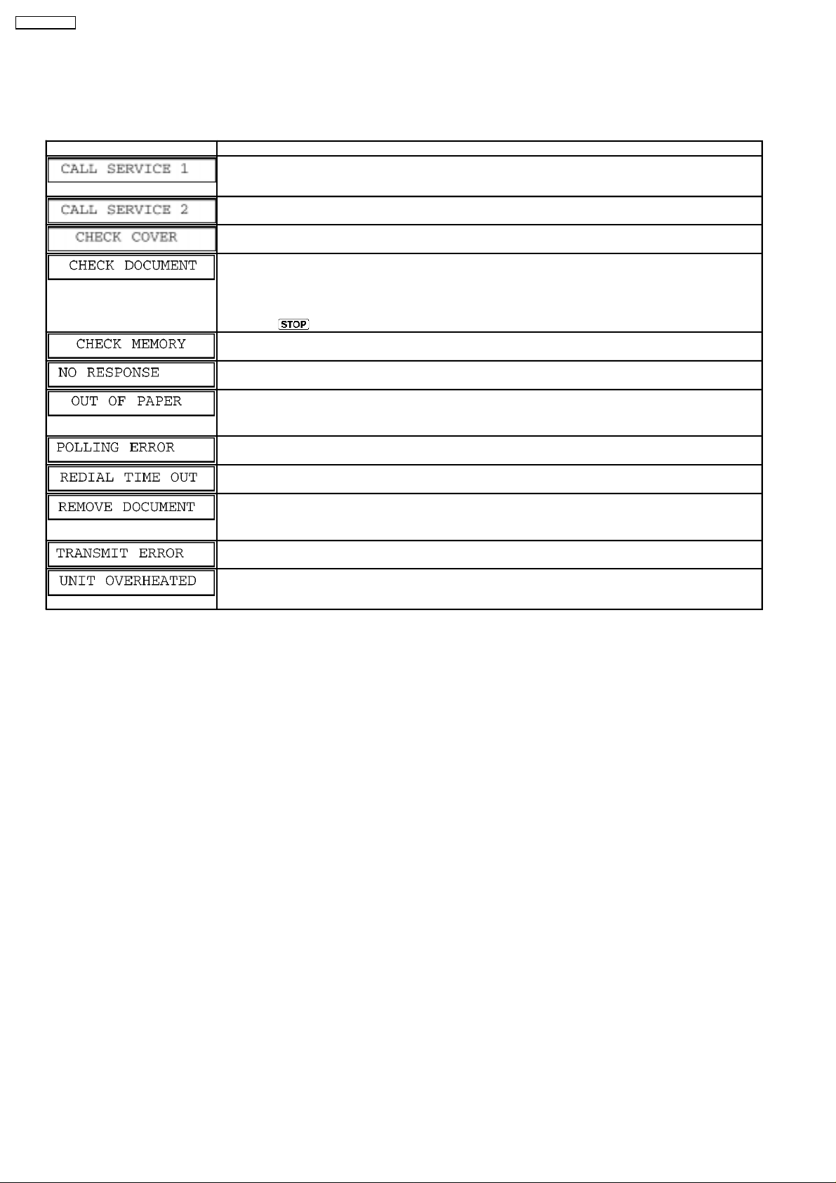
2.2. USER RECOVERABLE ERRORS
If the unit detects a problem, the following messages will appear on the display.
Refer to LCD MESSAGE (P.3)
DISPLAY MESSAGE CAUSE AND SOLUTION
• • There is something wrong with the unit. Contact our service personnel.
[This error is displayed when the thermal head does not warm up. Check the thermistor on the thermal
head and connector lead.]
• • This message appears when the gear is not in an idle state. Check the GEAR BLOCK.
• • The cover is open. Close it.
• • The document was not fed into the unit properly. Reinsert the document. If misfeeding occurs frequently,
clean the document feeder rollers (Refer to DOCUMENT FEEDER (P.20)) and try again. (Refer to
DOCUMENT JAM (P.23).)
• • Attempted to transmit a document longer than 600 mm.
Press
• • Memory (telephone numbers, parameters, etc.) has been erased. Re-program.
[ The backup battery on the top of the digital board may be low or dead, so check it. ]
• • The other part’y fax machine is busy or has run out of recording paper. Try again.
• • The unit has run out of recording paper. Install a recording paper roll.
(Refer to INSTALLING THE RECORDING PAPER (P.13).)
to remove the document. Divide the document into two or more sheets and try again.
• • The other part’y fax machine dose not provide the polling function. Check with the other party.
• • The other part’y fax machine is busy or has run out of recording paper. Try again.
• • The document is jammed. Remove the jammed document.
• • [Alternately, turn off service code #559 to enable sending of documents longer than 600 mm] (Refer to
DOCUMENT JAMS (SENDING) (P.23).)
• • A transmission error occurred. Try again.
• • The unit is too hot. Let the unit cool down.
[ If many copies are nearly all black, this message will be displayed. When this occure, open the front
cover and let the unit cool down.]
Notes: The explanations given in the [ ] are for servicemen only.
22
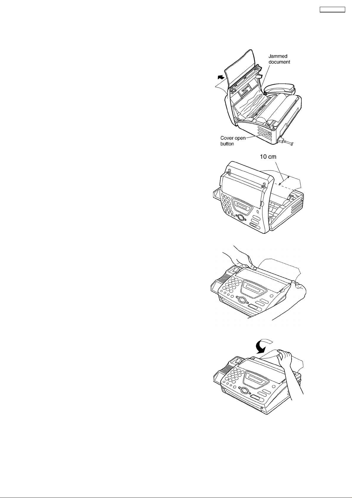
2.2.1. DOCUMENT JAMS (SENDING)
If the unit does not release the document during feeding, remove the jammed document as follows.
(1) Open the cover by pressing the cover open button.
(2) Remove the jammed document carefully.
(3) Pull the leading edge of the recording paper
approximately 10 cm (4 inches) out of the unit.
• • Make sure that there is no slack in the paper roll.
KX-FT72BR-G
(4) Close the cover securely by pushing down on both
sides.
(5) Tear off the excess paper by pulling it towards you.
Note:
• • Do not pull out the jammed document forcibly before opening the cover.
23
KX-FT72BR-G
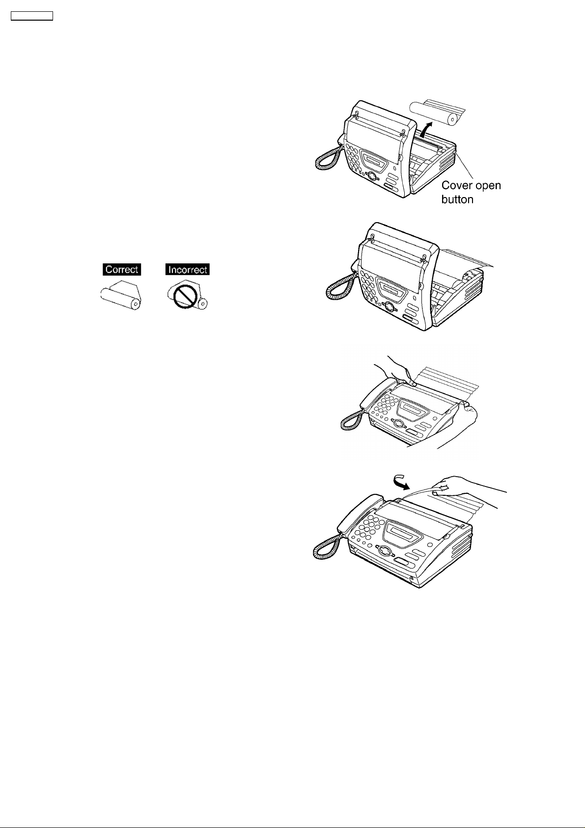
2.2.2. RECORDING PAPER JAM
If the unit dose not eject any recording paper during fax reception or copying, the recording paper has jammed. Remove the
jammed paper as shown below.
(1) Open the cover by pressing the cover open button and
remove the recording paper roll.
(2) Replace the recording paper roll in the proper direction,
and pull the leading edge of the paper approximately 10
cm (4 inches) out of the unit.
• • Make sure that there is no slack in the paper roll.
(3) Close the cover securely by pushing down on both
sides.
(4) Tear off the excess paper by pulling it towards you.
Note:
• • When the power cord is connected, every time you close the cover a message will be printed. If the recording paper is set
to the wrong side, a message will not be printed. Install the paper correctly.
24
KX-FT72BR-G
2.3. TROUBLESHOOTING DETAILS
2.3.1. OUTLINE
Troubleshooting guide provides a logical path of deduction to assist in locating a fault and suggests methods of restoring the unit
to full working condition. Use the reported symptoms of the fault to determine the best troubleshooting method. Even difficult faults
can be tracked to a specific block or area, for example, the "Digital Board" or "Image Sensor".
A variety of fault descriptions from customers often point to the same area and, for this reason, careful analysis of the reported
symptoms is required. After every repair, test all functions to ensure no problems are evident.
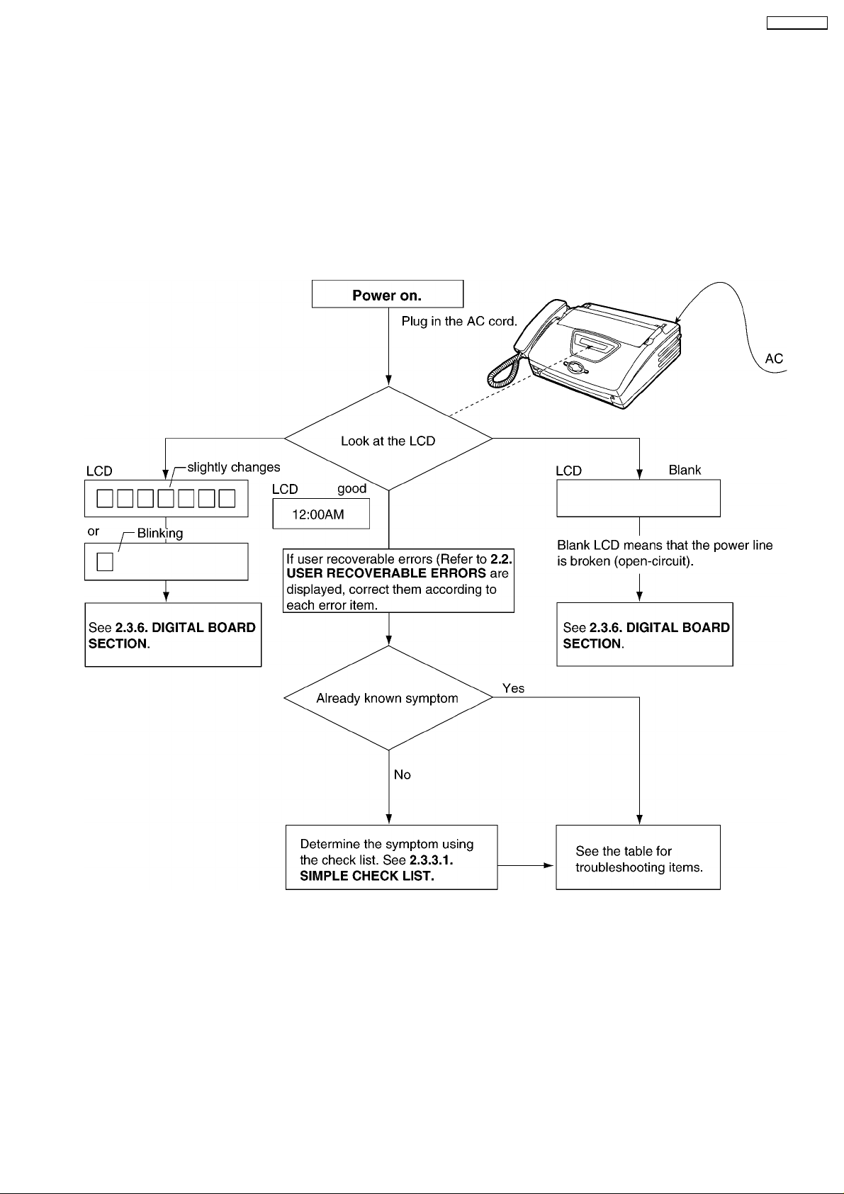
2.3.2. STARTING TROUBLESHOOTING
Select the appropriate troubleshooting method according to the symptoms.
CROSS REFERENCE:
USER RECOVERABLE ERRORS (P.22)
SIMPLE CHECK LIST (P.26)
DIGITAL BOARD SECTION (P.56)
25
KX-FT72BR-G
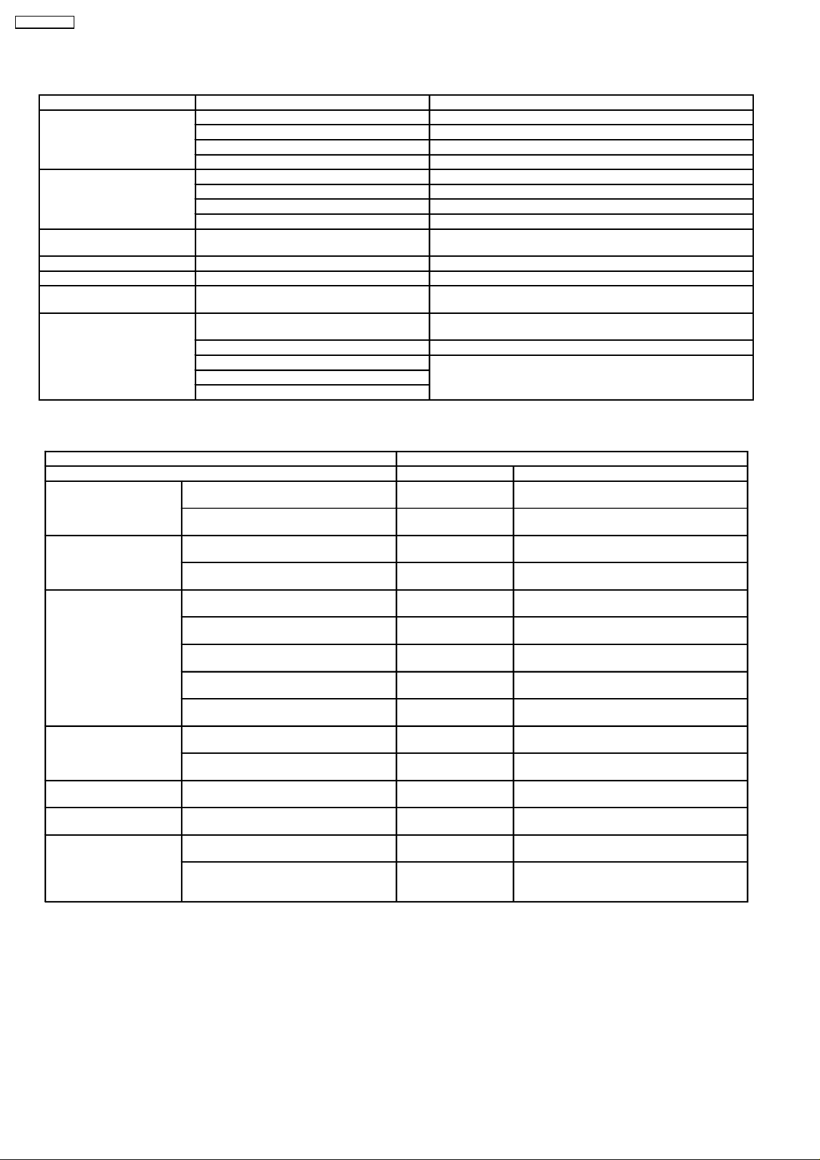
2.3.3. TROUBLESHOOTING ITEMS TABLE
FUNCTION SYMPTOM REFERENCE
Printing Skewed receiving image See SKEWED RECEIVING IMAGE (P.32)
Expanded print See EXPANDER PRINT (WHEN PRINTING) (P.33)
Image is distorted See IMAGE IS DISTORTED (WHEN PRINTING) (P.31)
Black or White vertical lines appear. See BLACK OR WHITE VERTICAL LINES APPEAR (P.32)
(Auto Document Feeder)
ADF
Abnormal mechanical sound Abnomal sound from the product See WHEN COPYING OR PRINTING, AN ABNORMAL SOUND
Power supply Voltage output is abnormal. See POWER SUPPLY BOARD SECTION (P.67)
Operation panel keys are not accepted. See OPERATION BOARD SECTION (P.71)
Sensor If the electric circuit is the cause, “REMOVE
Communication
FAX, TEL
(Analog/Digital board)
No feed See NO DOCUMENT FEED (P.27)
Paper jam See DOCUMENT JAM (P.28)
Multiple feed See MULTIPLE FEED (P.29)
Skew See SKEW (P.30)
IS HEARD FROM THE UNIT (P.33)
See SENSOR SECTION (P.72)
DOCUMENT” will be displayed.
Cannot communicate by fax. See DEFECTIVE ITS (INTEGRATED TELEPHONE SYSTEM)
SECTION (P.66)
Error code is displayed. See HOW TO OUTPUT THE JOURNAL REPORT (P.44)
Cannot talk. See ANALOG BOARD SECTION (P.65)
DTMF tone doesn’t work.
Handset/Monitor sound, volume
2.3.3.1. SIMPLE CHECK LIST
SERIAL NO. DATE
FUNCTION JUDGEMENT REFERENCE
FAX operation Transmission OK / NG
Receiving OK / NG
Copy operation FINE mode OK / NG
PHOTO mode OK / NG
Telephone operation Handset transceiver / receiver OK / NG
Monitor sound OK / NG
Ringer sound OK / NG
Dial operation OK / NG
Volume operation OK / NG
Operation Panel Key check OK / NG Service code #561
LCD check OK / NG Service code #558
Sensor Sensor check OK / NG Service code #815
Clock OK / NG Is the time kept correctly?
External Telephone Handset transceiver/receiver OK / NG
(Refer to TEST FUNCTIONS (P.82).)
(Refer to TEST FUNCTIONS (P.82).)
(Refer to TEST FUNCTIONS (P.82).)
Check with another clock.
Remote control OK / NG Change to FAX receiving by pressing * 9.
Note:
• • Check according to the sevvice code referring to the TEST FUNCTIONS (P.82).
26
(Refer to code no. 041.on PROGRAM MODE
TABLE (P.54).)
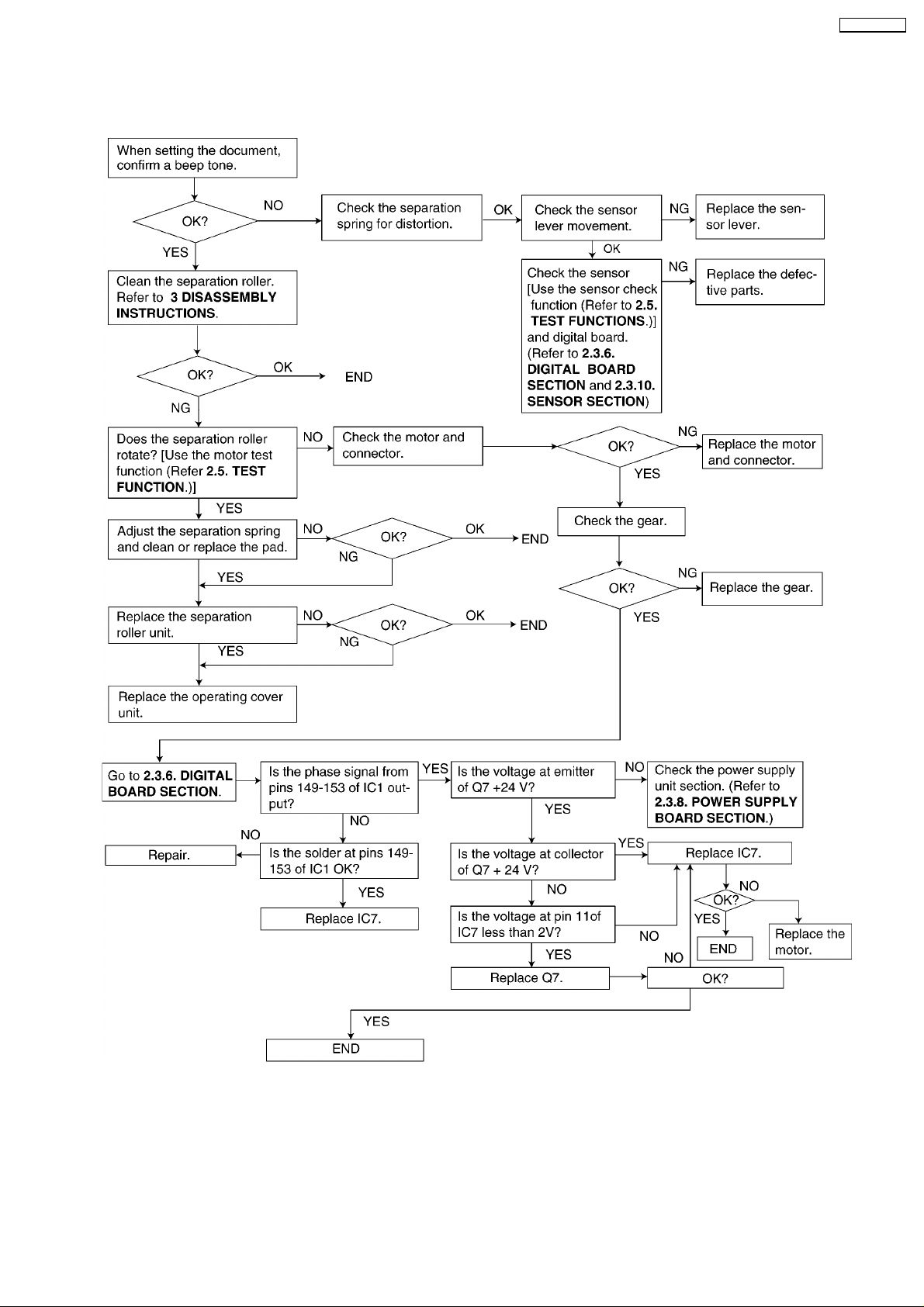
2.3.4. ADF (AUTO DOCUMENT FEED) SECTION
2.3.4.1. NO DOCUMENT FEED
KX-FT72BR-G
CROSS REFERENCE:
DIGITAL BOARD SECTION (P.56)
POWER SUPPLY BOARD SECTION (P.67)
SENSOR SECTION (P.72)
TEST FUNCTIONS (P.82)
DISASSEMBLY INSTRUCTIONS (P.84)
27
KX-FT72BR-G
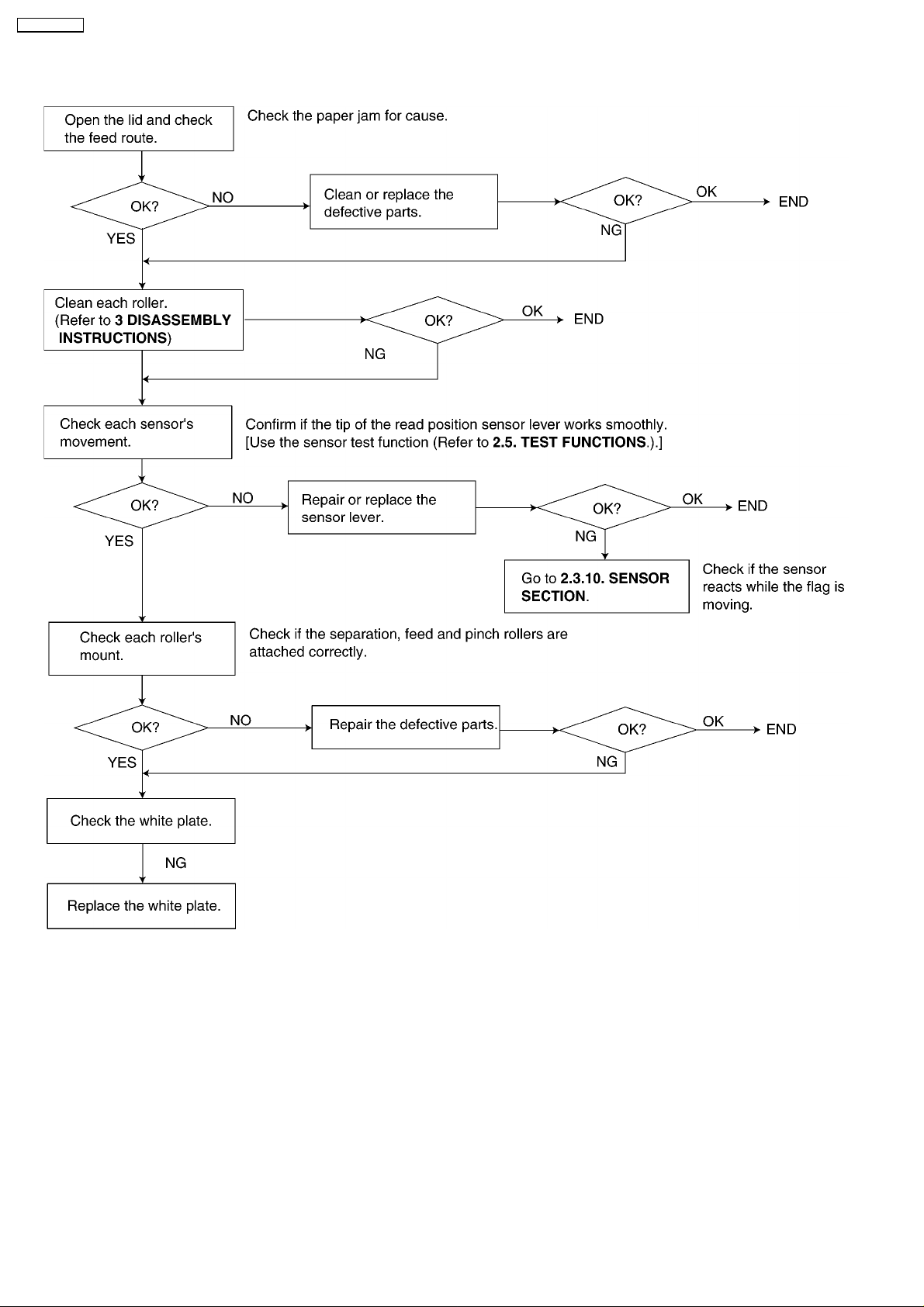
2.3.4.2. DOCUMENT JAM
CROSS REFERENCE:
SENSOR SECTION (P.72)
DISASSEMBLY INSTRUCTIONS (P.84)
28
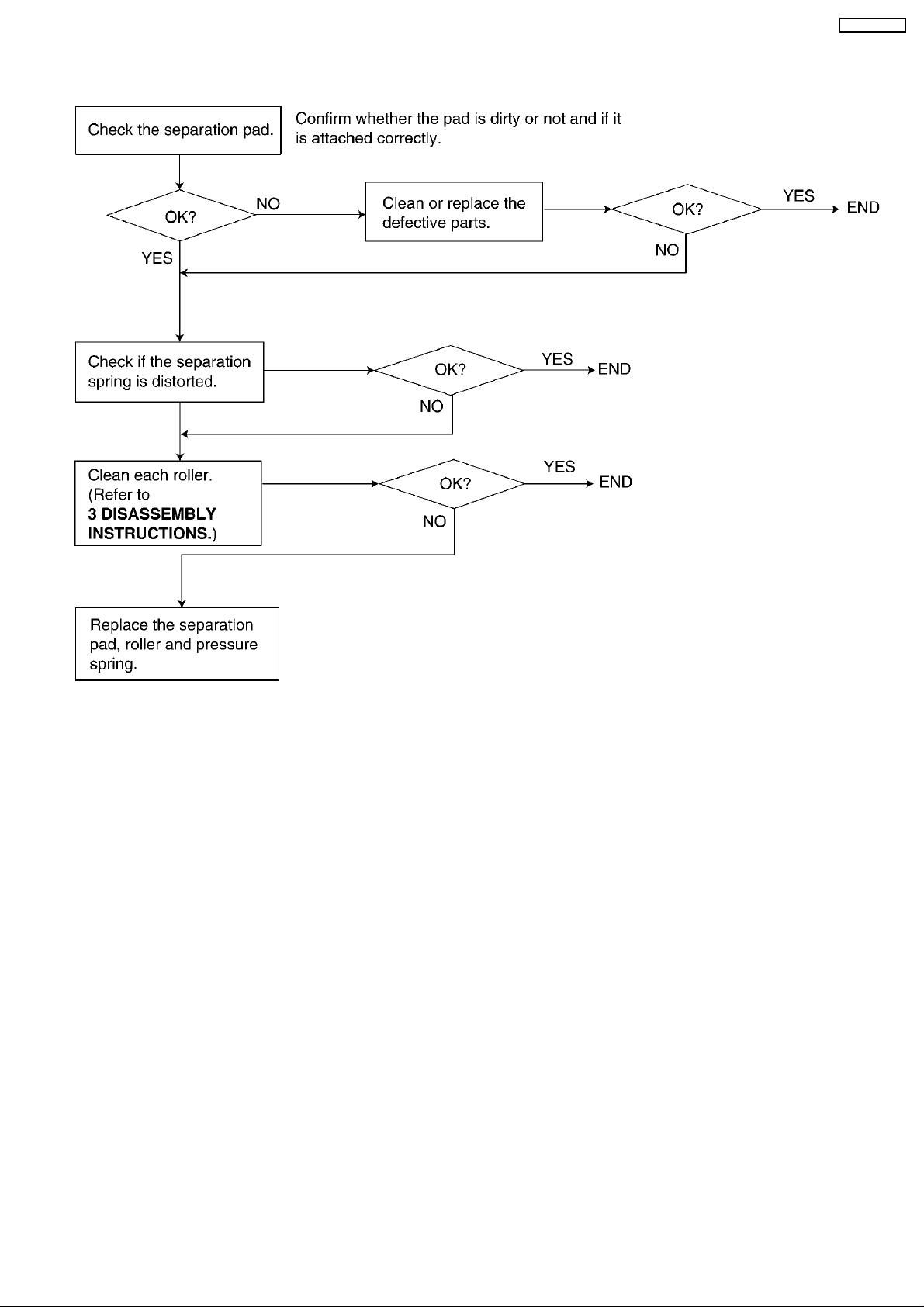
2.3.4.3. MULTIPLE FEED
KX-FT72BR-G
CROSS REFERENCE:
DISASSEMBLY INSTRUCTIONS (P.84)
29
KX-FT72BR-G
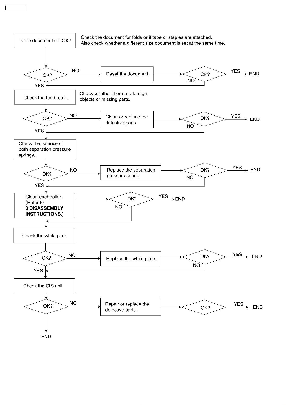
2.3.4.4. SKEW
CROSS REFERENCE:
DISASSEMBLY INSTRUCTIONS (P.84)
30
 Loading...