

Panasonic MDF-U700VX-PB, MDF-U700VX-PK, MDF-U700VX-PE, MDF-U700VXC-PA Operating Instructions Manual
Please read these instructions carefully before using this product, and save this operating instructions
for future use.
See page 54 for all Model Numbers.
MDF-U700VX
MDF-U700VXC
Series
MDF-U700VX
MDF-U700VXC
Ultra-Low Temperature Freezer
Operating Instructions

1
CONTENTS
INTRODUCTION P. 2
PRECAUTIONS FOR SAFE OPERATION P. 3
ENVIRONMENTAL CONDITIONS P. 7
FREEZER COMPONENTS P. 8
Control panel P. 10
REMOTE ALARM TERMINAL P. 11
AIR INTAKE PORT P. 11
INSTALLATION SITE P. 12
INSTALLATION P. 13
START-UP OF UNIT P. 14
Operation after power failure P. 14
FUNCTION OF CONTROL PANEL P. 15
TOP SCREEN OF CONTROL PANEL P. 16
RUNNING OPERATION (MENU/Set) P. 17
Chamber temperature setting (Temperature) P. 18
Alarm temp. setting (High Alarm/ Low Alarm) P. 19
Alarm delay time setting (Alarm Delay) P. 20
Ring back of alarm buzzer setting (Ring Back) P. 21
Key lock function P. 22
Key lock release function P. 23
VARIOUS SETTING (MENU/Log) P. 24
Display of log (Log) P. 24
Indication of log and transmission P. 25
VARIOUS SETTING (MENU/Tools) P. 27
Initialization (Tools/ Default Setting) P. 27
Set of date, time, log interval (Tools/Date Time) P. 28
Set of door alarm delay time (Tools/Door Delay) P. 29
Set of log interval (Tools/Log Interval) P. 30
Change of compressor delay time (Tools/Comp. Delay) P. 31
Set of key lock password (Tools/Key Lock PW Setting) P. 32
ALALRM BUZZER P. 32
MONITOR OF FREEZER STATUS P. 33
ALARMS & SAFETY FUNCTIONS P. 34
ROUTINE MAINTENANCE P. 36
Cleaning of cabinet P. 36
Defrosting of inside wall P. 36
Cleaning of air intake port P. 37
TROUBLESHOOTING P. 38
DISPOSAL OF UNIT P. 39
Recycle of battery P. 39
Decontamination of unit P. 39
DISPOSAL OF BATTERY P. 44
TEMPERATURE RECORDER (OPTION) P. 45
Setting of MTR-85H P. 45
Setting of MTR-G85C P. 47
BACKUP COOLING KIT (OPTION) P. 49
SMALL INNER DOOR (OPTION) P. 51
INTERFACE BOARD (OPTION) P. 51
Installation of MTR-480/MTR-L03 P. 51
INVENTRY RACK (OPTION) P. 52
SPECIFICATIONS P. 53
PERFORMANCE P. 54
SAFETY CHECK SHEET P. 55

2
INTRODUCTION
Read this operating instructions carefully before using the appliance and follow the instructions for
safety operation.
Our company never guarantee any safety if the appliance is used for any objects other than intended
use or used by any procedures other than those mentioned in this operating instructions.
Keep this operating instructions in an adequate place to refer to it as necessary.
The contents of the operating instructions will be subjected to change without notice due to the
improvement of performance or functions.
Contact our sales representative or agent if any page of the operating instructions is lost or page order
is incorrect.
Contact our sales representative or agent if any point in this operating instructions is unclear or if there
are any inaccuracies.
No part of this operating instructions may be reproduced in any form without the expressed written
permission of our company.
CAUTION
Our company guarantees the product under certain warranty conditions. Our company in no
way shall be responsible for any loss of content or damage of content.
Microsoft, Windows, Windows 7, Windows Vista, Windows XP and Windows 2000 are registered
trademarks in the United States of Microsoft Corporation and various other countries.
3
PRECAUTIONS FOR SAFE OPERATION
It is imperative that the user complies with this operating instructions
as it contains important safety advice.
Items and procedures are described so that you can use this unit correctly and safely.
If the precautions advised are followed, this will prevent possible injury to the user and
any other person.
Precautions are illustrated in the following way:
WARNING
Failure to observe WARNING signs could result in a hazard to personnel
possibly resulting in serious injury or death.
CAUTION
Failure to observe CAUTION signs could result in injury to personnel and
damage to the unit and associated property.
Symbol shows;
this symbol means caution.
this symbol means an action is prohibited.
this symbol means an instruction must be followed.
Be sure to keep this operating instructions in a place accessible to users of this unit.
Some warning and/or caution labels are attached on the unit. Following shows the description of such
labels.
This label is on the cover in which the electrical components of high voltage are
enclosed to prevent the electric shock. The cover should be removed by a qualified
engineer or a service personnel only.
This symbol means attention or refer to document.
This symbol means earth.
This symbol means power switch “ON”.
This symbol means power switch “OFF”.
WARNING
As with any equipment that uses CO2 gas, there is a likelihood of oxygen depletion in the vicinity
of the equipment. It is important that you assess the work site to ensure there is suitable and
sufficient ventilation. If restricted ventilation is suspected, then other methods of ensuring a
safe environment must be considered. These may include atmosphere monitoring and
warning devices.
4
PRECAUTIONS FOR SAFE OPERATION
Do not use the unit outdoors.
Current leakage or electric shock may result if the unit is exposed to
rain water.
Only qualified engineers or service personnel should install the unit.
The installation by
unqualified personnel may cause electric shock or fire.
Install the unit on a sturdy floor and take an adequate precaution to prevent the unit from
turning over.
If the floor is not strong enough or the installation site is not adequate, this may result
in injury from the unit falling or tipping over.
Never install the unit in a humid place or a place where it is likely to be splashed by water.
Deterioration of the insulation may result which could cause current leakage or electric shock.
Never install the unit in a flammable or volatile location.
This may cause explosion or fire.
Never install the unit where acid or corrosive gases are present
as current leakage or electric
shock may result due to corrosion.
Always ground (earth) the unit to prevent electric shock.
If the power supply outlet is not
grounded, it will be necessary to install a ground by qualified engineers.
Never ground the unit through a gas pipe, water main, telephone line or lightning rod.
Such
grounding may cause electric shock in the case of an incomplete circuit.
Connect the unit to a power source as indicated on the rating label attached to the unit.
Use
of any other voltage or frequency other than that on the rating label may cause fire or electric shock.
Never store volatile or flammable substances
in this unit if the cylinder cannot be sealed. These
may cause explosion or fire.
Do not insert metal objects such as a pin or a wire into any vent, gap or any outlet on the unit.
This may cause electric shock or injury by accidental contact with moving parts.
Use this unit in safe area when treating the poison, harmful or radiate articles.
Improper use
may cause bad effect on your health or environment.
Turn off the power switch (if provided) and disconnect the power supply to the unit prior to any
repair or maintenance
of the unit in order to prevent electric shock or injury.
Do not touch any electrical parts (such as power supply plug) or operate switches with a wet
hand.
This may cause electric shock.
WARNING
5
PRECAUTIONS FOR SAFE OPERATION
Ensure you do not inhale or consume medication or aerosols
from around the unit at the time of
maintenance. These may be harmful to your health.
Never splash water directly onto the unit
as this may cause electric shock or short circuit.
Never put cylinders with liquid on the unit
as this may cause electric shock or short circuit when
the liquid is spilled.
Never bind, process, or step on the power supply cord, or never damage or break the power
supply plug.
A broken supply cord or plug may cause fire or electric shock.
Do not use the supply cord if its plug is loose.
Such supply cord may cause fire or electric shock.
Never disassemble, repair, or modify the unit yourself.
Any such work carried out by an
unauthorized person may result in fire, or electric shock or injury due to a malfunction.
Disconnect the power supply plug if there is something wrong with the unit.
Continued
abnormal operation may cause electric shock or fire.
When removing the plug from the power supply outlet, grip the power supply plug,
not the cord.
Pulling the cord may result in electric shock or fire by short circuit.
Disconnect the power supply plug
before moving the unit. Take care not to damage the power
cord. A damaged cord may cause electric shock or fire.
Disconnect the power plug when the unit is not used for long periods.
Keeping the connection
may cause electric shock, current leakage, or fire due to the deterioration of insulation.
If the unit is to be stored unused in an unsupervised area for an extended period,
ensure that
children do not have access and that doors cannot be closed completely with a key.
The disposal of the unit should be accomplished by appropriate personnel.
Remove doors to
prevent accidents such as suffocation.
Do not put the packing plastic bag within reach of children
as suffocation may result.
WARNING
6
PRECAUTIONS FOR SAFE OPERATION
This unit must be plug into a dedicated circuit protected by branch circuit breaker.
Use a dedicated power source
as indicated on the rating label attached to the unit. A multiple-tap
may cause fire resulting from abnormal heating.
Connect the power supply plug to the power source firmly after removing the dust on the plug.
A dusty plug or improper insertion may cause a heat or ignition.
Never store corrosive substances such as acid or alkali
in this unit if the cylinder cannot be sealed.
These may cause corrosion of inner components or electric parts.
Check the setting when starting up of operation after power failure or turning off of power
switch.
The stored items may be damaged due to the change of setting.
Be careful not to tip over the unit
during movement to prevent damage or injury.
Prepare a safety check sheet (copy the last page)
when you request any repair or maintenance for
the safety of service personnel.
CAUTION

7
ENVIRONMENTAL CONDITIONS
This equipment is designed to be safe at least under the following conditions (based on the IEC 61010-1):
Indoor use;
Altitude up to 2000 m;
Ambient temperature 5oC to 40oC;
Maximum relative humidity 80% for temperature up to 31oC decreasing linearly to 50% relative humidity
at 40
o
C;
Mains supply voltage fluctuations up to ±10% of the nominal voltage;
Transient overvoltages up to the levels of OVERVOLTAGE CATEGORY II;
Temporary OVERVOLTAGES occurring on the mains supply;
Applicable pollution degree of the intended environment (POLUTION DEGREE 2 in most cases);
8
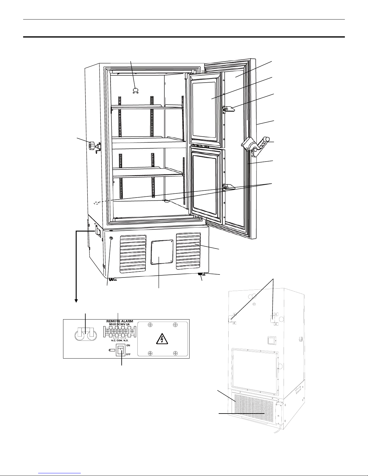
FREEZER COMPONENTS
Rear side
A compressor
B compressor
16
17
15
4
1
3
5
6
8
11
7
9
10
12
13
2
14
POWER
7

9
FREEZER COMPONENTS
1. Outer door:
To open the door, grip the handle. On closing, lock the door latch completely.
2. Inner door:
The operation of the inner door should be quick to minimize the temperature rise in
chamber. Lock the inner door latch completely when the inner door is closed. The inner door is
removable for cleaning or defrosting. See page 36 “Routine maintenance”.
3. Inner door latch:
Always lock the inner door latch when the inner door is closed.
4. Control panel (on the upper front of the outer door):
Used for temperature setting and indication
of operating status is displayed on the panel. See page 10 for details.
5. Door latch:
Always lock the latch when the outer door is closed.
6. Magnetic door gasket:
This provides a tight door seal and prevents cold air leak. Keep clean.
7. Access port (rear and bottom):
This is used for leading a cable and sensor of a measuring
equipment, or nozzle of backup cooling kit to chamber.
8. Air intake vent (grille):
Do not block this vent to keep the proper cooling performance.
9. Leveling foot:
The height of the freezer can be adjusted by this screw type foot. Keep the unit in
level at the installation.
10. Caster:
4 casters are provided to facilitate moving of the cabinet. For the installation, adjust the
leveling feet so that the front 2 casters cannot contact with the floor.
11. Space for temperature recorder:
A temperature recorder (optional component) can be attached
here. See page 45 “Temperature recorder (Option)”.
12. Lock:
Turn clockwise to 180o with a key and the outer door is securely locked.
13. Air intake port:
When a door is closed and opened soon, this air intake port is used. See page 11
14. Fixture (on back side):
2 fixtures are provided as spacers between the cabinet and wall and also
serve as hooks to fix the unit. See page 13 “Installation”.
15. Power switch:
This is for turning ON/OFF the power to the unit.
16. Remote alarm terminal:
This is used to notice an alarm condition of the unit to remote location.
Refer to page 11 “Remote alarm terminal”.
17. Battery switch:
This is a switch for a battery for power failure alarm. Normally, turn on this switch.
Be sure to turn off this switch if the freezer is not in operating for the long period (over one month).
WARNING
Fix the shelf stoppers and shelves securely. Incomplete installation may cause injury or damage.
Never touch the storage items with wet hands. Touching with the wet hands may cause frostbite
10
FREEZER COMPONENTS
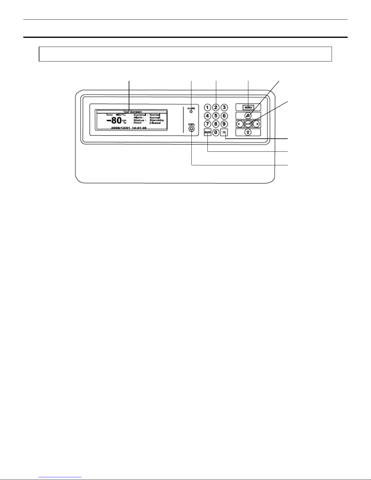
Control panel
1. LCD panel
2. Alarm lamp (ALARM):
This lamp is flashed during alarm condition.
3. Figure input key:
User for operation setting.
4. Menu button (MENU):
To open the menu window during setting.
5. Shift key (Upward, downward, rightward, leftward):
To move the cursor on the LCD panel during
setting.
6. Enter key (ENTER):
To determine the selection of parameter during setting.
7. Clear key (CE):
To clear the input value during setting or to return to the top screen after setting.
8. Buzzer stop key (BUZZER):
This key has three functions as follows:
-
Buzzer stop key : To silence the audible alarm under alarm condition, press this key. Refer to page
34 and 35 for the details.
-
Alarm test key: By pressing this key for 5 seconds during normal operation, the alarm lamp blinks, the
buzzer sound and the remote alarm activates. Pressing this key again finishes the alarm test. Refer
to page 15 as well.
-
Chamber temperature display key: The chamber temperature is displayed by pressing this key during
power failure.
9. LCD contrast adjusting knob (CONT.):
To adjust the contrast of LCD panel.
1
2
4
5
9
8
7
3
6
11
REMOTE ALARM TERMINAL
The terminal of the remote alarm is installed at the lower left side of the unit. The alarm is outputted
from this terminal. Contact capacity is DC 30 V, 2 A.
Contact output:
between COM. and N.O. between COM. and N.C.
At normal Open Close
At abnormal Close Open
Note:
• The buzzer is silenced by pressing buzzer stop key (BUZZER) on the control panel during alarm
condition. (A remote alarm is continuing the operation.)
The buzzer will be activated again after certain suspension if the alarm condition is continued.
• The alarm is actuated when the power supply plug is disconnected from the outlet or the power switch is
OFF.
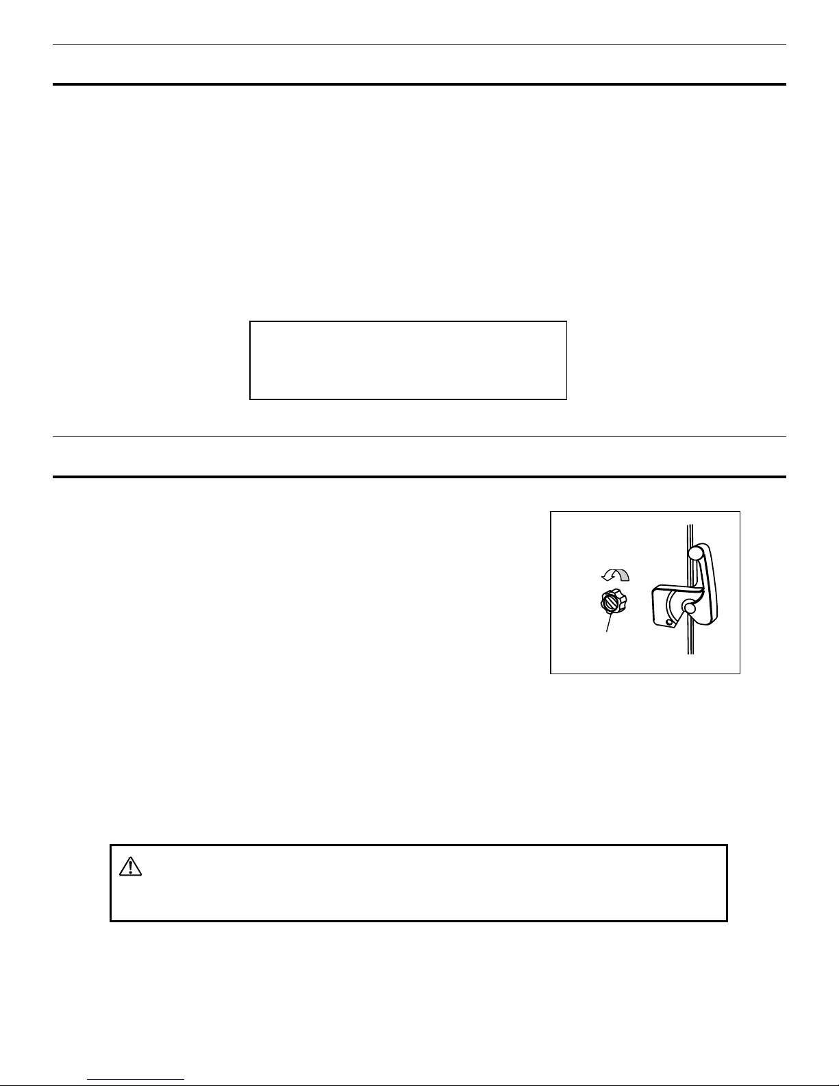
AIR INTAKE PORT
When a door is closed and opened soon, a door does not
sometimes open this product.
The warm air which went into the chamber is cooled down rapidly,
and this is because air inside the chamber contracted.
When a door is closed and opened soon, a door is easy to open
with the following process.
1.
Turn the cap of the left side counterclockwise about two laps.
(That can be removed completely)
2.
Put the air into the chamber from about twenty seconds, and
open a door.
3.
Close a cap if a door opens.
A door may not open in the above method when there are frost and ice in the air intake port. In that
case, open a cap, and investigate the matter whether there is no frost inside the air intake port. Remove
frost inside the air intake port by "
Stick for air intake port cleaning" of the accessories when there is frost.
Clean a air intake port every month even when there is no frost inside the air intake port. Refer to page
37.
WARNING
For removing the frost of the air intake port, do not use a tool with sharp edge such as a knife or a screw
driver.
Cap
Two laps
Use a twisted sealed wire for the connection.
Type UL2343, UL2448, UL2464, UL2552, UL 2623
Length: 30 m max.
12
INSTALLATION SITE
To operate this unit properly and to obtain maximum performance, install the unit in a location with the
following conditions:
A location not subjected to direct sunlight
Do not install the unit under direct sunlight. Installation in a location subjected to direct sunlight cannot
obtain the intended performance.
A location with adequate ventilation
Leave at least 10 cm around the unit for ventilation. Poor ventilation will result in a reduction of the
performance and consequently the failure.
A location away from heat generating sources
Avoid installing the unit near heat-emitting appliances such as a heater or a boiler etc. Heat can
decrease the intended performance of the unit.
A location with little temperature change
Install the unit under stable ambient temperature. The allowable ambient temperature is between +5
and +30
o
C.
A location with a sturdy and level floor
Always install the unit on a sturdy and level floor. The uneven floor or tilted installation may cause failure
or injury. Install the unit in stable condition to avoid the vibration or noise. Unstable condition may
cause vibration or noise.
WARNING
Install the unit on a sturdy floor.
If the floor is not strong enough or the installation site is not
adequate, this may result in injury from the unit falling or tipping over.
Select a level and sturdy floor for installation.
This precaution will prevent the unit from tipping.
Improper installation may result in water spillage or injury from the unit tipping over.
A location not prone to high humidity
Install the unit in the ambient of 80% R.H. or less humidity. Installation under high humidity may cause
current leakage or electric shock.
WARNING
Do not use the unit outdoors.
Current leakage or electric shock may result if the unit is exposed to
rain water.
Never install the unit in a humid place or a place where it is likely to be splashed by water.
Deterioration of the insulation may result which could cause current leakage or electric shock.
A location without flammable or volatile gas
Never install the unit in a flammable or volatile location. This may cause explosion or fire or may result
in the current leakage or electric shock by the corrosion of the electrical components.
A location without the possibility of anything fall
Avoid installing the unit in the location where anything can fall down onto the unit. This may cause the
breakdown or failure of the unit.
13
INSTALLATION
1. Remove the packaging materials and tapes
Remove all transportation packaging materials and tapes. Open the doors and ventilate the unit. If the
outside panels are dirty, clean them with a diluted neutral dishwashing detergent. (Undiluted detergent
can damage the plastic components. For the dilution, refer to the instruction of the detergent.) After
the cleaning with the diluted detergent, always wipe it off with a wet cloth. Then wipe off the panels with
a dry cloth.
Note:
Remove the cable tie banding the power supply cord.
Prolonged banding may cause the corrosion of the
cord coating.
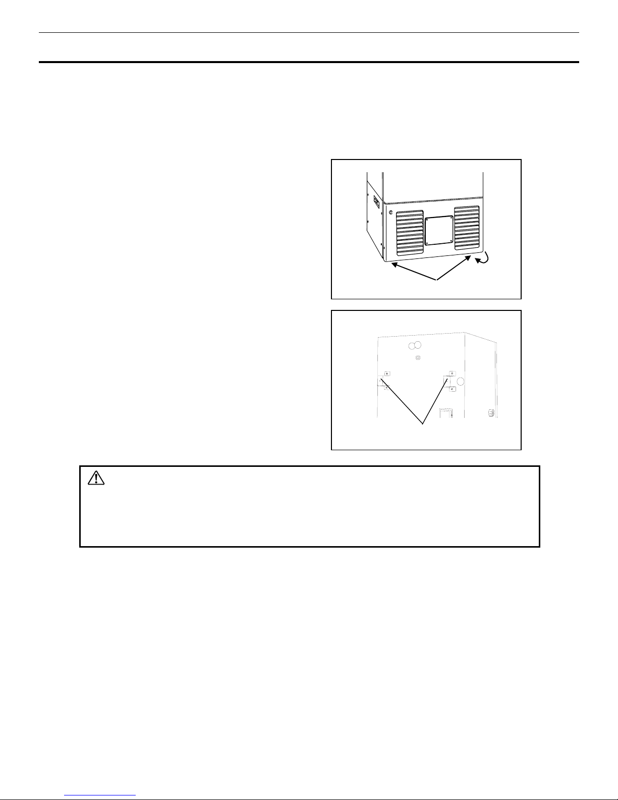
2.
Adjust the leveling foot
Extend the leveling feet by rotating them
counterclockwise to contact them to the floor.
Ensure the unit is level. (Fig.1)
3.
Fix the unit
Two fixtures are attached to the rear of the frame.
Fix the frame to the wall with these fixtures and rope
or chain. (Fig. 2)
WARNING
Use a power supply outlet with ground (earth)
to prevent electric shock. If the power supply outlet is
not grounded, it is necessary to install a ground by qualified engineers.
Never ground the unit through a gas pipe, water main, telephone line or lightning rod.
Such
grounding may cause electric shock in the case of an incomplete circuit.
4. Installation branch circuit breaker
This product is to be connected to a dedicated circuit protected by branch circuit breaker.
Contact our sales representative or agent.
Fixture
Fig.1
Fig. 2
Leveling foot
14
START-UP OF UNIT
Follow the procedures for the initial and consequent operations of the unit.
1.
Connect the power cord to the dedicated outlet having appropriate rating with the chamber empty, and
turn on the power switch on the freezer.
2.
Turn off the switch of the backup cooling kit (optional component) if it is installed.
3.
Turn on the battery switch.
4.
The audible alarm may activated. In this case, press the buzzer stop key (BUZZER) to silence the
alarm.
5.
Set the desired chamber temperature. See page 18 for the temperature setting.
6.
Check that the chamber temperature reaches the desired temperature.
7.
Turn on the switch of backup cooling kit (optional component) if it is installed.
8.
Check that the alarm lamp blinks and the buzzer sounds by pressing the alarm test key.
9.
After confirming the above, you can put articles into the chamber in a small batch to prevent the
temperature rise.
CAUTION
Do not put too many warm articles in the chamber. The temperature rise may cause the damage to
the articles in the chamber.
Operation after power failure
The set value is memorized by nonvolatile memory. Accordingly, the chamber resumes the operation
with setting before power failure. During the power failure, the clock function is operating.
WARNING
When this product operates at the first start-up or after no use for long period, the built-in battery capacity
may be lowered or completely zero because of discharge of the battery. After installation the product,
the freezer should operate for more than 3 days (72 hours) to charge the battery.

15
FUNCTION OF CONTROL PANEL
The following functions are available through control panel:.
1. Setting of standby operation:
To set a running condition at the start-up.(refer to page 17)
2. Setting of log interval and sending to PC:
To set a log interval (page 30) and to send a log date to
PC.
(
refer to page 25) When this function is used, an optional interface board is necessary. Contact
our sales representative or agent at the time of installation of the optional parts.(refer to page 51)
3. Setting of date and time:
To set the date and time shown on the top screen.(refer to page 28)
4. Setting of alarm:
To set the high or low temperature alarm(refer to page 19). Also, to set the alarm
delay (refer to page 20).
5. Default setting:
To set the default items including LCD back color.(refer to page 27)
6. Alarm test:
The test of alarm buzzer, alarm lamp and remote alarm is effective by pressing the
buzzer stop key (BUZZER) for about five seconds during normal operation. Pressing the key again
finishes the alarm test.
1. Running operation (Set):
1-1 Chamber temperature (Temperature): -80
o
C (Default setting) (Setting range: -50oC - -90oC)
(Refer to page 18)
1-2 High temperature alarm (High Alarm): +10
o
C (Default setting) (Setting range:+5oC - +40oC)
(Refer to page 19)
1-3 Low temperature alarm (Low Alarm): -10
o
C (Default setting) (Setting range:-5oC - -40oC) (Refer
to page 19)
1-4 Alarm delay time (Alarm Delay): 15 min. (Default setting) (Setting range: 0 -15 min.) (Refer to
page 20)
1-5 Ring back of buzzer (Ring Back): 30 min. (Default setting) (Setting range: 0, 1 – 99 min.) (Refer
to page 21)
1-6 Key lock (Key Lock): 0 (Default setting), 0: Unlock, 1: Lock (Refer to page 22 – 23)
2. Log (Log): When this function is used, an optional interface board is necessary. Contact our sales
representative or agent at the time of installation of the optional parts.
2-1 Log data on past the first (PC 1D) (Refer to page 24)
2-2 All of the log data (PC ALL) (Up to 5 weeks) (Refer to page 25)
2-3 Clear log data (Clear) (Refer to page 25)
3. Various setting (Tools):
3-1 Initialization (Default Setting): When this function from 3-1-2 to 3-1-4 is used, an optional
interface board is necessary. Contact our sales representative or agent at the time of
installation of the optional parts.
3-1-1 LCD Back Color: 1 (Default Setting) (1: Blue
、
2: White) (Refer to page 27)
3-1-2 DAQ Speed: 0 (Default Setting) (0: 2400
、
2: 9600(bit/sec)) (Refer to page 27)
3-1-3 DAQ ID: 0 (Default Setting) (0: OFF
、
1 – 250) (Refer to page 27)
3-1-4 DAQ Mode: 0 (Default Setting) (0: Local
、
1: Remote) (Refer to page 27)
3-1-5 Remote Alarm: 1 (Default Setting)) 0: OFF
、
1: Active) (Refer to page 27)
3-1-6 Drive mode (Control: 0 (Default Setting) (0: Normal
、
1: ECO) (Refer to page 27)
3-2 Date
・
Time (Date Time):
3-2-1 Date: (YY/MM/DD) (Refer to page 28)
3-2-2 Time: (hh:mm:ss) (Refer to page 28)
3-2-3 Door alarm delay time (Door Delay: 2min. (Default Setting) (Setting range: 0 – 15 min)
(Refer to page 29)
3-2-4 Log Interval: 15 min (Default Setting) (Setting range: 2 – 30 min.) (Refer to page 30)
3-2-5 Comp Delay: 3 min. (Default Setting) (Setting range: 3 – 15 min.) (Refer to page 31)
3-3 Key Lock PW Setting: (Refer to page 32)
After setting, press the menu button (MENU), select “OK” and press the enter key (ENTER). The
setting is memorized.
16
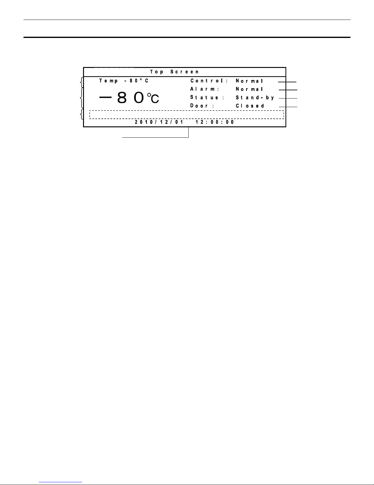
TOP SCREEN OF CONTROL PANEL
When the power switch is turned on, the top screen is displayed on the LCD panel.
1. Operation indication (Control):
"Normal" (initialization value) is indicated by the normal operation.
"ECO" is indicated in the saving energy mode. Refer to page 27.
2. Display of alarm (Alarm):
“Normal” is usually indicated. “Alarm” or “Warning” is displayed during
the alarm status and the additional message is displayed in the message column. “Test” is displayed at
the alarm test. For the details of the alarm status, refer to page 33 through page 35.
3. Display of status (Status):
“Stand-by” is usually displayed. A status number is displayed and an
additional message is displayed in the message column when the operation monitor system detects the
specified status. Refer to page 33 for the operation monitor system.
4. Display of door status (Door):
“Closed” is displayed when the door is close. “Open” is displayed
When the door is open.
5. Display of date and time:
The current date and time are displayed.
6. Message column: An
additional messages is displayed when the alarm status. Refer to page 33
through page 35 for the details.
7. Display of current value:
Current value of chamber temperature is displayed.
8. Display of setting:
Set value of chamber temperature is displayed.
1
2
8
7
5
3
6
4

17
01 0
2
11 12 13 14 15 1617181920212223242526272829303132333435363738394
0
1
T e mp . S e t t i n g
2
T e m p e r a t u r e - 8 0 oC ( - 5 0oC - -90oC)
3
H i g h A l a r m + 1 0 oC ( + 5 oC - + 20oC)
4
L o w A l a r m - 1 0 oC ( - 5 oC - -20oC)
5
A l a r m D e l a y 1 5 m i n ( 0 - 1 5 mi n )
R i n g B a c k 3 0 m i n ( 0 . O F F 1 - 9 9 m i n)
6
K e y L o c k 0 ( 0 . U n l o c k 1 . L o c k )
MENU
O K
Ca n c e l
RUNNING OPERATION (MENU/Set)
This product is operated with set temperature at the time of start-up.
1.
With the top screen displayed, press the menu button (MENU) to show the menu window. Select
“Set”, and press the enter key (ENTER).
2.
A setup screen (Temp. Setting) is displayed. Set up each parameter.
1. Temperature : This is a setting of chamber temperature. Temperature settable range is between -50
and -90
o
C. The factory setting is -80oC.
2. High Alarm: This is a setting of high temperature alarm. Temperature settable range: between
chamber temperature +5 and +40
o
C The factory setting is chamber temperature +10oC.
3. Low Alarm: This is a setting of low temperature alarm. Temperature settable range: between
chamber temperature -5 and -40
o
C The factory setting is chamber temperature -10oC.
4. Alarm Delay: This is a setting of delay time of alarm buzzer for high and low temperature alarm. The
settable range is between 0 and 15 minutes. When 0 is set, the alarm buzzer sound without delay.
The factory setting is 15 minutes.
5. Ring Back: This is the duration between the stop of alarm buzzer and next start of alarm buzzer. The
settable range is between 1 and 99 minutes. The alarm buzzer is not back again when the setting is 0.
(OFF). The factory setting is 30 minutes.
6. Key Lock: When 1 (Lock) is selected, the setting cannot be changed. The input of the password is
necessary at the time of unlock.
3.
Press the menu button (MENU) to finish the settlement of each parameter. Select OK on the menu
window, and press the enter key (ENTER). The setting is memorized and the setup screen returns to
the top screen.
Select Cancel on the menu window, and press the enter key (ENTER). The setting is not memorized
and the setup screen returns to the top screen.
Choose OK by this menu window, and push an enter key when you memorize the value of the
running operation and the setting. And, when Cancel is chosen, various setting value is not
memorized.
1
2
3
4
5
6
 Loading...