

Panasonic LNA4501F Datasheet
Visible Light Emitting Diodes (Red)
LNA4501F
GaAlAs Red Light Emitting Diode
For optical fiber communications and control systems
Features
Red light emission close to monochromatic light : λP = 680 nm
High-power output, high-efficiency : PO = 3 mW
High coupling characteristics and suits to a plastic fiber
High-speed response : –3dB modulation of 10 MHz
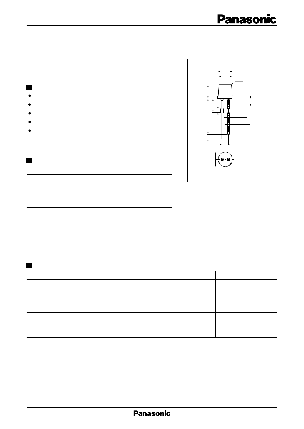
Flat resin package : ø 4.8 mm
Unit : mm
ø4.8±0.2
ø4.4±0.2
C0.2
5.0±0.2
4.4±0.3
1.0
12.5±1.0
Not soldered 2.0 max.
2-1.0±0.1
2- 0.6±0.15
(1.5)
Absolute Maximum Ratings (Ta = 25˚C)
2.54
2
1
ø5.4±0.2
Parameter Symbol Ratings Unit
Power dissipation P
Forward current (DC) I
Pulse forward current I
Reverse voltage (DC) V
Operating ambient temperature
Storage temperature T
*
tw = 10 µs, Duty cycle = 10 %
D
F
*
FP
R
T
opr
stg
120 mW
40 mA
200 mA
3V
–25 to +85 ˚C
–30 to +100 ˚C
Electro-Optical Characteristics (Ta = 25˚C)
Parameter Symbol Conditions min typ max Unit
Radiant power P
Peak emission wavelength λ
Spectral half band width ∆λ IF = 20mA 20 nm
Forward voltage (DC) V
Reverse current (DC) I
Response time tr, t
Half-power angle θ
Note : Before using this product, be sure provide and/or receive approvals regarding individual specifications.
IF = 20mA 1 3 mW
O
IF = 20mA 680 nm
P
IF = 20mA 1.8 2.6 V
F
VR = 3V 100 µA
R
I
f
= 100mA 30 ns
FP
The angle in which radiant intencity is 50%
30 deg.
1: Cathode
2: Anode
1
LNA4501F Visible Light Emitting Diodes (Red)
I
— Ta
60
50
(mA)
F
40
30
20
10
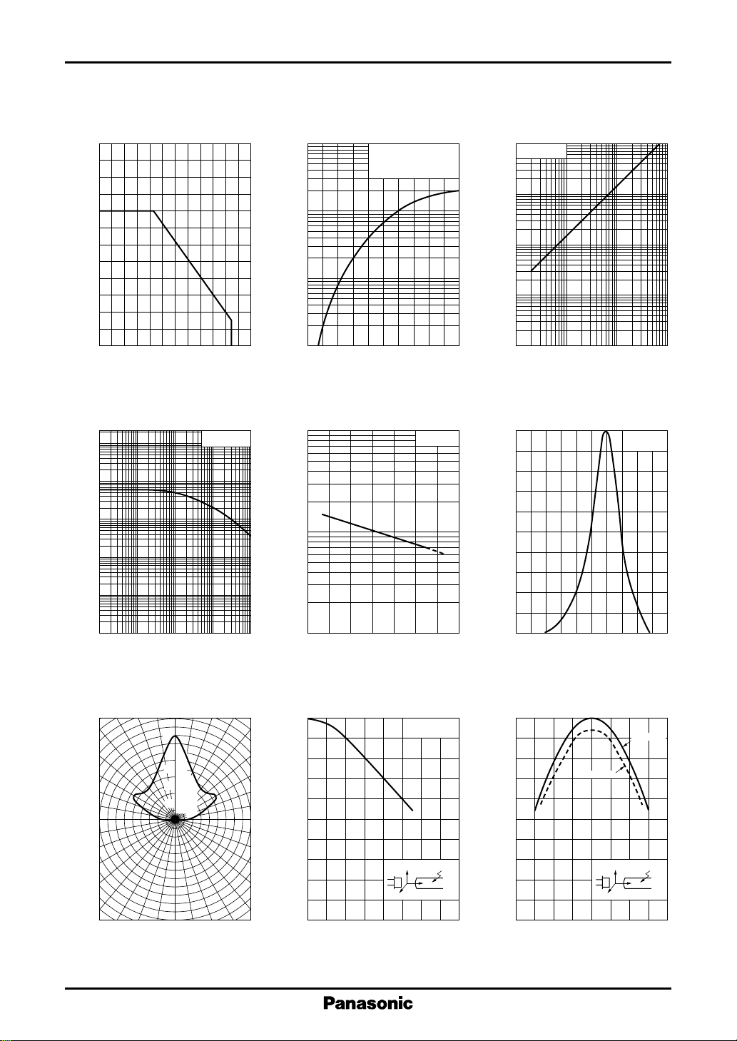
Allowable forward current I
0
– 20
F
0 20406080100
Ambient temperature Ta (˚C )
I
— Duty cycle
FP
4
10
3
10
(mA)
FP
2
10
10
Ta = 25˚C
I
10
(mA)
FP
10
10
3
2
FP
Pulse forward current I
1
Forward voltage VF (V)
∆P
3
10
O
2
10
O
— V
F
t
= 10µs
w
Duty Cycle = 10%
Ta = 25˚C
— Ta
2.41.6 2.01.8 2.2
IF = 20mA
P
5
10
Ta = 25˚C
4
10
(µW)
O
3
10
2
Radiant power P
10
10
1
O
10 10
Forward current IF (mA)
Spectral characteristics
100
80
60
40
— I
F
2
10
I
= 20mA
F
3
1
Pulse forward current I
–1
10
10
–1
–2
10
1
Duty cycle (%)
Directivity characteristics
0˚ 10˚ 20˚ 30˚
100
80
60
40
20
Relative radiant
10 10
intensity (%)
2
40˚
50˚
60˚
70˚
80˚
90˚
Relative radiant power ∆P
10
– 40 0 40 80
Ambient temperature Ta (˚C )
Coupling loss characteristics
0
1
(dB)
Z
2
3
Coupling loss L
4
5
0
0.4 1.2 1.60.8
Distance Z (mm)
X,Y = 0mm
Y
X
Relative radiant intensity (%)
20
0
640 660 680 700 720
620
Wavelength λ (nm)
Coupling loss characteristics
0
Z = 0mm
1
(dB)
Y
2
, L
X
3
Fiber
Z
Coupling loss L
4
5
– 0.8
Z = 0.3mm
Y
X
– 0.4 0.4 0.80
Distance X, Y (mm)
Fiber
Z
2
 Loading...