

Panasonic LNA2901L Datasheet
Infrared Light Emitting Diodes
LNA2901L
GaAs Infrared Light Emitting Diode
For optical control systems
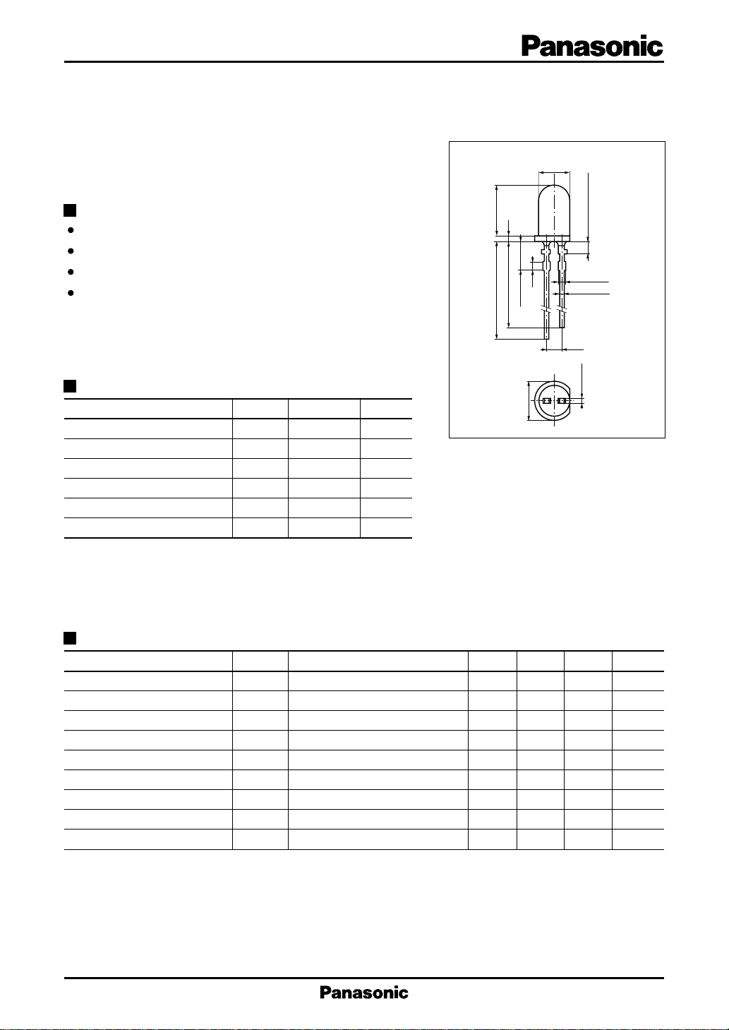
Unit : mm
ø5.0±0.2
Features
High-power output, high-efficiency : Ie = 9 mW/sr (min.)
Emitted light spectrum suited for silicon photodetectors
Transparent epoxy resin package
Long lead-wire type
Absolute Maximum Ratings (Ta = 25˚C)
Parameter Symbol Ratings Unit
Power dissipation P
Forward current (DC) I
Pulse forward current I
Reverse voltage (DC) V
Operating ambient temperature
Storage temperature T
*
f = 100 Hz, Duty cycle = 0.1 %
D
F
*
FP
R
T
opr
stg
160 mW
50 mA
1A
3V
–25 to +85 ˚C
– 40 to +100 ˚C
7.65±0.2
1.0
1.5
24.3±1.0
26.3±1.0
5.25±0.3
ø6.0±0.2
2
2-0.8 max.
2-0.6±0.15
2.54
0.6±0.15
1
Not soldered 2.25
1: Cathode
2: Anode
Electro-Optical Characteristics (Ta = 25˚C)
Parameter Symbol Conditions min typ max Unit
Center radiant intensity I
Radiant power P
Peak emission wavelength λ
Spectral half band width ∆λ IF = 50mA 50 nm
Forward voltage (DC) V
Pulse forward voltage V
Reverse current (DC) I
Capacitance between terminals
C
Half-power angle θ
*
f = 100 Hz, Duty cycle = 0.1 %
IF = 50mA 9 mW/sr
e
IF = 50mA 12 mW
O
IF = 50mA 950 nm
P
IF = 50mA 1.3 1.5 V
F
*
I
FP
R
t
= 1A 3 V
FP
VR = 3V 10 µA
VR = 0V, f = 1MHz 35 pF
The angle in which radiant intencity is 50%
20 deg.
1
LNA2901L Infrared Light Emitting Diodes
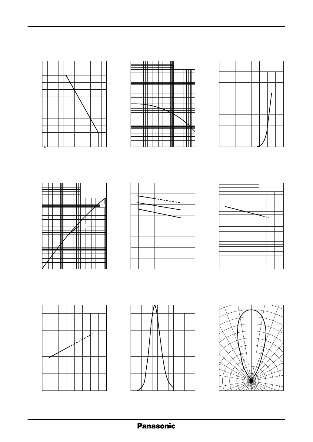
I
— Ta
60
50
(mA)
F
40
30
20
10
Allowable forward current I
0
– 25
F
0 20406080100
Ambient temperature Ta (˚C )
∆I
— I
2
10
e
10
1
e
FP
(1) tw = 10µs
f = 100Hz
(2) DC
Ta = 25˚C
(2)
I
— Duty cycle
FP
2
10
10
(A)
FP
1
–1
10
Pulse forward current I
–2
10
–1
10
11010
tw = 10µs
Ta = 25˚C
(mA)
F
Forward current I
2
80
70
60
50
40
30
20
10
0
0 0.4 0.8 1.2 1.6
Duty cycle (%)
V
— Ta
1.6
F
IF = 50mA
10mA
1mA
(1)
(V)
F
1.2
0.8
3
10
e
2
10
I
— V
F
F
Ta = 25˚C
Forward voltage VF (V)
∆I
— Ta
e
IF = 50mA
–1
10
Relative radiant intensity ∆I
–2
10
–3
10
–2
–1
10
Pulse forward current IFP (mA)
λ
— Ta
1000
980
(nm)
P
960
940
920
P
IF = 50mA
Peak emission wavelength λ
900
– 40 0 40 80 120
Ambient temperature Ta (˚C )
Forward voltage V
0.4
0
110
– 40 0 40 80 120
Ambient temperature Ta (˚C )
Spectral characteristics
100
80
60
40
Relative radiant intensity (%)
20
0
860
I
= 50mA
F
Ta = 25˚C
900 940 980 1020 1060 1100
Wavelength λ (nm)
10
Relative radiant intensity ∆I
1
– 40 0 40 80 120
Ambient temperature Ta (˚C )
Directivity characteristics
0˚ 10˚ 20˚
100
90
80
70
60
50
40
30
Relative radiant intensity (%)
20
30˚
40˚
50˚
60˚
70˚
80˚
90˚
2
 Loading...