

Panasonic LNA2702L Datasheet
Infrared Light Emitting Diodes
LN59, LNA2702L
GaAs Bi-directional Infrared Light Emitting Diodes
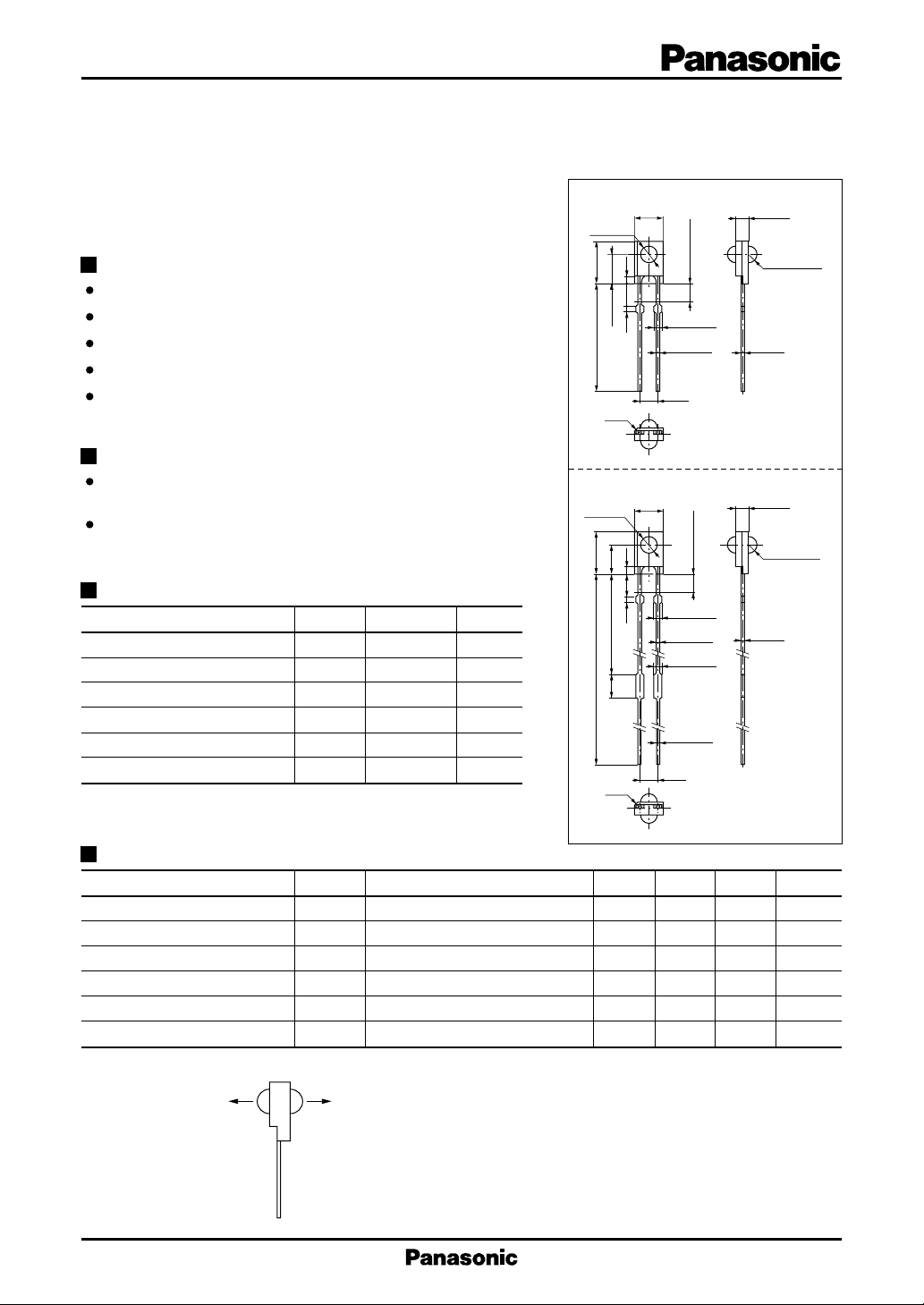
LN59
For light source of VCR (VHS System)
ø2.5±0.2
4.0±0.2
Unit : mm
1.8±0.2
Features
Two-way directivity
High-power output, high-efficiency : PO = 1.8 mW (min.)
Small resin package
Long lifetime, high reliability
Long lead wire type (LNA2702L)
1.03.31.0
6.0±0.215.3±1.0
4.0±0.2
1
C0.5
Not soldered
2-0.8 max.
2-0.5±0.1
2
2.54
2-R1.25±0.1
0.5±0.1
Applications
Light source for tape end sensor of VCR and video camera
recorder of VHS system
Light source for 2-bit photo sensor
LNA2702L
4.0±0.2
ø2.5±0.2
1.03.31.0
6.0±0.2
4.0±0.216.6
Not soldered
1.8±0.2
2-R1.25±0.1
Absolute Maximum Ratings (Ta = 25˚C)
Parameter Symbol Ratings Unit
Power dissipation P
Forward current (DC) I
Pulse forward current I
Reverse voltage (DC) V
Operating ambient temperature
Storage temperature T
*
f = 100 Hz, Duty cycle = 0.1 %
D
F
*
FP
R
T
–25 to +85 ˚C
opr
– 40 to +100 ˚C
stg
75 mW
50 mA
1A
3V
3.5
33.7±0.5
C0.5
2-0.8 max.
2-0.5±0.1
2-0.7 max.
2-0.5±0.1
2
1
2.54
0.5±0.1
Electro-Optical Characteristics (Ta = 25˚C)
Parameter Symbol Conditions min typ max Unit
Radiant power P
Peak emission wavelength λ
Spectral half band width ∆λ IF = 20mA 50 nm
Forward voltage (DC) V
Reverse current (DC) I
Capacitance between pins
*
Radiant power PO shows each value of radiant flux P1 and P2 in two directions.
*
IF = 50mA 1.8 mW
O
IF = 20mA 950 nm
P
IF = 50mA 1.3 1.5 V
F
VR = 3V 10 µA
R
C
VR = 0V, f = 1MHz 35 pF
t
1: Anode
2: Cathode
1: Anode
2: Cathode
P1 P2
1
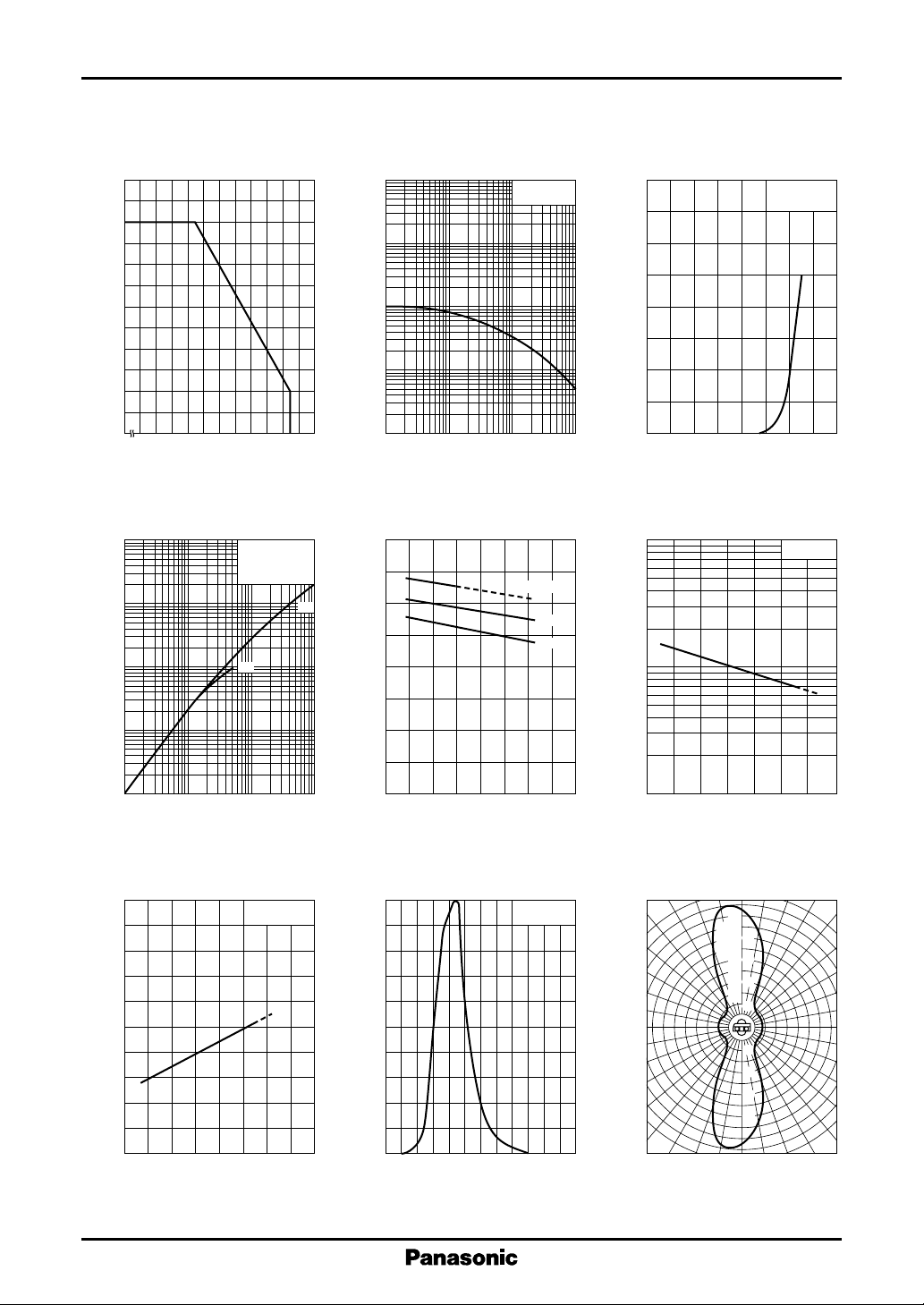
Infrared Light Emitting Diodes LN59, LN2702L
I
— Ta
60
50
(mA)
F
40
30
20
10
Allowable forward current I
0
– 25
F
0 20406080100
Ambient temperature Ta (˚C )
∆P
— I
2
10
O
10
1
O
FP
(1) tw = 10µs
f = 100Hz
(2) DC
Ta = 25˚C
(2)
I
— Duty Cycle
FP
2
10
10
(A)
FP
1
–1
10
Pulse forward current I
–2
10
–1
10
11010
tw = 10µs
Ta = 25˚C
(mA)
F
Forward current I
2
80
70
60
50
40
30
20
10
0
0 0.4 0.8 1.2 1.6
Duty cycle (%)
V
— Ta
1.6
F
IF = 50mA
10mA
1mA
(1)
(V)
F
1.2
0.8
3
10
O
2
10
I
— V
F
F
Ta = 25˚C
Forward voltage VF (V)
∆P
— Ta
O
IF = 20mA
–1
10
Relative radiant power ∆P
–2
10
–3
10
–2
–1
10
Pulse forward current IFP (A)
λ
— Ta
1000
980
(nm)
P
960
940
920
P
IF = 20mA
Peak emission wavelength λ
900
– 40 0 40 80 120
Ambient temperature Ta (˚C )
Forward voltage V
0.4
110
0
– 40 0 40 80 120
Ambienttemperature Ta (˚C )
Spectral characteristics
100
80
60
40
Relative radiant intensity (%)
20
0
860
I
= 20mA
F
Ta = 25˚C
900 940 980 1020 1060 1100
Wavelength λ (nm)
Relative radiant power ∆P
10
– 40 0 40 80
Ambient temperature Ta (˚C )
Directivity characteristics
50˚
40˚
30˚
20˚
10˚
0˚
90˚ 100˚ 110˚ 120˚60˚ 70˚ 80˚
80
lative
Re
60
40
radiant intensity (%)
20
20
40
60
80
130˚
140˚
150˚
160˚
170˚
180˚
2
 Loading...