

Panasonic KXTG7574C Operating Instructions

TGA405(bundle)(e).fm Page 1 Thursday, February 4, 2010 10:12 AM
Range Extender
Model No.
KX-TGA405
KX-TGA405C
Installation Guide for Range Extender
By installing this unit, you can extend the range of your phone system to include
areas where reception was previously not available.
The unit extends the range in all directions, allowing several floors to be covered.
Important:
LThis unit is an accessory unit for use with Panasonic Digital Cordless phones.
LThis unit is pre-registered to the base unit.
LThis leaflet only describes the steps needed to install and use the unit. Refer to the
base unit’s operating instructions for accessory information, important information
for safety, FCC and other information (for U.S.A. users only), and Industry Canada
Notices and other information (for Canada users only).
For best performance
Placement
LInstall the unit within base unit range in an indoor environment. We recommend
installing the unit in a raised position (such as on a wall).
LAvoid positioning the unit close to objects that will interfere with reception, such as
thick walls, radiators, metal shelving, etc.
LFor maximum distance noise-free operation, place the unit away from electrical
appliances such as TV, radio, personal computer, or other telephone equipment.
LKeep an appropriate distance from the base unit to maximize the range of your
phone system. Find the appropriate location by checking the w indicator. If the w
indicator lights red or amber, re-position this unit in a place where the w indicator
lights green.
Printed in China
Range extender
Handset
Base unit
Range extender rangeBase unit range
PNQW1965ZB DC1209SN1020 (A)
TGA405(bundle)(e).fm Page 2 Thursday, February 4, 2010 10:12 AM
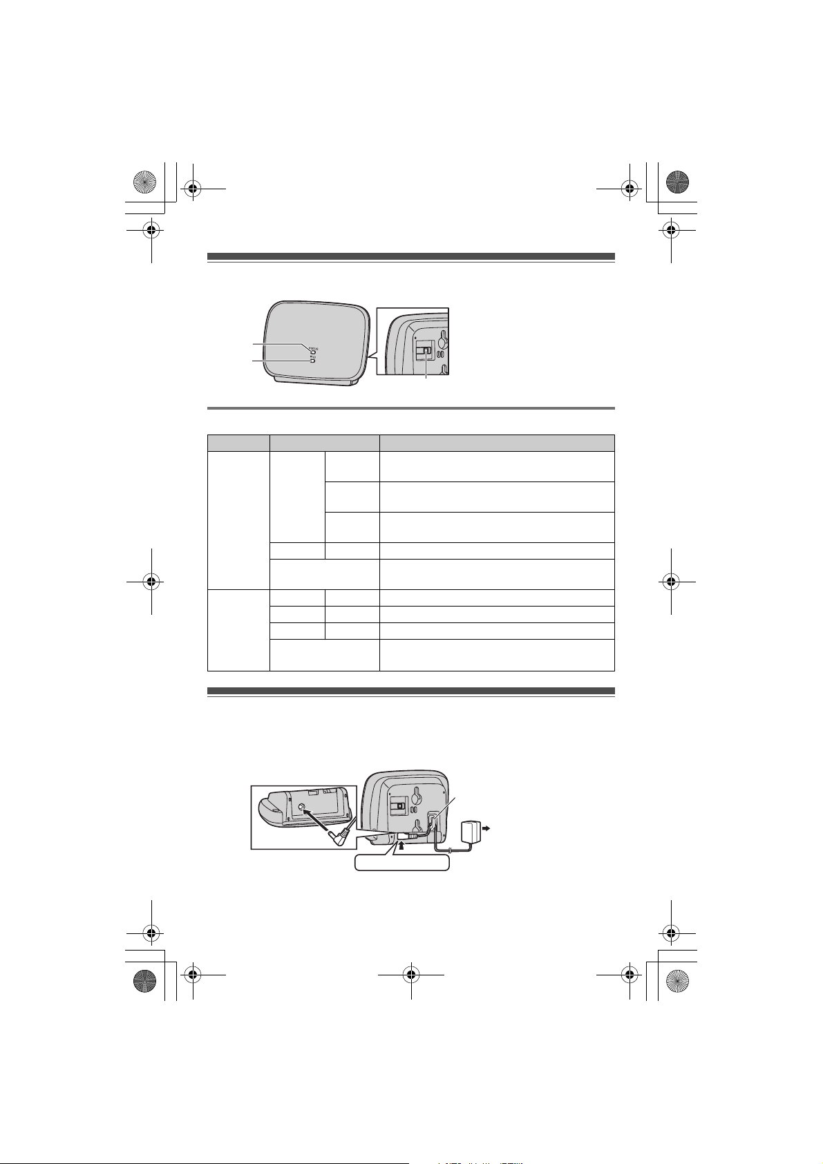
Controls
A STATUS indicator
B w indicator
A
B
C
Understanding the STATUS indicator and w indicator
Indicator Light status Meaning
STATUS
indicator
w
indicator
Green On LWithin base unit range. The unit is ready for
Flashing L1 handset is communicating with the base
Flashing
rapidly
Red On LOut of base unit range.
Off LThe power is off. (AC adaptor is not
Green On LSignal strength of the base unit is strong.
Amber On L Signal strength of the base unit is weak.
Red On LOut of base unit range.
Off LThe unit is not being used.
use.
unit through this unit.
L2 handsets are communicating with the base
unit through this unit.
connected properly.)
LThe power is off.
ID indicator
C {PROGRAM}
Installation
1 Connect the unit.
LUse only the supplied Panasonic AC adaptor PQLV219.
Hook
(120 V AC, 60 Hz)
Press plug firmly.
LWhen the unit is turned on, the STATUS indicator and w indicator light amber
for about 2 seconds.
– 2 –
 Loading...