

Page 1
EIA/REMOTE
PROGRAMMING
MANUAL
KX-T123211 D
ELECTRONIC MODULAR SWITCHING SYSTEM
’
Please read before use.
Page 2
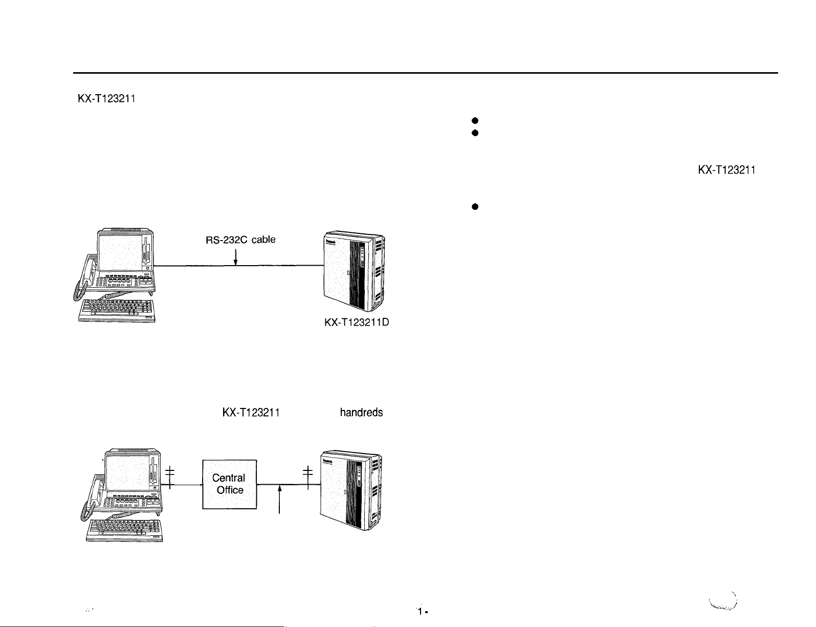
KX-Tl23211
reprogramming (Showing, Editing, Dumping so on) can be done by
using a RS-232C interface port or a MODEM (through a Central
Off ice) from the place where KX-Tl23211 D is set and far.
n
When use the RS-232C interface port (On-site Administration)
Programming or reprogramming can be done by connecting it to
KX-T123211 D at the same place as it.
Data terminal equipment
D EMSS has function that programming or
Preface
The Card which should be installed to KX-Tl23211 D consists of
n
the following cards.
0
Direct Inward System Access Cards KX-T123291
0
MODEM Card KX-T123296
If Outgoing Message is sent when a call is sent to
n
you will be able to confirm that the call arrived to the other party,
so this card is useful.
0
Outgoing Message Card KX-T123292
Data terminal equipment
n
We recommend a data terminal equipment provided with a display
(Example KX-D4985 Panasonic).
A data terminal which is not equipped with a display can print out a
data automatically, so this can be used, too.
KX-Tl23211
D,
n When use the MODEM (Remote Administration)
Programming or reprogramming can be done through a Central
Office from the place where
miles away.
Data terminal equipment
.;
KX-Tl23211
Telepone
D is in a few
Line
KX-T1232 11 D
handreds
7 -
1
‘Lit.- ;
--.,’
\
Page 3
Feature
Edit 1 Shqw
Program to KX-T123211 D newly or the preset programming
contents are displayed on the display of the data terminal
equipment and then confirm (by show mode) or change (by edit
mode) them.
Interactive Style
Showing or Editing of data is done with a conversation style like
that after one person ask, the other person answer.
Batch Style
After store the data which is preset or wish to change with a
floppy, the data can be transmitted to
program can be done.
When a data is entered at a time at the place where
KX-T123211 D is set, RS-232C interface port is used and when a
data is entered from far, send a data at a time after call the other
w-W
KX-Ti
23211 D at a time and
H
Dump
The preset program data in KX-T123211 D can be copied to the
floppy disk in a disk drive of a data terminal equipment.
n
System Working Report
The number of incoming calls, answered of incoming calls and
unanswered of incoming calls and the number of access
requested, access succeeded and access failed are reported.
’
l-2
I
In this Manual, the model No. KX-T123211 D is abbreviated to
KX-T123211.
I
Page 4
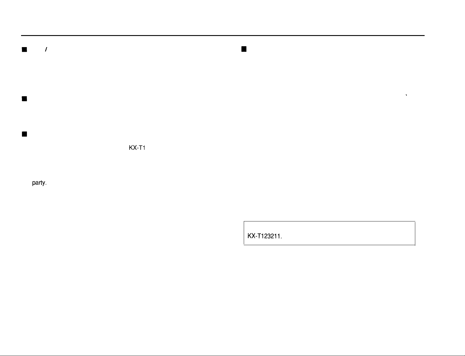
Contents
Outline of the Operation
Preparation
On-site Administration
Remote Administration
On-site / Remote Administration Start
On-site Administration Start
Remote Administration Start ....................... 3-4
On-site / Remote Administration Start Map ........... 3-5
On-site / Remote Administration End
On-site Administraion End
Remote Administraion End
On-site / Remote Administraion End Map ........... 3-7
To Edit the Data by “lntaractive Style” .................. 3-8
Editing or Programming
To Show the Data by “Interactive Style” ..............
Showing
....................................
.............................
..........................
........................... 3-3
...................... 3-4
.......................
........................
..........................
3-l
3-2
3-8
3-8
3-g
3-l 1
3-l
Format
SYSTEM
SYSTEM
SYSTEM
SYSTEM
SYCJ-EM
2
FEATURE-1
0
Extension Number Assignment-l (for Jack number 01 through 16)
FEATURE-2 . . . . . . . . . . . . . . . . . . . . . . . . . .
0
Extension Number Assignment-2 (for Jack number 17 through 32)
FEATURE-3 . . . . . . . . . . . . . . . . . . . . . . . . . .
0
System Speed Dialing Entry
FEATURE-4 . . . . . . . . . . . . . . . . . . . . . . . . . .
0
Date and Time Setting
0
Operator Assignment
0
Automatic CO Hold Using DSS Button
0
Day/Night Service Mode
0
Call Hunting
FEATURE-5 . . . . . . . . . . . . . . . . . . . . . . . . . .
0
Area Type Selection
0
CO Operator Call Boundary Class
. . . . . . . . . . . . . . . . . . . . . . . . . . .
5-l
5-3
5-4
543
543
To Edit or Show the Data by “Batch Style” ............ 3-13
To make the batch data
Edit / Show Mode Map
To Dump the Data
Dump Mode Map
To Dump or Clear the System Working Report (SWR)
System Working Report Map . . . . . . . . . . . . . .
Example of Programming
To edit the data by “Interactive Style”
with Remote Administration
The way of seeing table
...............................
........................
............................
.............................
. . . . . . . . . . . . . . . .
. . . . . . . . . . . 9 . . . . . . .
.
. .
. .
. .
. . .
. . . . .
. . . . .
3-15
‘$17
‘J-1
‘J-20
. . 3-21
3-22
4-l
4-3
0
Toll Restriction of System Speed Dialing
SYSTEM FEATURE-6
l Toll Restriction-Allowable Exchange Code Selection
8
2-1
SYSTEM
SYSTEM
SYSTEM FEATURE-9
FEATURE-7
0
Toll Restriction-Area Code Entry for Class 3
FEATURE-8
0
Toll Restriction-Exchange Code Entry for Class 5
0
Toll Restriction-Exchange Code Entry for Class 7
. . . . . . . . . . . . . . . . .
. . . . . . . . . . . . . . . . . . . . . . . . .
. . . . . . . . . . . . . . . . . . . . . . . . . 5-11
. . . . . . . . . . . . . . . . . . . . . . . . .
5-g
5-10
5-12
Page 5
SYSTEM FEATURE-10
0
Hold Time Reminder
0
Hold Recall Time Set
0
Transfer Recall Time
0
Call Forwarding Starting Time
0
Pickup Dial Delay Time
. . . . . . . . . . . . . . . . . . . . . . . . . .
5-13
OUTSIDE
0
0
0
0
0
LINE
FEATURE-1
. . . . . . . . . . . . . . . . . . . . . . . .
CO Connection Assignment
Dial Mode
(DTMF/PuIse/CalI
Blocking)
Host PBX Access Codes Assignment
Trunk Group Assignment
Automatic Designated CO Line Access
6-l
l CO to CO Duration Time Limit
0
Off Premise Extension (OPX)
0
Off Hook Call Announcement (OHCA)
l Call on Hold for Standard Telephone
SYSTEM
SYSTEM
FEATURE-1
0
SMDR Parameters
0
Incoming/Outgoing Call Selection for printing
0
Secret Speed Dial / One Touch Dial Printing
0
Duration Time Count Start Mode
0
External Paging Access Tone
0
DTMF Receiver Check
FEATURE-1
1
. . . . . . . . . . . . . . . . . .
2 . . . . . . . . . . . . . . . . . .
Direct Inward System Access (DISA)
SYSTEM
SYSTEM
FEATURE-13
0
Day/Night Service Mode (Starting Time)
. . . . . . . . . . . . . . . . . .
FEATURE-90 . . . . . . . . . . . . . . . . .
0
RS-232C Communication Parameters
. . .
. . .
. 5-15
. 5-19
. 5-20
0
CO Mode (Normal / Direct In Line / Direct Inward System
Access) Assignment
0
Pause Time Assignment
0
Hookswitch Flash Timing
0
Calling Party Control (CPC) Signal
0
Disconnect Time
CPC
Signal
Detect Time
OUTSIDE LINE FEATURE-2M
0
Flexible Outward Dialing Assignment (Day/Night Mode)
OUTSIDE LINE
0
Flexible Ringing Assignment (Day/Night Mode)
FEATURE-4/5
OUTSIDE LINE FEATURE-fj/T
0
Delayed Ringing Assignment (Day/Night Mode)
EXTENSION
0
Extension Group Assignment
0
Service Class Assignment of Toll Restriction
0
Extension Name
0
Account Code Input Mode
FEATURE-1
. . . . . . . . . . . . . . . . . . . . . . . .
. . . . . . . . . . . . . . . . . . . . . .
. . . . . . . . . . . . . . . . . . . . . . 6-5
. . . . . . . . . . . . . . . . .
. . . . . . . . . . . . . . . . . . . . . . . . . . .7-l
G-3
6-4
..+343
0
Call Transfer to Outside Line
0
Call Forwarding to Outside Line
0
Executive Override
0
Do not Disturb Override
2
--2
Page 6
Contents
(cont.)
EXTENSION
0
Flexible CO Button
DOORPHONE FEATURE-l/2
0
Ringing Assignment of Doorphone (Day/Night Mode)
DSS CONSOLE
0
Paired Telephone Assignment for DSS Console
DSS CONSOLE
@
DSS Console 1 or 2-Flexible DSS Button
CLEAR FEATURE
Programming Table
FEATURE-2 .......................... 7-3
.......................
FEATURE-1 .......................
FEATURE-2/3
.....................
..............................
.............................
Supplement
Kinds of Setting Mode Command and Prompt .......
Disposal
Note
“HLP” Command
Main Command
DisposalExecuteCommand
Style
.......................................
...............................
.............................
System
........................
.....................
8-l
g-1
9-2
10-l
11-l
12-1
12-l
12-l
12-l
12-2
12-2
The way to enter Disposal Execute Command .......
12-3
Page 7
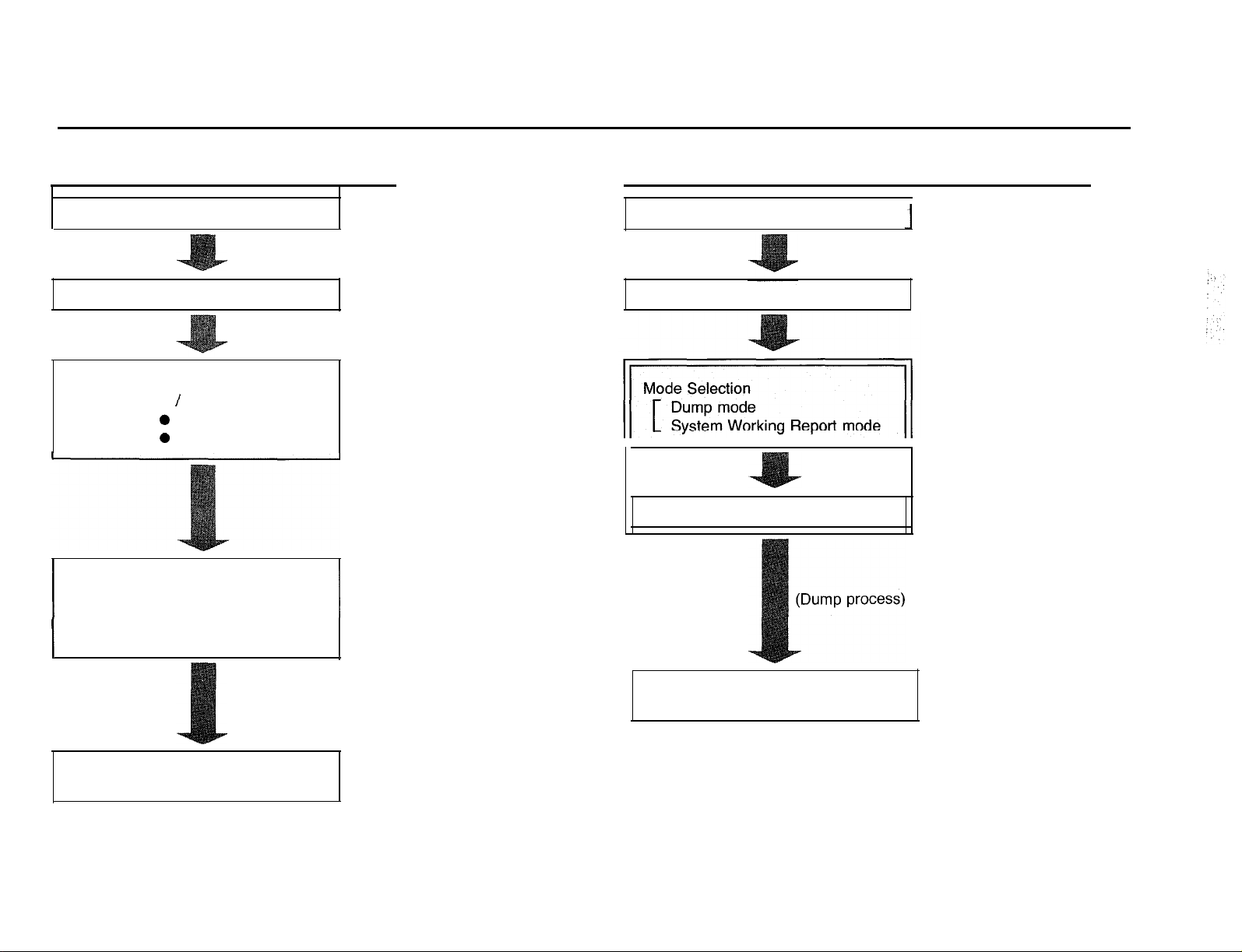
Outline of the Operation
To edit or show the system program
Preparation See pages 3-2 and 3-3. Preparation See pages 3-2 and 3-3.
Start
Mode Selection
Edit / Show mode
0
Interactive Style
0
Batch Style
1
Programming 1
See page 3-4.
See pages 3-8
through 3-17.
See pages 5-1
through 10-l.
To dump the system data or system working report
Start
Item Selection
See page 3-4.
See pages 3-18
through 3-22.
End
See page 3-6.
End
See page 3-6.
Page 8
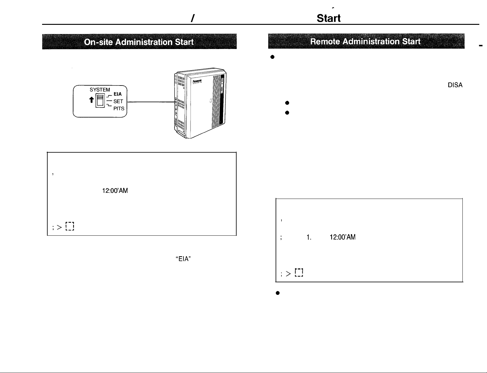
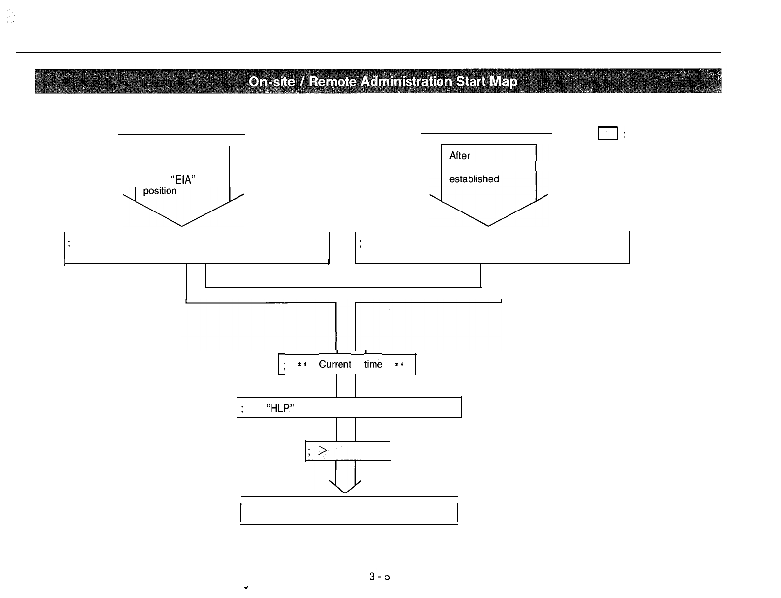
On-site / Remote Administration Start
1. Set the System Program Switch on the KX-Tl23211 to the “EIA”
position.
0
Be sure the System Program switch on the KX-Tl23211 is set to
the “SET” position.
1. Make a call to the line which is beforehand programmed as a
Line on the KX-Tl23211.
0
Dial tone will be heard.
0
If the Outgoing Message Card is installed to KX-Tl23211,
Outgoing Message will be heard instead of dial tone.
The display on data terminal will show ;
2. Dial the Remote Security Code (70000 through 79999).
You will hear the answer carrier tone.
; Welcome to KX-Tl23211 on-site administration
I
; ** Jan. 1. 1988
12:OO’AM
ver 2.0 Panasonic CO., LTD
**
3. After the answer carrier tone, set the on-line mode on your data
terminal equipment.
l The display on data terminal will show.
; The “HLP” displays command informations ; Welcome to KX-Tl23211 remote administration
1
ver 2.0 Panasonic CO., LTD
DISA
n When you set the programming switch to the
“EIA”
position, the
system will stop its own normal exchanging operations, disconnect
all the current calls, and connect same extensions to CO lines
directly with the power failure transfer feature.
CO1 will be assigned to extension of jack number 01
CO2 will be assigned to extension of jack number 02
CO5 will be assigned to extension of jack number 09
CO6 will be assigned to extension of jack number 10
CO9 will be assigned to extension of jack number 17
CO1 0 will be assigned to extension of jack number 18
3-4
3-2
;
** Jan. 1. 1988
;
** Jan. 1. 1988
12:OO’AM
12:OO’AM
**
**
; The “HLP” displays command informations’; The “HLP” displays command informations’
l---d
l---d
; > L-1
; > L-1
0
Whenever you don’t know which commands should be entered next,
press “HLP” and Carriage Return Keys. You will find the next
command (See page 12-l).
Page 9
On-site administration
Set the System
Program Switch
to the
“EIA”
;
Welcome to KX-T123211 on-site administration
I I
ver 2,0 Panasonic CO., LTD
Remote administraion
communication
;
Welcome to KX-T123211 remote administration
;
I
ver 2.0 Panasonic CO., LTD
I:
Indication on
display of data
terminal .
eqipment
;
The
.
1; ** CurCent ;ime **
“HLP”
displays command informations
(Process of Operation)
1
Page 10
c
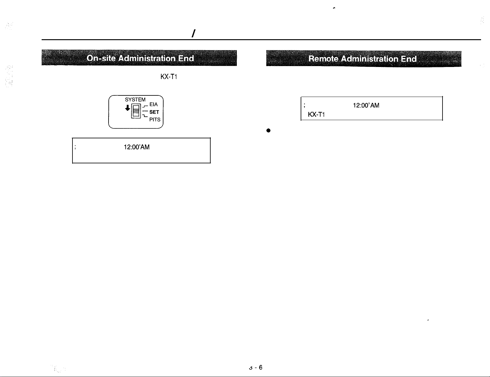
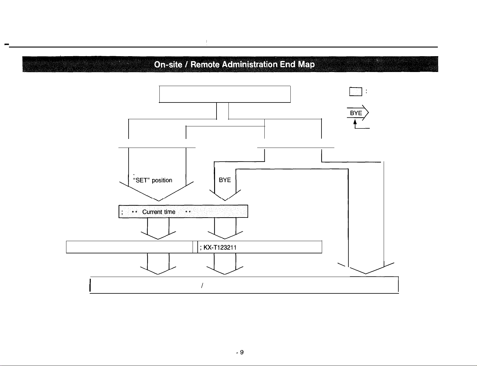
On-site / Remote Administration End
Return the System Program Switch on the
“SET” position from the “EIA” position
;
** Jan. 1. 1988
; KX-T123211 on-site administration end
12:OO’AM
**
KX-Ti
23211 to the
Make your data terminal equipment off-line or hang up or enter
“BYE” command.
when you enter the “BYE” command;
;
** Jan. 1. 1988
;
KX-Ti
23211 remote administration end
0
If carrier tone from the data terminal equipment stop while data
communication, the operation with Remote administration will
finish.
12:OO’AM
**
3-6
Page 11
On-site administration
Return ‘the
System Program
Switch to the
; KX-Tl23211 on-site administration end
(Process of Operation)
I
; KX-T123211
remote administration end
Remote administration
0:
Indication on display of
data terminal equipment
Remote administration
end command
L
Data
terminal
equipment
off-line,
hang up or
Carrier
tone stop
(On-site / Remote Administration End)
-9
\
Page 12
c
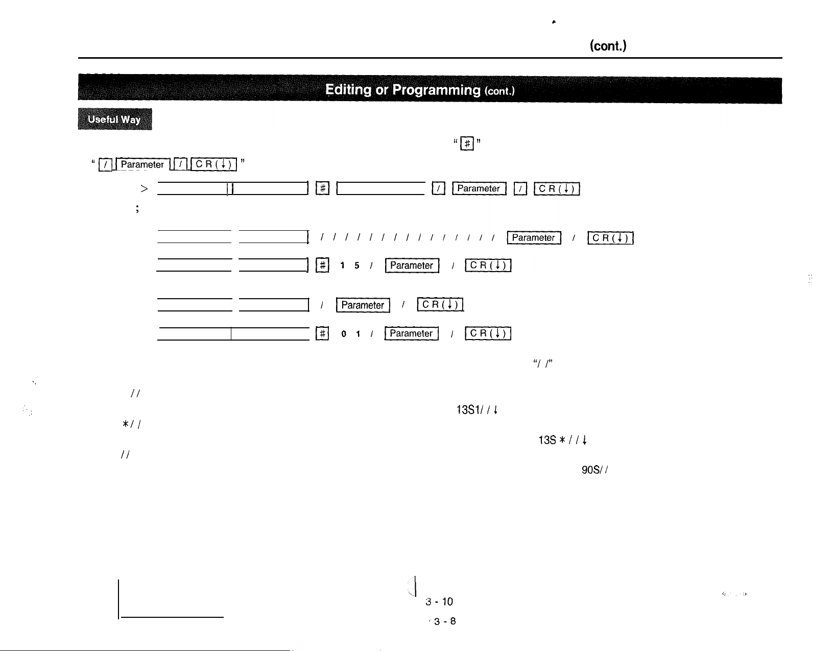
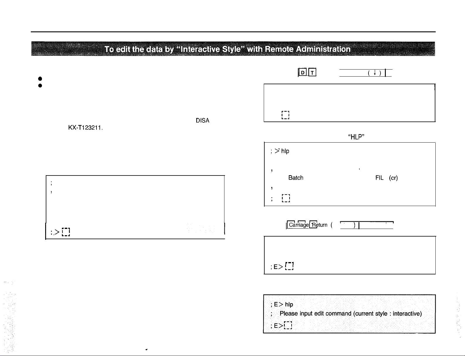
To Edit the data by “Interactive Style”
n If you want to change just one parameter of many parameters, you may press
“ 1/1 m
; E > Main command 1 1 Subcommand
Example
;
In case of changing the 15th
; E > Main command
or
; E > Main command
In case of changing the 1st
; E > Main command
or
; E > Main command
111 JcR(1)I ”
key..
ICII
Subcommand
Subcommand
1
JpJ15l~l/
SubcommandI
Subcommand
I#I 011
# Parameter number
llll1llll
piiEzq
IIcR(1)I
)j
/
(cont.)
I‘ I#I ”
key and the parameter number and then press
IcRcr,l
n
In case you want to show the setting contents with Edit Mode without changing to show Mode, enter “/ /” after command
.,
as follows.
MS // 1 (To see all parameter with Subcommand S of Main Command)
,‘.
.:
To see the Starting Time of Day/Night Service Mode on Monday, press
M
*:/ /
1 (To see all parameter with Subcommand of Main Command at a time)
To see the Starting Time of Day/Night Service Mode on Sunday through Saturday, press
M // 1
(To see all parameter with Main Command)
13Sl/ / 1
.
13s t / / 1
To see the Parity, Carriage Return for a New Line, Word Length, Stop Bit Length and Baud Rate, press
.3-B
.
90% /
1 .
Page 13
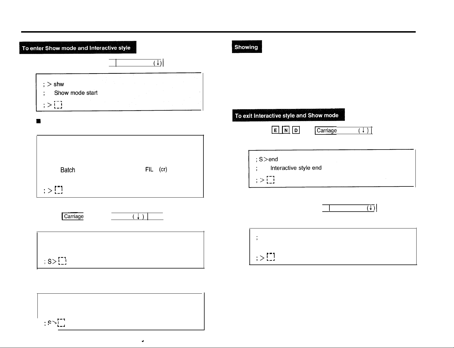
To Show the Data by “Interactive Style”
1. Press the
Rl
If you wish to know the effective commands which can be
used on this mode, enter the “HLP” command.
; > hlp
;
,
,
; > !.,.!
2. Press the
q q q
Select the style
Interactive . . . . . . . . . . . . . INT (cr)
Batch
. . . . . . . . . . . . . . . . . .
Mode end . . . . . . . . . . . . . .
b--v
fl w
q
Return ( 1 ) 1 key,
and 1 Carriage Return ( 1 ) 1 key.
andICarriage
FIL (cr)
END (cr)
3. Enter the commands corresponding to the feature that you want to
know. (See page 3-12)
4. To see another data, repeat step 3.
5. Press the m w
6. Press the
q q q
IDI
and
lCarriage
Return ( 1 ) 1 key.
and 1 Carriage Return ( 1 ) 1 key.
; > int
;
Interactive style start
I--,
; s> 1-1
q If you wish to know the effective commands which can be
used on this mode, enter the “HLP” command.
; S> hlp
;
Please input show command (current style : interactive)
r-7
:,=\I
I
L
‘-.I
.,
3 -- I I
;
> end
;
Show mode end
l--q
; > L-1
Page 14
L
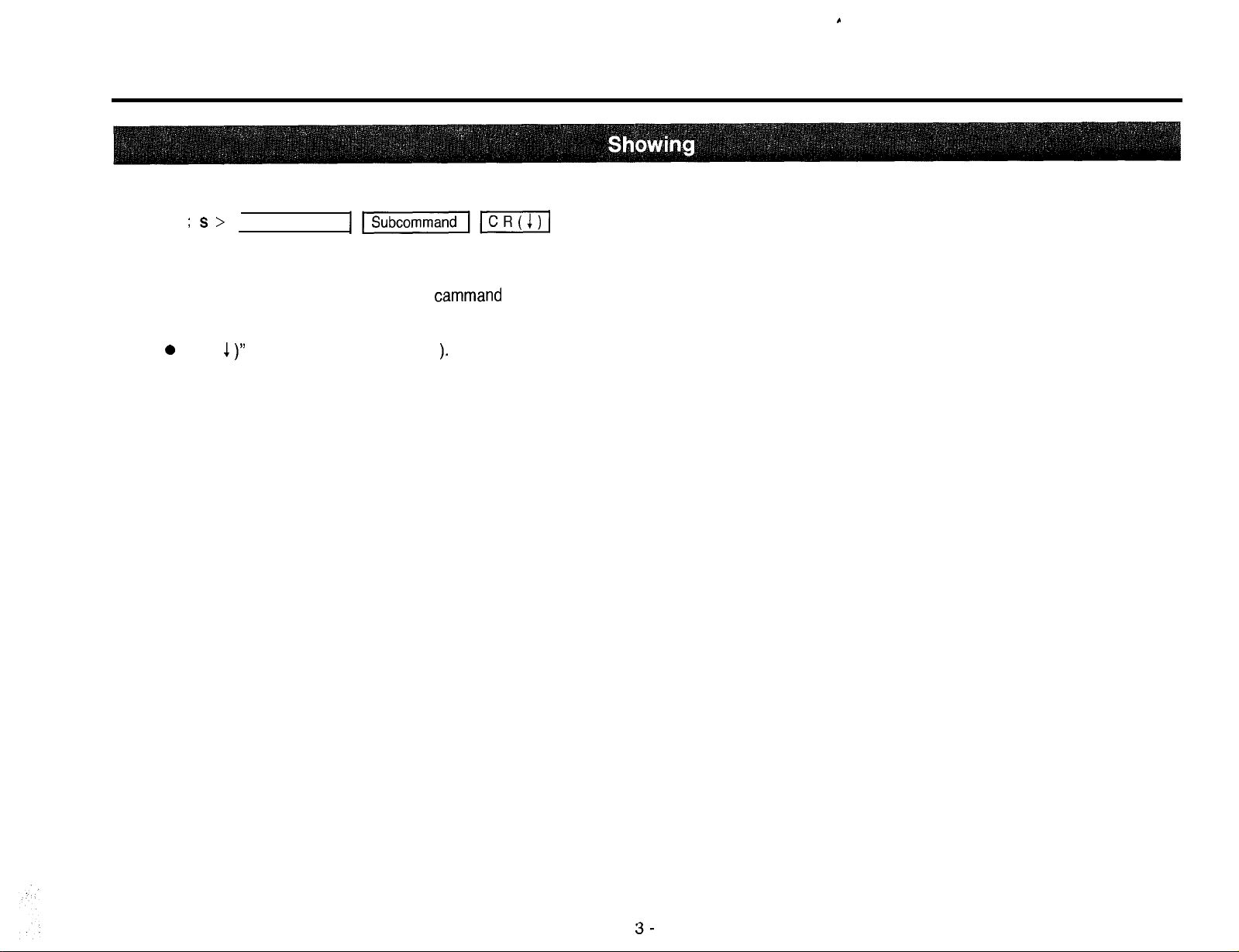
To Show the Data by “Interactive Style”
Enter the command corresponding to the feature that you want to show according to this format.
; S >
Main command
The feature names or the data of Main
them according to this table, please.
0
“CR ( 1 )” means Carriage Return ( 1
Ipi%izal~ICR(I)I
cammand
and Subcommand that you want to show are explained on page 5-l through 10-1, so enter
).
(cont.)
3-
12
Page 15
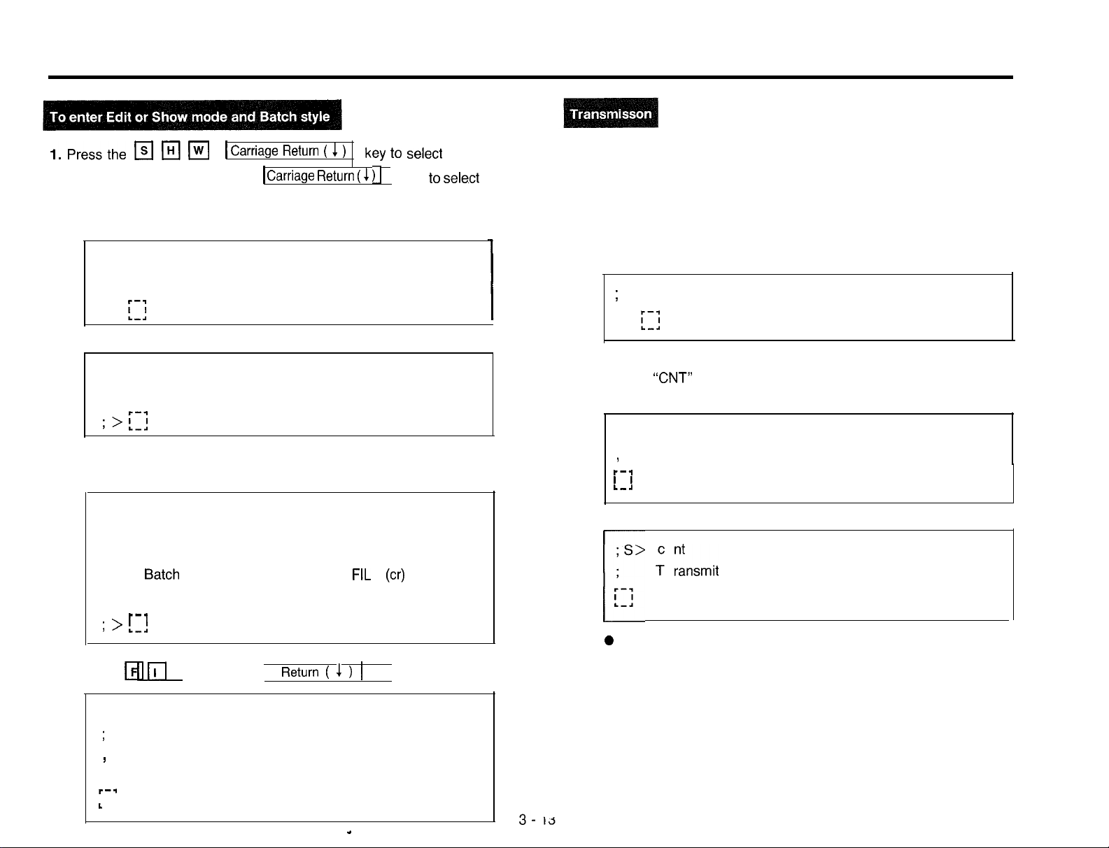
To Edit or Show the Data by “Batch Style”
l.Pressthem(H(m
Show mode, or
the Edit mode.
When Edit mode:
; >edt
;
Edit mode start
; >
f;j
When Show mode:
; > shw
; Show mode start
n If you wish to know the effective commands which can be
used on this mode, enter the “HLP” command.
; > hlp
;
Select the style
I--,
; > !-!
q q q
Interactive
Batch
. . . . . . . . . . . . . . . . . .
Mode end . . . . . . . . . . . . .
Carriage Return ( 1 )
1
1
Carriage
. . . . . . . . . . . . . .,INT (cr)
Return
key
(
1 )I
FIL (CT)
END (cr)
to select
key
the
to select
3. Transmit the batch data to the KX-T123211.
The system data will be shown on the display.
4. When transmission of system data has been finished, the display
will show the following.
n If “EOD” data is programmed in batch data;
;
Batch style end
; >
[:I
I
If enter
When Edit mode:
When Show mode:
r
0
“CNT”
command;
; E> cnt
Transmit the next batch data
1
r--l
I I
I.-.!
f
“nsmit
To show or edit another data, repeat step 3.
the next batch data
2. Press the m rl
1 Carriage
; > fil
;
Batch style start
<Transmit the batch data>
I
I--.
I
L
q
and
Return ( 1 )
1 key.
.
Page 16
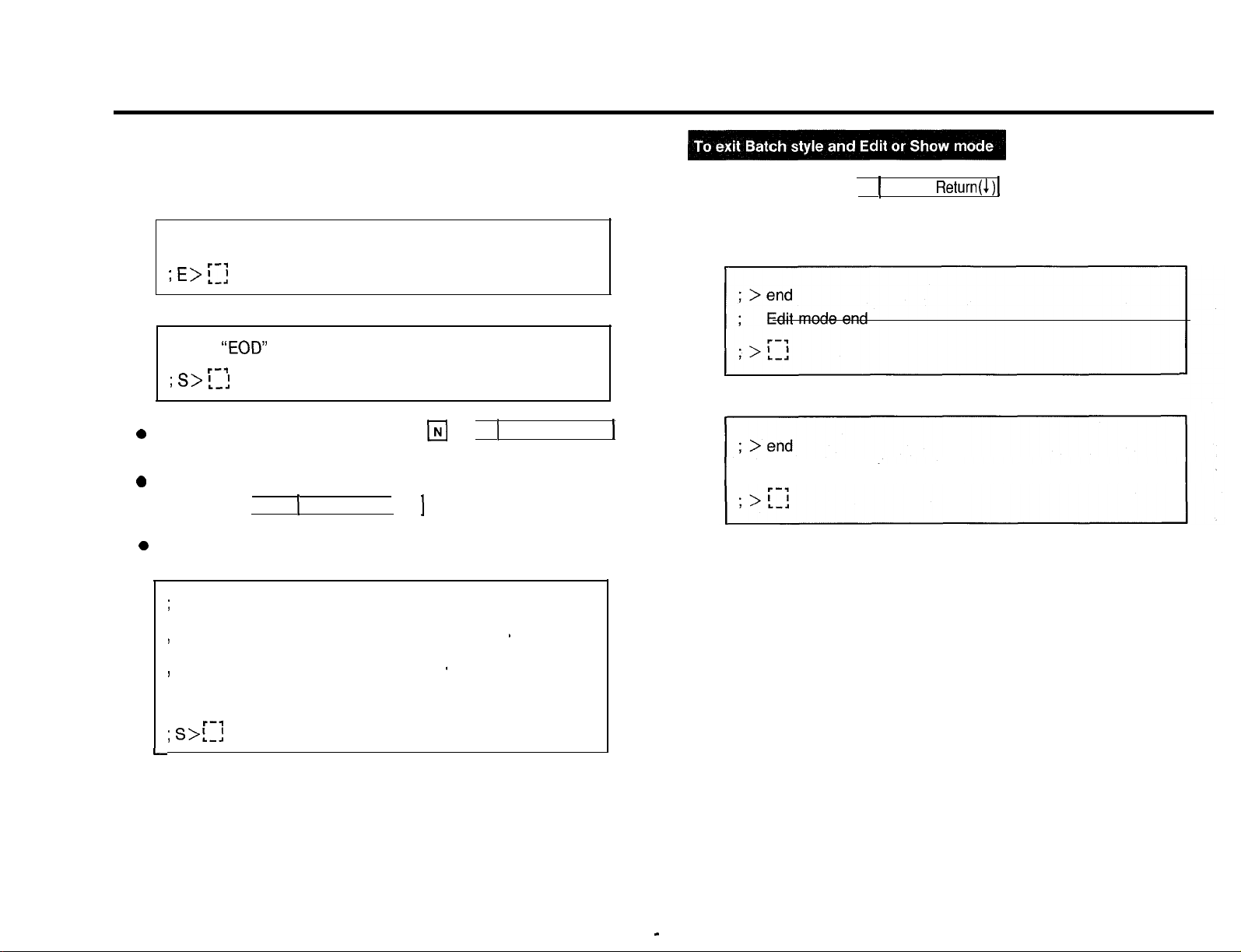
To Edit or Show the Data by “Batch Style”
n If “EOD” data is not programmed in batch data, the display will
show the following after two minutes.
When Edit mode:
5. Press
q q q
1
Carriage Return ( 1 ) 1key.
(cont.)
; None “EOD” In batch data
r-3
; E> ‘.-;
When Show mode:
; None
; s> 1-J
0
To end the batch style, press
key.
0
To continue the batch style, press the
q q q
0
If you wish to know the effective commands which can be used on
this mode, enter the “HLP” command within two minutes.
;
Select the command (current style : batch)
f
“EOD”
In batch data
l---l
q
R
q
1
Carriage Return ( 1 )
1
Carriage Return ( 1 ) 1 key and repeat step 3.
Batch mode end . . . . . . . . . . . . . . . . . *END (cr)
Next batch data
. . . . . . . . . . * . . . . . . .ICNT (cr)
When Edit mode:
When Show mode:
1
1 ; Show mode end
; s>!.-l
I--*
3 - 14
Page 17
1. Set a floppy disk to the drive of a data terminal equipment.
2.
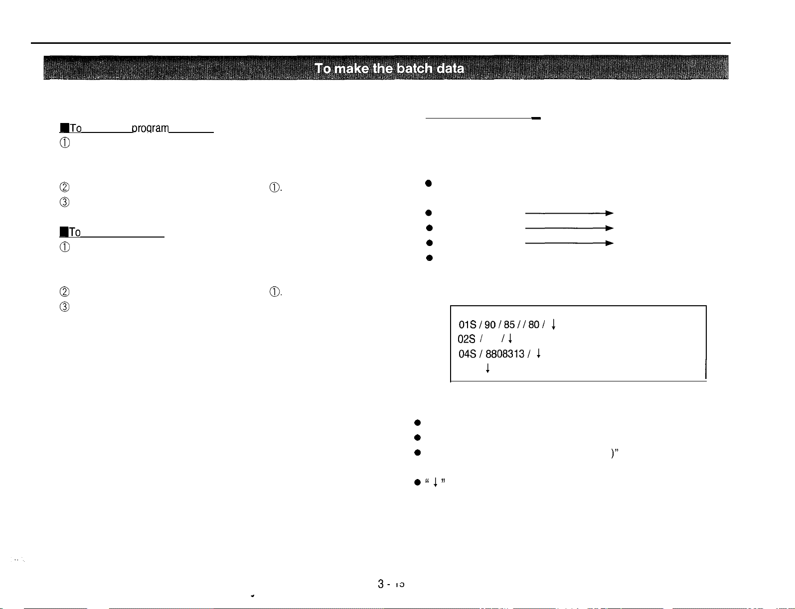
UTo
chanqe or
0
Enter the command (Main command, Subcommand) and
parameter corresponding to the feature that you want to
change as the way on page 3-9 “Editing or Programming”.
0
When change the other feature, repeat step
O
After entering all the data, enter “EOD”.
UTo
confirm a data
0
Enter the command (Main command, Subcommand)
corresponding to the feature that you want to confirm as the
way on page 3-12 “Showing”.
0
When confirm the other feature, repeat step
a
After entering all the data, enter “EOD”.
proqram
a data
0.
0.
Example :
q
Change or program
Make the data to edit as follows and memorize the data to the
floppy disk.
0
To change the Extension number which is assigned to jack
number 01 into 190.
e
Jack number 02
0
Jack number 04
0
Jack number 17
e
To set date into Aug. 31’ 88 (Wednesday)
Enter them to the data terminal equipment as below
_
-
-
-
Extension number 185
Extension number 180
Extension number 165
3. Make the floppy memorize the entered data.
3- 13
OlS/90/85/180/
02s /
65 I
1
04Sl8808313l 1
EOD
1
Note
0
EOD is surely made in the end of batch data.
e
One line up to 78 digits.
0
Be sure to press the “Carriage Return ( 1 )” key in conclusion of
one data.
0 “ 1 ”
means Carriage-Return.
1
Page 18
c
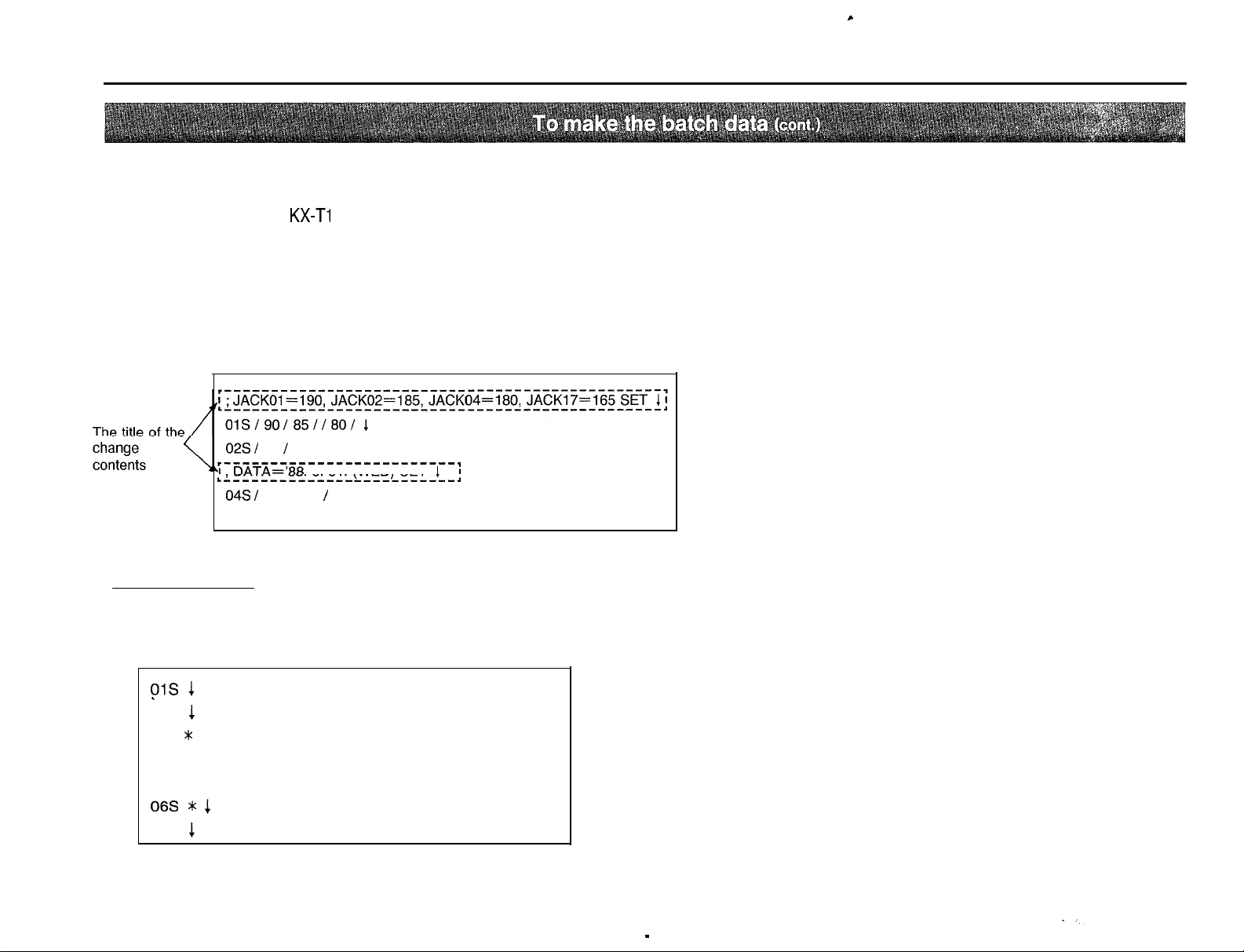
To Edit or Show the Data by “Batch Style”
(To recognize the made data)
If
q
batch data is sent to the
equipment.
If the title of the change contents are entered in the line as following,
it will be useful when use it later because of the recognition of the
contents.
is entered in the first line, the line will not be executed when a
KX-Ti
23211 from a data terminal
02s I
65 I 1
r-------------------------,
‘1. DATA=‘88.
rl------------------------r
04s I
8808373 I 1
EOD 1
8. 37. (WED)
SET11
(cont.)
n
Confirmation
To show the data of SYSTEM FEATURE-l through 6
(see page 5-1 through 5-9)
Make the data code as follows and memorize the data code to the floppy disk.
ys 1
02s
1
03s * 1
04s 1
05s 1
06s * 1
EOD
1
3 - 76
Page 19
;>
I-
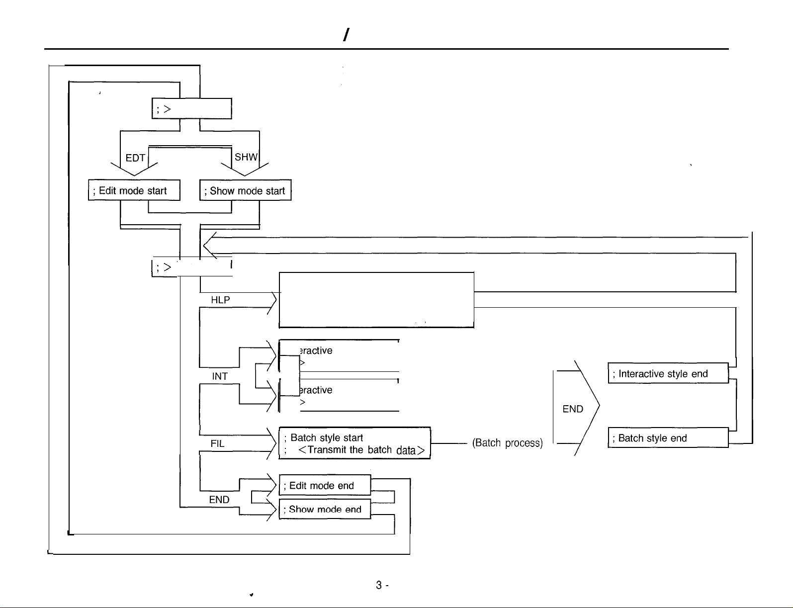
Edit / Show Mode Map
; Select the style
;
Interactive . . . . . INT (cr)
;
Batch . . . . . . . FIL (cr)
;
Mode end . . . . . END (cr)
j j Ftyctive
INT
/ j lgactive
s
‘7))
.0
b
r
p
j
B~~~~$fi~~~ batch data> I-
style start
style start
3-
I
I/
(Interactive process)
(Batch process)
Page 20
1
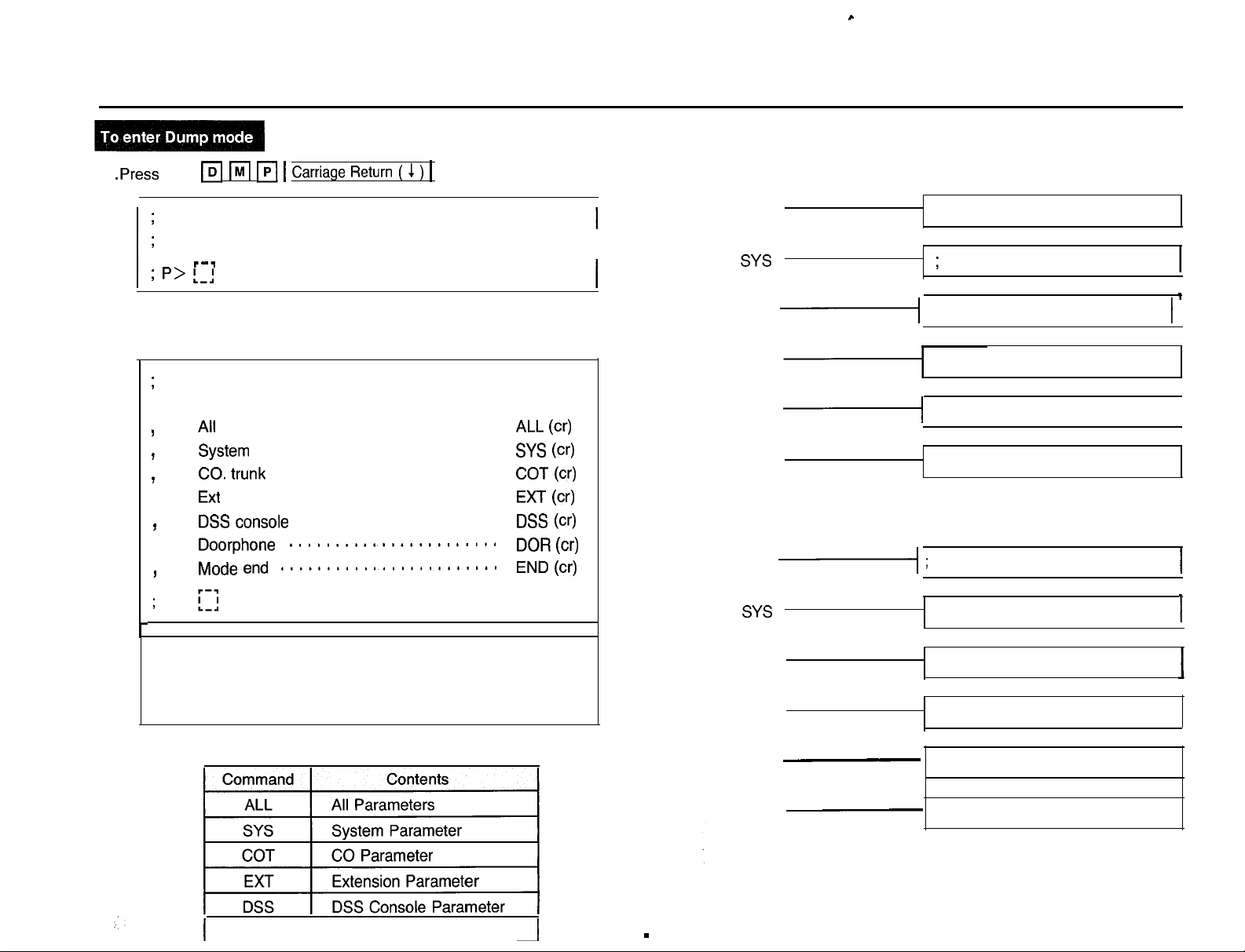
.Press the
m m IpI
1
Carriage Return ( 1 )
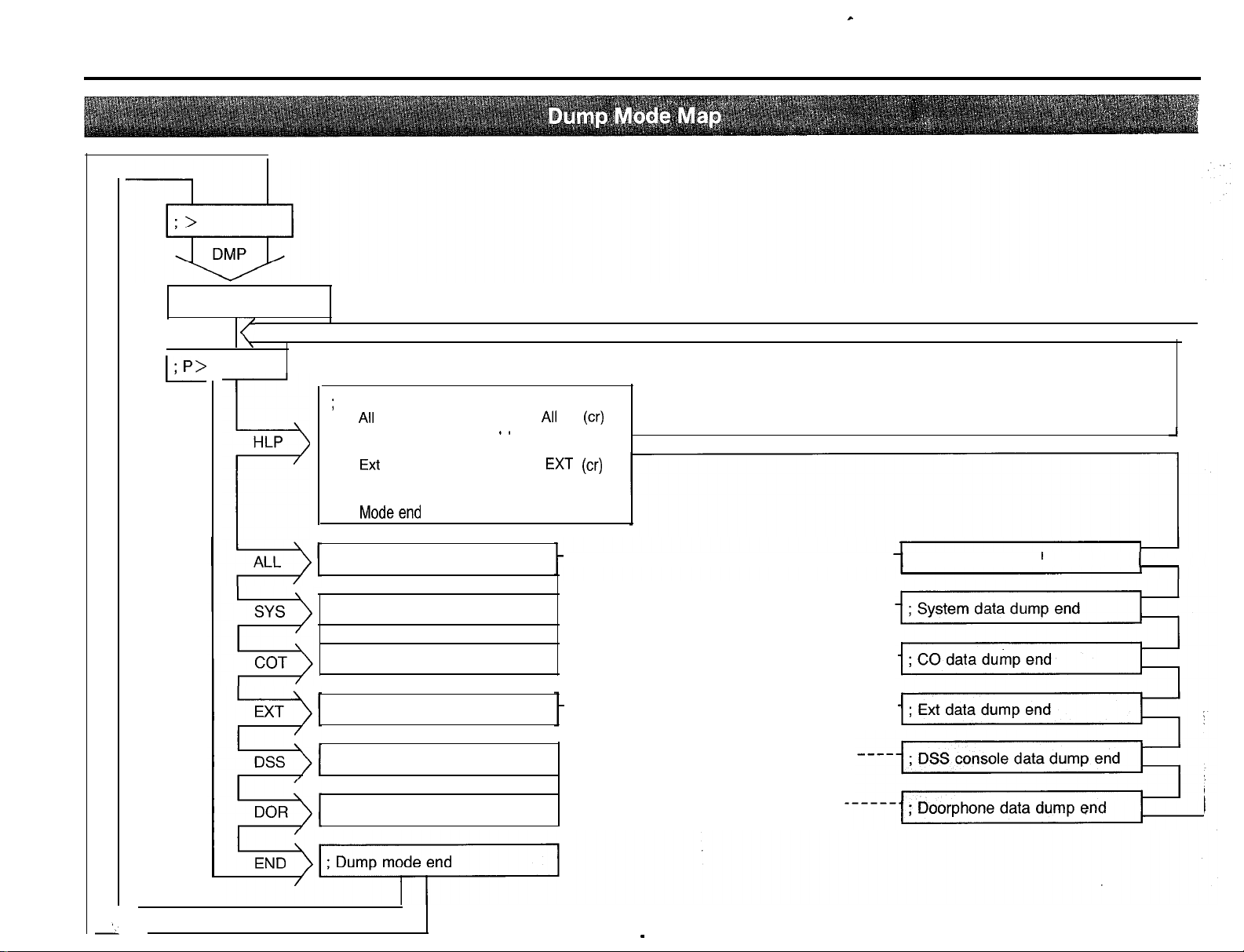
To Dump the Data
1key.
c
n
The first message will be displayed as follows when each
command is entered.
;
> dmp
I
;
Dump mode start
I
I
l---l
; p> L-1
n If you wish to know the effective commands which can be used on
this mode, enter the “HLP” command.
;
P> hlp
; Select the item
..............................
AlI
I
System SYS (cr)
F
CO. trunk
I
Ext
,
DSS console
I
Doorphone DOR (CT)
.
Mode end END (cr)
I
;
P>
[;I
L
2.
Before input of the following commands, set floppy disk to the
data terminal equipment so that the data terminal equipment
can start recording.
..........................
........................
..............................
.....................
.......................
........................
ALL (cr)
COT (cr)
EXT (cr)
DSS (cr)
ALL
I
SYS
COT
-1
EXT ; Ext data dump start
DSS
-1
DOR
; All data dump start
;
System data dump start
; CO data dump start 1
; DSS console data dump start
; Doorphone data dump start
1
I
n The following message will be displayed when Dump is finished.
ALL
-1
SYS
COT
EXT
; All data dump end
; System data dump end
; CO data dump end
; Ext data dump end
I
Press the command of the parameter that you want to dump.
I
DOR
Doorphone Parameter
I
I
3
DSS
-
DOR
-
18
-
;DSS console data dump end
;Doorphone data dump end
Page 21
To Dump the Data
(cont.)
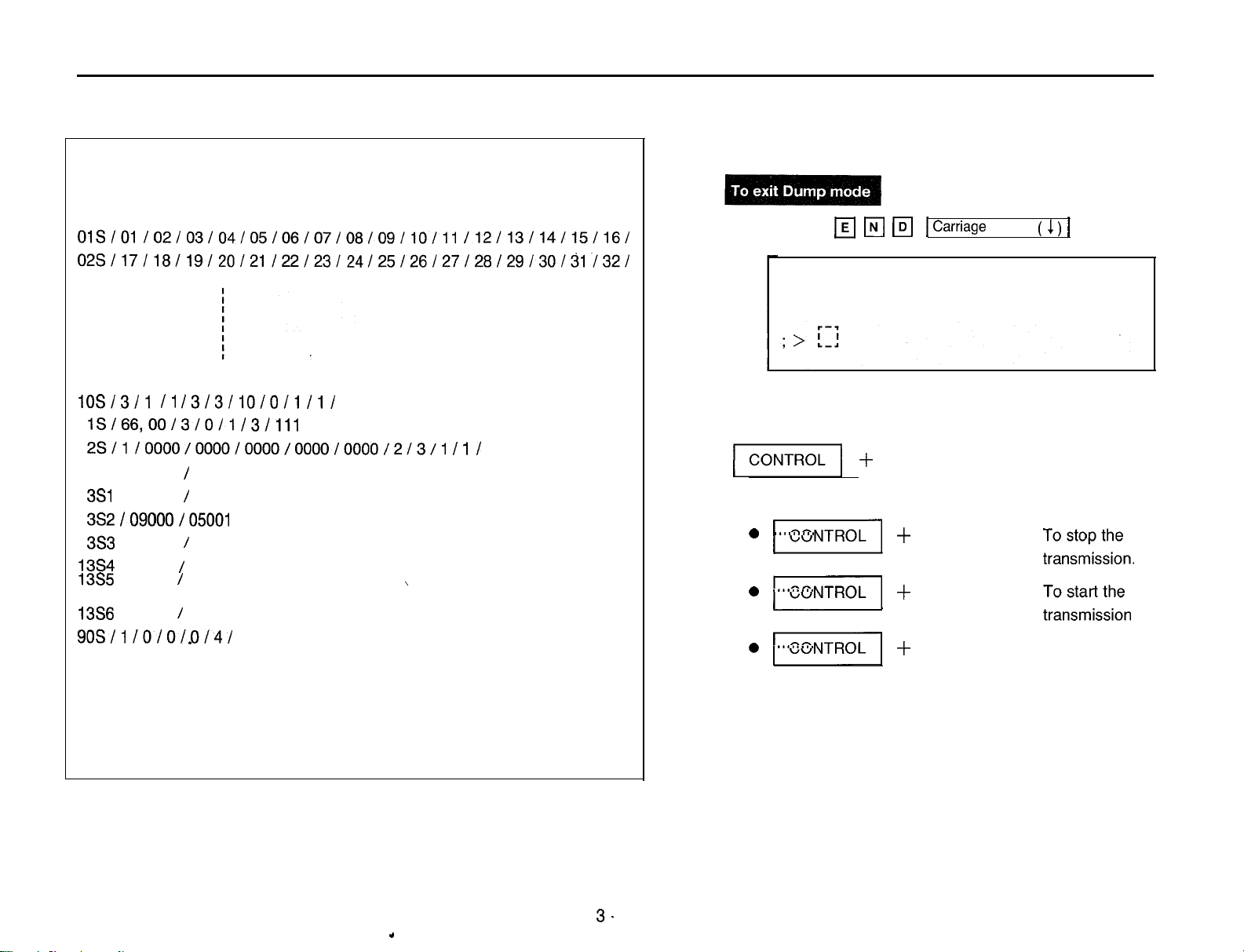
Example; When dump System parameter
; P>sys
; System data dump start
OlS/Ol /02/03/04/05/06/07/08/09/10/11
02S/17/18/19/20/21/22/23/24/25/26/27/28/29/30/31/32/
lOSl3Jl I1 /3/3/10/0/1/11
1
lSl66,OOJ3JOJl J3Jlll J
1
2S/1/0000/0000/0000/000010000/2/3/1
1
3so
I 09000 /
1
3Sl
J 09000 /
1
3S2
/09000/05001
1
3S3
J 09000 /
13S4J09000/05001
13%I09000/05001
13S6J09000/05001
9OSJl JOlOJ.OJ4J
EODEOD
05001
05001
05001
I
J
J
I
J
J
J
\
/12/13/14/15/16/
JlJ
3. To dump another data, repeat step 2.
4.
Press the
; P> end
n
II
to control the transmission from the KX-T123211.
0
II
.........
0
m
.........
0
m
.........
w
Iq m1Carriage Return
Dump mode end
+
q , q , q
-I-
To stop the
q
+
q
+
q
keys
keys
keys
( 1 )1key.
keys are used
tTb$gpU&
-L&z&~t~~~
process.
; System data dump end; System data dump end
; P>; P>
.
3.
Page 22
c
; Dump mode start
I
I/
I
I
; P>
l-
I\
HLP
F
To Dump the Data
;
Select the item
.
A,,
. . . . . . . . . . , . . . .
;
System . . . . . . . ‘. . . SYS (cr)
;
CO. trunk
.
Ext
;
DSS console
;
Doorphone
;
Modeend
; All data dump start
........... COT (cr)
...............
........ DSS (cr)
..........
.......... END (cr)
(cont.)
(cr)
A,,
EXT (cr)
DOR (cr)
---- (All data dump process) ------------ ; All data dump end
1
; System data dump start ----- (System data dump process)
; CO data dump start
; Ext data dump start
; DSS console data dump start -----
; Doorphone data dump start . ----- (Doorphone data dump process)
----- (CO data dump process) ------------
---- (Ext data dump process) ------------
(DSS console data dump process)
3 - 20
--------
Page 23
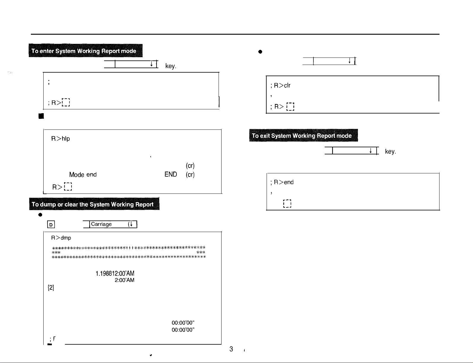
To Dump or Clear the System Working Report (SWR)
1.
Press the
;
> rpt
;
; R>f:;
1
If you wish to know the effective commands which can be used
on this mode, enter the “HLP” command.
;
; R>
l-
q q q
System working report mode start
R>hlp
Select the item
SWR data dump . . . . . . . . . . ’ . DMP
SWR data clear . . . . . . . . . . . . CLR
Mode end
i;j
. . . . . . . . . . . . . .
1
Carriage Return (
1
)
1
key.
END
(cr)
(cr)
(cr)
0
To Clear the System Working Report, press the
q q q
; R>clr
SWR data clear end
5
; R> [:I
3. Press the
q q q
; R>end
System working report mode end
I
1
Carriage Return (
1
) 1key.
1
Carriage Return ( 1 )
.
I
key.
1
2. 0To dump the System Working Report, press the
IDI
q q
;
R>dmp
****:+:*:i;:+::+:
:+::*:*
*:**:*::+:t::+::*z+x+:t:*:*::*h*::+:~::
[I] Date of record
Start : Jan.
End : Jan. 1.1988
[2] Incoming calls
CO-01: Number of incoming calls . . .
;r
-
ICarriage Return ( 1 ) 1key.
:+::+::+::+::+::+:
*:*:+::+::+::+T:+::+:
System working report
+.*:+::+::+::+::~*::+~+::~:+::+::~:+::~
1.198812:OO’AM
Number of answered calls . . . .
Number of unanswered calls . . .
Percentage of answer
Average ring time
Average duration . . . . . . . . . . .
+ + + ~..+..+,.+..~:+::+::i::t:~:+:+::+::+:‘t::~~t:jt:*:~:W:+::t’:+:
*:
*:.
z+t *::+::+::+::+::+:‘+-:+::t:‘)::+::~:+::+::~:+::+::+:
2:OO’AM
. . . . .
. . . . . . . . . :
:
:
:
:
:
0
0
0
0%
0O:OO’OO”
0O:OO’OO”
:*:+::*
; >
[I]
Page 24
c
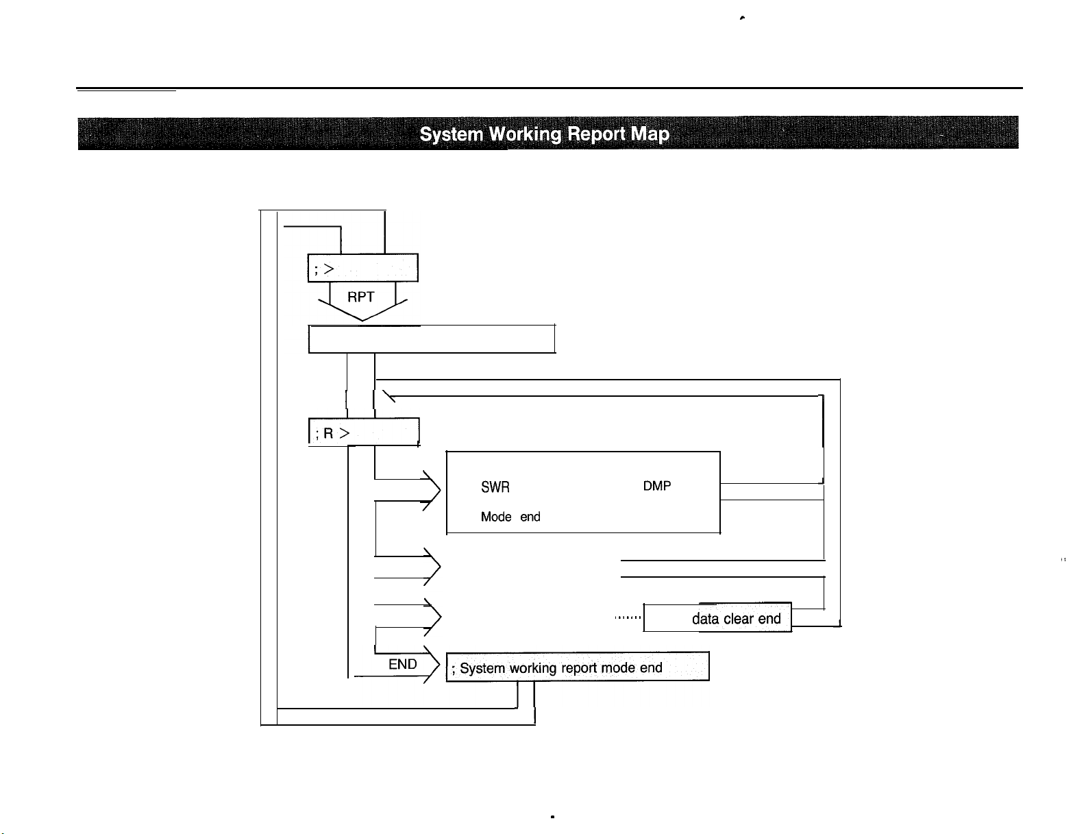
To Dump or Clear the System Working Report
; System working report mode start
I I’
I:R>
1
(cont.)
1
; Select the item
HLP
DMP
I
CLR
;
;
.,Mode en,-J
(SWR data dump process)
(SWR data clear process)
*
System working report mode end
=a
DMP
SWR
data dump . . .
SWR data clear . . . . . . . . CLR (cr)
. . . . . .
I......
-
22
(cr)
END (cr)
; SWR
J
”
d
Page 25
Example of Programming
n Installation of the following optional cards are necessary.
0
Direct Inward System Access Cards KX-T123291
0
MODEM Card KX-T123296
n
Preparation
See pages 3-2 and 3-3.
1. Make a call to the line which is beforehand programed as a
line on the
2. Dial the Remote Security Code (70000 through 79999).
3. After the answer carrier tone, set the on-line mode on your data
terminal equipment.
KX-T123211.
;
Welcome to KX-T123211 remote administration
I
; **Current time**
; The “HLP” displays command informations
ver 2.0 Panasonic CO., LTD
DISA
r--l
I
:>r !
I . ---
4. Press the
5. Press the 1 I I I N 1
I
q
I
; > edt
;
; >
n If you wish to know the effective commands which can be
used on this mode, enter the
; Yhlp
;
I
,
I
;
>
; > int
;
; E> t-1
Id Fi
1 Carriage Return ( 1 ) 1 key.
Edit mode start
[I]
Select the style
Interactive
Batch
. . . . . . . . . . . . . . . . . .
Mode end . . . . . . . . . . . . . . .
[;I
jcarriage Return (
Interactive style start
r--l
and
. . . . . . . . . . . 1 . .
ITI
1 ) 1 key.
and
“HLP”
command.
INT (cr)
FIL (CT)
END (cr)
n If you wish to know the effective commands which can be
used on this mode, enter the “HLP” command.
Page 26
Example of Programming
(cont.)
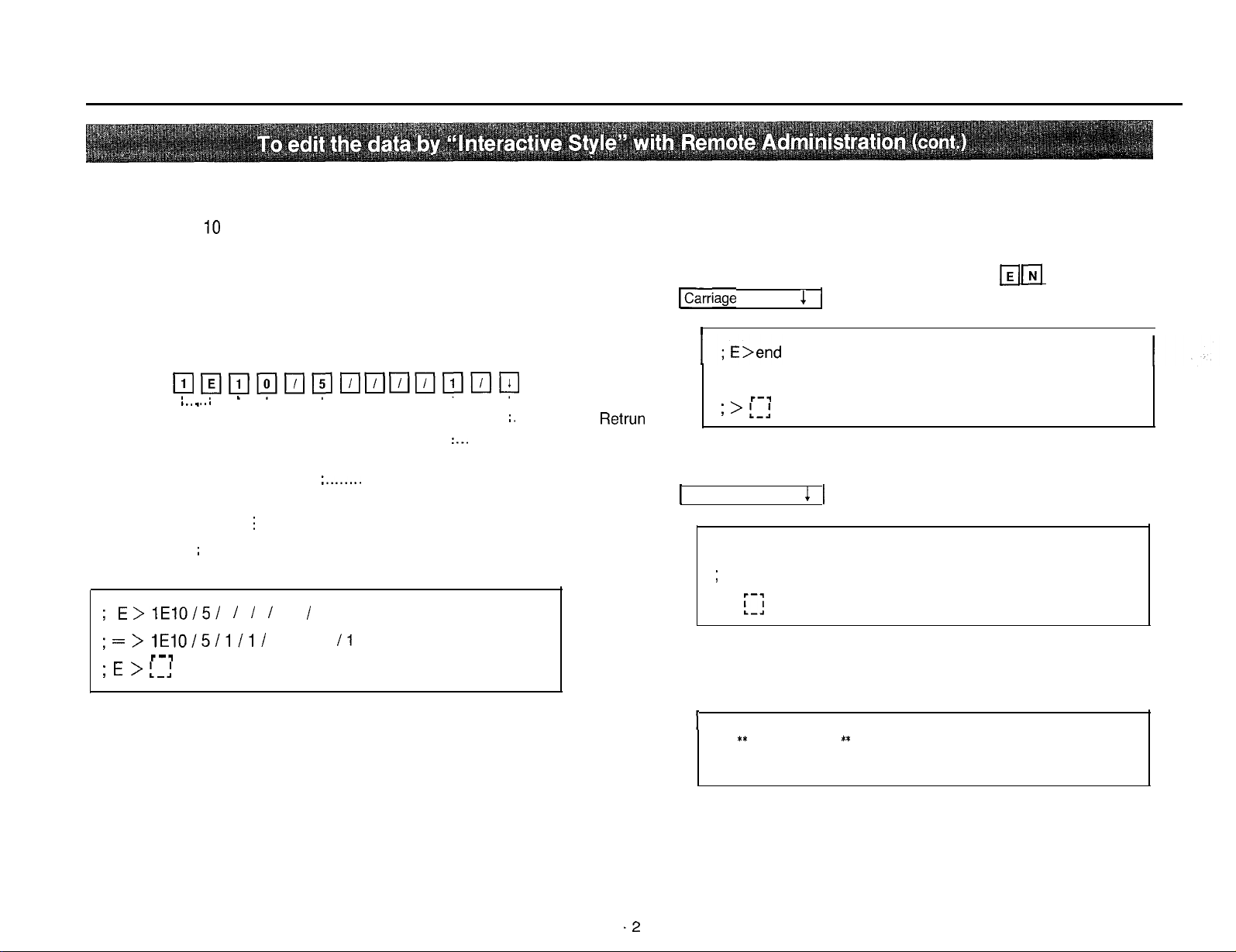
6. Change the feature corresponding to the extension connected to the
Jack number 10 as following.
Change Extension Group Assignment to group 5.
Change Account Code Input Mode to Forced.
(Refer to page 7-2)
Press the
; E>lE10/5/
;=>lE10/5/111/
; E > L-J
q
oooo@nooo~o~
I
. I .
,......
;
. . . . . . . . Main Command
r--l
. . . . . . .
i........
Parameter no. 01
(Extension Group Assignment)
i
. . . . . . . . Subcommand (Jack no.)
I I 1 1
I
I1
/o/o/o/o1
;.
. . Carriage
:...
Parameter no. 05
(Account Code Input Mode)
Retrun
7. To edit another data, repeat step 6.
8. To end the Interactive style mode, press the
ICarriage
9. To end the Edit mode, press the
1 Carriage Return ( 1 ) 1 key.
10. Press the
Return ( 1 ) 1 key.
I
Interactive style end
r-q
; > 1-1
; > end
;
Edit mode end
; >
III
q q q
q q q
command.
14 bl
and
q
and
I
,** Current time
; KX-T123211 remote administration end
.2
**
Page 27
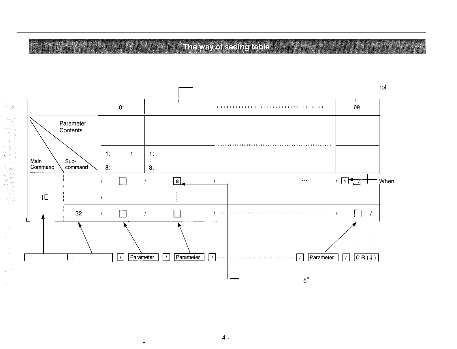
Tables are written every each command in order, so enter according to these tables.
The contents indicated with show mode are same as this format.
Parameter no. of Service Class Parameter no. of Do
Assignment of Toll Restriction
l-
I
Parameter no.
Extension
Group
Assignment
1:
Group
8:
Group
I
I
01
I
I
1E
i
;
I-
I I
I
1
8 8: Class 8
cl/
Service Class
Assignment of Toll
Restriction (Day Mode)
1:
Class
02
1
EL
. . . . . . . . . . . . . . . . . . . . . . . . . . . . . . . . . . .
. . . . . . . . . . . . . . . . . . . . . . . . . . . . . . . . . . . . . . . . . . . . . . . . . . . . . . . . . . . . . . . . . .
. . . . . . . . . . . . . . . . . . . . . . . . . . . . . . . . . . . . . . . . . . . . . . . .
.._
I &When
I
d9
Do not
Disturb
Override
0: Disable
1: Enable
-
lot
Disturb Override
How to enter
the Parameter.
1
vou enter
“Enable, enter “1”.
Main Command 1 1 Subcommand1 111 piiGz?q
111 j-Fi&zq
/TJ....
4-
-
When you enter ‘Class
8”,
enter “8”.
Page 28
E
EDIT mode
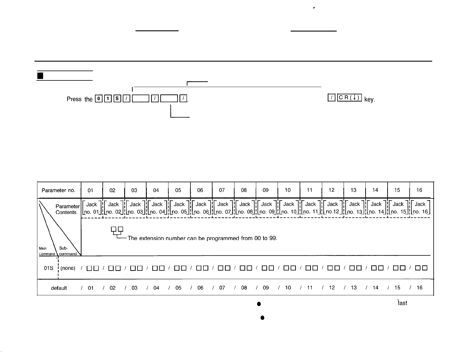
Extension Number Assignment-l (for Jack number 01 through 16)
Press the pJ~jq&fl~pj
SYSTEM FEATURE-1
,-
--------- -----------------------------
See the table below.
Jack no. 02
I
p-jIcR(I)I
key.
L
L
Main Command
Enter the extension number if you want to change it which is
assigned to jack number 01.
Need not enter the extension number if you do not want to
change it.
Note o The extension number should be programmed with
However, the practical extension number is 3 digits.
0
You can’t enter the same extension number.
5-i
last
2 digits.
Page 29
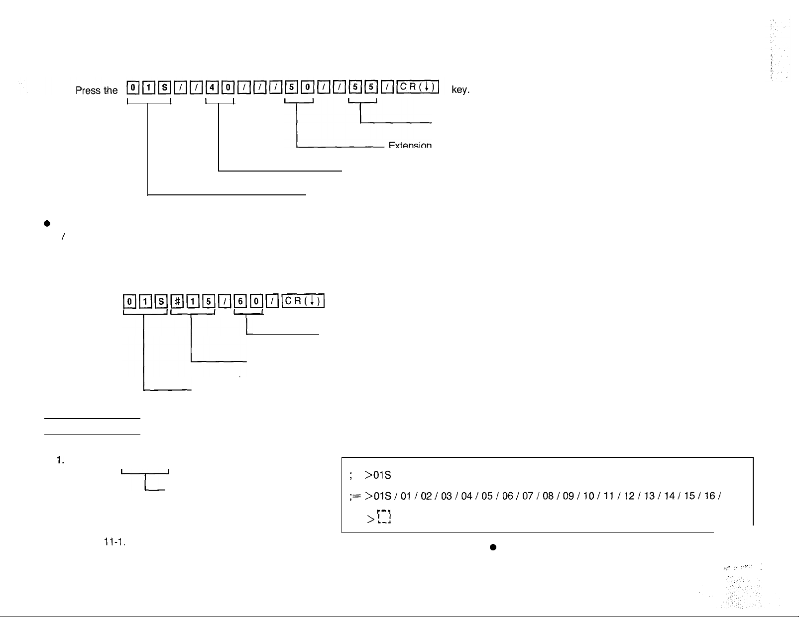
Example :
To change the extension number which is assigned to jack number 02 to 140, the extension number which is assigned to jack number 05 to 150
and the extension number which is assigned to jack number 07 to 155.
I I I I
Extension
T
Extension number which is assigned to jack number 02
Main Command
0
If the data of extension number which you want to change is one, you may use parameter number instead of pressing the boundary mark
q
’
key.
Example :
To change the extension number which is assigned to jack number 15 to 160.
Press the
•kl~~~~~~k!l~~
Parameter Number
Main Command
key.
Extension Number (last 2 digits).
Extension number which is assigned to jack number 05
number which is assigned to jack number 07
n
SHOW mode
I.
Press the q maCR(l)l key
--III
.
Main Command
Programming Table
See page
11-l.
Display (In case of default)
;
s
>OlS
;=>01S/01/02/03/04/05/06/07/08/09/10/11/12/13/14/15/16/
I.-,
; s >
1-1
Note0 The extension number on the display of Data 1
Equipment is shown with last 2 digits.
5-
‘;.~ _‘ 7.‘~‘.
:
Page 30

SYSTEM FEATURE-2
Extension Number Assignment-2 (for Jack number 17 through 32)
c
:
;‘1
n
EDIT mode
Press
Parameter no. 01
,-
I
I
the 1qqq~n~n~_---__--
II-
FL
I
L
Main Command
The extension number can be programmed from 00 to 99.
Enter the extension number if you want to change it which is
assigned to jack number 17.
Need not enter the extension number if you do not want to
change it.
Jack no. 18
See the table below.
____________
-___- ____
I
-___-__--
l~lc~(1)11
key.
02s
i(none)
IO0 IO0 ICI0 IO0 IO0 IO0 IO0 IOU ~00 IO0 ~00 IO0 IO0 IO0
I
default
n
SHOW mode
1. Press the
Programming Table
See page 11-l.
I
17 I 18
101121 bd IcR(1J1
key.
I
I
19 I 20 I 21 I 22 I 23 I 24 I 25 I 26 I 27 I 28 I 29 I 30 I 31 I 32
I
Main Command
Display (In case of default)
; s
>02s
;=>02S/17/18/19/20/21
I--,
; s >1-1
i-3
I q ICI
/22/23/24/25/26/27/28/29/30/31
Note 0 The extension number is 3 digits. The extension
number on the display of Data Terminal Equipment is
shown with last 2 digits.
0
You can’t enter the same extension number.
IO0
I321
Page 31

n
EDIT mode
SYSTEM FEATURE-3
System Speed Dialing Entry
Press the
q m~nnml
Main Command
Parameter no.
Parameter
03s
00 through 99, *
0
Automatic line access number (9)
8
Trunk group number (81 through 88)
0
Telephone number
Subcommand 00 : Speed access code 00
01 : Speed access code 01
: Speed access code 99
* :To
assign the same on all 99 Speed access codes.
01
0
Automatic line access number (9)
0
Trunk group number (81 through 88)
0
Telephone number
/
*
Up to 32 digits can be stored.
IlIllcR(s,
I
key.
0
You may program “ *
“#“, “P”, “F”
(These characters can be large or small.
The “P” button is used as Pause.
The “F” button is used as Flash.
The “S” button is used as Secret.
and
“S”
“,
button.
default
Example :
To enter the automatic line access number 9 and telephone number 123-456-7890 into speed access code 00.
*
I
Nothing stored
I
I
Automatic line access number (Trunk group number) and telephone number
Subcommand (Speed access code)
Main Command
e
5-4
Note 0 In case enter by using
all are entered as same contents
,.
“*“,
I
:.
.’
\
Page 32

I
SHOW mode
mmmmm
1.
Press the
key.
Programming Table
See pages 11-2 through
11-4.
IcR(1J1
Display (When g-123-456-7890 has been stored in the Speed access code 00.)
;s >
03soo
;
= >
03s
00 / g-123-456-7890
/
5-5
Page 33

0
Date and Time Setting
0
Operator Assignment
0
Automatic CO Hold Using DSS Button
H
EDIT mode
SYSTEM FEATURE-4
0
Day/Night Service Mode
0
Call Hunting
I
See the table on page 5-7.
L
L
Day / Night Service Mode
L
-
Automatic CO Hold Using DSS Button
I
Call Hunting - Hunting Type
Call Hunting - Setting
I
Operator Assignment
-
Time Setting
-
Date Setting
-
Main Command
Note 0 Operator 1, 2 must be entered together with Operator Assignment.
(When they are not assigned, enter
0
8 group all must be entered with Call Hunting (Setting and Hunting type).
0
Instantly
atter
pressing the Carriage Return ( 1 ) key, the new time will start.
q q q q
m.
‘5-6
Page 34

n
EDIT mode
c
(cont.)
Parameter no.
default
Note
1: Date Setting
q oElntlncl
Note
2 : Time Setting
00000
01
Date Setting
‘fear ; 00 through 99
Month ; 01 through 12
Day ; 01 through 31
Day of the week
0 : (SUN), 4 : (THU)
1 : (MON), 5 : (FRI)
2 : (TUE), 6 : (SAT)
3 : (WED),
/
8701014
02 03 04
Time Setting
Operator
Assignment
Automatic
CO Hold
Using
DSS Button
Hour ; 01 through 12
Minute ; 00 through 59
AMIPM;
;
/
O(AM)
1 PM)
12000
Jack number of
operator
I
;
01 through 32
00, 00
0 ; Without Transfer 0 ; Manual 0 ; Disable 0 ; Circular
1 ; With Transfer 1 ; Automatic 1 ; Enable 1 ; Terminate
/ 1 I
Day/Night Service Mode Call Hunting
Switching of
Service Mode
05
06 07
Setting
0
!
0000~0000! 0000~0000
Hunting Type
!
Note 3: Operator Assignment Note 4: Call Hunting
q
maocl
0
Even if you want to enter only operatorl,
“
q q
0 ‘& Q ”
”
must be entered in oprator 2.
must be entered.
00000000
group
group
group
group 5
group 4
group 3
group
group
8
7
6
2
1
q
SHOW mode
Press the
q kla
Programming Table
3ge 11-5.
5
.
m
I
-
Main Command
key
Display (In case of default)
;
s
>04s
; =
>04S /8701014/12000/00
1 ; s
>[:I
5-7
0 “
”
(underbar) is ignored with Edit mode
e&n
if it is entered or not, but it is indicated
with show mode.
0 lL
”
(underbar) can be entered anywhere.
-
,00/l / 01 OOOO~OOOO/OOOO~OOOO/
,
Page 35

0
Area Type Selection
0
CO Operator Call-Boundary Class
q
EDIT
mode
I
Press the
jqqqqnm
I I I
SYSTEM FEATURE4
0
See the table below.
1
nmnmlcRoI
-
CO Operator Call-Boundary Class
Toll Restriction of System Speed Dialing
Toll Restriction of System Speed Dialing
key.
I
SHOW mode
1. Press the
L
Parameter no.
tl
\\
05s
default
rl Fl kl 1CR(I)1
key.
I I
Parameter
Contents
I
I
i
(none)
Area Type
Selection
0: type A
1: type B
2:
!
I
Area Type Selection
type C
cl
0
Display (In case of default)
CO Operator
Call-Boundary
Class
1:
class 1
8: class 8
I
0
Toll Restriction of System
Speed Dialing
0: No Restriction
1: Restriction
0
1
I
1
’
I
Programming Table
SF-
3ge
11-5.
Main Command
” d
Page 36

n
EDIT
mode
SYSTEM FEATURE-6
Toll Restriction-Allowable Exchange Code Selection
See the table below.
*
-T-I
L’
Main Command
Parameter no.
I
I
I
06s
default
i
L
Subcommand
01 through 20, *
*
Toll Restriction-Allowable Exchange Code
01: Memory number 01
20: Memory number 20
*
: To assign the same on all 20 Memory numbers
I
IToll
/
1
Restriction-Allowable Exchange Code (3 digits)
(Enterable code are 0 through 9, *
nIxI
Nothing stored
.)
I
1
n
SHOW mode
1. Press the
~~~~~
T
Programming Table
SF
ge
11-6.
m[
T
Subcommand
Main Command
key.
Display
Memory number 01
through 20,
*
(When exchange code 212 has been stored in the Memory number 01.)
; S >
; = >
; s >
06s
01
,06SOl /
!.:I
212
/
,
Page 37

n
EDIT mode
SYSTEM FEATURE-7
0
Toll Restriction-Area Code Entry for Class 3
See the table below.
Toll Restriction-Area Code for Class 3
H
SHOW mode
Main Command
Parameter no.
I
07s
default
[
01 through 20, *
I
Subcommand
Parameter
*
000
I I
/
I
01: Memory number 01
*
: To assign the same on all 20 Memory numbers
01
LToll
Restriction-Area Code for Class 3 (3 digits)
(Enterable code are 0 through 9, >k
EICIEI
Nothing stored
.)
I
I
I.
Press the q mmaaIcR(CJTI key.
L
b-E
Main Command
Subcommand
Programming Table
SS
tge
11-6.
.._.
Memory number
01 through 20,
*
Display (When area code 123 has been stored in the Memory number 01)
; s >
;=>
5
0
07SOl
07SOl /123/
Page 38

n
EDIT mode
SYSTEM FEATURE-8
0
Toll Restriction-Exchange Code Entry for Class 5
See the table below.
*
Press the
mnnhnnmnm[
Main Command
Parameter no.
08s
Parameter
I
i
01 through
I
I
Subcommand
000
L
20,>1</
key.
Toll Restriction-Exchange Code for Class
01: Memory number 01
20: Memory number 20
*
: To assign the same on all 20 Memory numbers
01
Toll Restriction-Exchange Code for Class 5 (3 digits)
(Enterable code are 0 through 9,
on0
>I: .)
I
5
n
SHOW mode
1. Press the 14
Prolr*?mming
S .+age
11-7.
default
key.
mm m m IcR(1)I
Main Command
*
Subcommand
I
Memory number 01
through 20,
Table
Nothing stored
Display (When area code 234 has been stored in the Memory number 01)
;S >. 08SOl
*
; = >
I
,
08SOl I234 I
Page 39

SYSTEM FEATURE-9
0
Toll Restriction-Exchange Code Entry for Class 7
W EDIT
mode
-l--I
L’
Main Command
Parameter no.
09s
See the table below.
Parameter
I
i
01 through 20, *
I
L
Subcommand
Toll Restriction-Exchange Code for Class
01: Memory number 01
Memory number 20
*
: To assign the same on all 20 Memory numbers
01
q uu
LExchange
(Enterable code are 0 through
/
clclcl
Code for Class 7 (3 digits)
5
9,* .)
I
W
SHOW mode
1. Press the
Pro-*amming
‘age l-l-7.
s
/~~~~~~
Table
default
Main Command
*
key.
Subcommand
I
Memory number 01
through 20,
Nothing stored
>I:
Display
12
I
(When exchange code 345 has been stored in the Memory number 01)
Page 40

0
Hold Time Reminder
l
Hold Recall Time Set
0
Transfer Recall Time
0
Call Forwarding Starting Time
l
Pickup Dial Delay Time
SYSTEM FEATURE-101
0
CO to CO Duration Time Limit
l
Off Premise Extension (OPX)
0
Off Hook Call Announcement (OHCA)
0
Call on Hold for Standard Telephone
-
n
EDIT mode
Parameter no.
Main Command
Hold Time
Reminder
I
Hold Recall Time Set
Hold Time Reminder
Hold Recall
Time Set
See the table below.
I
Call Forwarding Starting Time
Transfer Recall Time
L
Pickup Dial Delay Time
L
CO to CO Duration Time Limit
06
Time Limit
L
Call on Hold for Standard
L
Off Hook Call Announcement
Off Premise Extension
07
Off
Premise
Extension
(OW
I
Telept
08
Announcement
default
after 1 min
after 9 min
I
0:Disable 0:2 min
1 :
30
set
2
:
1.0 min
3:1.5 min 4:4 rings delay 4:after 4
4:2.0 min 32:32 min
3
I
1
1
: 30
set
I
1
1 : 1
I
ring delay1:
3
I
I3
after1set
set
3
01:1 min
i
I
10
0 : Disable
1 : Enable
I
0
1 : Enable
I
1
2 : Hold-2
I
1
I
Page 41

1
SHOW mode
1.
Press the
Example :
0
To change “after 3 min” to “after 7 min” in Hold Time Reminder.
0
To change “3 rings delay” to “4 rings delay” in call Forwarding Starting Time.
Press the
m m kl ICR(I)I
I
111 mm 1/1m 111111 rim 111 IcR(IJ1
key.
1
I
L
Main Command
key.
Displav
(In case of default)
_.
I
I ;s > 10s
T
Programming Table
See page 11-8.
T
-
/
Main Command
L
Hold Time Reminder
Call Forwarding Starting Time
Page 42

SYSTEM FEATURE-l 1
0
SMDR Parameters
@
Incoming/Outgoing Call Selection for printing
0
Secret Speed Dial/One Touch Dial Printing
q
EDIT mode
Press the
I
mmlsll/ll11111lr;l
,-
I
nmnmnmnmm
!
k
Incoming/Outgoing Call Selection for printing
L
SMDR Parameters
L
Main Command
0
Duration Time Count Start Mode
0
External Paging Access Tone
0
DTMF Receiver Check
See the table below.
L
DTMF Receiver Check
L
External Paging Access Tone
Duration Time Count Start Mode
L
Secret Speed Dial/One Touch Dial Printing
-
key.
Parameter no.
default
01
SMDR Parameters
Page
length
04
:4
lines line
99 : 99
lines lines
A-L
I
Skip
per-fora
-tion
00
55 : 95
66,OO
t
: no
Incoming/Outgoing Secret Speed Duration Time Count
Call Selection for Dial/One Touch Start Mode
printing Dial Printing
0 : Incoming
1 : Outgoing ON
2 : Incoming ON
3 : Incoming
I
‘I
q
02
&
Outgoing OFF
Outgoing ON
&
3
”
must be entered.
I
0 : No Printing
1 : Printing
I
03
0
I
0 : Instantly
1 : 5 sec. after dial
2 : IO sec. after dial
3 : 15 sec. after dial
I 1 I
I-
IS
04
External Paging
Access Tone
0:Paging
1 :
2:Paging 2
3:Paging
Paging
05
1& 2 Disable
Enable
1
Enable
&
2 Enable
1
3
06
DTMF Receiver
Check
0 : Disable
1
: Enable
I
111
I
I
I
Page 43

q
EDIT mode
Note 0 SMDR Parameters must be entered with page length and skip perforation.
0
DTMF receiver 1 through 3 are entered at a time.
Example :
To change
To change “00” to
To change “5 sec. after dial” to “Instantly” in Duration Time Count Start Mode.
(cont.)
DTMF Receiver 3
DTMF Receiver 2
DTMF Receiver 1
“66
lines” to “77 lines” in Page Length of SMDR Parameters.
“05”
in Skip Perforation of SMDR Parameters.
Press the
I
SHOW mode
1.
Press the
~lT;1~~T;1~~~~T;1~~~lTjl[?lT;1~lT;llcRoJ
key.
-
mm m ml
I I
Programming Table
See page
11-8.
Main Command
key.
Main Command
Duration Time Count Start Mode
Display (In case of default)
;s
> 11s
;=> 11S/66,00/3/0/1
l---l
;s > 1-1
1
/3/111 I
5-l
Page 44

Direct Inward System Access (DISA)
0
Security Type
l
User Security Code
0
Remote Security Code
0
Answer Delay Time
W
EDIT mode
User Security Code 1
L
Main Command
L
Security Type
SYSTEM FEATURE-l 2
0
Prolong Time
0
Control code “
0
Tone Detect
I
I
L
User Security Code 2
See the table below.
User Security Code 3
Jc”
-
Remote Security Code
L
User Security Code 4
*
L
L
Answer Delay Time
L
Control code-“*”
Prolong Time
I
I
Tone Detect
Parameter no.
12s
default
(none) / q
;
I’
01
Security
0 : None
1 : Trunk
2 : All
I
02
I
1
0000
I
03 04 05 06
User Security Code
2 3
User Code is 4 digits
(0000 through 9999)
4
0 Remote
Security
Code
Code is 4
digits.
0000
through
9999
[
1
~uunu~nuuu~uuuu~uuuu~~nuuu~
1
I
0000
/
0000
/
0000
/
5-37
0000
/
0000
07
Answer
Delay
Time
: 0 sec.
0
1
: 5 sec.
:lO sec.
2
:15 sec.
3
0 ’ 0 1 0 1
2
/
08
Prolong
Time
0 : 2 min.
1:3
2:4
3:5
/
Control
code
0 : Disable
1 : Enable
3
/
09
“Jc”
0 : Disable
1 : Enable
cl
1
I
10
Tone
Detect
1
’
I
Page 45

Example :
To change the “Trunk” to “All” in the Security Type
To change the “0000” to “1234” in the User Security Code 2
-
I
SHOW mode
1. Press the
-
m m m ICR(I)I
key.
I I
Main Command
Main Command
;
-
Security Type
Programming Table
See page
11-l
0.
;
User Security Code 2
Display (In case of default)
;s > 12s
;=>
; s > L-1
12S/l /0000/0000/0000/0000/0000/2/3/1
I--,
/l
/
Page 46

c
.’
SYSTEM FEATURE - 13
e
Day/Night Service Mode (Starting Time)
n
EDIT mode
See the table below.
Press the
nm(SIOm’m’IOlcRoI
I
-
Subcommand
L
-
Main Command
L
0 : Sunday
1 : Monday
2 : Tuesday
3 : Wednesday
4 : Thursday
5 : Friday
6 : Saturday
* :To
assign
the same
on day of
the week
I
Starting Time of Day Service Mode
Parameter no.
I
i
13s
0 through6, * /
Starting Time of Night Service Mode
I
01
Starting Time of Day Starting Time of Night
Service Mode Service Mode
cl0
III
El
L
0 : AM
1
: PM
Minute
(00 through 59)
il
Hour
(01 through 12)
nnnnn
’
q clnnn
02
0
To set a same
mode as last,
press “0” button
instead of Hour,
Minute and AM
PM.
I
1
q
SHOW mode
1. Press the
Pror :ynming
‘eti jage 11-9.
l~~~~lCR(I)I
-lI
Table
key.
L
Subcommand (0 through
Main Command
6,>k)
default
Display (In case of default)
;
= >
5-
13Sl /
19
*
09000 / 05001
I--,
I
Example :
09000
If enter
Saturday will become the Night Mode on
Friday.
/
I
13S6 /
0 / 1 , the Day Mode on
-
05001
I
Page 47

SYSTEM FEATURE-90
IS-232C
0
Carriage Return for a New Line
0
Baud Rate
0
Word Length
I EDIT mode
Parameter no.
Communication Parameters
Press the
lqqqr;ln~~I~~n~r;ll~r;ll~T;llcRoI
7
L
Main Command
k
Parity
I
L
-
See the table below.
I
L
Carriage Return for a New Line
I
L
Word Length
03
0
Parity
0
Stop Bit Length
I
I-
Baud Rate
Stop Bit Length
04
Note
0
You can not access RS-232C communication
parameters with on-site administration
programming. (It will function with remote
administration).
90s
can be dumped with Dump mode with
remote / on-site administration.
If the dumped data are loaded with on-site
mode, “Data error” will occurs.
05
90s ;
default
I
(none)
Parity
0 : None
1 : Mark
2 : Space
3 : Even
4 : Odd
I
Carriage Return
for a New Line
0 : CR+LF 0 : 7 bits
1:CR
1
I
0
Word Length
1 : 8 bits
I
Stop Bit Length
0 : 1 bit
1
: 2 bits
0
I
0
Baud Rate
0:llOB
1
:150B
2 : 300 B
3 : 600 B
4 : 1200 B
5 : 2400 B
6 : 4800 B
7 : 9600 B
I
4
I
I
Page 48

n
SHOW mode
Display (In case of default)
1. Press the m kj m
key.
I I
Programming Table
See page
11-l
0.
ICR(I)I
Main Command
-. -
21
‘.
Page 49

OUTSIDE LINE FEATURE-l
I
CO Connection Assignment
)
Dial Mode
b
Host PBX Access Codes Assignment
1
Trunk Group Assignment
)
Automatic Designated CO Line Access
‘T
mode
See the table on page 6-2.
l
CO Mode (Normal / Direct In Line / Direct
Inward System Access) Assignment
l
Pause Time Assignment
l
Hookswitch Flash Timing
0
Calling Party Control
l
Disconnect Time
(CPC)
Signal
‘eld!llnLv
CO Mode - Day Mode
Trunk Group Assignment
Host PBX Access Codes Assignment
Dial Mode (Pulse Speed Selection)
Dial Mode (DTMF / Pulse / Call Blocking Selection)
CO Connection Assignment
L
CPC Signal
L!
Pause Time Assignment
CO Mode - Night Mode
Hookswitch Flash Timing
I
Automatic Designated
CO Line Access
Disconnect Time
Subcommand (CO number 01 through 12)
L
Main Command
Page 50

c
1 c
Parameter
i
I
\
\
default
n
SHOW mode
01
through 12.
co
Connection
Assignment
0:No
Connect
1 :Connect
/
*
01
0
02
DTMF
Pulse
Call
Blocking
Selection
0:DTMF
1 :Pulse
2:Call
Blocking
/
0
Dial Mode
Pulse
I
Speed
I
Selection
0:Low
1 :High
/
03Parameter no.
0
04 05 12
Host PBX
f
Access
Codes
Assignment
1 or 2 digits
Max codes:
8
/
llll~~~~~ll
Trunk
Group
Assignment
1 :Group 1
2:Group 2
8:Group 8
/
q
t
06 1 07
CO Mode
:DIL
Jack no. 00
through 32
must be entered
together.
Mode
Night
Mode
Mode
n
,
--L-J--
1,170
Day
Mode
0:Normal 0:1.5 set
1610 0
T
2;DISA
n
--u--
’ 1,clo
I 0 I 0 I 2 I
A
08 09
Pause
Time Flash
Assignment
1:2.5 set
2:3.5 set
3:4.5 set
,
0
Hookswitch
Timing
0:BOOmsec
1:600msec
2:900msec
3:1200msec
,
0
1
#
10
CPC
Signal
OO:Disable
01 :under 5
q6:62 msec
42;350mse(
75614msec
(See page
6-3.)
/no/
I 42 I
11
Disconnect
Time
0:1.5 set
1:4.0 set
0
0
Automatic
Designate
CO Line
Access
0:Disable
1 :Enable
/
0
/
1
Press the
Note 0 In case Host PBX Access Code are not entered, the contents are not indicated and in case an access code are set with multiple,
l In case set DIL with CO Mode, enter
0
Proaramming
$: ‘-.j~age
11-11.
,.
mmmmlcR(1)I
Main Command
key.
Subcommand (CO no. 01 through 12,
Display (In case of default)
;s >
lCO1
*)
;=>
1COl
r-7
/l/O/O/ I1
/O/O/2/1
;s > !.-1
they are punctuated with ‘I
Example : To enter 3 access codes, enter
q
“.
111 m plk1 m plr[
LIluclu
Y
CO Mode (Day/Night Mode) which is used can’t be changed
Jack number
with,lC
with remote administration.
Example : In case of remote entry from CO 01 (Day mode), CO Mode (Day mode) of CO 01 are not edited.
Table
.3
/42/O/l
I
Page 51

CPC Signal Detect Time
e
6
Page 52

n
EDIT mode
OUTSIDE LINE
FEATURE-2/s
Flexible Outward Dialing Assignment (Day/Night Mode)
Press the
Parameter no.
2C:Day Mode
3C:NiQht
Mode! 01
\
I
through 12, *
rm7-mnmnm~mnmmIcR(1)1
/
L
L
Subcommand (CO no.01 through 12,
* :To
assign the same on all 12 CO’s
I
Main Command
121 ICI
:Day Mode
131 m :Night
I
Jack
no. 01
.
/ 0000~17000
Mode
0 : Disable
1 : Enable
I
Jack no. 09 through 16
Outward Dialing Assignment (Jack no. 01 through 08)
poo-•ooql
I
Jack Jack Jack
no. 08 no. 09 no. 16
I
I I
/
q uun-•uuo
L
Jack no. 17 through 24
>k)
02
0 : Disable
1 : Enable
L-
Jack no. 25 through 32.
Note 0 Enter every 8 jacks.
0
Not necessary to enter a under bar
poo-•noql poo-•ooql
! I I I
Jack Jack
no. 17 no. 24
0 : Disable 0 : Disable
1 : Enable
/
q uuo-•uuo
“-‘I.
Jack
no. 25
1 : Enable
/
q uuu-•uuu
Jack
no. 32
default
W
SHOW mode
1. Press the
Programming Table
0
bage
b
mmmm1IICR(I)I
ll
11-12 or 11-13.
*
L
Main Command
1111 -
I
Subcommand (CO no.01 through 12,
121 ICI
131 E[ :Night
1111
key.
:Day Mode
Mode
I
1111
*)
-
1111
Display (In case of default)
; s >
; = >
; s > !-!
2COl
2COl /
I--,
I
1111
1111~1111 / 1111~1111 / 1111~1111 /
-
1111
/
1111
-
1111
,
1111~1111/
Page 53

I
EDIT mode
VU I3llJt
LINE
l-IS+
I
UHt-4/3
Flexible Ringing Assignment (Day/Night Mode)
Press the
Parameter no.
4C:Day
Mode I
SC:Night Model
nnnnIT]nmnmnmnnlcR(IJ1
-T
01 through
I
Jack no. 25 through 32.
L
Jack no. 17 through 24.
Jack no. 09 through 16.
L
Subcommand (CO no.01 through 12,
* :To
assign the same on all 12 CO’s
Main Command Note 0 Enter every 8 jacks.
17 El
:Day Mode
12, * /
14 E] :Night
[
qooo-•ooql qlooo-•nog
I I I
Jack
no. 01
0 : Disable
1 : Enable 1 : Enable 1 : Enable
0000-0000
Mode
01
L
Ringing Assignment (Jack no. 01 through 08)
*)
02
pm-•oql
I
Jack
no. 08
Jack
no. 09
0 : Disable
/ 0000~0000
Jack Jack Jack Jack Jack
no. 16
no. 17 no. 24
/ 0000-0000
0
Not necessary to enter a under bar
03
I
I I I I
0 : Disable 0 : Disable
I‘-“.
c;io00o4oo~~
no. 25 no. 32
1 : Enable
/ q 000~0000/
default
I
SHOW mode
Press the
lqmmm1IICR(I)I
LL
rogramming Table
See
3 11-14 or 11-15.
*
/
1111
L
Subcommand (CO no.01 through 12,
Main Command ; = >
m w
151 El :Night
-
1111
key. Display (In case of default)
:Day Mode
Mode
.s
I
1111
*)
6
-
1111
; s >
; s >
1111
I
4COl
4COl / 1111-1111 /
iI
-
1111
1111~1111 /
I
1111
1111~!lll /
-
1111
1111~1111
/
/
Page 54

q
OUTSIDE LINE FEATURE-G/f
Delayed Ringing Assignment (Day/Night Mode)
EDIT mode
Press the
clcl0clmn~nmnmnm~
-T
Parameter no.
6C:Day Mode I
7C:Night Model01 through
Main Command
12,*!
l-
Jack no. 25 through 32.
L
Jack no. 17 through 24.
Jack no. 09 through 16.
i
Subcommand (CO no.01 through
* :To
assign the same on all 12 CO’s
161 E[
:Day Mode
mm :Night
J&k
no. 01 no. 08
0:lmmediately 0:lmmediately 0:lmmediately 0:lmmediately
1:l
ring
2:2 rings 2:2 rings 2:2 rings 2:2 rings
3:3 rings
q El00~0000
Mode
L
Delayed Ringing Assignment (Jack no. 01 through 08)
12,*)
Note 0 Enter every 8 jacks.
0
Not necessary to enter a under bar
I
Jack
J:ck
no. 09 no. 16 no. 17 no. 24 no. 25 no. 32
I:1
ring
313
rings 3:3 rings 3:3 rings
/
q oElo-•clon
Jac; J:ck
/
0000-0000
I:1
ring
Jack
I
Jack
/
I7000~[700tl
“-‘I.
Jac;
1 :l ring
default
W
SHOW mode
Press the
Programming Table
age 11-1’6 or
s ..
/
171 m m 111 IcR(1)I
key.
11-I
*
/
Subcommand (CO no.01 through 12,
Main Command
7.
0000
161 b[
m ICI :Night
-
:Day Mode
0000
Mode
I
0000
-
0000
Display (In case of default)
*)
; S >
; = >6COl /
;s >
-6
6COl
l---l
!-!
I
0000
0000~0000 / 0000~0000 / 0000~0000 / 0000~0000
-
0000
I
0000
-
0000
,
/
Page 55

EXTENSION FEATURE-l
l
Extension Group Assignment
o
Service Class Assignment of Toll Restriction
e
Exterkion Name
l Account Code Input Mode
l
Call Transfer to Outside Line
l
Call Forwarding to Outside Line
e
Executive Override
l
Do not Disturb Override
W EDIT
mode
Press
the
l~~nnnnnnnnInInnnrn[1nnnIIn
I-
See the table on page 7-2.
I I
L-
LL
Call Transfer to Outside Line
Account Code Input Mode
Extension Name
Service Class Assignment of Toll Restriction (Night Mode)
Service Class Assignment of Toll Restriction (Day Mode)
Extension Group Assignment
Su bcommand
Call Forwarding to Outside Line
key.
Do not Disturb Override
Executive Override
L
-
Main Command
01
Jack no. 01
32 : Jack no. 32
*
: To assign the same on all 32 jack numbers
l-l
Page 56

n
EDIT mode (cont.)
Parameter no.
1E
i
01 through
default
E
SHOW mode
Press the17
01
Extension
Group
Assignment
1:Group 1
8:Group 8 8:Class 8 &Class
32,*/ 0
*
key.
Ill
mm 111 IcR(1)I
02
Service Class Assignment
of Toll Restriction
Day Mode Night Mode
1
Class
/ q /
1 1
l/i
I
Class
03
1
8
0
I
04
Extension
Name
“A” through
“a” through
“0”
through “9”
!
‘f-,;:
<>?@=”
l
‘7”
“z”
$%&‘()
Up to 10 digits
Nothing
stored
05
Account
Code Input
Mode
0:Option
1 :Forced
l
Display (In case of default)
0
06
Call Transfer
to Outside
Line
0:Disable
1 :Enable
I
0 IO I0 IO I
07
Call
Forwarding
to Outside
Line
0:Disable
1 :Enable
08
Executive
Override
0:Disable
1 :Enable
09
I
Do not
Disturb
Override
0:Disable
1 :Enable
Progr’amming
Table
See pages 11-18 or 11-19.
Subcommand (Jack no.01 through 32,
Main Command
>k)
;E
>
1EOl
;=> 1E01/1/1/1/
; E >
[:I
7-,
/0/0/0/0/0/
Page 57

Flexible CO Button
EXTENSION FEATURE-2
To Change into Other CO Button
To Change into DSS Button
To Change into Message Waiting Button
To Change into Other All CO Button
To Change into One Touch Dialing Button To Assign into Trunk Group Access Button
n
EDIT mode
-
PITS key 02
PITS key 01
-
PITS key 04
PITS key 03
-
-
PITS key 06
PITS key 05
-
PITS key 07
PITS key 08
One Touch Dial can’t be entered.
Note 0 When the Button which has been set
to One Touch Button and also One
Touch Dial has been entered is set to
One Touch Button again, the One
Touch Dial is cleared, so be careful
when you load the data
with Dump Mode.
“2E”
saved
-
-
Main Command
Subcommand (Jack no.01 through 32,
*
: To assign the same on all 32 jack numbers
.,
, -3
*)
Page 58

c
Parameter no.
A
Parameter
i
2Ei 01 through 32,
I
default
*
01
PITS key PITS key PITS key PITS key PITS key
01
02 03 04
02 03 04
9og
0 , 01
0 : CO Button CO no.01 through 12 (2 digits)
1
: DSS Button
2 : One Touch Dialing Button
3 : Message Waiting Button
*:
Other All CO Button
#: Trunk Group Access Button
*/
I 0,Ol/
0,02 / 0,03 / 0,04 / 0,05 / 0,06 / 0,07 / 0,08 / 0,09 / 0,lO / 0,ll / 0,12 /
05
05
Jack
06 07 08 09
PITS key PITS key
06 07 08
I
no.01 through 32 (2
PITS key
Note
digits)
PITS key PITS key PITS PITS
0
-Trunk Group no.1 through 8 (1 digit)
10
11
key key
09
“
q
IO
11
“must be entered together
when CO Button or DSS Button or
Trunk Group Button are entered.
12
12
H
SHOW mode
Pressthe mmIO(mm
Programming Table
See pages 11-20 or
.
Subcommand
through 32, % )
Main Command
11-22.
key. Display (In case of default)
(Jack no.01
; S >
;
= >2EOl / 0,Ol / 0,02 / 0,03 / 0,04 / 0,05 / 0,06 / 0,07 / 0,08 / 0,09 / 0,lO / 0,ll / 0,12 /
; s >
2EOl
!:I
7-7
Page 59

CO
Button, DSS Button, One Touch Button, M.W (Message Waiting) Button, Other All CO Button and Trunk Group Button can be set, but
except the key which enable to assign to the button of the unit are ignored.
Example :
When KX-T123230 is connected to Jack 02 and all PITS Buttons are set to CO Button at first and then it is changed to
Button is invalidated because CO Button is assigned to DSS button.
All the unit and the format are as follows.
Assignment
KX-T30830,
the
DSS
co1
co2
2E xx / [7 / 0 / [7 /
A A
co 1
Unable Parameter (04 through
co 2
2E
,
q . . . . . . . . . . . . . . . . . . . . . . . . . . . /
m
12) to assign to KX-T30820 and
30850.
CR(
1)
I
c] /
KX-T30850
KX-T30820
CR(
1
)
il%
co1
co2
co3
ICM
I
I2Exx /u/u
I
(DSS
11)
(DSS 18)
CO Button
1
I
/[
---I
DSS 11 DSS 18
Invalid
Enable to enter, but unable to
assign to KX-T30830.
DSS Button
I
KX-T30830
III
H3
(CO
1)
(oarameter
(parameter no. 12)
t
no.01)
t
KX-T123220
KX-T123230
KX-Tl23235
Unable parameter (07 through 12) to
assign to KX-T616 Type.
KX-T61620, KX-T61630
KX-T61650
Page 60

I
EDIT mode
DOORPHONE FEATURE -
l/2
Ringing Assignment of Doorphone (Day / Night Mode)
Press the
Parameter no.
I~nflnn~n~D~~~~
-
Main Command
rl rl
12( F\ :Night
I
I
Jack
no. 01
1
Subcommand
1 : Doorphone 1
2 : Doorphone 2
z-#:
Doorphone 1 and 2
:Day Mode
Mode
01
key.
L
Jack
Ringing Assignment of Doorphone (Jack no. 01 through 08)
I
Jack
no. 08
no.
L
rJono-•ooql
I
I
Jack
no.
09
09 through Jack no. 16
02
L
17 through Jack no. 24
I I
I I
Jack Jack Jack
no. 16 no. 17
25
through 32
Note e Enter every 8 jacks
0
gooo-000&l
I
Not necessary to enter a under bar
03
I
no. 24
rJooo-000~
B
I
I
I I
Jack
no. 25
04
“-I’.
I
1
Jack
no. 32
Command commands
.^ ^ _.
lI-‘:UayMDde
!P
: Night
default
-
I
Mode11,
:
:
2,
*
0 : Disable
1 : Enable
*
/qono~oooo
I
1111
-
1111
0:Disable
1:Enable
/qoocl,nooo
/
1111
8
-
1111
/qoon-•ocin
/
0:Disable
1:Enable
1111 1111
-
0:Disable
1:Enable
/qnclcl-•omJ/
/
1111
-
1111
/
Page 61

H
SHOW mode
Press the
Example :
fqmmIcR(1)I
L
T-
To change “Enable” for extension of jack number
Assignment of Doorphone 1 Day Mode
Main Command
key.
Subcommand (Doorphone
14 FJ
:Day Mode
121 FI :Night
Mode
Jack number 10
Jack number 09
no.1,
Display (In case of default)
2, * )
09,lO
and 15 to “Disable” in Ringing
;s >
;
= >
; s > L-1
Jack number 15
1Pl
1Pl /
r-7
1111~1111 / 1111~1111 / 1111~1111 / 1111~1111
/
Programming Table
See page 11-23.
.’
a-2
Page 62

q
EDIT mode
Paired Telephone Assignment for DSS Console
‘1’
Main Command
L
DSS CONSOLE FEATURE - 1
I-
Enter the Jack number which is paired with DSS
Console 2 (Jack no.01 through 32).
Enter the Jack number which is
paired with DSS Console 1. (Jack no.01 through 32).
q
SHOW mode
Press the
Parameter no.
I
1D
;
I
default
111 IDI IcR(IJIi
T-
Main Command
(none)
key.
01
-----------------~----------------
Enter the jack number 01 to 32.
/
I
q n ,
01
I
DSS Console 2
I
I
l Unable to enter same jack number.
o
Enter
no
02
1
I
Display (In case of default)
I
llnnnn
togerher.
,
Programming Table
>
p’
11-23.
See
Page 63

DSS CONSOLE FEATURE -
2/3
DSS Console 1 or 2-Flexible DSS Button
0
To Change into Other DSS Button
With this command, You can assign DSS Console Button to One Touch Button but One Touch Dial can’t be entered.
0
Note
If the button which has been set to One Touch Button and One Touch Dial has been entered is set to One Touch Dial Button again, One
Touch Dial will be cleared, so be careful when you load the data saved with Dump Mode.
Example : KX-T123240
DSS Buttons
Parameter no.01
Parameter no.02
Parameter no.03
Parameter no.04
0
To Change into One Touch Dialing Button
r
DSS Buttons
Parameter no.05
Parameter no.06
Parameter no.07
Parameter no.08
Subcommand 1
KX-T123240
2 3 4
Page 64

E
EDIT mode
Press the
Press the
Press the
nnnnnInr~n~n~n~n~n~n~lcR(r,
L
DSS
01
Button Button Button Button Button Button Button Button
Subcommand
Tl
•O~~~~~~~~~~~~~~~~~~r
rl
Main Command
l-qq
:
j-q-1
:
[
L
Subcommand
Main Command
p-lpj
:
p-jm :
[
DSS Console 1
DSS Console 2
DSS
09 IO
Button Button
DSS Console 1
DSS Console 2
L
DSS L DSS L DSS L DSS L DSS L DSS L DSS
02
L
DSS L DSS L DSS L DSS L DSS L DSS L DSS
03 04 05
11
Button
12 13 14 15
Button
Button Button Button
nnnnnInn~n~nInIOI010I~
L
DSS
17 18 19
Button
L
DSS i- DSS L DSS L DSS
Button Button Button Button Button Button Button
20
21
06
i-m
DSS L DSS L DSS
22 23 24
07
08
16
Button
key.
key.
key.
Press the
Subcommand
Tl
Main Command
(21M :
j-qii-j :
[
~~~~~~~~~~~~~~~~~~~~~
Subcommand
Tl
Main Command
pjp-/
:
p-pi/ :
DSS Console 1
DSS Console 2
L
DSS
25
Button
DSS Console 1
DSS Console 2
5
L
DSS L DSS L DSS L DSS L DSS L DSS L DSS
26 27 28 29 30
Button Button
Button
Button Button Button Button
31
32
key.
Page 65

Parameter
no.
-------------
-------------,-----------c-----------+-----------~-----------~-----------~-----------
-------------,-----------C-----------C-----------~-----------~-----------~
01 02 03 04 05 06 07 08
i
02 Button i 03 Button [ 04 Button I 05 Button i 06 Button I 07 Button i 08 Button
.-----------~-----------+-----------~
10 11 12 13 14
i
_---____---L-----------L----_-----------~-----------~
26
i
27
i
28
-----------,-----------~--
I
I
i
29
-----------J--
i
15 16
i
30
---------~-----------~-----------
i
31
---------~-----------
i i ; i i 23 i 2418 19 20 21 22
I
-----------~----------i
32
i i i I i
i
l ---m-------
?D
: DSS
Zonsole
2
default
Note l ‘I
!
i
I
I
I
I
I
:
I
I
I
I
q
DSS Buton assignment :
One Touch Button assignment : q
1
I
1
2
I
3
I
4
I
”
must be entered when DSS Button assignment.
1,09
1,17
1,25
,Ol
I
/
1,lO
I
1,18
I
1,26
q
I
1,02
1,03
/
/
/
1,li
1,19
1,27
iv
)
Jack no. 01 through 32
2
/
1,04
I
1,05
I
I,06
/
1,07
/
1,08
I
/
1,12
/
I,13
I
1,14
I
I,15
/
1,16
I
/
1,20
I
1,21
I
I,22
/
1,23
/
1,24
1
I
I,28
I
1,29
I
1,30
/
I,31
I
1,32
,
W
SHOW mode
Press the
Prograr ing
See
ptiyc -11-24
plmmlcR(1)(
Table
or
I-
Main Command
11-25.
‘key. Display (In case of default)
Subcommand (1 through 4, * )
p-jM
:
p-/w :
DSS Console
DSS Console 2
1
; S >
;
= >
;s > i-1
i
h. II
2Dl
2Dl /1,01/1;02/1,03/1,04/1,05/1,06/1,07/1,08/
t--q
,
. . .
Page 66

System Data Clear
0
All Parameters
0
System Parameter
l
CO Parameter (Outside)
l
To clear the All Parameters,
CLEAR FEATURE
press theFl F] Ei
JCR(I)[
key.
0
Extension Parameter
0
Doorphone Parameter
@
DSS Console Parameter
1
l To clear the System Parameter, press the
0
To clear the CO Parameter (Outside), press the
0
To clear the Extension Parameter, press the
0
To clear the Doorphone Parameter, press the
l To clear the DSS Console Parameter, press the
Note
0
CO Mode of using CO line is not cleared with Remote Administration.
0
System Feature-90 is not cleared with On-site Administration.
fl m E[ (CROI
mm /?l o(
m m m ICR(I)I
F/ ri Fl ICR(1)1
mm m ICR(I)[
key.
key.
key.
key.
key.
,,I - I
Page 67

Programing Table
Extension Number Assignment-l (for Jack number 01 through 16)
Parameter no. 01
------l-----~------L-----~-------L-----~------~-----~-----
The extension number can be programmed from 00 to 99.
default
Extension Number Assignment-2 (for Jack number 17 through 32)
Parameter no.
/
01 I 02
I I I
01; 02 ; 03 ; 04 I
------
I-----~------L-----~------,------~-----~------~-----~
!
03 I 04
The extension number can be programmed from 00 to 99.
I
05 I 06 I 07 I 08
I I
O5 ;
06 ; 07 ; 08 ; 09
I I
~------L-----~------L_____I-----~-----~------.
I
09 I 10 I 11 I 12 I
I I
;
------l------L-----J--~-----l------*-----~~~~~~~~
I
10 ;
11 ; 12 ; 13 ; 14 ; 15 ; 16
13
I 14
I I I I I
,
I
15 I 16
I
02s
jVone)
I q U
default I 17 I 18 I 19 I 20 I
I
q U
1
q U
1
q U
1
q U
1
q U
21
I 22
1
q U
1
q U
I
23 I 24 I 25 I 26
- 1
1
q U
1
q U
1
q U
I
1
q U
27 I 28 I
1
q U
I
q U
29 I 30 I
1
q U
~00
31 I 32
Page 68

Parameter no.
I
I
01
I
I
17
I
I
I
I
I
1
I
I
I
01
02
03
04
05
06
07
0
Automatic line access number (9)
0
Trunk group number (81 through 88)
0
Telephone number
(Up to 32 digits can be stored)
I
I
/
I
I
I
/
18
19
20
21
I
I
I
22
23
24
25
26
27 I
28
I
I
03s
/
I
I
I
I
I
I
I I
I
I
I
I I
I
I
I
/
I
I
I
1 I
1
I
’ I
I
03s
I
1
I
I
I
I
I
I
08
09
10
11 /
12
13
14
16
I
I
I
I
I
I
/
I
!
I
/
I
I
I
I
I
/
I
.
‘ -2
32
I
1 36
/
Page 69

38
I
I
I
I
59
I
03s
I
I
I
I
I
I
I
I
I
I
I
39
40
41
42
43
44
45
46
47
48
49
I I
I
I I
I
I I
I I
I
I
I
I
I
60
I
I
I
03s
I
I
I
I
I
I
61
62
63
64
65
66
67
68
69
70
I
I
I I
I
I
I
I
I
I
I
I
I
I
I
I
I
I
I
I
I
I
I
I
I
50
51
52
53
54
55
56
57
58
I
I
I
I
I
I
I
I
I
I
I
I
I
I
I
I I
I
I
I
I
I
I
I
I
71
72
73
74
75
76
77
78
79
I
I
I
I
I
I
I
I
I
I
Page 70

80
I I
1
03s
I
I
81
82
83
84
85
86
87
88
89
90
91
I I
I I
I I
I
I I
I
I
I
I
I
/
I
I
I
I
I
I
I
I
I
I
I
I
I
I
I
92 I
93
94
95
96
97 I
98
99
I
I
I
I
I
I I
I
I
I
I
I
I
-4
Page 71

Parameter no.
05
06 07
default
Parameter
Date Setting
Year ; 00 through 99
Month ; 01 through 12
Day ; 01 through 31
Day of the week ;
0 : (SUN), 4 : (THU)
1 : (MON), 5 : (FRI)
2 : (TUE), 6 : (SAT)
3 : (WED),
I
no.
Parameter
Time Setting
Hour ; 01 through 12
Minute ; 00 through 59
AM/PM; O(AM)
1 (PM)
8701014
/
12000
01
Area Type CO Operator
Selection
Operator
Assignment
Jack number of
operator
/
;
01 through 32
00,oo
t “
Call-Boundary
Class
Automatic
Day/Night Service Mode
CO Hold
Switching of
Service Mode
I
I
Using
DSS Button
0 ; Without Transfer
1 ; With Transfer
/
q ”
1
must be entered.
02 03
Toll Restriction of System
Speed Dialing
0 ; Manual
1 ; Automatic
0
Setting
0 ; Disable 0 ; Circular
1 : Enable
!
0000~0000
Call Hunting
Hunting Type
1 : Terminate
/
0000~0000
/
05s
default
0:
type A
1:
type
B
2:
type C class 8
8:
1
0:
No Restriction
1 :
Restriction
1:
class
I
i
(none)
I
/
I
cl
0
I
I
0
1
I
I
0
1
1
I
I-5
Page 72

Parameter no.
I
01
q uu
r
Toll Restriction-Allowable Exchange Code
(3 digits)
(Enterable code are 0 through
9,*)
Parameter no.
Restriction-Area Code for Class 3
(Enterable code are 0 through 9,
*)
06s
I
01
I
r
I
I
02
I
I
03
I
1
I
04
I
I
I
05
I
06
I
I
I
I
07
!
I
08
I
;
09
I
I
I
I
I
I
1
I
i
I
I
I
13
I
I
I
14
I
i
15
I
I
I
i
16
I
I
17
I
I
I
I
18
i
19
I
I
I
I
20
I
10
11
12
I
I
I
I
I
I
I
I
I
I
I
I
I
I
I
I
I
I
I
I
I
000
q uu
q uu
q uu
q no
q ucl
q no
nun
q ucl
q clcl
q IJU
q uu
q uu
q uu
q uu
q uu
q uu
q uu
q uu
q uu
I
I
I
I
I
I
I
07s
I
1
I
I
I
I
I
I
I
I
I
I
I
I
01
I
I
I
I
02
I
03
I
I
I
04
I
i
I
05
I
I
06
I
I
I
I
07
I
I
I
08
I
I
I
09
I
I
I
10
I
I
I
I
11
i
12
I
I
I
13
I
I
I
I
14
I
!
15
I
I
16
I
I
I
17
I
I
I
I
18
I
19
I
I
I
I
20
I
I
I
I I
I
I
I
I
I
I
I
I
I
I
I
I
I
I
I
I
I
-uuu
q uu
q uu
q uu
q uu
000
q uu
q uu
q uu
q uu
q uu
q uu
q uu
q uu
’
q uu
q uu
q uu
q uu
q uu
q uu
I
I
I
I
I
I
I
I
I
I
I
I
I
I
I
I
I
I
I
1
i
Page 73

Parameter no.
non
01
Parameter no.
08s
I
Toll Restriction-Exchange Code for Class 5
(Enterable code are 0 through 9,
(3 digits)
I
I
01
I
I
I
02
I
I
I
03
I
I
I
04
I
I
I
I
05
I
I
06
I
I
I
I
1
I
I
I
I
I
I
I
I
I
I
I
I
!
I
I
I
I
I
I
I
I
I
I
I
I
I
I
I
I
I
I
I
I
I
I
I
I
I
I
I
I
I
07
08
09
10
11
12
13
14
15
16
17
18
19
20
I
I
I
I
I
I
I
I
I
I
I
I
I
I
I
I
I
I
I
I
q nu
cl00
q uu
q nu
q uu
q nu
q nu
000
q uu
q uu
q nu
q uu
q uu
q uu
q uu
cl00
q nu
q uu
q uu
cl00
*)
I
I
I
I
I
I
I
I
09s
I
I
I
I
I
I
I
I
I
I
I
I
I
I
01
I
i
I
02
;
03
I
I
I
04
I
i
I
05
;
06
I
I
I
07
I
I
I
08
I
I
09
!
I
I
10
I
I
I
11
I
;
12
I
I
13
I
I
I
14
I
I
I
I
15
I
16
I
I
I
I
17
I
i
I
18
I
19
I
I
I
I
20
I
Toll Restriction-Exchange Code for Class 7
(Enterable code are 0 through
I
I
I
I
I
I
I
I
I
I
I
I
I
I
I
I
I
I
I
I
,
q uo
q ucl
q uu
q uu
q uu
q uu
q nu
q nu
q uu
q uu
q nu
q uu
q uu
q uu
q nu
cl00
q uu
q nu
q uu
q ucl
9,*)
I
I
I
I
I
I
I
I
I
1
I
I
I
I
I
I
I
I
I
I
I
I
I
I
I
I
I
I
I
I
I
I
:
'-7
Page 74

Parameter no.
01
02 03 04
05
06 07
08
09
I
10s i
(none)
I
default
Parameter no.
Hold Time
Reminder Time Set Recall Time Forwarding Delay Time
1 : after 1 min
9 : after 9 min 3 : 1.5 min
/
q ‘U’U’U’O
I3
SMDR Parameters Incoming/Outgoing Secret Speed
Page
length
Hold Recall Transfer Call Pickup Dial
Starting Time
0 : Disable
1
: 30
set
2 : 1 .O min
4 : 2.0 min 32 : 32 min
I
01
Skip
perfora
-tion
1
Call Selection for Dial/One Touch Start Mode
printing
0 : 2
min
1 : 30
set
I
1
02 03 04
1 : 1 ring delay1 : after 1
4
: 4 rings delay 4 : after 4
I
Dial Printing
3
I
set
set
3
Duration Time Count External Paging DTMF Receiver
co to co Off
Duration Premise Call for Standard
Time Limit Extension
(OW
01 : 1 min
;
0 : Disable
1
: Enable
‘017’ 0’
I
10
I
Access Tone
0
05
Off Hook Call on Hold
Announcement Telephone
(OHCA)
0 : Disable
1
: Enable
0’
I
1
Check
1 : Hold-l
2 : Hold-2
0’
I
1
06
I
11s i
default
I
(none) /
I
04
:4
lines lines
ii9
: 99
lines lines
nfl,
I
66,OO
A
T
00 : no
95
: 95
nn
0 : Incoming
Outgoing OFF
1 : Outgoing ON
2 : Incoming ON
3 : Incoming
Outgoing ON
/
I
/‘ Lll’
cl
must be entered.
&
&
3
0 : No Printing
1 : Printing
’
q
I
0
-I’
0
: Instantly
1
: 5 sec. after dial
2 : 10 sec. after dial
3 : 15 sec. after dial
’
q
I
,
0
: Paging 1
1 : Paging
2 : Paging
3 : Paging
’
q
1
I
&
2
Dk?able
1 Enable
2 Enable
1 & 2 Enable
3
0 : Disable
1 : Enable
’
q uo
I
111
’
I
Page 75

Parameter no.
Parameter
01
Starting Time of Day Starting Time of Night
Service Mode Service Mode
cl0
no
cl
l-
0 : AM
1 : PM
T
T
Hour
(01 through 12)
Minute
(00 through 59)
02
0
To set a same
mode as last,
press
“0”
button
instead of Hour,
Minute and AM
PM.
+
I
Example :
If enter 13S6
Day Mode on Saturday will
become the Night Mode on
Friday.
I 0 I 1 ,
the
default
>I:
I 09000 I
1
0 : Sunday 5 : Friday
1 : Monday
2 : Tuseday
3 : Wednesday
4 : Thurseday
6 : Saturday
>I:
: To assign the same
one day of the week
05001
’
-9
I
Page 76

01
02 03
04
05 06 07 08
09 10
12s i
default
(none)
Security
0 : None
1 : Trunk
2 : All
/
q
I
1
Parity
0 : None
1 : Mark
2 : Space
3 : Even
4 : Odd
I
0
User Code is 4 digits
(0000 through 9999)
User Security Code
~noon~noon~~ono~noon~onno~
01
I
0000
/
0000
02 05Parameter no.
Carriage Return
for a New Line
0:
CR+LF
1 : CR
0000
I
/
0000
Word Length Stop Bit Length
0:7 bits
1:8 bits
Remote
Security Delay
Code Time
0
Remote
Code is 4
digits.
0000
through
9999
[
1
Answer
0
1
2
3
I
0000
0:1
1:2 bits
bit
/
2
Prolong Control
Time
: 0
sec.
: 5 sec.
:10 sec.
:15 sec.
0 /
0 : 2 min.
1:3
2:4
3:5
q
/
3
Baud Rate
0 : 110 B
1
:15OB
2 : 300 B
3 : 600 B
4 : 1200 B
5 : 2400 B
6 : 4800 B
7
: 9600 B
Tone
code “
0 : Disable 0 : Disable
/
q
I
1
’
jc”
1 : Enable 1 : Enable
Detect
/
q
I
1
/
I
90s [
default
(none)
/
I
q
1
’
I
n
u
0
1
q
I
0
,
.n
1 cl
I
0
1 u
I
-
4
I
I
Page 77

06
Parameter no. 08
1 07
I
I
I
I
I
I
I
1c
i
I
I
I
I
I
:
I
I
I
I
I
I
I
I
I
I
I
I
t
I
I
I
I
I
I
I
I
I
I
I
I
I
--
lefault
co
Connection
Assignment
D:No
Connect
1 :Connect
04
'U/U
Dial Mode
ITMF I
Use
I
Zall
3locking
Selection
):DTMF
I :Pulse
?:Call
Blocking
%lse
Speed
Selection
3:Low
1 :High
/u/
05 I 0 I 0 I q
06
07.'
08
'u/u
q
lo
I
q ! q
'u/u
lo!
09 I q I q I q
10 I
11 I q /
12 I q I q / q
*
*
0
‘U/UlUf
I
I
1
0
I
cf
I
/
0
0
cf I
/
0
Host PBX
Access
Codes
Assignment
1 or 2
digits
Max codes:
8
I
/
/
I
!
/
/
Nothing
stored
Trunk
Group
Assignment
1 :Group 1
2:Group 2
8:Group 8
I
q
! 0
I
q
I
q
I 0
I q
I
q
I
q
I q
I q
^^
1
:c;v,
l;:co;
&COLT-
’
’
’
’
’
’
’
/
Pause
Time
Assignmen
1:2.5 set
2:3.5 set
3~4.5 set
’
’
CO Mode
Day
Mode
0:Normal 0:1.5 set
1610 0
T
-
2;DlSA
Mode
n n
‘0
---mm_
’ 1,uu
cl
--mm--
’ 1,uu
0
--m-m-
’ 1,uu
0
--v-m-
’ 1,uu
cl
---mm- --____
’ 1,uu
cl
----mm
’ 1,uu
0
----
’ -1,u
III 17
---m-w
’
1,170
0
--s-m-
’ 1.00
0
-----w
’ 1,017
Night
Mode
.
:DIL
Mode
Jack no. 00
through 32
must be entered
q
0
---___
’
1,uu
0
----__
’
1,uu
0
--____
’
1,uu
0
---___
’
1,uu
0
’
1,uu
0
-----
’ -l,uu
1 -;&- /
,
-----
’ -l,uu
0
El
-----_
’
1.00
‘0
-----
’ -1,uu
'
0
q
q
q
q
q
q
q
q
q
q
2
Hookswitch
Flash
Timing
0:SOOmsec
1:600msec
2:900msec
3:1200msec
I
q
I
q
I
q
I
q
I
q
I
q
/
q
I
q
I 0
I
q
I
1
Signal Time
OO:Disable 0:1.5 set
01 :under 5 1:4.0 set
06:62 msec
07:70 msec
42:350msec
75:614msec
/
q
/UU’
/UU’
/mu/
/UU’
I‘ cm
/
q
/UU’
/uu/
‘UU’
/
U’ q
q
q
q
q
I q I q
u/ q
q
q
q
42
'
Automatic
Designated
CO Line
Access
D:Disable
1 :Enable
I q ,
/
q /
‘0,
/ 17,
‘0,
/ 0 /
/
q ,
‘17,
I
q /
0
1
I
I
Page 78

Flexible Outward Dialing Assignment (Day Mode)
Parameter no.
?C:Day
Mode
.
Parameter
I
I
I
I
I
I
I
I
I
I
I
I
I
I
I
I
I
I
I
I
I
i
I
I
I
I
I
I
I
I
I
I
I
I
I
I
I
I
I
I
I
I
I
I
I
I
I
I
I
I
01
02
03
04
05
06
07
08
09
10
11
12
*
01
qono-•ooyl
I
I
I I
Jack
no. 01
0 : Disable 0 : Disable
1 : Enable 1 : Enable
/
q uuu-•uou
I
Jac;
no. 08
pooo~ooo&l
I
I
Jack Jack Jack
no. 09 no. 16
/ 0000-0000 /
/ 0000~0000 / cluuu-•uuu / 0000~17000
/ 0000~00017
/ q
uuu~uuuu
/
0000~0000
/
q uuu.-•uuu
/ 17000~0000
/ q
uuu~uuuu
/ q uucl~nuou / q uuu~uuciu / 0000~0000 /
/
q uuu-•uuu
/
q uuu-.uuuu
/ q
uuu~cluuu
/ 0000-0000
/
q uuu.-•uuu
/ 0000~0000 / 0000-0000
/ 0000~0000 / 0000-0000
/
q uuu-•uuu
/
q uuu-•uuu
/
q uuu-•uuu
/
q uuu-•uuu
/
q uuu-•uuu
/
q uuu-•uuu
02 03
I I I
I I I I
I
gooo~oouc;r
I
no. 17
0 : Disable 0 : Disable
1 : Enable 1 : Enable
q nou-•unn
/ 0000~00170
/
q uuu-•uuu
/ q uuu~uuuu / q ouu~uoou /
/
q uuu-•uuu
/ 0000~01700
/
q uuu-•uuu
/
q uuu-•uuu
/ q
uuu~uuuu
/ 0000-0000 /‘UUUU-•cluu /
/ 0000~01700
I
Jack Jack
no. 24
no. 2.5
/ cllJcln~nclnlIl/
/ q 000~0000/
/ q 000~0000/
/ q nuu~uuuu /
/
q uuuJIHIluu/
/ q uuu~uuuu/
/ q uuu~unuu/
/
q uuuAIHIluu/
/ q cluu~uclclu
/ q uuu~uuuu/
goon-ooo~
I
I
04
Jac;
no. 32
I
I
/
default
*
I
1111
_
1111
1111
/
_
1111
,
,2
/
1111
_
1111
/
1111
_
1111
/
Page 79

Flexible Outward Dialing Assignment (Night Mode)
Parameter no.
Parameter
01
02
QOOO-•OOQ QOOO-•OOQ
I I
I
1
Jack
no. 01
I
Jack
no. 08
I
I
I
Jack
no. 09
Jack
no. 16
03 04
QEIULIIUUQ
I I
I I I I
I
Jack Jack Jack
no. 17 no. 24 no. 25 no. 32
I
Jac;
QOOO-•OOQ
I
I
I
I
default
*
I
1111
_
1111
/
1111
_
1111
/
1111
_
1111
/
1111
1111
_
/
Page 80

Flexible Ringing Assignment (Day Mode)
Parameter no.
4C:Day Mode
-
. .
I
I
I
r
I
I
I
I
I
I
I
I
I
I
I
I
I
I
F-
I
I
I
I
I
I
I
I
I
I
I
I
I
I
I
f
I
I
I
I
I
L
I
I
I
I
I
I
I
01
02
03
04
05
06
07
08
09
10
11
12
*
01 02 03 04
QunoxlooQ
I I
I I
I
Jack
no. 01
0 : Disable 0 : Disable 0 : Disable 0 : Disable
1 : Enable
Jack
no. 08
/ 0000~0000 / q uuu~cluuu /
/
q
uuu-•uuu
/
q uuu-•uuu
/
q uuu-•uuu
/
q uuu-•uuu
/ q
uuu~uuuu
/ q
uuu~uuuu
/
q uuu-•uuu
/
q uun-•uuu
QUUU-oonp
I
I
I I I
Jack
no. 09
1 : Enable 1 : Enable
/
q uun-•ouo
/
q uuu-•uuu
/
0000~0000
/
q uuu-•uuu
/ q
uuu~uuuu
I
I
Jac;
no. 16
/ 0000~0000 / 0000~0000 /
/
q uuu-•uuu
/
q uuu-•uuu
QUOO~OOOQ
I
I
Jack
no. 17 no. 24
q
uon-•unu
I I
I I I
Jack
/ 0000-0000 / q 000~0cl00/
/
q uuu-•uuu
/
q uuu-•uuu
/
q uuu-•uuu
/
tluuu-•auu
/ q uuu~unuu/
/
q uuuJIKKlu/
/ q
q uuuAIluuu/
/
q uuu-•uuu
/
q uuu-•uuu
/ q
/ q 000~0[700/
QOOOIlOOQ
I
Jack
no. 25
1 : Enable
/
q uunAxlun/
Jack
no. 32
uuu~uuuu/
/ q tlutl~unuu/
uuu~uuuu/
/ q uuu~uuuu / 0000~0000 / 0000~0000 / q uuu~uuuu/
/ q
uuu~uuuu
/ 0000~0000 / q
/ 0000~0000 /
/
q uuu-•uuu
uuu~uuuu
q uuu-•uuu
/
q uuu-•uuu
/
q nuu-•uuu ; q
/ 0000~0000 /
/ q uuu~uuuu/
000~00[70/
q uuu-•nuu/
default
*
I
1111
1111
_
/
1111
_
1111
1111
/
_
1111
/
1111
1111
_
/
Page 81

Flexible Ringing Assignment (Night Mode)
Parameter no.
Parameter
~000-000~
I
I
I
Jack
no. 01
01
Jac;
no. 08
02
p-•ooAmoyl
I
I
I
I
I
I
I
I
~000~000&l
I
I
I
Jack Jack Jack Jack
no. 09
no. 16 no. 17 no. 24
03 04
lqooo-•oop
I I
I I
I
Jack Jack
no. 25
no. 32
I
I
I
default
*
I
1111
_
1111
/
1111
_
- I.5
1111
/
1111
_
1111
/
1111
_
1111
/
Page 82

Delayed Ringing Assignment (Day Mode)
Parameter no.
X:Day
Mode
Parameter
I
I
I
I
I
I
I
I
I
I
I
I
I
I
I
I
I
I
I
I
I
I
;
I
I
I
I
I
I
I
I
I
I
I
I
I
I
I
I
I
I
I
I
I
I
I
!
I
I
01
02
03
04
05
06
07
08
09
10
11
12
*
01
QUUU-•UUQ
I I
A
no. 01
0:lmmediately
1:i
ring
2:2 rings 2:2 rings 2:2 rings 2:2 rings
3:3 rings
/
q UUU-•UUU /
/
q UUU-•UUU /
/
q UUU-•UUU / q UUU-•UUU / q UUU-•UUU / q UUUAIloUU/
/
q
UUU~UUUU
/
q UUU-•UUU /
/
q UUU-•UUU / q UUU-•UUU / q UUU-•UUU / q UUU-•UUU/
/
q UUU-•UUU /
/
q UUU--•UUU /
/
q UUU-•UUU /
/
q UUU-•UUU /
/
q UUU-•UUU / q
/ UUUU-UUUU
/
q UUU-•UUU /
JacL
no. 08 no. 09 no. 16 no. 17 no. 24
/
QUUU-•UUQ QUUU-•UUQ
I I
J&k
0000-0000
0000-0000
/ q UUU-•UUU / q UUU-•UUU / q UUU-•UUU
0000~0000
0000-0000
0000-17000
0000-0000
0000-00017
UUU-0000
UUUU-UUUU
0000-0000
02
I I
Jaci
0:lmmediately
1:l
ring
3:3 rings 3:3 rings
J&k
0:lmmediately 0:lmmediately
1:l
ring
/ q UUU-•UUU / q UUU-•UUU/
/ q UUU-•UUU / q UUU.IlUUU/
/ q UUU-•UUU / q UUU-•UUU/
/ q UUU-•UUU / q UUU-•UUU/
/
0000-0000
/
q
/
q
/
q UUU-•UUU / q UUU-•UUU/
UUU-noun
UUU~UUUU
/ q UUU-•UUU /’ q UUUAIlcllJU/
/ q UUU-•UUU / q UUU-UUnU/
03 04
QUUU-•UUQ
I
JacL
Jick
no. 2.5
1:l
ring
3:3 rings
/ q UUU-•UUU/
/ q UUU-•UUO/
/ q lJUU-•UclU/
I
Jack
no. 32
/
default
*
I
0000
0000
_
/
0000
_
0000
/
0000
_
0000
/
0000
0000
_
/
Page 83

Delayed Ringing Assignment (Night Mode)
Parameter no.
7C:Night Mode
Parameter
I
I
I
I
I
I
I
I
I
I
I
I
I
I
I
I
I
I
I
I
I
I
/
I
I
I
I
I
I
I
I
I
I
I
I
I
I
I
I
I
I
I
I
I
I
I
I
I
01
02
03
04
05
06
07
08
09
10
11
12
*
01
~onoAmoq
JLlck JacL
no. 01
0:lmmediately 0:lmmediately 0:lmmediately 0:lmmediately
1:l
ring
2:2 rings
3:3 rings
/
q uuu-•uuu
/
0000~0000
/
q uuu-•uuu
/
q uuu-•unu
,
I
no. 08
goon-•uug
J;ck
no. 09
/
q uuu-•uuu
/ q uuu~uuucl /
/ q uuu~uuuu /
/
q uuu-•uuu
/ 0000~0000 / q uuu~uuuu /
/
q uuu-•uuu
/
q uuu-•uuu
/ 0000~0000 / q uuu~uuuu /
/ q
uuo~uuclu
/
q uuu-•uuu
/ 0000~0000 /
/ 0000~0000
/ 0000~0000
/ 0000~0000
/
q uuu-•uuo
/
q uuu-•uuu
q uuu-•uuu
/ 0000~0000
/
q uuu-•uuu
/
q uuu-•uuu
02 03 04
I
Jack
no. 16 no. 17 no. 24 no. 25 no. 32
1 :l ring
2:2 rings 2:2 rings 2:2 rings
313
rings
/
q uuu-•uuu
q
uuu-•uuu
q uuu-•uuu
/
q uuu-•uuu
q
uuu-•uuu
/
q
uuu-•uuu
q uuu-•uuu
/
q
/
q
uuu.-•uuu
/
q
nuu-•uuu
/ 0000-01700
/ 0000~0000
/ .uuuu~uuuu
quuu-•uuq
I I I I
J&k
1 :I
ring
3:3 rings
JacL
lJouu~uouq
Jick Jaci
1:l
ring
313
rings
/ q uuu~uuuu /
/
q uuu-•ouu/
/
q uuu-•ouu
/
0000~0000
/
q uuu-•uuu/
/ q uuu~ulJuu/
/
q nuu-•uuu
uuu-tluuu / q
tlnu~tlouu
/ q uuu~uc7uu/
/ q uuu~ucluu/
/ q uclu~ucluu
‘/ 0000~0000
/ 0000~0000
/
/
/
/
/
/
/
default
>I:
I
0000
_
0000
/
0000
!
‘-1-I -
_
0000
17
/
0000
_
0000
/
0000
0000
_
/
Page 84

Parameter no.
06
07
08 09
Extension
\
ParameterParameter
Group
Assignment
Service Class Assignment
of Toll Restriction
Day Mode Night Mode
1:Group 1
&Group
I
I
I
01
I
I
I
I
02
I
I
I
I
03
I
I
I
I
I
04
I
I
I
I
05
i
dIl'u~0'
~u~n~o~
dIl~u~0~
~0~udIl~
~Clfcl~U~
8
1
Class
AClass
1
1:Class 1
8
8:Class 8
Extension
Name
“A” through
“a” through
“0”
through “9”
!
*+-.;:
<>?a=-
l
“7
“2
$%a’0
Up to 10 digits
Account
Code Input
Mode
Call Transfer
to Outside
Line
Call
Forwarding
to Outside
Line
0:Option
1 :Forced
0:Disable
1 :Enable
0:Disable 0:Disable
1 :Enable
'0'0'0~[7~[7'
~cl~0dIl~0dzl'
dIl~0dIl~0dIl’
‘cl/ q ldIl~
dIl’0dIl~0dIl’
q dIl’
Executive Do not
Override Disturb
+
Override
0:Disable
1 :Enable
1 :Enable
1E
-,
i
06
I
I
I
I
07
I
I
I
08
I
I
I
I
I
09
I
I
I
I
10
I
I
I
I
:
I
I
I
!
I
11
I
I
I
I
I
I
12
13
14
~0fudrlJ
dIl~UJU~
dIl~udzl~
dIl~udIl~
dIl~UdIl~
dIl~u~u~
dIl~UdIl~
uxl~udIl~
~u~u~u~
'u'uuxl~u~u'
'0'0'0~0dIl'
‘U’U’U~U~U
dJ’LldIl~0dIl’
oIliouIl~0dIl~
uzl~0dIl~0~17~
‘0~0dIl~17dIl’
io~uoIl~udIl'
/
q
/
q ! q
/LO /n /
-
,4’-40
Page 85

1E
I
I
15
I
I
I
I
16
I
I
I
17
I
I
I
18
I
I’
I
19
I
1
I
I
I
20
I
I
I
21
I
I
I
22
I
j
I
23
I
I
I
24
I
I
I
I
25
I
‘U’LI’U’
‘0’0’0’
‘0J0’0’
‘0’0’0’
‘U’U’U’
‘U’U’U
‘U’U’U
'U'U'U
’
q ’ q
'U'U'U
'Cl'U'Uf
’
q ,’
‘n’n’n’lIl’u’
‘u’u’u’u’uJ
‘0’0’0’0’0
‘0’0’0’0’0
‘u’o’n’n’o’
‘n’u’u’u’u’
‘U’U’U’U
'u'u'u'u'u'
‘u’u’u’u’u’
'ufu'u'u'u'
‘0’
q ‘U’ q ‘U’
q I
I
I
I
26
I
I
I
I
27
I
i
I
28
I
I
I
I
I
29
I
I
I
I
30
I
i
I
31
I
I
I
I
I
32
I
I
I
I
defau
If
-_
._
*
*
‘U’U’CI’
‘U’U’U
'U'U'U
‘U’U’U
'UJCI'U'
‘CI’U’U’
'U'U'U
‘UJCI’U
I
1
- -..
1 1
I
Nothing
stored
‘.
.
.._
I - 1 9
‘u’u’u’u’u’
‘u’u’u’u’u’
‘cl’
‘0’0’0’0’0’
J
q ’ q ’
‘El’
q ‘UJ q ‘U’
q ‘U’
'u'u'u'u'u'
‘u’u’u’u’u’
I
0
I
0
I
III*’
0
q
I
0
I
.b
I
IO
I
I
Page 86

Flexible CO Button
Parameter no.
I
I
;
(KX-T )
I
I
I
i
(KX-T )
I
I
I
; (KX-T
.2E
I‘
I
I
!
(KX-T )
I
I
I
:
(KX-T )
01
PITS key PITS key PITS key PITS key PITS key PITS key PITS key PITS key PITS key PITS key
(CO 01)
01
02
03
)
’
04
05
02
(CO 02) (CO 03)
$lLlLfl
0 : CO Button
1 : DSS Button
2 : One Touch Dialing Button
3 : Message Waiting Button
*
: Other All CO Button
if:
Trunk Group Access Button -Trunk Group no.1 through 8 (1 digit)
03 04
(CO 04) (CO 05) (CO 06) (CO 07)
05
CO no.01 through 12 (2 digits)
Jack no.01 through 32 (2 digits)
06
07
~
_-----_
08
(CO 08) (CO 09) (CO 10) (CO 11)
0 C‘ f7.J ”
09 10
must be entered together
when CO Button, DSS Button or
Trunk Group Button are entered.
11
PITS
key PITS key
12
(CO 12)
I
09
I
(KX-T )
4
Please write the unit connected to each extension.
1
I -
/
:-;
213
Page 87

2E(‘
I
I
10
! (KX-T )
;
I
11
I
, (KX-T ) ,
I
I
I
12
;
(KX-T )
I
I
I
I
13
_------
_------
; (KX-T )
I
I
!
(KX-T )
’
14
i
I
15
I
(KX-T )
I
I
I
I
I
_------
__----_
_-----_ _-----_
I
.
I
19
I
I (KX-T )
I
I
I
22
1
fKX-T I
I
I
23
I fKX-T j
I
I
24
i
(KX-T
)
_------
I ‘, -
21
Page 88

I
I
26
f
(KX-T )
I
I
27
I
I (KX-T
I
I
I
I
:
(KX-T )
I
I
I
)
28
29
! (Kx-T 1
i
I
I
30
!
(KX-T )
I
I
I
I
31
i
(KX-T )
I
I
I
32
!
(KX-T )
I
I
-mm----
I
default
*
I 0,Ol/
0,02 / 0,03 I 0,04 ' 0,05 I 0,06 I 0,07 I 0,08 / 0,09 / 0,lO / 0,ll
' 0,12 I
1. 22
Page 89

Ringing Assignment of Doorphone (Day / Night Mode)
Parameter no.
Parameter
I
I
I
I
lP:Day
Mode I
2P : Night
Mode
default (1 P / 2P)
i
I
I
I
I
I
I
I
I
i
;
01
gooo-•ooc;l
I I
I I
I
Jack
no. 01
0 : Disable
1 : Enable
/
1
2
*
1
2
*
*
q uuu-•uun
/ cluucl-cluun
/
q unu-•uuu
/
q uuu-•uuu
/
q uuu-•uucl
/
q nun-0000
I
1111
-
I
Jack
no. 08 no. 09
1111
LJnoo-mu&l
I
I
I
Jack Jack
/ q uclcl~uuucl
/ 0000-0000 / cluuu~uuuu / q 000~(7000/
/ q 000~0[700
/ q
uuu~cluuu
/ 0000-0000
/ 0000-0000
/
1111
02
gooo-•00Ql gooo-•noc;l
I
I
no. 16
0 : Disable 0 : Disable
1 : Enable 1 : Enable
I
I
I
Jack
no. 17 no. 24
03 04
/ q uuu~uuuu /
/ q uuu~clnutl /
/
q
uclu-0000
/ q
uuu~uuuu
/
q uuu-•uuu
-
1111
/
1111
-
Jack
1111
I
I I
I
I
Jack
no. 25 no. 32
0 : Disable .
1 : Enable
Jac;
I
q uuu-•uun/
q nnu-•oun/
/
q mlclAIlonu/
/ q uuu~uunu/
/ q uuu~uouu/
/
1111
-
1111
/
Paired Telephone Assignment for DSS Console
Parameter no.
1D
default
Parameter
I
i
(none)
I
DSS Console 1
-----------------~----------------0
The Jack number can be paired
from 01 to 32.
0 ‘6 r;l”
/
I
must be entered.
on
01
01
:
DSS Console 2
;
I
’
on
02
I
Page 90

DSS Console l-Flexible DSS Button
Parameter no.
\ \
D : DSS
Console
default
1
I
I
I
I
;
1
I
I
I
I
I
I
I
I
I
I
I
i
I
I
I
I
I
I
I
I
I
I
I
;
I
I
I
I
I
I
I
01
1 3 1 ..J?~~---~~~~2L-
i
DSS
One Touch Button assignment :
2
-----------L-----------L--------------~-----------~-
l-l l-l
III
-----__
,
-.
, , , , , ,
02
---- :--‘-“-
26
Buton
assignment :
q
------
-.;
;
27
, , , , , q , , , , , ,
_--------_
-
,
3
4
*
1
2
3
4
o:i-ii-i
___-------
, 17 ,, ,, , ,
--_------- --------_
, q ,
I
I
I
I I
q
0 0 0
n
1,Ol
1,09
1,17
1,25
,
;,
, ,
/
/ 1,lO
I
l-l
o,-y-i-i
oli-ii-i
r
o;BEi-i
1,02
1,18
1,26 1,27
,
-&-pi
---------
, b ,, ,, , ,
1
,
--,
/
/
I
/
03
-------
~~~~0 ” q ” must be entered.
:2!
l-l l-l l-l l-i
0 0
r-l
l-l
;,
, ,
1,03
I,11
1,19
------- pl-------i--2n
;
28
-.Ii-iimi
,
o1s-ii-i
/
/
/
I
n
ojEi-i
n
U
0
o-s-ii-i
1,04
1,12
1,20
1,28
I
I
29
,
,
,
/
/
/
I
05
----------~-----------~-----------~-----------.
)
Jack no. 01 through 32
cl
, O:S-iimi , o:s-ii-i , o:s-ii-i ,
n
oj2imi
n
U
OTS-iisi
cl
OTS-ii-T
1,05
1,13
1,21
1,29
I
I
06
---- ---j-_23
30
I
i
31
0
,
,
,
1
/
/
I
l-l l-l
oIjzi-i
-
U
o,s-ii-i
0 c
o-s-ii-i
1,06
1,14
1,22
1,30
, o7 ;, , ,
,
o:s-ii-i
,
o:ijimi
/ ’
/
I
/
07 08
_______
n
q
----__
L-
7
1,07
1,15
1,23
1,31
pfz _______.
I
32
l-l
0
...;i-ii-i,
l-l
o:-~iBi,
,
,
/
/
I
/
cl
oSi-?l-i,
l-l
oIl”;-iBi,
1,08
1,16
1,24
1,32
/
/
I
/
Page 91

DSS Console 2-Flexible DSS Button
Parameter no.
:D:
DSS
Console 2
;
I
I
I
I
I
I
I
I
’
I
I
I
I
I
I
I
-----------
-----------‘-----------
-----------p-m---------+--+-----
________-_-L-----------L-----------L-----------~-----------~-----------~-----------~-----------
1
, ,
O:i-iT-i
,
2
3
a
o-i-
,
o-i-
01
!
L-----------L-----------+--------------~
I
r r----
I
I
!
DSS
One Touch Button
0
0
---- ------
, , , ,
cl
---- ------ ------ -----
, , , ,
0 0
02 03
02 Button
10
18
26
Buton
assignment :
0 0
O,i-ii-i
q
-~-
, , , , ,
0
-~-
, , , , ,
i i
I 03 Button
I
11
I
-------
;
19
!
27
assignment :
, , , ----- ,
------+-----------t-----------1--------------
q
O,i-ii-J
0 0
-------
-.
, , , , , ,
cl
-.;
, , , , ,
cl
!
04 Button I 05 Button I 06 Button I 07 Button i 08 Button
I
I
T
;
i
. Jack no.
04
12
------_____
20 1 21
28
2
...:S-ii-T
o,7
cl
oli
q
05
i
-----------~-----------~-----------~-----------
!
13
t-----------t-----------~-----------~-----------
I
29
0
o;i
----_ ----- -----
, , , ,
, , , ,
0
,, ,
El
oIi-ii-i
0
O-S-ii-i
I
;
I
,
El
06
14
22
30
0 I‘
q
01 through 32
o:S-ii-T
,
o-5
”
must be entered.
q
q
O,r
cl
----_
, , , ,
0 0 0
07
i
I
I
15
;
23
~-----------~-----------
I
31
, ,
, , , ,
El
o:i-ii-i
0
o,5
0 0
o-s-ii-i
I
;
24
!
32
, , , ,
,
08
16
0
o,i-7i-i,
q
O:i-ii-i
o,i-ii-i
default
I
I
1
I
I
i
I
I
2
i
I
I
3
.I
I
I
I
4
I
1,Ol
I I,09
I,17
I I I I I
I,25
/
1,02
/
1,lO
/
1,18
1,26 1,27 1,28 1,29
/
1,03
/
1,ll
I
1,19
/
/
/
Ii - 7.5
1,04
1,12
1,20
I
1,05
/
1,13
/
1,21
/
1,06
/
1,14
/
1,22
/ / /
I,30
/
I,07
/
I,15
/
I,23 I
1,31 1,32
/
1,08
/
1,16
1,24
I
I
I
I
Page 92

Supplement
On-site / remote administration has 5 modes excluding an unsetting
mode and prompt shows the current mode.
(prompt)
; > . .
;
E>
;
s>
;
P>
;
; D> .
0
0
Edit / Show mode must be entered after the disposal style is set. The
Style are Interactive style (“ITT” command) and Batch style
command) and These styles are done only with Edit / Show mode.
0
0
0
0
0
..
‘.
.’
R>
“END” is used to remove a command.
“; >”
is indicated just after on-site / remote administration.
Carriage Return ( 1 ) key is used to execute a command.
Enable to enter large or small alphabet character.
Message or prompt corresponding to the command are indicated
with right enterance.
“Command error” is indicated with incorrect enterance.
The digt of a command are three digits.
(Setting mode command)
unsetting mode
Edit mode
Show mode
Dump mode . . . . . .
System Working Report mode
Diagnostic mode . . . . . . . .
Mode / Style Exit . . . . .
. . . . . . . . . . . .
. . . . . . . . . .
. . .
. .
. .
. . .
. . .
.
EDT
SHW
DMP
RPT
DIG
END
Mode Style
-
remove command
(“FIL”
There is “HLP” command to help which modes must be entered
next and this command can be entered with every mode.
Example ;If enter the “HLP” command after the starting
message of administration, the following message are
indicated.
;
Welcome to KX-Tl23211
; **Jan. 1. 1988
; Tfe “HLP” displays command informations
;
Select the
.
.
.
&-
:;
-------------------------------------~
; > 1-1
. . . . . . . . . . . . . . . . . . . .
Edit
Show
. . . . . . . . . . . . . . . . . . . .
Dumc,
. . . . . . . . . . . . . . . . . . .
Workingreport
-----
Diagnostic
r-q
t
12:00’AM**
mode
-_-------------------------
...........*.
. . . . . . . . . . . . . . .
remote administration
ver 2.0 Panasonic CO., LTD
Press
the “HLP”
EDT (cr)
SHW (cr)
DMP (cr)
RPT
DIG
(cg
(cr)
~
I
If Diagnostic Card is not installed, this item will not appear.
Page 93

To edit/show, you must enter the command to edit/show after each
mode are set.
The commands are as follows.
System
-I
Outside Line
Extension
01s.. .
lC...7C
lE,
2E
13s,
90s
Disposal Execute Command consists of Main Command,
Subcommand and Parameter.
Example;
03s 99
L
A
Enter Speed Dialing to Speed Code 99 with Edit
Interactive Mode.
Punctuation between Command and
Parameter
The end of parameter
r
/
9-l 23-456-7890
F
I
1
DSS Console
-I
-i
0
Main Command consists of numeral and alphabet. The alphabet
means as follows.
S - System E - Extension D - DSS Console
c - co P - Doorphone
0
The above commands consists of parameter (except
0
Enable edit mode to edit the setting contents by repairing
parameter.
Enable show mode
Example;
to,show
command
Operator @I Automatic CO Hold using DSS
@
Day/Night service mode @ Call
can edit/show them.
lD...3D
Doorphone
lP,
2P
Clear
99A, 99S, 99C, 99E, 99P, 99D
parameter.
04s
consist of 0 Date 0 Time
Hunting,and
99A-99D).
@
Buttom
Lpar
I
w
To edit the data at a time with Main Command which has
Subcommand, press “ t ” key.
If enter
al-2
T
06s t /123/ 1
are entered.
06SOl /
r
LO6S201 123/
.
123 / 1
, it comes to same
1
amet er
Subcommand (Speed
access code)
Main Command
thing.as
3
below all data
Page 94

When enter Disposal Execute Command, the ways are done as
follows.
Main Command = M
Subcommand = S
Param:eter 1
Parameter n = Pn are explained as this.
Alphabet of Main Command can be entered with large and small
q
character.
The punctuation of Command and Parameter is done with
n
q
The maximum character number enable to enter with one
Command are 78 digits and if exceed the number it’ll come to be
Data error.
n
Comment Sentence
If the first line is started with “ ;
as Comment Sentence.
n
Underbar “ -”
does not affect an operation.
is indicated to let you show a data easily and it
=
Pl
Lines after that will be regarded
“,
Supplement
“/“.
(cont.)
E
The entering ways are different by the case that there is a
Subcommand, there is no Subcommand and edit or show at a
time.
0
Edit Mode (Subcommand):
0
Edit at a time: M t
@Edit Mode (No Subcommand): M I Pi I P2 I. . . I Pn I 1
@Show Mode (Subcommand):
0
Show at a time:
@Show Mode (No Subcommand):
H
Default of Parameter (Edit Mode)
To set the default of Parameter, press “ A ” key.
Example;
Also, In case All parameter with Command is set as default
MS * 1 (To default all parameter with Subcommand S of Main
Command)
Example;
M * A 1 (To default all parameter with all Subcommand of Main
Command)
Example;
M A 1(To default all parameter with Main Command M)
Example;
Jack number 01 is set to Extension setting
Command “01 S” as default value.
OlSl Al
To default the Starting Time of Day/Night Service
Mode on Monday, press
To default the Starting Time of Day/Night Service
Mode on Sunday through Saturday, press
13s *
To default the Parity, Carriage Return for a New
Line, Word Length, Stop Bit Length and Baud
Rate, press
1
Al.
90s
h
MS/P1 /P2/.
MS1
M*l
M
1 .
/Pl /P2/. ./Pn/l
1
13Sl A
1.
.
./Pn/l
lr-3
n Sequence Enter of parameter (Edit Mode)
The order of entering parameter is decided by Main
and you must obey the entering format.
Cornmar+
Page 95

W
Omission of Parameter (Edit Mode)
In case there are parameter which need not to change, enter only
‘I/”
to the location of parameter.
Example;
4
Edit with parameter number Assignment
When you want to edit one parameter only, enable to edit the
parameter by assigning the parameter number.
Example;
n
Execute Command
To execute command, press the Carriage Return key ( 1).
Only terminal no. 3 is set to Extension number
setting Command
OlS///A/l
LJack
L
Jack
L
Jack number 01
If you want to edit only Toll Restriction of System
Speed Dialing 03 into No Restriction
Resetriction
Command
05s$$o3 /
of System Speed Dialing setting
05s.
0 / 1
01s
as default value.
number 03
number 02
“0”
with Toll
n If you enter the wrong data while entering the data, the display on
data terminal will show the following.
I;[
When batch style
n When communication prameter stored into KX-T123211 is different
from them stored into Data terminal equipment.
;
Communication error
..............s.....
If there is a wrong entrance when execute command by pressing
Carriage Return (1) key, new data are not entered.
,,’
:i
.
 Loading...