

Page 1
INSTALLATION MANUAL
ELECTRONIC MODULAR SWITCHING SYSTEM
KX-T123210
EASA-PHONE
Panasonic
Please read this manual before connecting the KX-T123210
Page 2
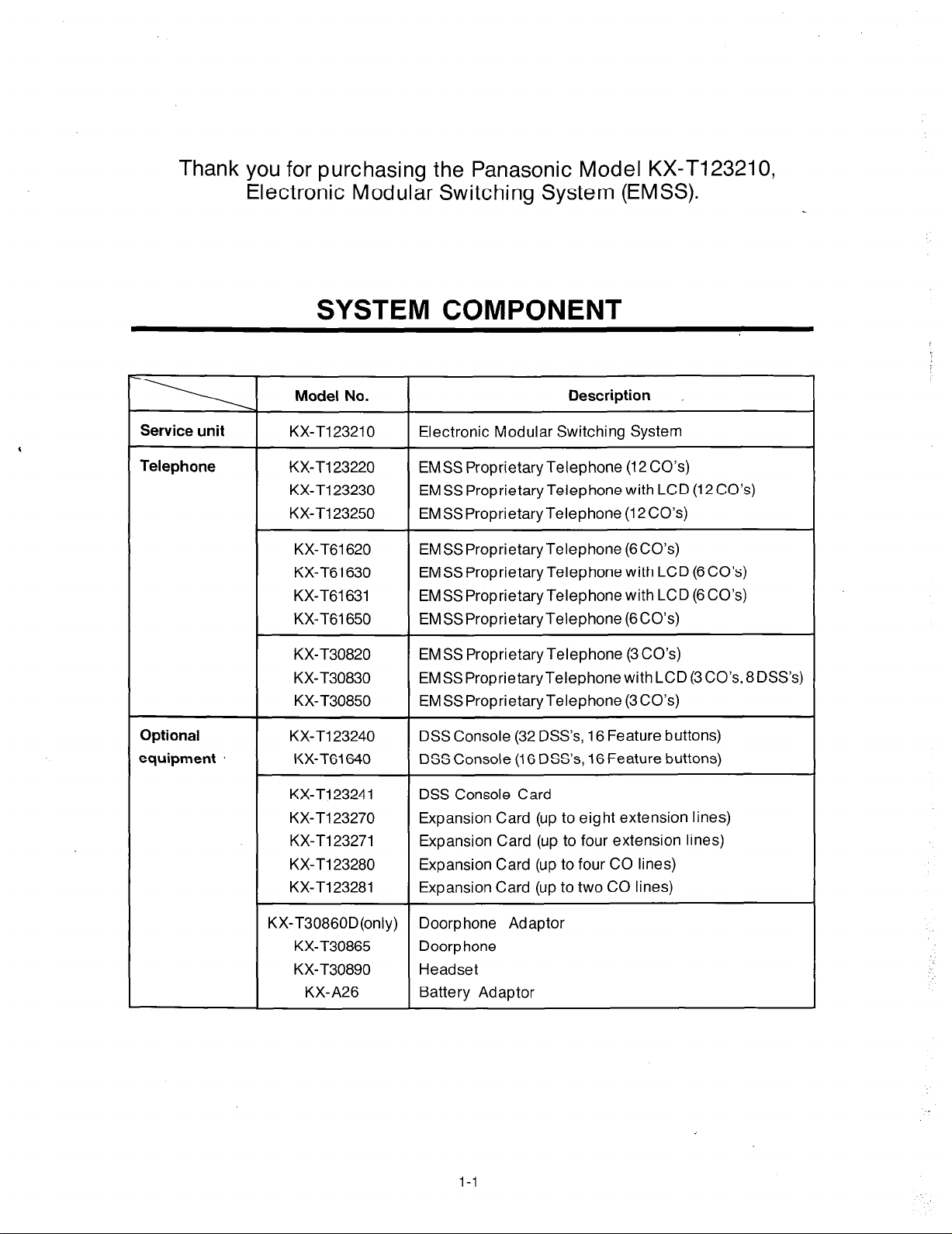
Thank you for purchasing the Panasonic Model KX-T123210,
Electronic Modular Switching System (EMSS).
SYSTEM COMPONENT
Service unit
Telephone
Optional
equipment
Model No.
KX-Tl23210 Electronic Modular Switching System
KX-T123220 EMSS Proprietary Telephone (12CO’s)
KX-Tl23230 EMSSProprietaryTelephonewithLCD(12CO’s)
KX-Tl23250 EMSSProprietaryTelephone (12CO’s)
KX-T61620 EMSSProprietaryTelephone (6CO’s)
KX-T61630 EMSSProprietary Telephone with LCD (6CO’s)
KX-T61631 EMSS Proprietary Telephone with LCD (6 CO’s)
KX-T61650 EMSSProprietaryTelephone (6CO’s)
KX-T30820
KX-T30830
KX-T30850 EMSSProprietaryTelephone (3CO’s)
KX-Tl23240 DSS Console (32 DSS’s, 16 Feature buttons)
KX-T61640 DSS Console (16 DSS’s, 16 Feature buttons)
KX-T123241 DSS Console Card
KX-Tl23270 Expansion Card (up to eight extension lines)
KX-T123271 Expansion Card (up to four extension lines)
KX-T123280 Expansion Card (up to four CO lines)
KX-T123281 Expansion Card (up to two CO lines)
EMSS ProprietaryTelephone (3CO’s)
EMSSProprietaryTelephonewithLCD(3CO’s,8DSS’s)
Description
KX-T30860D(only) Doorphone Adaptor
KX-T30865 Doorp hone
KX-T30890 Headset
KX-A26
Battery Adaptor
1-l
Page 3
NOTIFY THE TELEPHONE COMPANY
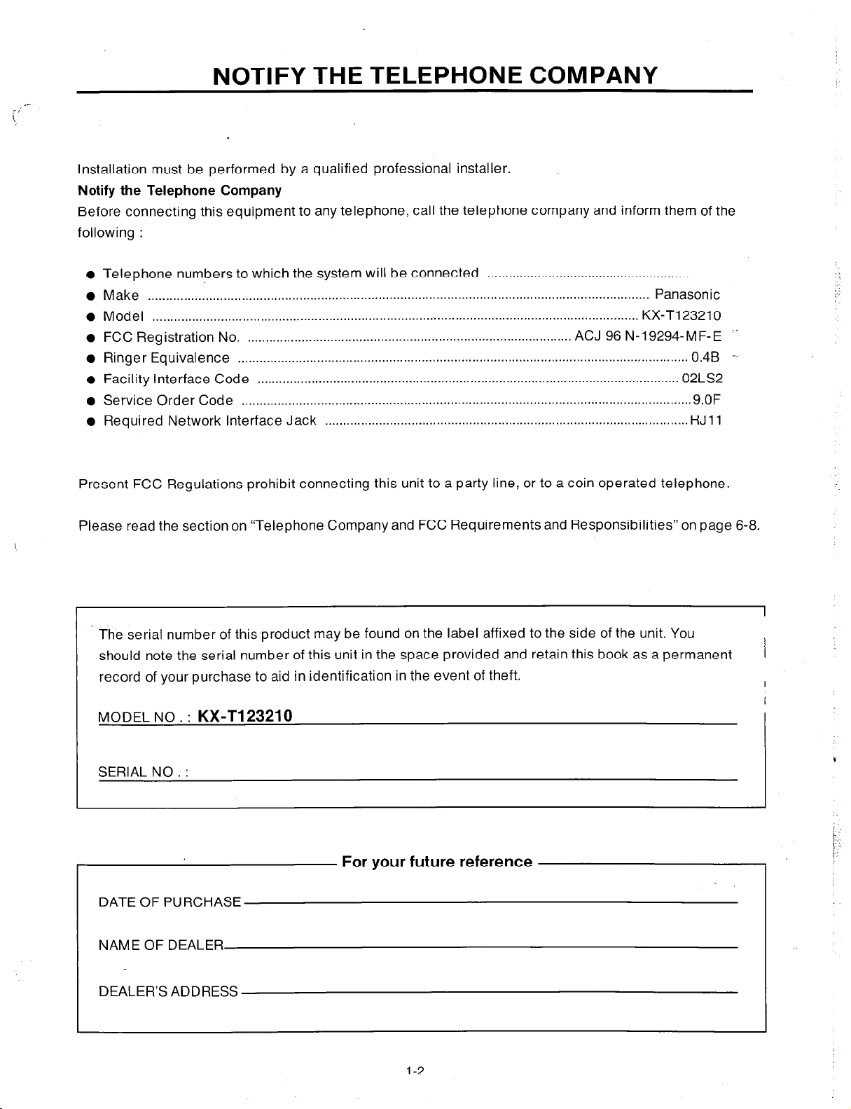
Installation must be performed by a qualified professional installer.
Notify the Telephone Company
Before connecting this equipment to any telephone, call the telephone company and inform them of the
following :
Telephone numbers to which the system will be connected ........................................................
Make ............................................................................................................................................ Panasonic
Model ........................................................................................................................................ KX-T123210
Ringer Equivalence -- ............................................................................................................................. 0.4B
Facility Interface Code ..................................................................................................................... 02LS2
Service Order Code ............................................................................................................................. 9.OF
Required Network Interface Jack ..................................................................................................... RJ 11
Present FCC Regulations prohibit connecting this unit to a party line, or to a coin operated telephone.
-’ FCC Registration No. .......................................................................................... ACJ 96 N-19294-M F- E
Please read the section on “Telephone Company and FCC Requirements and Responsibilities” on page 6-8.
The serial number of this-product may be found on the label affixed to the side of the unit. You
should note the serial number of this unit in the space provided and retain this book as a permanent
record of your purchase to aid in identification in the event of theft.
MODEL NO . :
SERIAL NO. :
KX-Tl23210
For your future reference
DATE OF PURCHASE
L
1
I
NAME OF DEALER
DEALER’S ADDRESS
l-2
Page 4
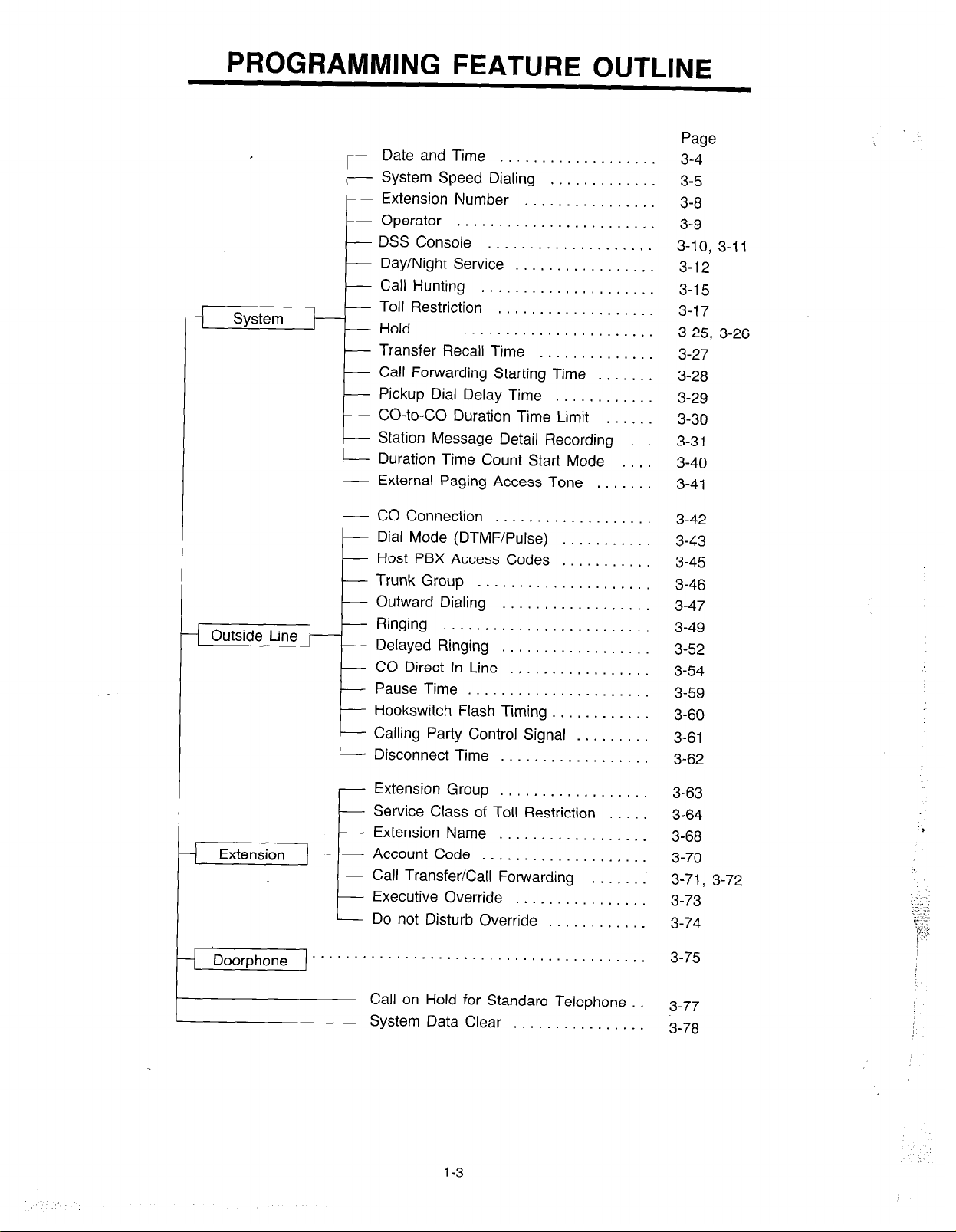
PROGRAMMING FEATURE OUTLINE
Date and Time . . . . . . . . . , . . . .
System Speed Dialing . . . . . . . .
Extension Number
Operator . . . . . . . . . . . . . . . . . .
DSS Console . . . . . . . . . . . . . . . .
E-
Day/Night Service
Call Hunting
k
System
---E
Toll Restriction
Hold ...........................
Transfer Recall Time
Call Forwarding Starting Time
Pickup Dial Delay Time
CO-to-CO Duration Time Limit
Station Message Detail Recording
Duration Time Count Start Mode
E
I
External Paging Access Tone
CO Connection
Dial Mode (DTMF/Pulse)
Host PBX Access Codes
Trunk Group
Outward Dialing
Ringing
Delayed Ringing
CO Direct In Line
Pause Time ......................
Hookswitch Flash Timing
Calling Party Control Signal
t
Disconnect Time
. . . . . . . . . .
.................
.....................
...................
...................
.....................
..................
.........................
..................
.................
..................
..............
............
...........
...........
............
.........
.......
......
.......
....
...
Page
3-4
3-5
3-8
3-9
3-10, 3-11
3-l 2
3-l 5
3-l 7
3-25, 3-26
3-27
3-28
3-29
3-30
3-31
3-40
3-41
3-42
3-43
3-45
3-46
3-47
3-49
3-52
3-54
3-59
3-60
3-61
3-62
.
Extension Group
Service Class of Toll Restriction
Extension Name . . . . . . . .
Extension
---E
) Doorphone ” ” ” ’
Account Code . . . . . . . .
Call Transfer/Call Forwarding
Executive Override . . . . .
t
Do not Disturb Override . .
. . . . . . . . . . . . . . . . . . . . . . . . .
Call on Hold for Standard Telephone .
System Data Clear . . . . . . . . . . . .
1-3
..................
........
........
.......
........
........
........
.....
3-63
3-64
3-68
3-70
3-71, 3-72
3-73
3-74
3-75
3-77
3-78
,
Page 5
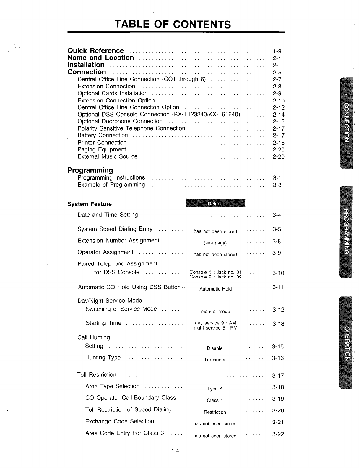
TABLE OF CONTENTS
Quick Reference
Name and Location’:::::::::::::::::::::::::::::::::::
Installation
Connection ‘:::::::::::::::::::::::::::::::::::::::::::
Central Office Line Connection (CO1 through 6) .............
Extension Connection ..................................
Optional Cards Installation ...............................
Extension Connection Option ............................
Central Office Line Connection Option .....................
Optional DSS Console Connection (KX-T123240/KX-T61640) .
Optional Doorphone Connection ..........................
Polarity Sensitive Telephone Connection ...................
Battery Connection ................
Printer Connection ................ ....................
Paging Equipment ................ ....................
External Music Source ............. ....................
Programming
Programming Instructions ..........
Example of Programming .......... . . . . . . . . . . . . . . . . . . . .
System Feature
Date and Time Setting ............. . . . . . . . . . . . . . . . . . . .
. .
. .
. .
.
. .
.
. .
l-9
2-l
2-l
2-5
2-7
2-8
2-9
2-l 0
2-l 2
2-l 4
.
2-l 5
2-l 7
2-l 7
2-l 8
2-20
2-20
.
3-l
3-3
3-4
System Speed Dialing Entry ........
Extension Number Assignment ......
Operator Assignment ..............
Paired Telephone Assignment
for DSS Console ............
Automatic CO Hold Using DSS Button ...
Day/Night Service Mode
Switching of Service Mode .......
Starting Time ..................
Call Hunting
Setting .......................
Hunting Type. ..................
Toll Restriction ....................
Area Type Selection ............
CO Operator Call-Boundary Class. ..
Toll Restriction of Speed Dialing .
Exchange Code Selection .......
Area Code Entry For Class 3 ....
has not been stored
(see page)
has not been stored
Console 1 : Jack no. 01
Console 2 : Jack no. 02
Automatic Hold
manual mode
day service 9 : AM
night service 5 : PM
Disable
Terminate
.
. . . . . . . . . . . . . . . . . . . . . . .
Type A
Class 1
Restriction
has not been stored
has not been stored
. . . .
. . . . .
. . . . .
’ ’
’ . . . .
3-5
3-8
3-9
3-l 0
3-l 1
3-l 2
3-13
3-l 5
3-l 6
3-l 7
3-l 8
3-19
3-20
3-21
3-22
1-4
Page 6
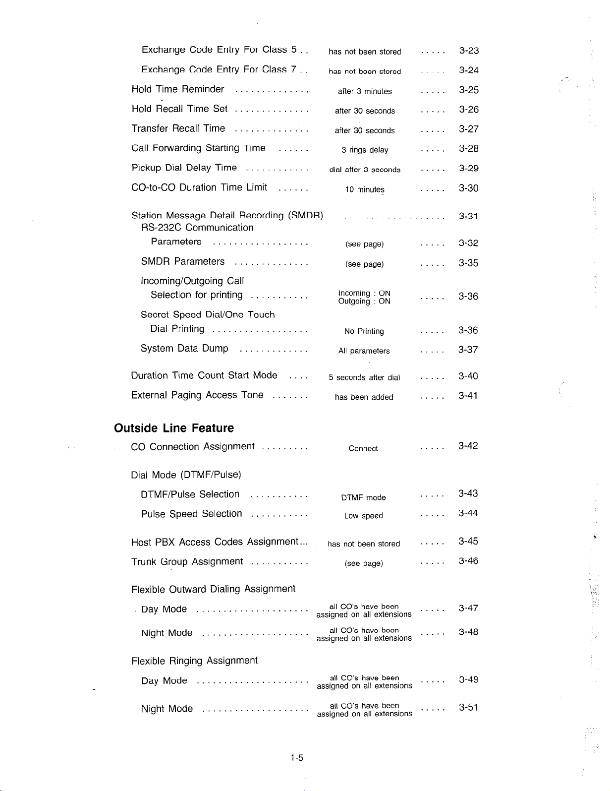
Exchange Code Entry For Class 5
has not been stored
. . .
3-23
Exchange Code Entry For Class 7 .
Hold Time Reminder
Hold Recall Time Set
Transfer Recall Time
Call Forwarding Starting Time
Pickup Dial Delay Time
CO-to-CO Duration Time Limit
. . . . . . . . .
..............
..............
......
............
......
Station Message Detail Recording (SMDR)
RS-232C Communication
Parameters . . . . . . . .
SMDR Parameters . . . .
. . . .
. .
Incoming/Outgoing Call
Selection for printing . .
.
Secret Speed Dial/One Touch
Dial Printing . . . . . .
System Data Dump . . .
.
. .
has not been stored
after 3 minutes
after 30 seconds
after 30 seconds
3 rings delay
dial after 3 seconds
10 minutes
. . . . . . . . .
(see page)
(see page)
Incoming : ON
Outgoing : ON
No Printing
All parameters
. . . .
.
.
. . . .
. .
. . .
. . . .
. . .
. . .
. . .
. . .
. . .
. . . .
3-24
3-25
3-26
3-27
3-28
3-29
3-30
3-31
3-32
3-35
3-36
3-36
3-37
Duration Time Count Start Mode
External Paging Access Tone . . . . . .
Outside Line Feature
CO Connection Assignment . . . . . .
Dial Mode (DTMF/PuIse)
DTMF/Pulse Selection
Pulse Speed Selection
Host PBX Access Codes
Trunk Group Assignment
Flexible Outward Dialing Assignment
Day Mode
. . . . . . . . . . . . . . . . . . . . .
Night Mode . . . . . . . . .
Flexible Ringing Assignment
Day Mode
. . . . . . . . . . . . . . . . . . . . .
Assignment..
.
5 seconds after dial
has been added
DTMF mode
Low speed
has not been stored
(see page)
all CO’s have been
assigned on all extensions
all CO’s have been
assigned on all extensions
all CO’s have been
assigned on all extensions
Connect
. . .
. . .
. . .
. . .
. . .
. . . .
. . .
. .
. . . .
. . . . .
3-40
3-41
3-42
3-43
3-44
3-45
3-46
3-47
3-48
3-49
\ : . .
!
i
:’ :
Night Mode
. . . . . . .
1-5
all CO’s have been
assigned on all extensions
. . .
3-51
Page 7
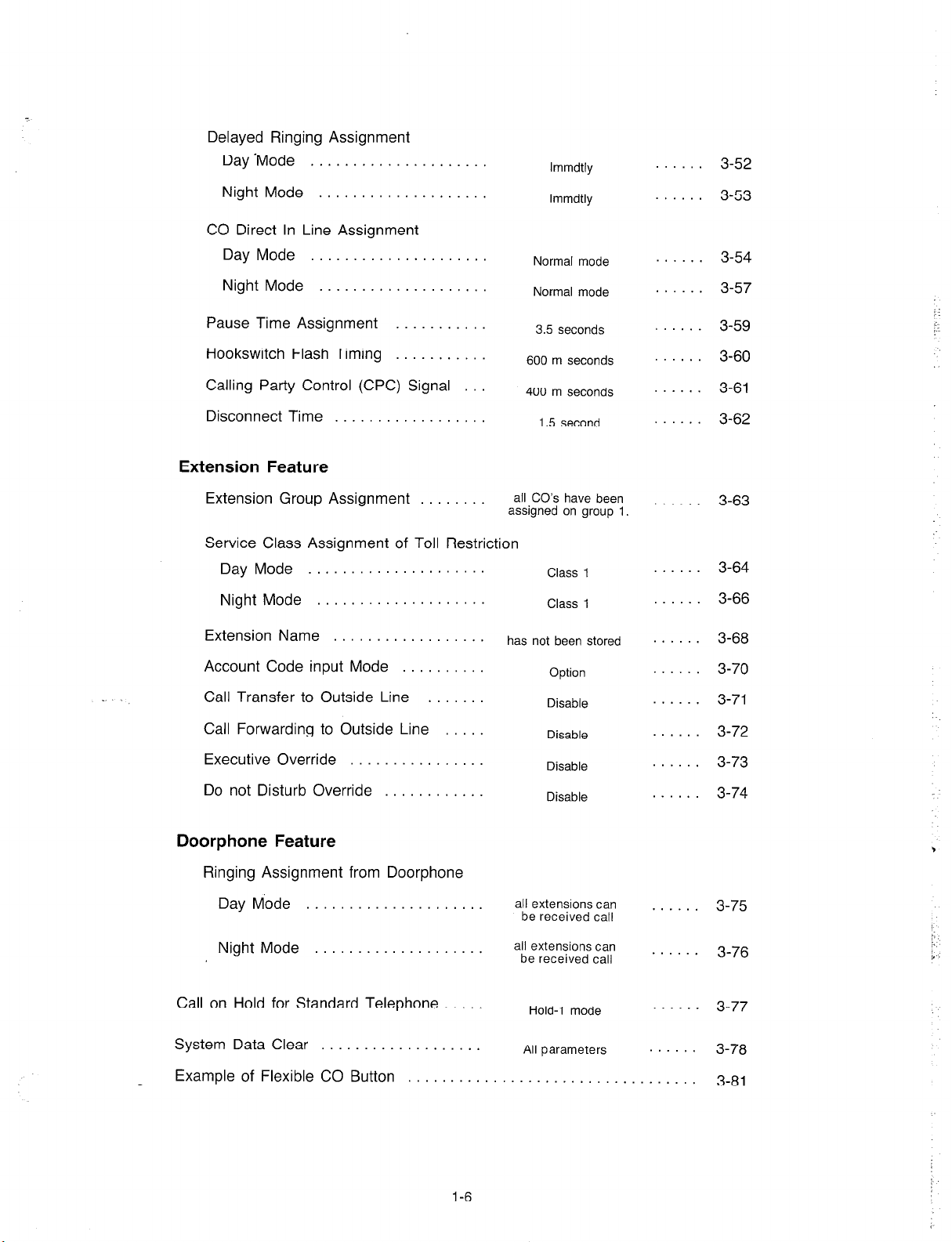
Delayed Ringing Assignment
Day ‘Mode . . . . . . . . . . . . . . .
Night Mode . . . . .
CO Direct In Line Assignment
Day Mode . . . . . . . . . . . . . . . . . . . . .
Night Mode . . . . . . . . . .
lmmdtly
lmmdtly
Normal mode
Normal mode
......
......
......
......
3-52
3-53
3-54
3-57
Pause Time Assignment . .
Hookswitch Flash Timing . . . . .
Calling Party Control (CPC) Signal .
Disconnect Time . .
Extension Feature
Extension Group Assignment . . .
Service Class Assignment of Toll Restriction
Day Mode . . . . . . . . . . . . . . . . . . . . .
Night Mode . . . .
Extension Name . . . . . . . . .
Account Code input Mode . . . . .
Call Transfer to Outside Line . .
Call Forwarding to Outside Line .
Executive Override . . .
Do not Disturb Override . . . . . .
3.5 seconds
600 m seconds
400 m seconds
1.5 second
all CO’s have been
assigned on group
Class 1
Class 1
has not been stored
Option
Disable
Disable
Disable
Disable
1
......
......
......
......
. . . .
......
......
......
......
......
......
......
......
3-59
3-60
3-61
3-62
3-63
3-64
3-66
3-68
3-70
3-71
3-72
3-73
3-74
Doorphone Feature
Ringing Assignment from Doorphone
Day Mode . . . . . . . . . . . . . . . . . . . . .
Night Mode . . . .
Call on Hold for Standard Telephone . . . . .
System Data Clear . . . . . . . .
Example of Flexible CO Button . . . . . . . . . . . . . . . . . . . . . . . . .
1-6
all extensions can
be received call
all extensions can
be received call
Hold-l mode
All parameters
......
......
......
.....
3-75
3-76
3-77
3-78
3-81
Page 8
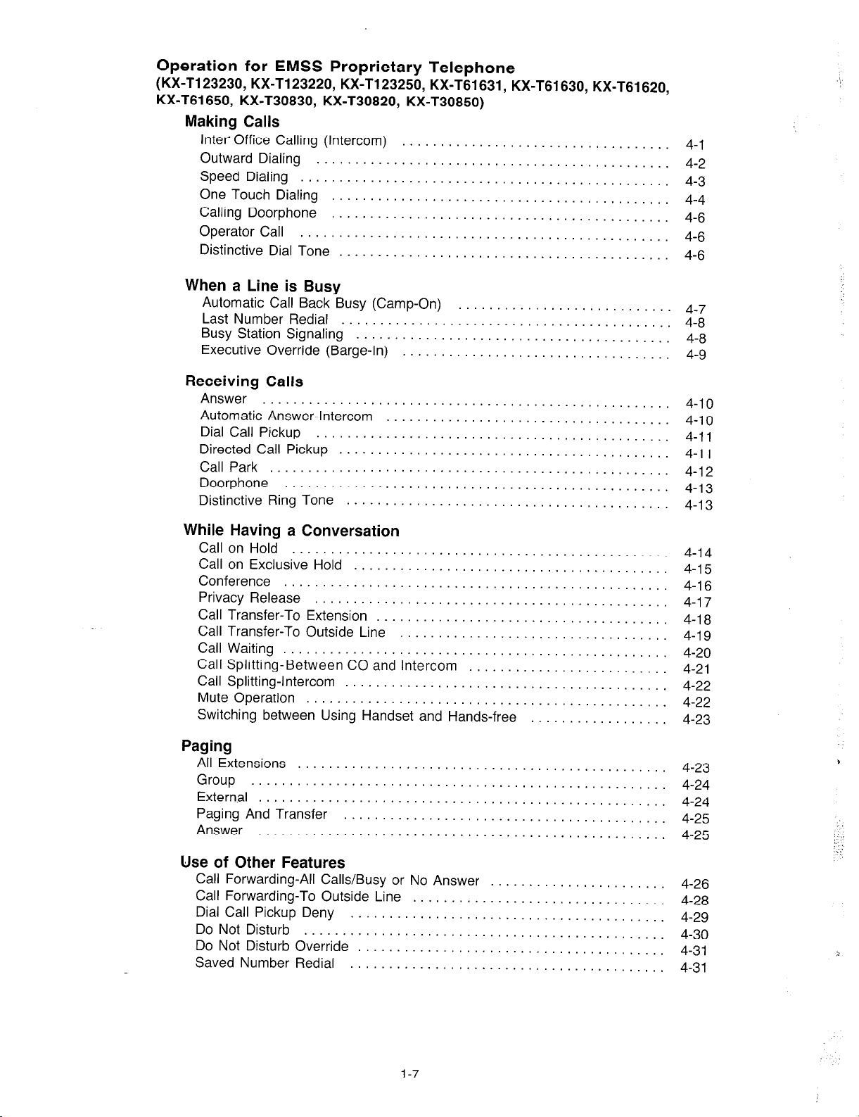
Operation for
(KX-T123230, KX-T123220, KX-Tl23250, KX-T61631, KX-T61630, KX-T61620,
KX-T61650, KX-T30830, KX-T30820, KX-T30850)
EMSS Proprietary Telephone
Making Calls
Inter Office Calling (Intercom)
Outward Dialing
Speed Dialing
One Touch Dialing
Calling Doorphone
Operator Call
Distinctive Dial Tone . . . . . . . . . . . . . . . . . . . . . . .
. . . . . . . . . . . . . . . . . . . . . . . . . . .
. . . . . . . . . . . . . . . . . . . . . . . . . . . . . . . . . . . . . . . . . . . . . . . .
. . . . . . . . . . . . . . . . . . . . . . .
. . . . . . . . . . . . . . . . . . . . . .
. . . . . . . . . . . . . . . . . . . . . . .
. . . . . . . . . . . . . . . . . . .
When a Line is Busy
Automatic Call Back Busy (Camp-On)
Last Number Redial
Busy Station Signaling . . . . . . . .
Executive Override (Barge-In)
. . . . . . . . . .
. .
....................
....................
....................
....................
......
......
......
......
Receiving Calls
Answer
Automatic Answer-Intercom
Dial Call Pickup
Directed Call Pickup . . . . .
Call Park . . .
Doorphone
Distinctive Ring Tone . . .
. . .
. . .
. . . . . . . . . .
. . .
. .
. .
. .
.
. . .
.
. .
. .
. .
.
. .
. .
.
. .
. .
.
. . .
.
.
. .
.
.
. .
. .
. . .
. .
4-1
4-2
4-3
4-4
4-6
4-6
4-6
4-7
4-8
4-8
4-9
4-10
4-10
4-11
4-l 1
4-12
4-13
4-13
While Having a Conversation
Call on Hold
Call on Exclusive Hold
Conference
Privacy Release
Call Transfer-To Extension
Call Transfer-To Outside Line
Call Waiting
Call Splitting-Between CO and Intercom
Call Splitting-Intercom
Mute Operation
Switching between Using Handset and Hands-free
.................................................
.........................................
..................................................
..............................................
......................................
...................................
..................................................
..........................................
...............................................
Paging
All Extensions . . . . .
Group . . . . . . . . . . . . . . . .
External . . . . . . . . .
Paging And Transfer .
Answer . . .
. .
......
......
......
......
Use of Other Features
Call Forwarding-All Calls/Busy or
Call Forwarding-To Outside Line
Dial Call Pickup Deny
Do Not Disturb . . . . . .
Do Not Disturb Override . . .
Saved Number Redial
. . .
. . .
No Answer .
............
............
............
............
............
..........................
.................. 4-23
..............
..............
..............
..............
..............
. .
. . .
. . .
. . .
. .
. .
. .
. . .
. . .
.
. . .
......
......
......
......
......
4-14
4-15
4-16
4-17
4-l 8
4-19
4-20
4-21
4-22
4-22
4-23
4-24
4-24
4-25
4-25
. 4-26
. 4-28
. 4-29
4-30
4-31
. 4-31
1-7
Page 9
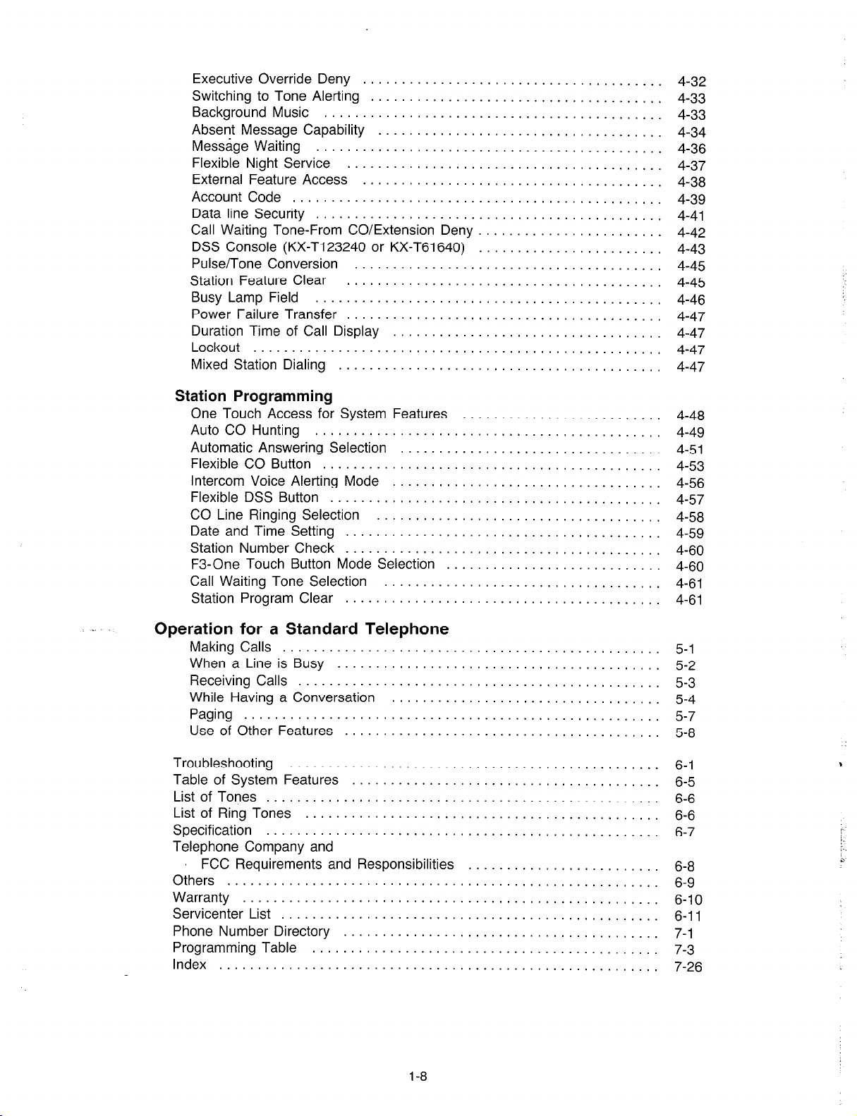
Executive Override Deny
Switching to Tone Alerting
Background Music
Absent Message Capability
Message Waiting
Flexible Night Service
External Feature Access
Account Code
Data line Security
Call Waiting Tone-From CO/Extension Deny
DSS Console (KX-T123240 or KX-T61640)
Pulse/Tone Conversion
Station Feature Clear
Busy Lamp Field
Power Failure Transfer
Duration Time of Call Display
Lockout ...................................................
Mixed Station Dialing
...........................................
..............................................
...........................................
...........................................
.....................................
....................................
..........................................
...................................
.......................................
.....................................
......................................
.......................................
.......................................
.................................
........................................
Station Programming
One Touch Access for System Features
Auto CO Hunting ..................
Automatic Answering Selection .......
Flexible CO Button .................
Intercom Voice Alerting Mode ........
Flexible DSS Button ................
CO Line Ringing Selection ..........
Date and Time Setting ..............
Station Number Check ..............
F3-One Touch Button Mode Selection .
Call Waiting Tone Selection .........
Station Program Clear ..............
......................
......................
. .
.
. .
. .
. . .
. . .
. .
.
.
. .
. . .
. . . .
. .
. .
.
. . .
. .
. . .
. . . .
. . . .
.
.
. . . .
. . . .
. . .
. .
. .
. . . .
. . .
. . .
. . .
. 4-32
. 4-33
4-33
4-34
. 4-36
. 4-37
. 4-38
4-39
. 4-41
. 4-42
. 4-43
. 4-45
. 4-45
. 4-46
. 4-47
. 4-47
. 4-47
4-47
4-48
4-49
4-51
4-53
4-56
4-57
4-58
4-59
4-60
4-60
4-61
4-61
Operation for a Standard Telephone
Making Calls ........................
When a Line is Busy .................
Receiving Calls ......................
While Having a Conversation ..........
Paging .............................
Use of Other Features ................
Troubleshooting ......................
Table of System Features ..............
List of Tones .........................
List of Ring Tones ....................
Specification .........................
Telephone Company and
FCC Requirements and Responsibilities
Others ..............................
Warranty ............................
Servicenter List .......................
Phone Number Directory ...............
Programming Table ...................
Index ...............................
. . . .
. . .
. .
. .
. .
. . . . .
. . .
. . .
.
.
.
. . .
. . . . . .
. . .
. . . .
. .
.
.
. . .
. . .
.
. . .
. .
. . . .
. .
.
. . .
. . . .
. .
. . .
. .
. .
. .
. . .
. .
.
. .
. .
. . . .
. . .
. . .
. . .
. .
.
. .
.
. 6-9
. . 6-11
. 7-3
. . 7-26
5-l
. 5-2
. 5-3
. 5-4
. 5-7
5-8
. 6-1
. 6-5
6-6
6-6
6-7
. 6-8
. 6-10
. 7-l
,
1-8
Page 10
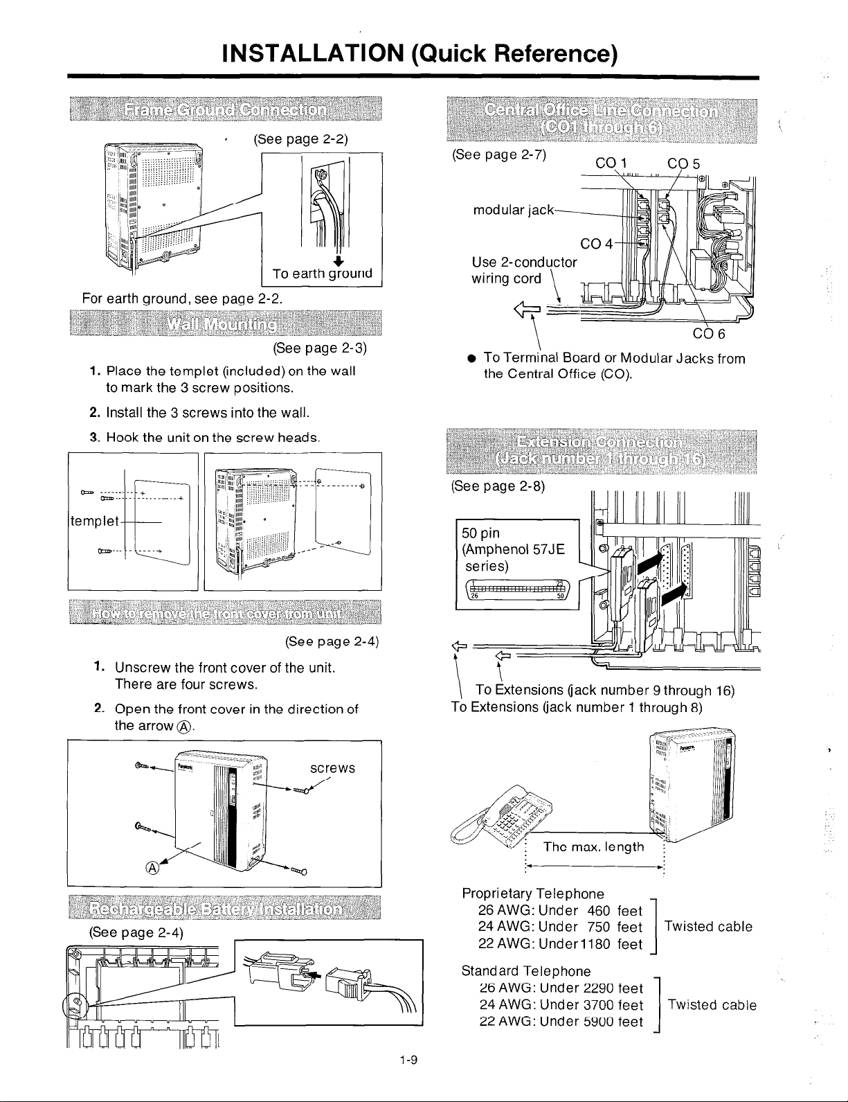
INSTALLATION (Quick Reference)
(See page 2-2)
For earth ground, see page 2-2.
(See page 2-7)
modul
Use 2.
wiring
(See page 2-3)
1. Place the templet (included) on the wall
to mark the 3 screw positions.
2. Install the 3 screws into the wall.
3. Hook the unit on the screw heads.
b . _ . . . +
- . . . . . . . . . --__A
templet
b___ ____*
El
(See page 2-4)
1. Unscrew the front cover of the unit.
There are four screws.
2. Open the front cover in the direction of
the arrow @.
l
To Terminal Board or Modular Jacks from
the Central Office (CO).
(See page 2-8)
To Extensions (jack number 9 through 16)
To Extensions (jack number 1 through 8)
\
CC6
I
(See page 2-4)
Proprietary Telephone
24
AWG: Under
22 AWG: Under
26 AWG: Under 460 feet
Standard Telephone
24 AWG: Under 3700 feet Twisted cable
22 AWG: Under 5900 feet
26 AWG: Under 2290 feet
750 feet Twisted cable
1180 feet
1
1
Page 11
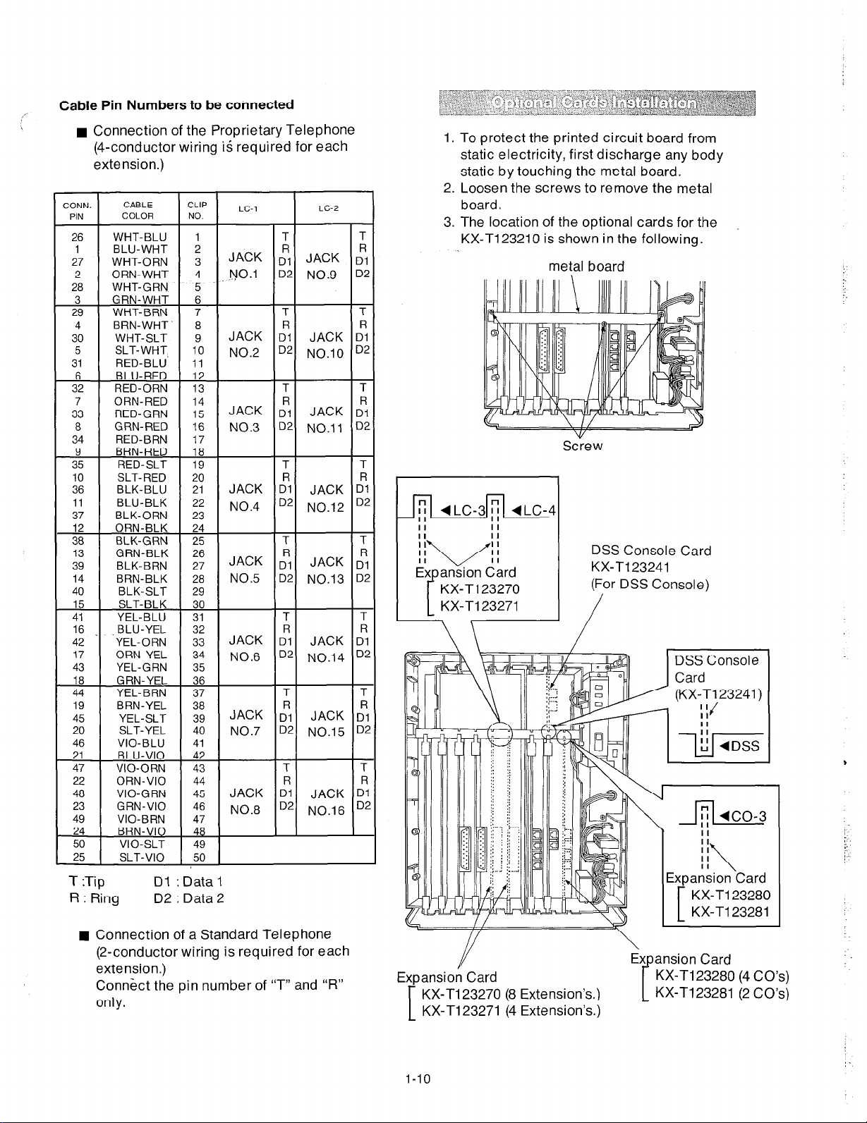
Cable Pin Numbers to be connected
n
Connection of the Proprietary Telephone
(4-conductor wiring is required for each
extension.)
12
18
24
30
36
42
CLIP
NO.
7
8
9
10
11
13
14
15
16
17
19
20
21
22
23
25
26
27
28
29
31
32
33
34
35
37
38
39
40
41
43
LC-1
JACK
NO.1
JACK 4
NO.2
JACK D”1
NO.3
JACK :
NO.4
JACK Dy
NO.5
JACK :
NO.6
JACK ;I
NO.7
I
;l JACK ;A
D2 NO.9 D2
D2 NO.10 D2
D2 NO.11 Dz
D2 NO.12 D4
D2 NO.13 D4
D2 NO.14 D4
JACK D”1 JACK D?
NO.8
2ONN.
PIN
26 WHT-BLU
1 BLU-WHT
27 WHT-ORN
2 ORN-WHT
28 WHT-GRN
3 GRN-WHT
29 WHT-BRN
4 BRN-WHT‘
30 WHT-SLT
5 SLT-WHT
31 RED-BLU’
6 BLU-RED
32 RED-ORN
7 ORN-RED
33 RED-GRN
8 GRN-RED
34 RED-BRN
42 -
17
43 YEL-GRN
19
45 YEL-SLT
20 SLT-YEL
46
CABLE
COLOR
YEL-ORN
ORN-YEL
BRN-YEL
VIO-BLU
ORN-VI0 44
VIO-GRN 45
GRN-VI0 46
LC-2
I
T
T
T
T
JACK D”1
T
T
JACK D”1
T
T
JACK :
T
T
JACK D”1
T
T
JACK ti
T
T
JACK c1”1
D2 NO.15 D;
T
T
D2 NO.16 D;
1.
To protect the printed circuit board from
static electricity, first discharge any body
static by touching the metal board.
2.
Loosen the screws to remove the metal
board.
The location of the optional cards for the
3.
KX-T123210 is shown in the following.
metal board
Screw
DSS Console Card
KX-T123241
I
(For DSS Console)
/
R : Ring
D2 : Data 2
Connection of a Standard Telephone
(2-conductor wiring is required for each
extension.)
Connect the pin number of “T” and “R”
only.
//
Y
Expansion Card
KX-T123270 (8 Extension’s)
KX-T123271 (4 Extension’s)
[
l-10
\
Expansion Card
KX-I123280 (4 CO’s)
KX-Tl23281 (2 CO’s)
1
A
Page 12
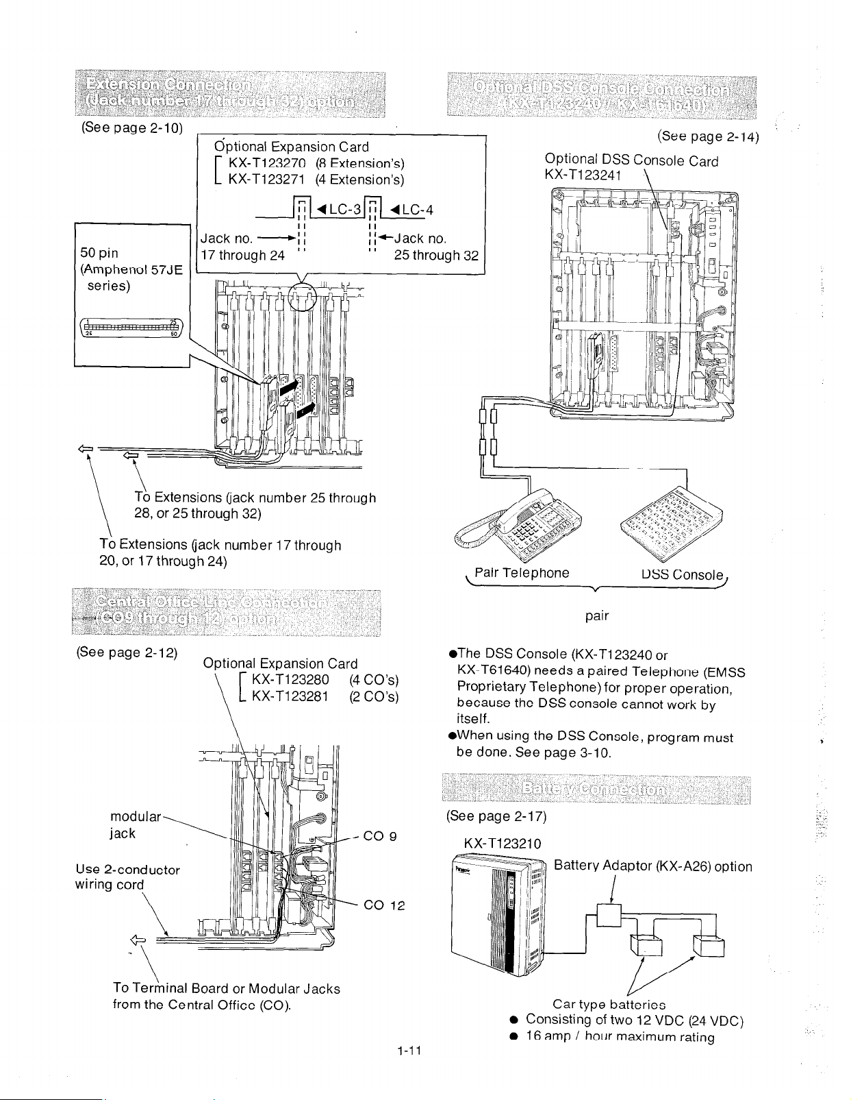
(See page 2-10)
50 pin
(Amphenol 57JE
series)
Extensions (jack number 25 through
, or 25 through 32)
optional Expansion Card
KX-T123270 (8 Extension’s)
KX-T123271 (4 Extension’s)
II
Jack no. -ii
17 through 24
’ ’
(See page 2-14)
Optional DSS Console Card
To Extensions (jack number 17 through
20, or 17 through 24)
(See page 2-12)
Optional Expansion Card
KX-Tl23280 (4 CO’s)
KX-Tl23281 (2 CO’s)
Use 2-conductor
Pair Telephone
DSS Console
v
pair
l
The DSS Console (KX-Tl23240 or
KX-T61640) needs a paired Telephone (EMSS
Proprietary Telephone) for proper operation,
because the DSS console cannot work by
itself.
l
When using the DSS Console, program must
be done. See page 3-10.
(See page 2-17)
KX-T123210
Battery Adaptor (KX-A26) option
t
To Terhinal Board or Modular Jacks
from the Central Office (CO).
I-11
Car type batteries
l
Consisting of two 12 VDC (24 VDC)
l
16 amp / hour maximum rating
Page 13
(See page 2-l 5.) ’
1 Doorphone Adaptor
(KX-i30860D only)
CPU
Card
After drawing a
CPU Card, insert
adaptor connector
into connector on
the CPU Card. .
4-conductor wiring
(See page 2-18.)
KX-Tl23210
Serial Printer
Serial Interface
(RS-232C)
l
Cables must be shielded and the maximum
length is 6.5 feet.
Connection Chart:
KX-Tl23210 RS-232C
Pin
No.
1
2
3
5
Printer RS-232C
!ror, zirmai Type
-1 FG
-3 RXD
-2 TXD
Circuit
(El A)
AA
BB
BA
Doorphone
The max. length
4 *
26 AWG : Under 230 feet
24 AWG : Under 370 feet Twisted cable
22 AWG : Under 590 feet
Paging Equipment 2 u
(See page 2-20.)
KX-Tl23210
20 DTR
-7 SG
5 CTS
CD DTR
46
7
20
6 DSR
7 8 1 DCD 1 CF 1
I
I
Communication parameters
If the Panasonic printer which is used has a
(KX-
Pl 1 D or KX- P17) board and is connected
to the KX-Tl23210, set the communication
parameters the following.
KX-PI 1 D
\
Word
length
Parity
Baud
Rate
KX-Tl23210 DIP
ISwitch
7bit SWl-1
(default)
Program to SWl-2
“EVEN”
(see page
3-32.) SWl-3
1200B SWl-5
(default) SWl-6
SWl-7
SWl-8
Setting Switch Setting
ON SWl-4 ON
ON SWl-5 OFF
ON SWl-6 OFF
ON SWl-1 OFF
OFF SWl-2 OFF
OFF SWl-3 ON
OFF
DIP
CD
AB
CB
CC
I
KX-P17
I
EXT dusic Jack
l-l
Protocol
XON I SW2-8
XOFF
mode only
OFF SWl-8 ON
I
I
I
I
Page 14
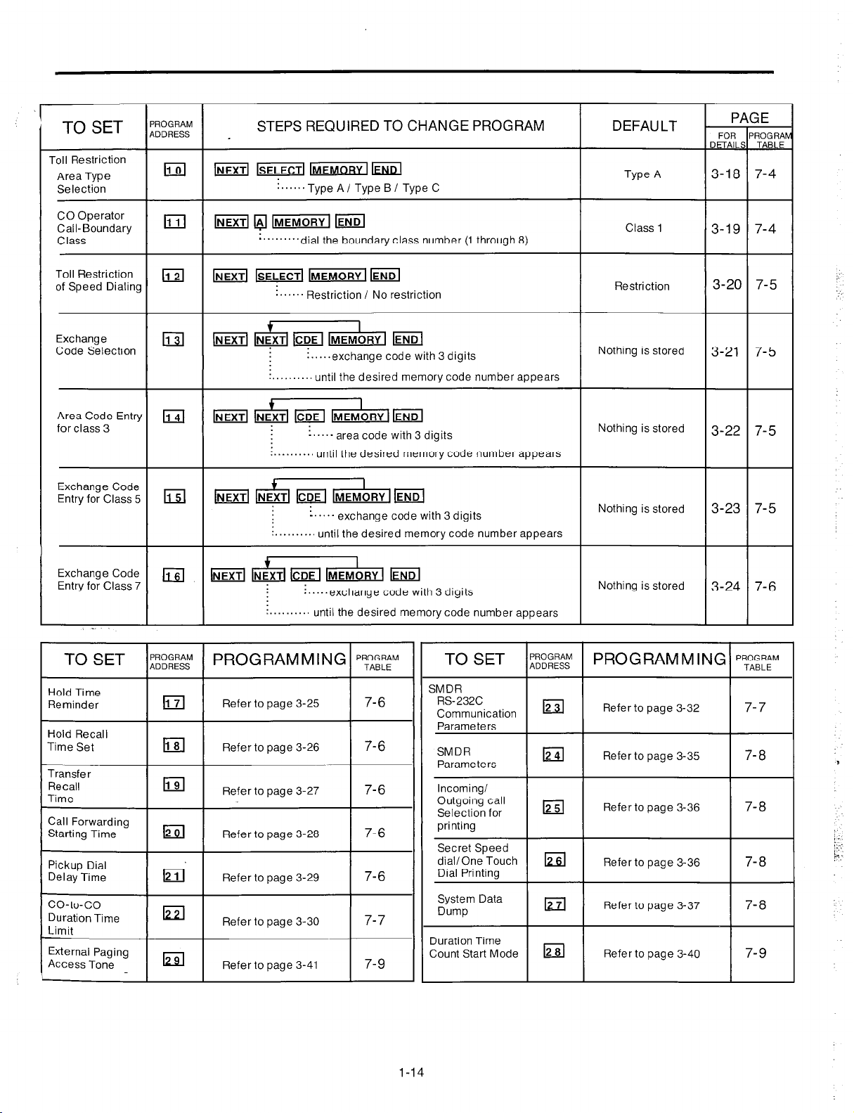
System Feature
TO SET
Iate and Time
jetting
PROGRAM
ADDRESS ,
PROGRAMMING (Quick Reference)
STEPS REQUIRED TO CHANGE PROGRAM
:....
n..‘year
!...month
:...,-jay
:.-day
of
the week
hour
DEFAULT
/
FOR
DETAIL’
3-4
P,
AGE
2
?RAb
BLE
-
System Speed
Iialing Entry
Extension
Number
Assignment
Iperator
qssignment
‘aired Telephone
jssignment for
ISS Console
Uomatic
M&king
lay/Night Service
vlode
Switching of
Service Mode
Starting Time
CO
DSS bd
’
i .._ minute
............. Speed access code (00 through 99)
~ IMEMOBY]~END
:.....dial the extension number (lOOthrough 199)
:.........,until the desired jack number appears
lo
_..._ dial the jack number which is set operator
_.....
until the desired operator number appears
:. jack number paired with console 1
kkd kk@ m hd
“““With Transfer / Without Transfer
‘.““Manual / Automatic
i . . . ..- AM / PM
q q
1
:
access number of
Trunk Group
!..... jack number paired
with console 2
Nothing is stored
101 : jack number 01
102 : jack number 02
131 : jack number 31
132 : jack number 32
Nothing is stored
jack number 01
:
console 1
jack number 02
:
console 2
With Transfer
Manual
3-5
3-8
3-9
3-10
3-11
3-12
1
-
3
3
I
3
3
-
4
-
Zall Hunting
Setting
Hunting Type
n...minute ...... AM I PM
:. -
starting time for night service (hour)
Ga = Disable : all 8
-......-
lzl La
:.......... Disable / Enable extension
until the desired extension group number appears
. . . . . ..Terminate / Circular
. . . .
until the desired extension group number appears
1-13
Terminate : all 8
groups
extension
groups
3-15
3- 16
4
4
4
-
Page 15
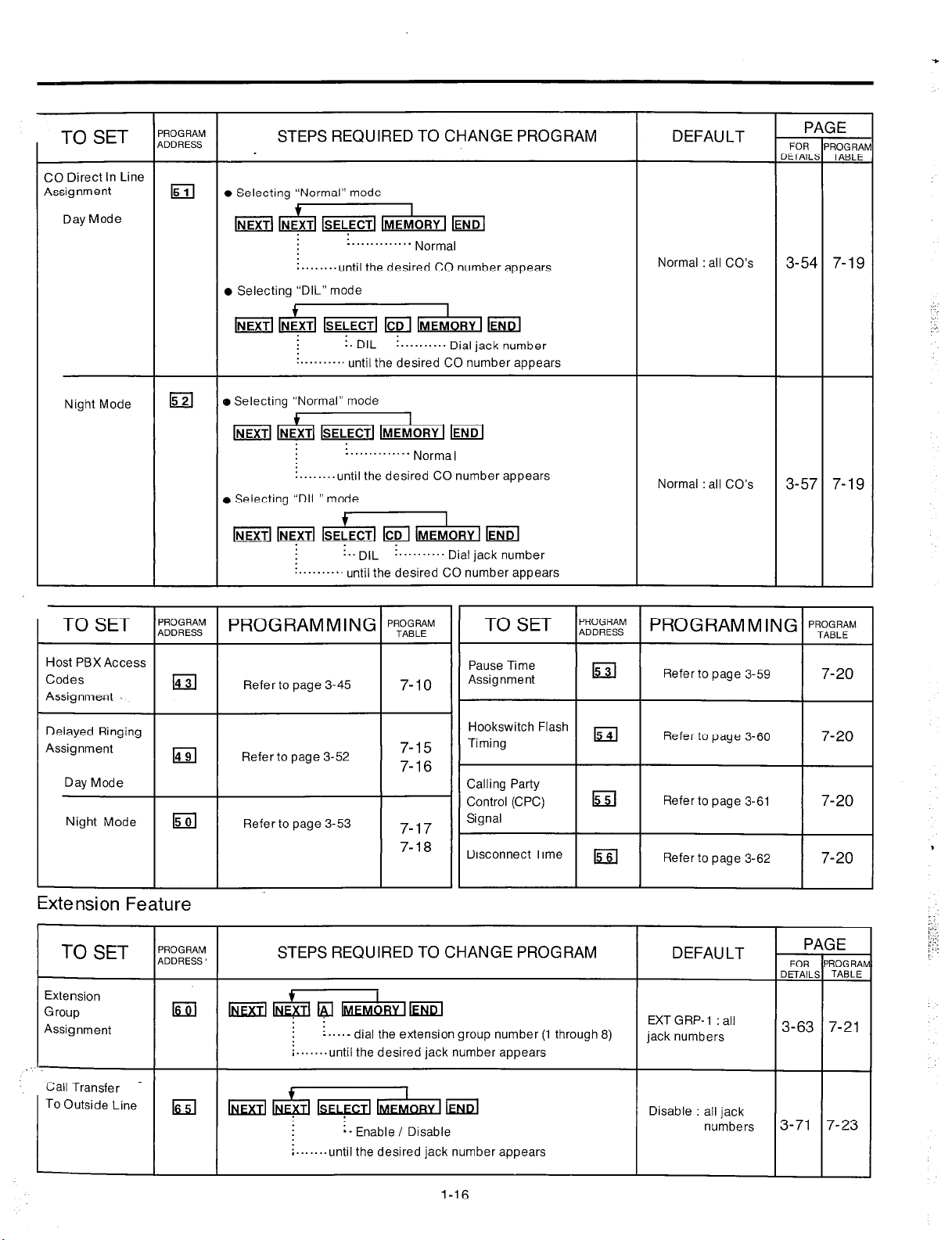
TO SET
Toll Restriction
Area Type
Selection
‘ROGRAM
DDRESS
STEPS REQUIRED TO CHANGE PROGRAM
,
[NEXTIkiyiKmm
. . . . . ..Type A/ Type B I Type C
DEFAULT
Type A
l-
FOR
DETAIL:
3-18
P/
SE
FiOGRAh
TABLE
7-4
1
CO Operator
Call-Boundary
Class
Toll Restriction
of Speed Dialing
Exchange
Code Selection
Area Code Entry
for class 3
Exchange Code
Entry for Class 5
Exchange Code
Entry for Class 7
lNEXTll$lKiFlllhnEMORY
‘.........dial the boundary class number (1 through 8)
lNEXTl~llYlEMORYI
....... Restriction / No restriction
~
:.....exchange code with 3 digits
: . . . . . . . . .
&id
-‘....
:........., until the desired memory code number appears
-....- exchange code with 3 digits
:........., until the desired memory code numberappears
lCDE
i.....exchange code with 3 digits
:........., until the desired memorycode number appears
I
IMEM~R~I lENDl
until the desired memory code number appears
I
IMEMORY
area code with 3 digits
I lEND
I
IMEMORY I lEND
Class 1
Restriction
Nothing is stored
Nothing is stored
Nothing is stored
Nothing is stored
3-20
7-4
7-5
3-19
3-21 7-5
3-22
7-5
3-23 7-5
3-24
7-6
TO SET l;;;;g ( PROGRAMMINGIpyBEM
Hold Time
Reminder
Hold Recall
Time Set
Pickup Dial
Delay Time
co-to-co
Duration Time
Limit
External Paging
Access Tone
El
I I
IEI
I I
El
Refer to page 3-25
Refer to page 3-26
Refer to
Refer to page 3-30
Refer to page 3-41
page
3-29
7-6
7-6
7-6
7-7
7-9
TO SET
Incoming/
Outgoing call
Selection for
printing
Secret Speed
dial/One Touch m
Dial Printino
System Data
Dump
Duration Time
Count Start Mode
I I
;“,“,;;;; PRO G RAM M I NC
12
12
12
Refer to page 3-36
Refer to page 3-36
Refer to page 3-37
Refer to page 3-40
i
‘ROGRAM
I
TABLE
7-8
7-8
7-8
7-8
l-14
Page 16

Outside Line Feature
TO SET
CO Connection
Assignment
ROGRAM
ODRESS
14
STEPS REQUIRED TO CHANGE PROGRAM
I
-1 IMEMORY I /EiEl
‘..“.‘....‘.-
i........until the desired CO number appears
Connect / Not Connect
D EFAU LT
Connect : all CO’s
T
m
3-42
PAGE
FOR
ROGRA
w
7-9
Iial Mode
DTM F/ Pulse)
DTMF / Pulse
Selection
Pulse Speed
Selection
Trunk Group
Assignment
Flexible
Outward Dialing
Assignment
Day Mode
Iid
14
(4
la
@KZl IMFMORY
!..........DTMF Mode / Pulse Mode
o..........until the desired CO number appears
: .......... Low Speed / High Speed
: .......... until the desired CO number appears
; ......... dial the trunk group number (1 through 8)
....... until the desired CO number appears
other CO number
:......Enabl e / Disable
:......unti I the desired jack number appears
:-.....-until the desired CO number appears
other CO number
I kcd
I
DTMF : all CO’s
Low speed : all CO’s
‘runk-Gl
‘runk-G2
‘runk-G3
‘runk-G4
‘runk-GS
.runk-G6
.runk-G7 : CO 7
‘runk-G8 : CO 8, CO
Enable : all jack
co1
co2
co3
co4
co5
CO6
co
10, co 1
co 12
numbers
5
3-43
3-44
3-46
3-47
7-9
7-9
7-1c
/
7-11
Night Mode
Flexible Ringing
Assignment
Day Mode
Night Mode
La
(4
i......Enabl e / Disable
:......unti I the desired jack number appears
:......-unti I the desired CO number appears
other CO number
other jack number
w /NEXTI Ia
m F UT [MFMoRY’IFJJKJ
*
:......Enable / Disable
:......until the desired jack number appears
i......-until the desired CO number appears
other CO number
other jack number
t
:......Enable / Disable
:......until the desired jack number appears
:......-until the desired CO number appears
I
Enable all jack
Enable : all jack
Enable : all jack
numbers
numbers
numbers
3-48 7-12
3-49
7-13
3-51 7-14
Page 17
TO SET
CO Direct In Line
Assignment
Day Mode
l-
‘ROGRAM
,DDRESS
1511
STEPS REQUIRED TO CHANGE PROGRAM DEFAULT
l
Selecting “Normal” mode
+
I
lNEXTl&lSELECTllNlEMORYI
:........until the desired CO number appears
l
Selecting “DIL” mode
: . . . . . . . . . . . . .
Norma,
Normal : all CO’s
T
PI
FOR
IETAILE
3-54 7-19
;E
ROGRAh
TABLE
Night Mode
Host PBX Access
Delayed Ringing
Assignment
Day Mode
Night Mode
El
14
15
lsELECTl ICDI
!. DIL
:..........
o Selecting “Normal” mode
until the desired CO number appears
: . . . . . . . . . . . . .
:........until the desired CO number appears
. Selecting “DIL” mode
: .. DIL
........... until the desired CO number appears
PROGRAMMING
Refer to page 3-45
Refer to page 3-52
Refer to page 3-53
IMEMORY I Eid
! . . . . Dial jack number
Norma,
: .......... Dial jack number
‘ROGRAM
TABLE
Pause Time
7-10
7-15
Assignment
Hookswitch Flash
Timing
7-16
Calling Party
Control (CPC) w
7-17
7-18
Signal
Disconnect Time lss]
15
I I
I I
Normal : all CO’s
Refer to page 3-59
Refer to page 3-60
Refer to page 3-61
Refer to page 3-62
3-57 7-19
7-20
I
7-20
7-20
7-20
Extension Fea
TO SET
Extension
Group
Assignment
Call Transfer _
TO
Outside Line
I
ure
‘ROGRAM
,DDRESS
El
kzil
STEPS REQUIRED TO CHANGE PROGRAM
i....- dial the extension group number (1 through 8)
i.......until the desired jack number appears
f
‘““‘yTMm
:- Enable / Disable
i.......until the desired jack number appears
DEFAULT
EXT G RP- 1 : all
jack numbers
FOR
DETAIL:
3-63
PI
SE
‘ROG RAP
TABLE
7-21
1
I
Disable : all jack
numbers
1-16
3-71 7-23
Page 18
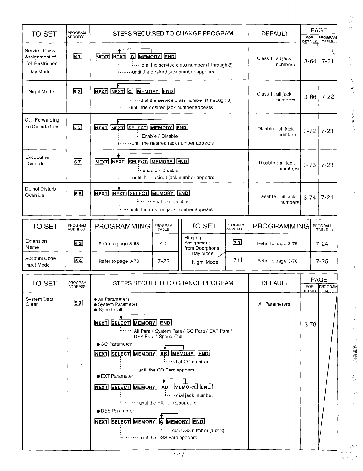
TO SET
Service Class
Assignment of
Toll Restriction
Day Mode
ROGRAM
DDRESS
1611
STEPS REQUIRED TO CHANGE PROGRAM
pa+ii&lm
i....
dial the service class number (1 through 8)
;-......until the desired jack number appears
DEFAULT
Class 1 : all jack
numbers
T
IETAIL’
A
3-64
FOR
t
7-21
Night Mode
Call Forwarding
To Outside Line
Excecutive
Override
Do not Disturb
Override
I
El
IGil
la
Ed
++z&lW
6lb-m
:....-dial the service class number (1 through 8)
;.......until the desired jack
: -
Enable / Disable
;.......until the desired jack number appears
number
appears
I
ml
;.......until the desired jack number appears
IMEM~RY 1 EiiiZl
i-
Enable / Disable
I
1-1
*.....’ until the desired jack number appears
IP.~EMoRY I @El
:......-
Enable / Disable
Class 1 : all jack
numbers
Disable : all jack
numbers
Disable : all jack
number?
Disable : all jack
number!
( TO SET I;“,;;:&! 1 PROGRAMMING 1 pyBy I( TO SET I;;“,;;;: 1 PROGRAMMING
7-22
3-66
3-72 7-23
3-73
3-74
7-23
7-24
‘ROGRAM
TABLE
TO SET
System Data
Clear
‘ROGRAM
,DDRESS
STEPS REQUIRED TO CHANGE PROGRAM
l
All Parameters
0 System Parameter
l
Speed Call
~ &+&l lEND
..““” All Para I System Para I CO Para I EXT Para I
DSS Parai Speed Call
0 CO Parameter
=I-_
.........- until the CO Para appears
o EXT Parameter
n.....dial CO number
I
~ F liiiiza g bFMORYl kJ!d
:.,.,-dial jack number
:..........until the EXT Para appears
l
DSS Parameter
+
I
~~~tt$hWdEl!d
:....-dial DSSnumber (1 or 2)
:........- until the DSS Para appears
DEFAULT
All Parameters
FOR
,ETAILI
3-78
ROGRAI
aku
1-17
Page 19
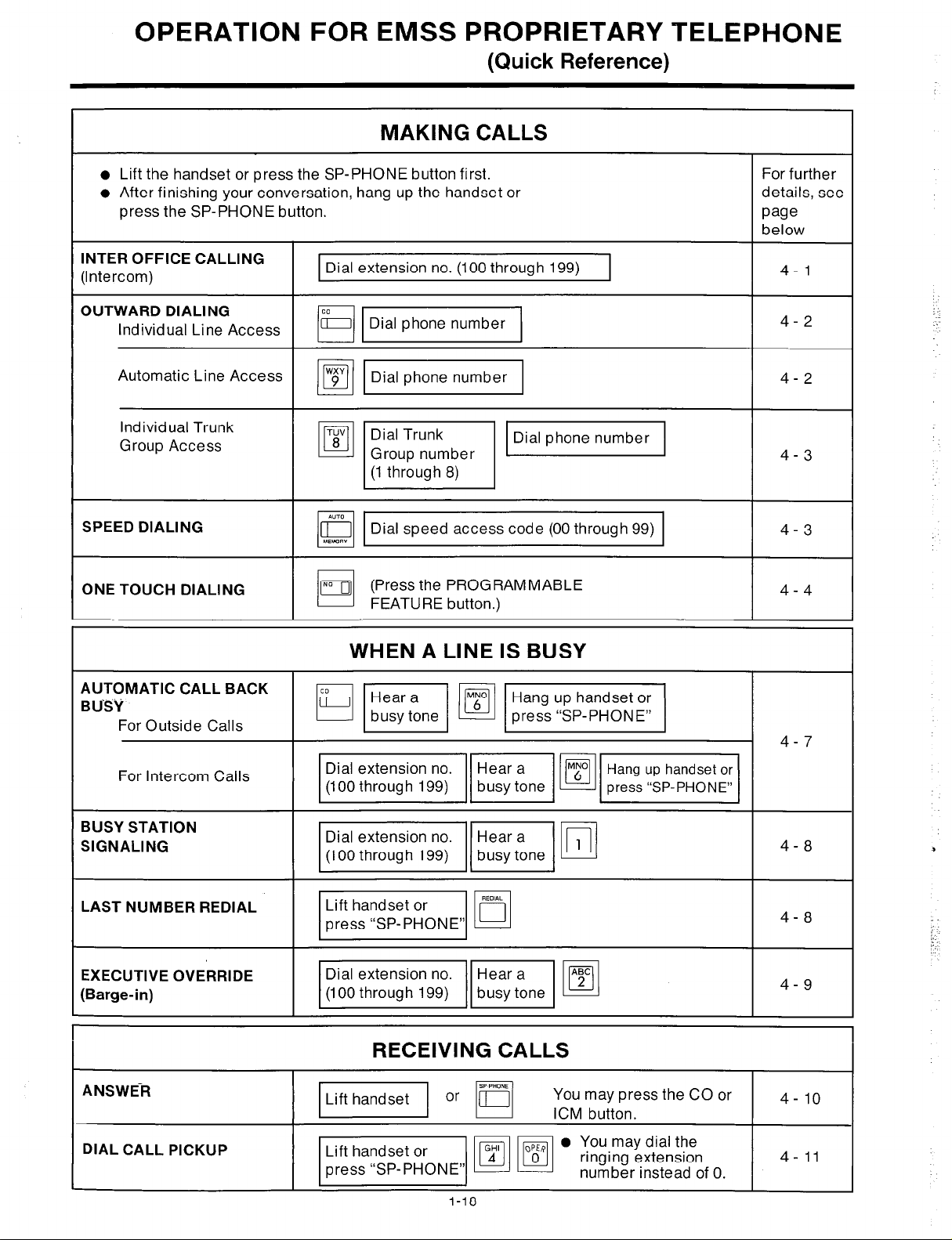
OPERATION FOR EMSS PROPRIETARY TEbEPHONE
(Quick Reference)
MAKING CALLS
l
Lift the handset or press the SP-PHONE button first.
l
After finishing your conversation, hang up the handset or
press the SP-PHONE button.
INTER OFFICE CALLING
(Intercom)
OUTWARD DIALING
Individual Line Access
Automatic Line Access
Individual Trunk
Group Access
SPEED DIALING
ONE TOUCH DIALING
Dial extension no. (100 through 199)
m-1
mm
TUV
Dial Trunk
8
lo
Q Dial speed access code (00 through 99)
01
[,,
0
Group number
(1 through 8)
I
l”iD
(Press the PROGRAMMABLE
FEATURE button.)
For further
details, see
page
below
4- 1
4-2
4-2
v
4-3
4-3
4-4
AUTOMATIC CALL BACK
BUSY
For Outside Calls
For Intercom Calls
BUSY STATION
SIGNALING
LAST NUMBER REDIAL
EXECUTIVE OVERRIDE
(Barge-in)
ANSWER
WHEN A LINE IS BUSY
HW@JV/
mmB-1
mvp
pj$$qm
RECEIVING CALLS
m or
q
4-7
4-8
4-8
4-9
4- 10 ;;;;K’;;ssthe CO or
DIAL CALL PICKUP
I-18
Page 20
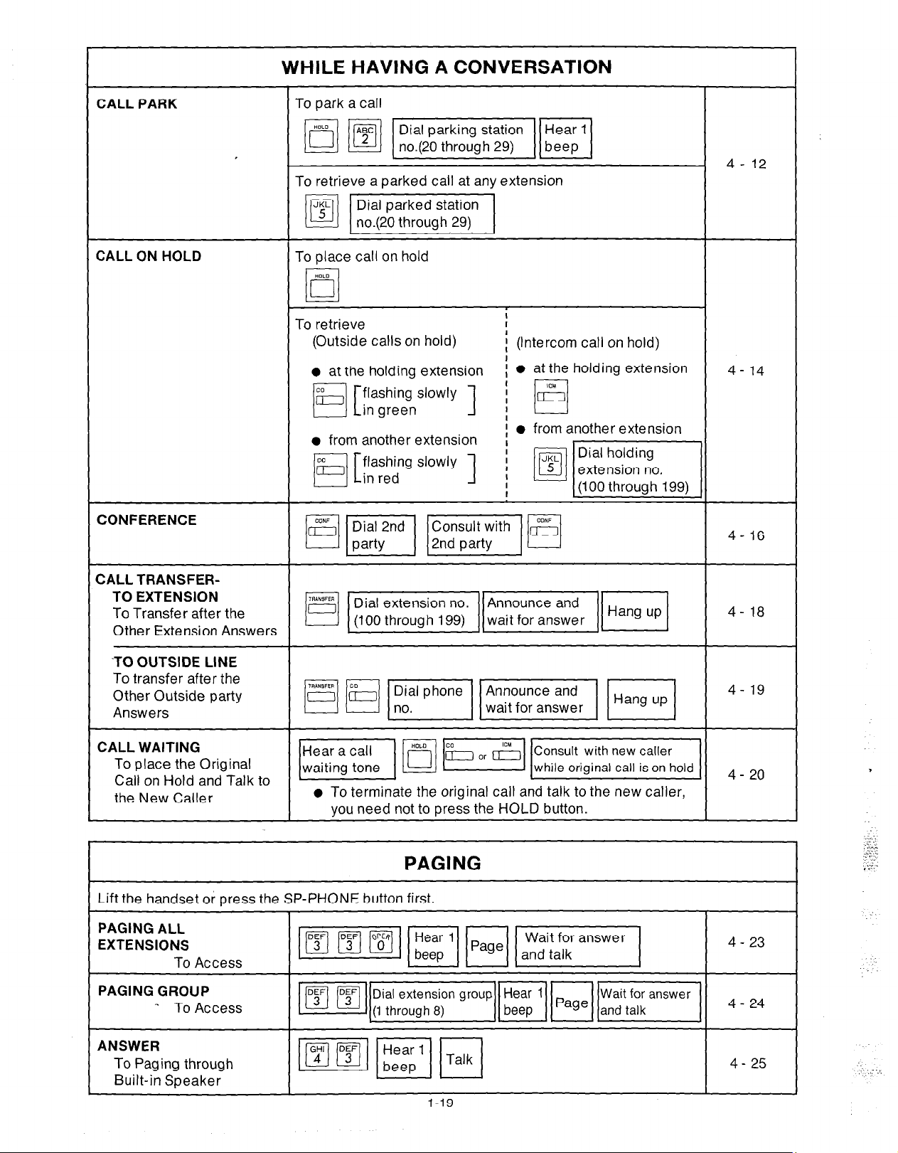
CALL PARK
WHILE HAVING A CONVERSATION
4- 12
To retrieve a parked call at any extension
m-1
CALL ON HOLD
CONFERENCE
CALL TRANSFER-
TO EXTENSION
To Transfer after the
Other Extension Answers
‘TO OUTSIDE LINE
To transfer after the
Other Outside party
Answers
To place call on hold
To retrieve
(Outside calls on hold)
l
at the holdina extension
a from another extension
i
I
i (Intercom call on hold)
I
: l at the holding extension
! l from another extension
4- 14
4- 16
4- 18
4- 19
CALL WAITING
To place the Original
Call on Hold and Talk to
the New Caller
Lift the handset or press t
PAGING ALL
EXTENSIONS
To Access
PAGING GROUP
_ To Access
ANSWER
To Paging through
Built-in Speaker
l
To terminate the original call and talk to the new caller,
you need not to press the HOLD button.
PAGING
he SP-PHONE button first.
4- 20
4 - 23
_./....
.:..
Page 21
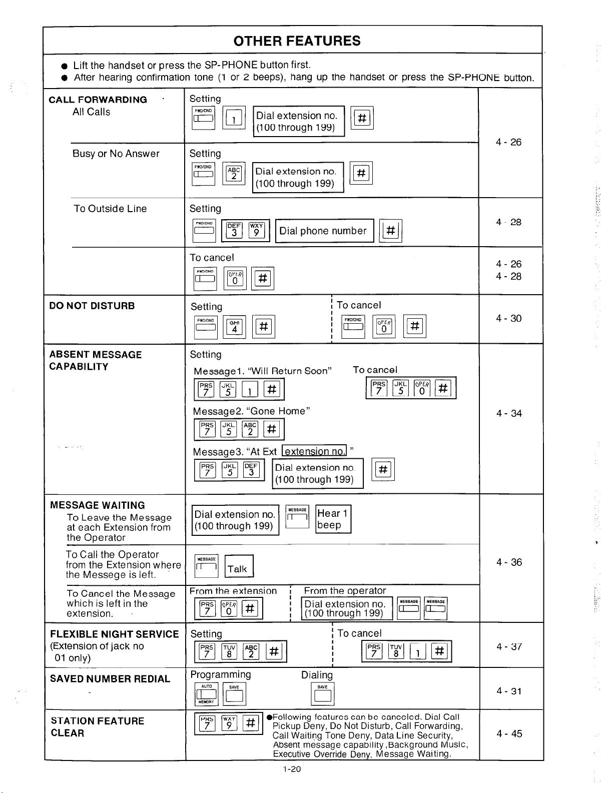
OTHER FEATURES
l
Lift the handset or press the SP-PHONE button first.
l
After hearing confirmation tone (1 or 2 beeps), hang up the handset or press the SP-PHONE button.
CALL FORWARDING *
All Calls
Busy or No Answer
To Outside Line
DO NOT DISTURB
ABSENT MESSAGE
CAPABILITY
Setting
Setting
Setting
To cancel
Setting
Setting
Messagel. “Will Return Soon”
4- 26
4- 28
4- 26
4 - 28
I To cancel
4- 30
To cancel
MESSAGE WAITING
To Leave the Message
at each Extension from
the Operator
To Call the Operator
from the Extension where
the Messege is left.
To Cancel the Message
which is left in the
extension.
FLEXIBLE NIGHT SERVICE
(Extension of jack no
01 only)
SAVED NUMBER REDIAL
Message2. “Gone
Setting
Programming
Home”
4- 36
/;
I To cancel
I
Dialing
STATION FEATURE
CLEAR
l
Following features can be canceled. Dial Call
Pickup Deny, Do Not Disturb, Call Forwarding,
Call Waiting
Absent message capability ,Background Music,
Executive Override Deny. Message
Tone Deny, Data Line Security,
Waiting
I-20
4- 45
Page 22
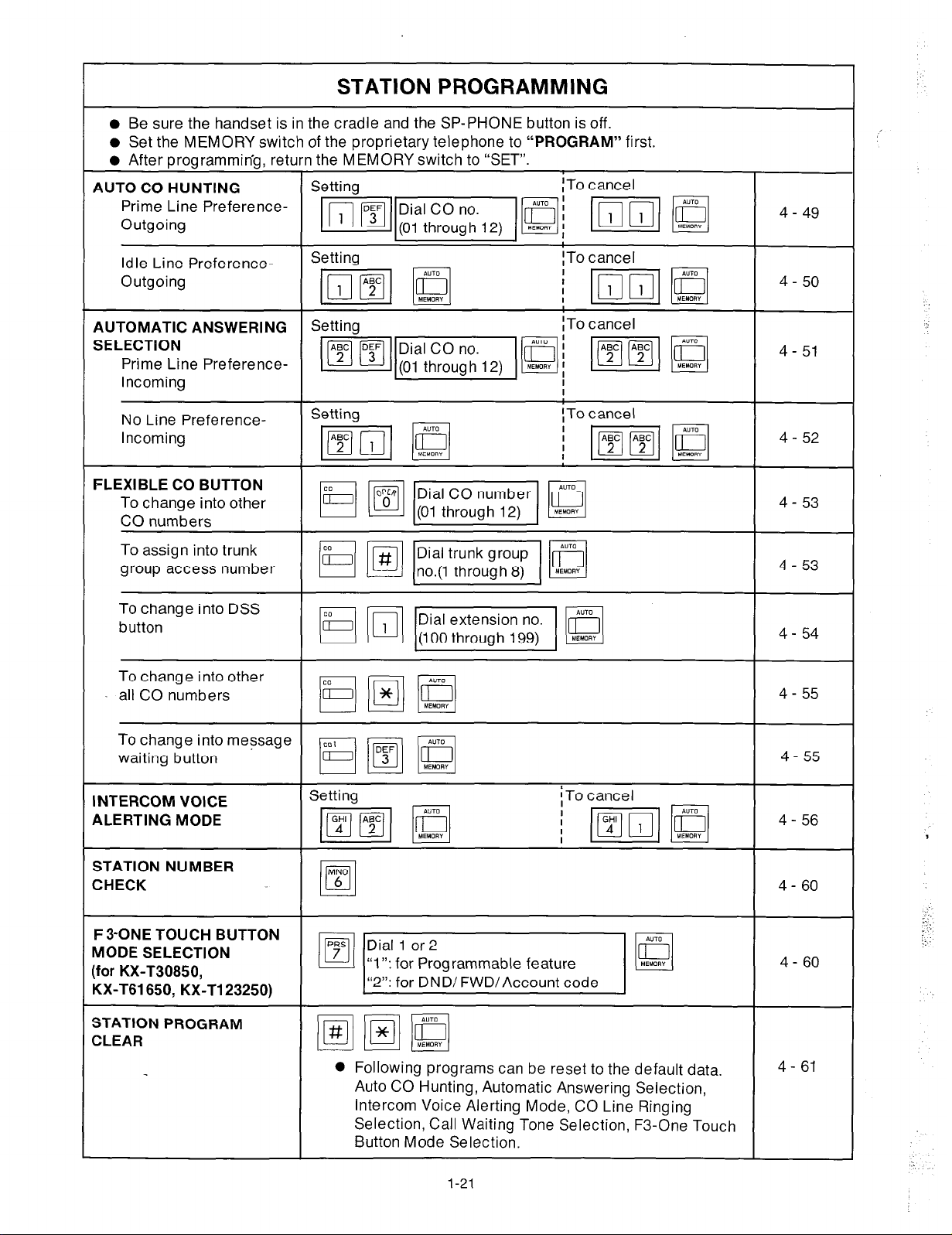
STATION PROGRAMMING
l
Be sure the handset is in the cradle and the SP-PHONE button is off.
l
Set the MEMORY switch of the proprietary telephone to “PROGRAM” first.
l
After programming, return the MEMORY switch to “SET”.
AUTO CO HUNTING
Prime Line PreferenceOutgoing
Setting
~TO cancel
Idle Line PreferenceOutgoing
AUTOMATIC ANSWERING
SELECTION
Prime Line PreferenceIncoming
No Line PreferenceIncoming
FLEXIBLE CO BUTTON
To change into other
CO numbers
To assign into trunk
group access number
To change into DSS
button
To change into other
all CO numbers
Setting
Setting
ITo cancel
ITo cancel
I
!To cancel
;mm
4- 51
4-52
4 - 53
4 - 53
4- 54
4 - 55
To change into message
waiting button
INTERCOM VOICE
ALERTING MODE
STATION NUMBER
CHECK
F3-ONE TOUCH BUTTON
MODE SELECTION
(for KX-T30850,
KX-T61650, KX-T123250)
STATION PROGRAM
CLEAR
Setting
l
Following programs can be reset to the default data.
Auto CO Hunting, Automatic Answering Selection,
Intercom Voice Alerting Mode, CO Line Ringing
Selection, Call Waiting Tone Selection, F3-One Touch
Button Mode Selection.
1-21
4- 55
4- 61
Page 23
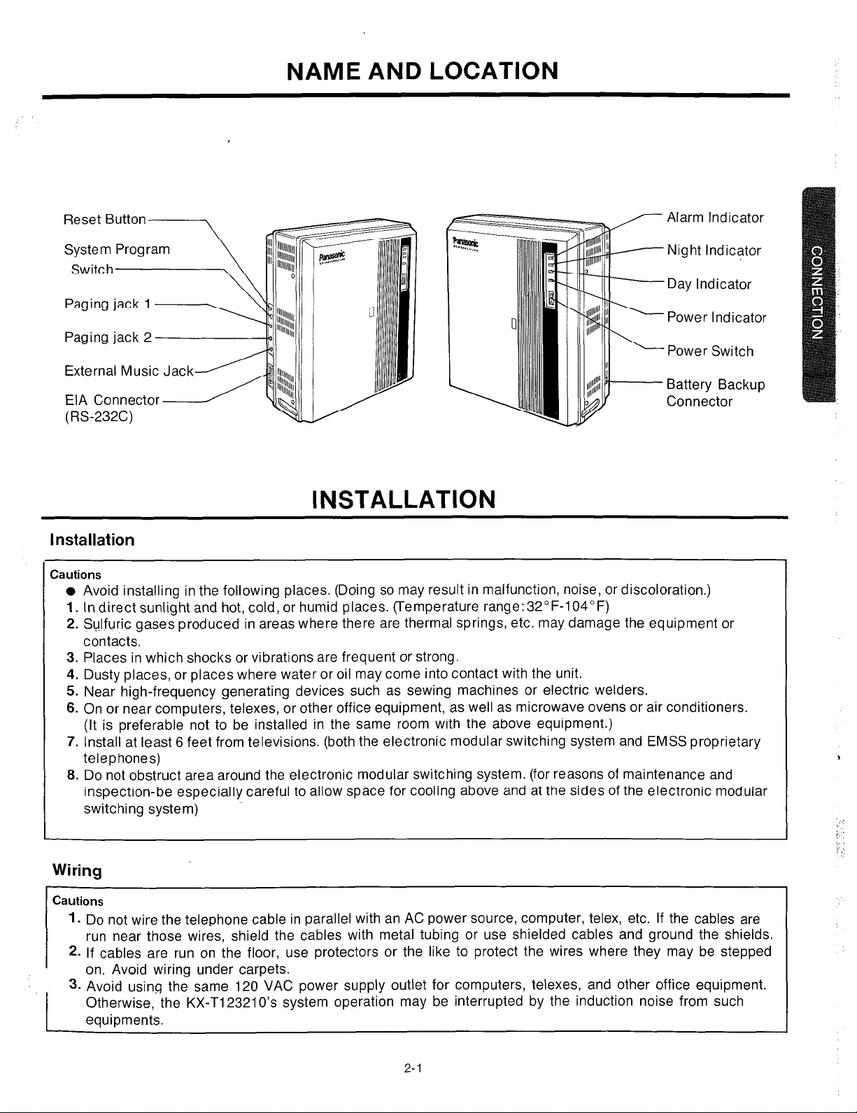
External Music Jack
EIA Connector
(RS-232C)
NAME AND LOCATION
Alarm Indicator
Night Indicator
Day Indicator
Power Indicator
Power Switch
Battery Backup
Connector
INSTALLATION
Installation
Cautions
l
Avoid installing in the following places. (Doing so may result in malfunction, noise, or discoloration.)
1.
Indirect sunlight and hot, cold, or humid places. (Temperature range:32”F-104°F)
2. Sulfuric gases produced in areas where there are thermal springs, etc. may damage the equipment or
contacts.
3. Places in which shocks or vibrations are frequent or strong.
4. Dusty places, or places where water or oil may come into contact with the unit.
5. Near high-frequency generating devices such as sewing machines or electric welders.
6. On or near computers, telexes, or other office equipment, as well as microwave ovens or air conditioners.
(It is preferable not to be installed in the same room with the above equipment.)
7. Install at least 6 feet from televisions. (both the electronic modular switching system and EMSS proprietary
telephones)
8. Do not obstruct area around the electronic modular switching system. (for reasons of maintenance and
inspection-be especially careful to allow space for cooling above and at the sides of the electronic modular
switching system)
Wiring
Cautions
1.
Do not wire the telephone cable in parallel with an AC power source, computer, telex, etc. If the cables are
run near those wires, shield the cables with metal tubing or use shielded cables and ground the shields.
2.
If cables are run on the floor, use protectors or the like to protect the wires where they may be stepped
on. Avoid wiring under carpets.
3.
Avoid using the same
Otherwise, the KX-T123210’s system operation may be interrupted by the induction noise from such
equipments.
120
VAC power supply outlet for computers, telexes, and other office equipment.
t
2-l
Page 24
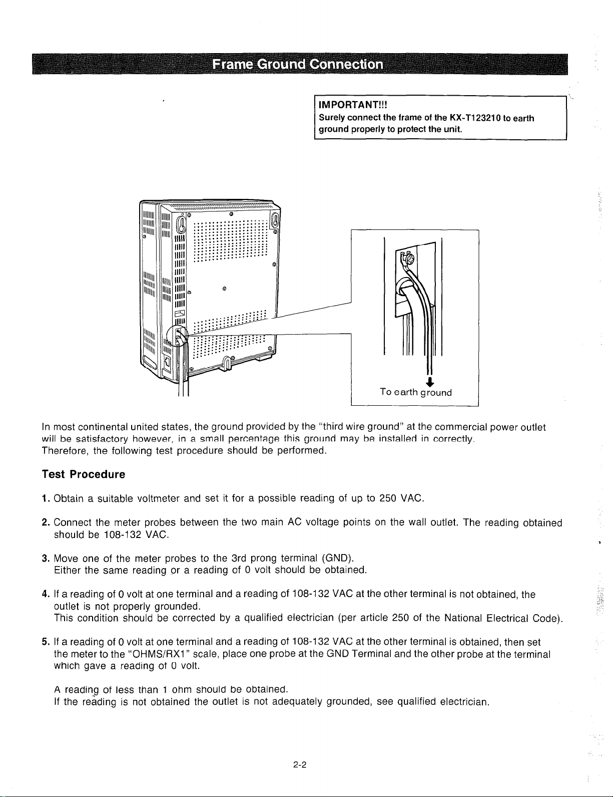
IMPORTANT!!!
Surely connect the frame of the KX-Tl23210 to earth
ground properly to protect the unit.
To earth ground
4
In most continental united states, the ground provided by the “third wire ground” at the commercial power outlet
will be satisfactory however, in a small percentage this ground may be installed in correctly.
Therefore, the following test procedure should be performed.
Test Procedure
1.
Obtain a suitable voltmeter and set it for a possible reading of up to 250 VAC
Connect the meter probes between the two main AC voltage points on the wall outlet. The reading obtained
2.
should be 108-132 VAC.
3.
Move one of the meter probes to the 3rd prong terminal (GND).
Either the same reading or a reading of 0 volt should be obtained.
4.
If a reading of 0 volt at one terminal and a reading of 108-l 32 VAC at the other terminal is not obtained, the
outlet is not properly grounded.
This condition should be corrected by a qualified electrician (per article 250 of the National Electrical Code).
If a reading of 0 volt at one terminal and a reading of 108-l 32 VAC at the other terminal is obtained, then set
5.
the meter to the “OHMS/RX1 ” scale, place one probe at the GND Terminal and the other probe at the terminal
which gave a reading of 0 volt.
A reading of less than 1 ohm should be obtained.
If the reading is not obtained the outlet is not adequately grounded, see qualified electrician.
2-2
Page 25
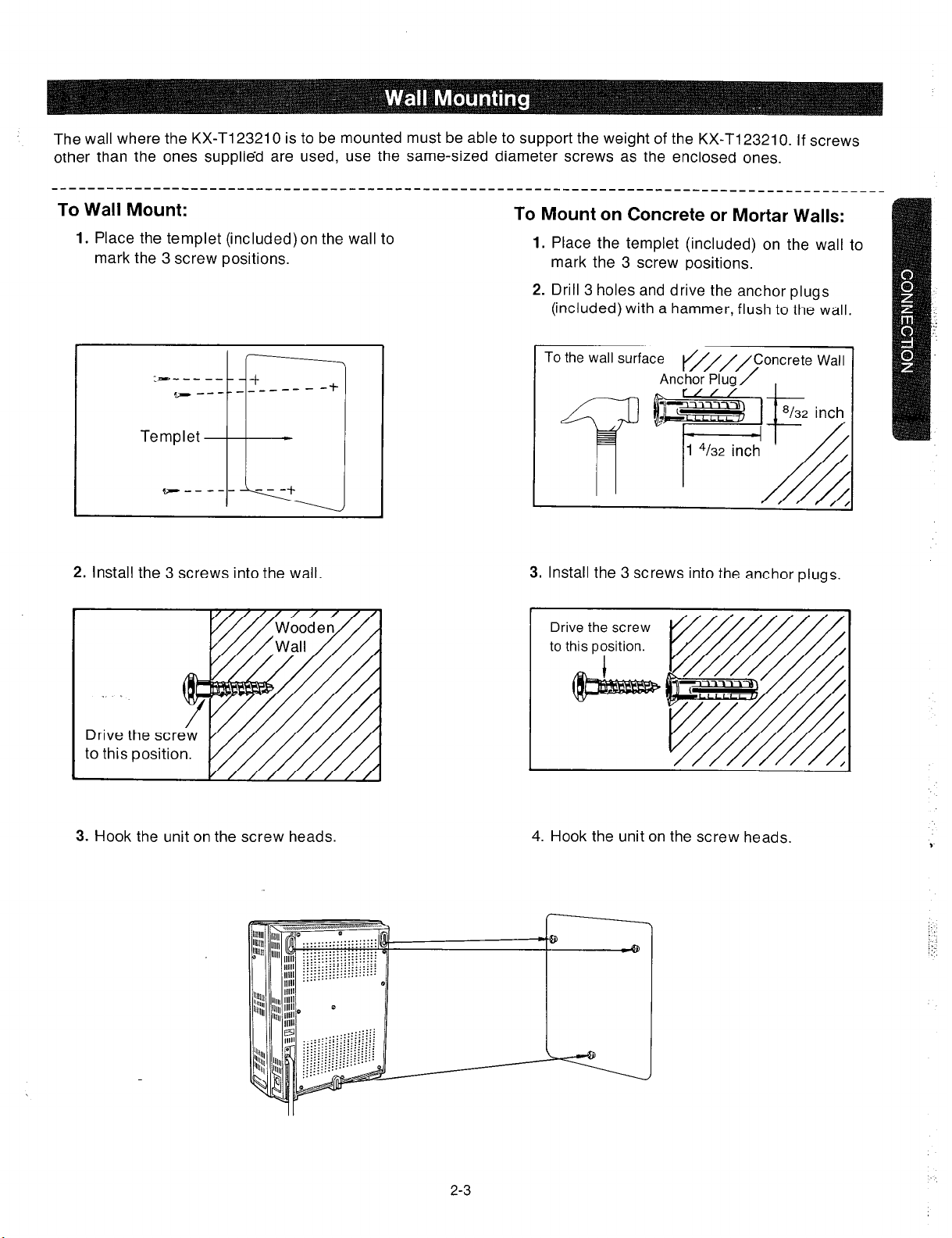
The wall where the KX-Tl23210 is to be mounted must be able to support the weight of the KX-Tl23210. If screws
other than the ones supplied are used, use the same-sized diameter screws as the enclosed ones.
To Wall Mount:
1.
Place the templet (included) on the wail to
mark the 3 screw positions.
:---_ __
2. Install the 3 screws into the wall.
To Mount on Concrete or Mortar Walls:
1.
Place the templet (included) on the wall to
mark the 3 screw positions.
2. Drill 3 holes and drive the anchor plugs
(included) with a hammer, flush to the wall.
To the wall surface
3. Install the 3 screws into the anchor plugs.
Drive the screw
to this position.
to this position.
y////////A
3. Hook the unit on the screw heads.
2-3
4. Hook the unit on the screw heads.
9
i:
i: :
::r,
Page 26

Unscrew the front cover of the unit.
1.
screws
There are four screws.
Open the front cover in the
2.
direction of arrow @
screws
=XI
When a power failure take place, there is no memory loss except for the camp-on, saved number redial,
the last number redial, Call park and Message waiting during power failure, memory is protected by 21 day
rechargeable battery.
1. Connect the battery (included) as shown
(Fig.1)
2. Install the battery into the battery
compartment. (Fig.2)
l
Replace the battery every 5 years
with (P-01 H-F2Gl). To remove
connector, depress the lock to release
and slide (pull) apart connector. (Fig3)
depress
Fig.1. 1
I
Fig.2
I
::.:
I
I
2-4
Fig.3
Page 27
CONNECTION
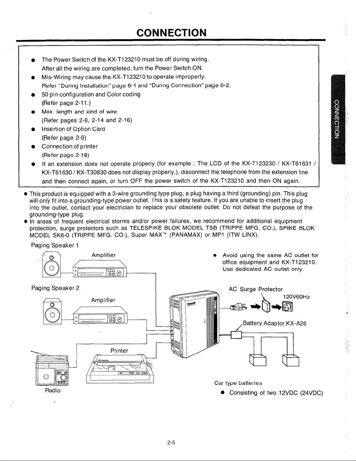
The Power Switch 07 the KX-T123210 must be off during wiring.
After all the wiring are completed, turn the Power Switch ON.
Mis-Wiring may cause the KX-Ti 23210 to operate improperly.
Refer “During Installation” page 6-l and “During Connection” page 6-2.
50 pin configuration and Color coding
(Refer page 2-l I.)
Max. length and kind of wire
(Refer pages 2-8, 2-14 and 2-16)
Insertion of Option Card
(Refer page 2-9)
Connection of printer
(Refer page 2-l 8)
If an extension does not operate properly (for example : The LCD of the KX-T123230 / KX-T61631 /
KX-T61630 / KX-T30830 does not display properly.), disconnect the telephone from the extension line
and then connect again, or turn OFF the power switch of the KX-T123210 and then ON again.
l
This product is equipped with a 3-wire grounding type plug, a plug having a third (grounding) pin. This plug
will only fit into a grounding-type power outlet. This is a safety feature. If you are unable to insert the plug
into the outlet, contact your electrician to replace your obsolete outlet. Do not defeat the purpose of the
grounding-type plug.
l
In areas of frequent electrical storms and/or power failures, we recommend for additional equipment
protection, surge protectors such as TELESPIKE BLOK MODEL TSB (TRIPPE MFG. CO.), SPIKE BLOK
MODEL SK6-0 (TRIPPE MFG. CO.), Super MAX’” (PANAMAX) or MPl (ITW LINX).
Paging Speaker 1
Paging Speaker 2
Radio
Printer
B
.I 0
A
m
l
Avoid using the same AC outlet for
office equipment and KX-T123210.
Use dedicated AC outlet only.
, .3 Surge Protector
Battery Adaptor KX-A26
Car type batteries
0 Consisting of two 12VDC (24VDC)
2-5
Page 28
1 KX-Ti 23240
-----------___
L___________________------~
Doorphone 2
------______-
KX-T61640
1
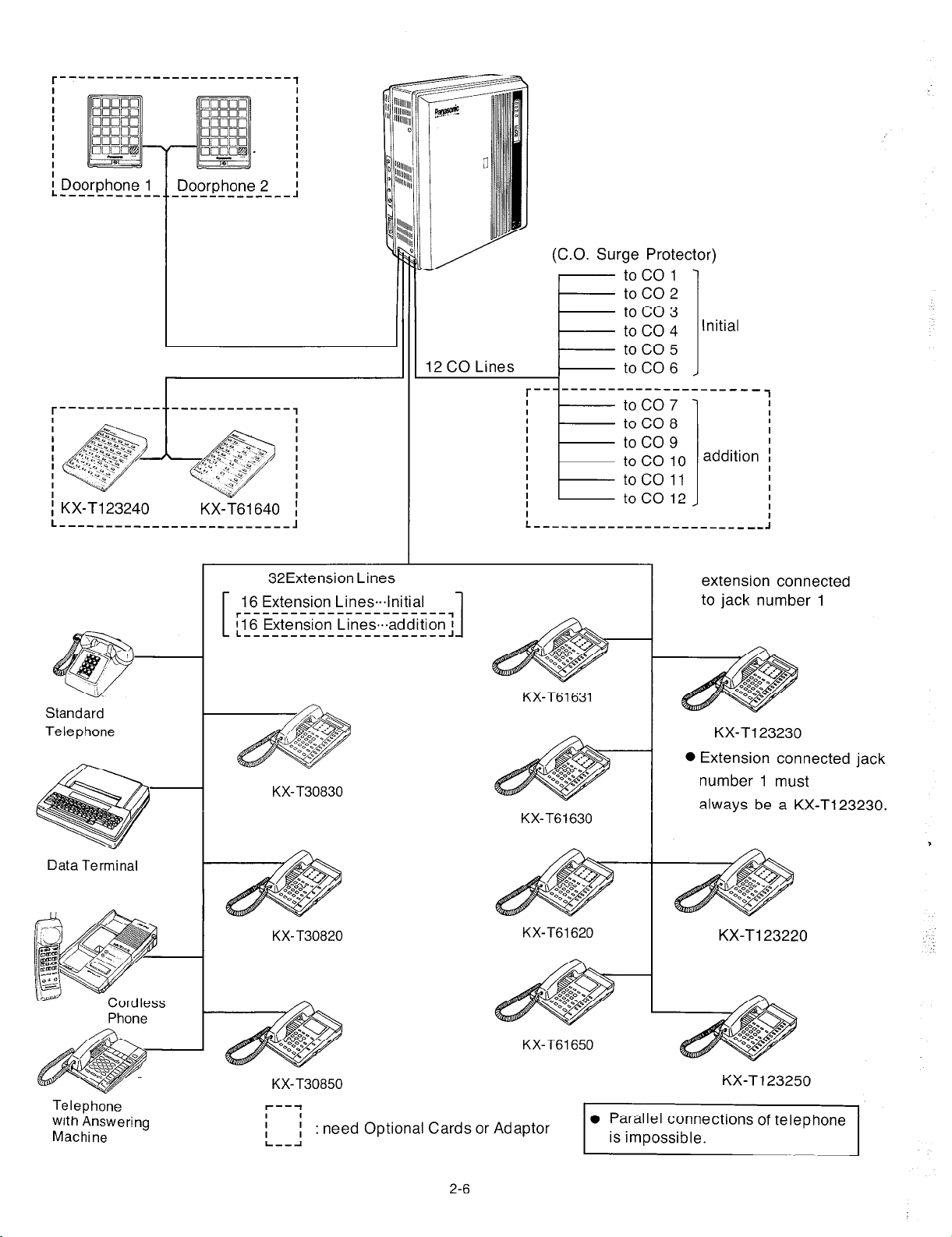
(C.O. Surge Protector)
toco1
toco2
toco3
toco4
toco5
12 CO Lines
;
toC06
toco7
toC08
toco9
to co 10
taco 11
to co 12
Initial
---___
addition I
1
I
I
I
I
I
Standard
Telephone
Data Terminal
Phone
32Extension Lines
r----------------------,
116 Extension Lines.addition
L----------------------J
KX-T30830
KX-T30820
1
1
KX-T61631
KX-T61630
KX-T61620
extension connected
to jack number 1 16 Extension Lines.lnitial
KX-Tl23230
0 Extension connected jack
number 1 must
always be a KX-T123230.
,
:
KX-T61650
KX-T30850
Telephone
with Answering
Machine
I
I
L--J
; :
need Optional Cards or Adaptor
2-6
0 Parallel connections of telephone
is impossible.
KX-T123250
Page 29
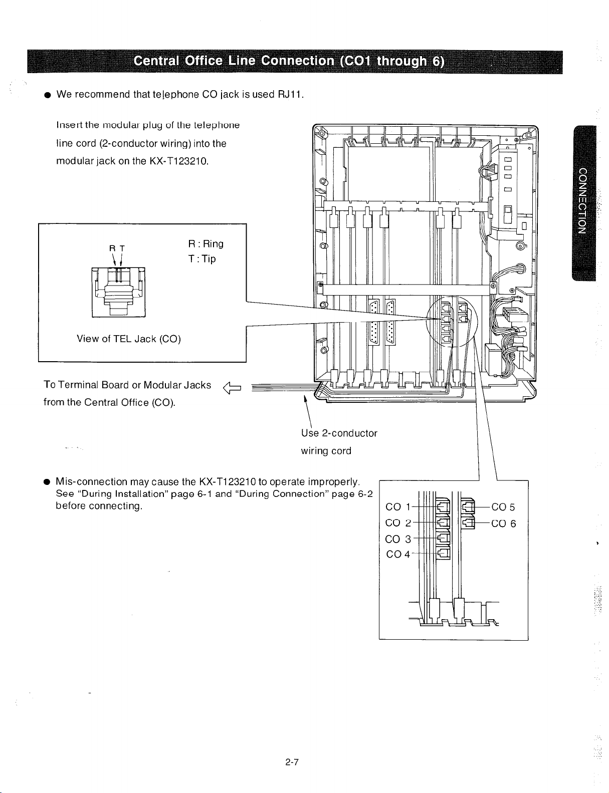
o We recommend that tejephone CO jack is used RJll.
insert the modular plug of the telephone
line cord (2-conductor wiring) into the
modular jack on the KX-T123210.
FIT
R : Ring
T : Tip
View of TEL Jack (CO)
To Terminal Board or Modular Jacks
+
from the Central Office (CO).
Use 2-conductor
.
wiring cord
0 Mis-connection may cause the KX-TI 23210 to operate improperly.
See “During Installation” page 6-l and “During Connection” page 6-2
before connecting.
2-7
,
‘.:.
:.:.
: .::
:_
)_ ‘1
Page 30
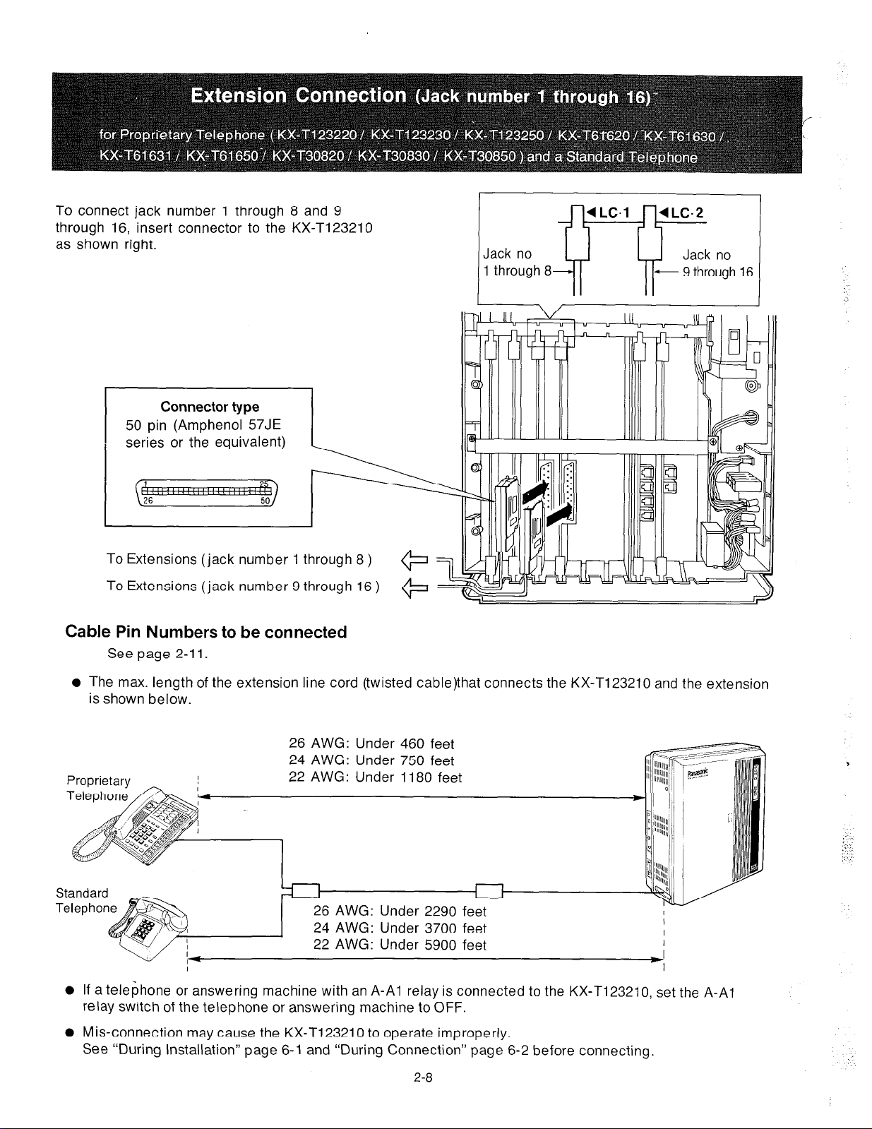
To connect jack number 1 through 8 and 9
through 16, insert connector to the KX-T123210
as shown right.
Connector type
50
pin (Amphenol 57JE
series or the equivalent)
To Extensions (jack number 1 through 8 )
To Extensions (jack number 9 through 16 )
Jack no
1 through 8
Cable Pin Numbers to be connected
See page 2-l 1.
l
The max. length of the extension line cord (twisted cable)that connects the KX-T123210 and the extension
is shown below.
26 AWG: Under 460 feet
24 AWG: Under 750 feet
22 AWG: Under 1180 feet
6 AWG: Under 2290 fe
4 AWG: Under 3700 fe
2 AWG: Under 5900 feet
I
0
If a telephone or answering machine with an A-Al relay is connected to the KX-T123210, set the A-Al
relay switch of the telephone or answering machine to OFF.
0
Mis-connection may cause the KX-T123210 to operate improperly.
See “During Installation” page 6-l and “During Connection” page 6-2 before connecting.
I
I
I
I
2-8
Page 31

1.
To protect the printed circuit board from static
electricity, first discharge any body static by
touching the metal board.
2. Loosen the screws to remove the metal board.
3. The location of the optional cards for the
KX-Tl23210 is shown in the following.
DSS Console
Card
(KX-Tl23241)
0 Insert the optional card with holding a
levers of the card into the KX-Tl23210
surely.
DO not touch parts on the card.
metal board
Expansion Card
KX-Tl23270
KX-T123271
I
--
Expansion Card
KX-T123270
KX-Tl23271
DSS Console
Card
KX-T1:3241
ii
/
Expansion Card
KX-Tl23280
KX-Tl23281
Screw
Optional Cards
Expansion Cards
DSS Console Card
I
Model No
KX-Tl23270
KX-Tl23271
KX-Tl23280
KX-Tl23281
KX-Tl23241
Description
This card adds 8 Extension’s
This card adds 4 Extension’s,
I
This card adds 4 CO’s.
This card adds 2 CO’s,
The DSS Console requires the DSS
Console Card for the operation.
2-9
Reference Page
2-10
I
2-14
Page 32

To add eight extensions (jack number 17 through
24), use the optional expansion card
KX-T123270.
To add four extensions (jack number 17 through
20), use the optional expansion card
KX-T123271.
1. Insert the expansion card KX-T123270 or
KX-Tl23271 into the KX-Tl23210.
2. Insert connector to the KX-T123270 or
KX-T123271 as shown at right.
Cable Pin Numbers to be connected
See page 2-l 1.
0 Mis-connection may cause the KX-T123210
to operate improperly.
See “During Installation” page 6-l and
“During Connection” page 6-2 before
connecting.
To Extensions (jack number 17 through 20,
or 17 through 24 )
@
Connector type
50
pin (Amphenol 57JE
series or the equivalent)
Expansion/card
KX-T123270 . jack number 17 through 24
KX-T123271 .
jack number 17 through 20
(
‘.
To add-eight extensions (jack number 25 through
32), use the optional expansion card
KX-Tl23270.
To add four extensions (jack number 25 through
28), use the optional expansion card
KX-Tl23271.
1.
Insert the expansion card KX-T123270 or
KX-Tl23271 into the KX-Tl23210.
2. Insert connector to the ‘KX-T123270 or
KX-T123271 as shown at right.
Cable Pin Numbers to be connected
See page 2-l 1.
l
Mis-connection may cause the KX-T123210 to
operate improperly.
See “During Installation” page 6-l and
“During Connection” page 6-2 before
connecting.
To Extensions (jack number 25 through 28,
or 25 through 32 )
2-10
Connector type
50
pin (Amphenol 57JE
series or the equivalent)
Expansion card
KX-T123270 . . jack number 25 through 32
KX-T123271 . jack number 25 through 28
Page 33

Cable Pin Numbers to be connected
l
Connection of the Proprietary Telephone
T:Tip
Dl :Datal
R:Ring D2:Data2
l
Connection of a Standard Telephone
Connect the only pin number of “T” and “R”.
1
CONN.
1
PIN
26
27
2
28
3
29
4
30
5
31
7 ORN-RED
33
a
34
9
35
H
10
’
36 BLK-BLU
11 BLU-BLK
37 BLK-ORN
12 ORN-BLK
38 BLK-GRN
13 GRN-BLK
39 BLK-BRN
14 BRN-BLK
40 BLK-SLT
15 SLT-BLK
41 YEL-BLU
16 BLU-YEL
42 YEL-ORN
17 ORN-YEL
43 YEL-GRN
ia
44 YEL-BRN
19 BRN-YEL
45 YEL-SLT
20 SLT-YEL
46 VIO-BLU
21
1
47
1
CABLE
COCOR
WHT-BLU
BLU-WHT
WHT-ORN
ORN-WHT
WHT-GRN
GRN-WHT
WHT-BRN
BRN-WHT
WHT-SLT
SLT-WHT
RED-BLU
RED-GRN
G RN-RED
RED-BRN
BRN-RED
RED-SLT
SLT-RED
GRN-YEL
BLU-VI0
VIO-ORN
CLIP
NO.
1
2
3
4
5
6
7
a
9
10
11
12
13
14
15
16
17
ia
19
20
21
22
23
24
25
26
27
28
29
30
31
32
33
34
35
36
37
38
39
40
41
42
43
44
45
46
47
48
49
50
LC-1 LC-2
T
JACK
No.1
JACK
No.2
JACK
No.3
JACK
No.4
JACK
No.5
R
Dl
D2
T
R
Dl
D2
T
R
Dl
D2
T
R
Dl
D2
T
R
Dl
D2
1
l-
T
1
JACK
No.6
JACK
No.7
JACK
No.8
R
Di
D2
R
Dl
D2
T
R R
Dl
D2
JACK
No.9
JACK
No.10
JACK
No.1 1
JACK
No.12
JACK
No.13
JACK
No.14
JACK
No.15
JACK
No.16
LC-3
T
R
JACK
Dl
D2
No.1 7
I-
T
R
Dl
JACK
D2
No.18
T T
R
JACK
Dl
D2
No.22
T
R R
Dl
JACK
D2
No.23
T
Dl
JACK
D2
No.24
LC-4
T
R
JACK
Dl
D2
No.25
I
T
1
R
Dl
JACK
D2
No.26
I
T
1
R
Dl
JACK
D2
No.27
T
R
’
Dl
JACK
D2
No.28
T
R
Dl
JACK
D2
No.29
t
R
JACK
Dl
D2
No.30
T
Dl
JACK
D2
No.31
-T-l--
R
Dl
JACK
D2
No.32
T
R
Dl
D2
T
R
Dl
02
T
R
Dl
D2
T
R
Dl
D2
T
R
Di
D2
T
R
Dl
D2
T
R
Dl
D2
T
R
Dl
D2
Station wiring (2-pair twisted cabling):
Connector Block
27
2
28
Bridging Clips
Modular Jack
Line code
2-11
Page 34

To add four Central Office Lines (CO 9
through 12), use the optional expansion
card KX-T123280.
1.
Insert the expansion card KX-T123280 into
the KX-Tl23210.
2.
Insert the modular plug of the telephone
line cord (2-conductor wiring) into the
modular jack on the KX-T123280.
0
Mis-connection may cause the KX-Tl23210
to operate improperly.
See “During Installation” page 6-l and
“During Connection” page 6-2 before
connecting.
To Terminal Board or Modular Jacks
Vi
RT
R : Ring
T : Tip
ack (CO)
09
010
011
from the Central Office (CO).
To add two Central Office lines (CO9 and
COlO), use the optional expansion card
KX-Tl23281.
1.
Insert the expansion card KX-T123281
into the KX-Tl23210.
2.
Insert the modular plug of the telephone
line cord (2-conductor wiring) into the
modular jack on the KX-T123281.
0
Mis-connection may cause the KX-T123210
to operate improperly.
See “During Installation” page 6-l and
“During Connection” page 6-2 before
connecting.
Use 2-conductor wiring cord
R : Ring
T : Tip
View of TEL Jack (CO)
To Terminal Board or Modular Jacks
from the Central Office (CO).
e
Use
2-conductor
2-l 2
(KX-Tl23281)
wiring cord
Page 35

To add two Central Office lines (CO7 and 8),
use the optional expansion card KX-T123280.
Remove the card which is inserted into
groove marked “C0.2”.
Insert the expansion card KX-T123280 into
the KX-T123210.
Insert the modular plug of the telephone
line cord (2-conductor wiring) into the
modular jack on the KX-T123280.
l
Mis-connection may cause the KX-T123210
to operate improperly.
See “During Installation” page 6-l and
“During Connection” page 6-2 before
connecting.
To Terminal Board or Modular Jacks
from the Central Office (CO).
RT
View of TEL Jack (CO)
*
\
Use 2-conductor wiring cord
R : Ring
T :Tip
co5
CO6
co7
CO8
Page 36

To connect the optional DSS Console (KX-Tl23240 or KX-T61640), the optional DSS Console card (KX-T123241)
is required.
The DSS Console (KX-T123240 or KX-T61640) needs a paired Telephone (EMSS Proprietary Telephone) for
proper operation, because the DSS console cannot work by itself.
The EMSS Proprietary Telephone (such as KX-Tl23220, KX-Tl23230, KX-T123250, KX-T6I 620, KX-T61631,
KX-T61630, KX-T61650, KX-T30820, KX-T30830, KX-T30850) is required as the paired telephone for dialing,
storing, etc.
Place the KX-T123240 or KX-T61640 and the paired telephone side by side on your desk.
1.
Insert the DSS Console card (KX-T123241) into the
KX-Tl23210.
2. Insert the modular plug of the console line cord
(4-conductor wiring) into the modular jack on the
KX-Tl23241.
DSS Console Card
KX-T123241
Console 1
Console 2
b
View of TEL Jack
Notes:
Up to 2 KX-T123240’s or KX-T6164O’s can be connected
to the KX-T123210. Each console requires its own
paired telephone.
KX-Tl23240 or KX-T61640 can not be connected in
pair with a standard telephone.
The max. length of the console line cord (twisted
cable) that connects the KX-Tl23210 and the DSS
Console is shown below.
AWG:
AWG:
Under 460 feet
Under 750 feet
Under
1180
feet
26
24
22 AWG:
Pair Telephone
(EMSS Proprietary
Telephone)
I
4-conductor wiring is
required for the
DSS Console
DSS Console
KX-Tl23240
KX-T61640
I
Pair
When using the KX-T123240 or KX-T61640, program
must be done. Refer to “Paired Telephone Assignment
for DSS Console” page 3-10.
2-14
Page 37

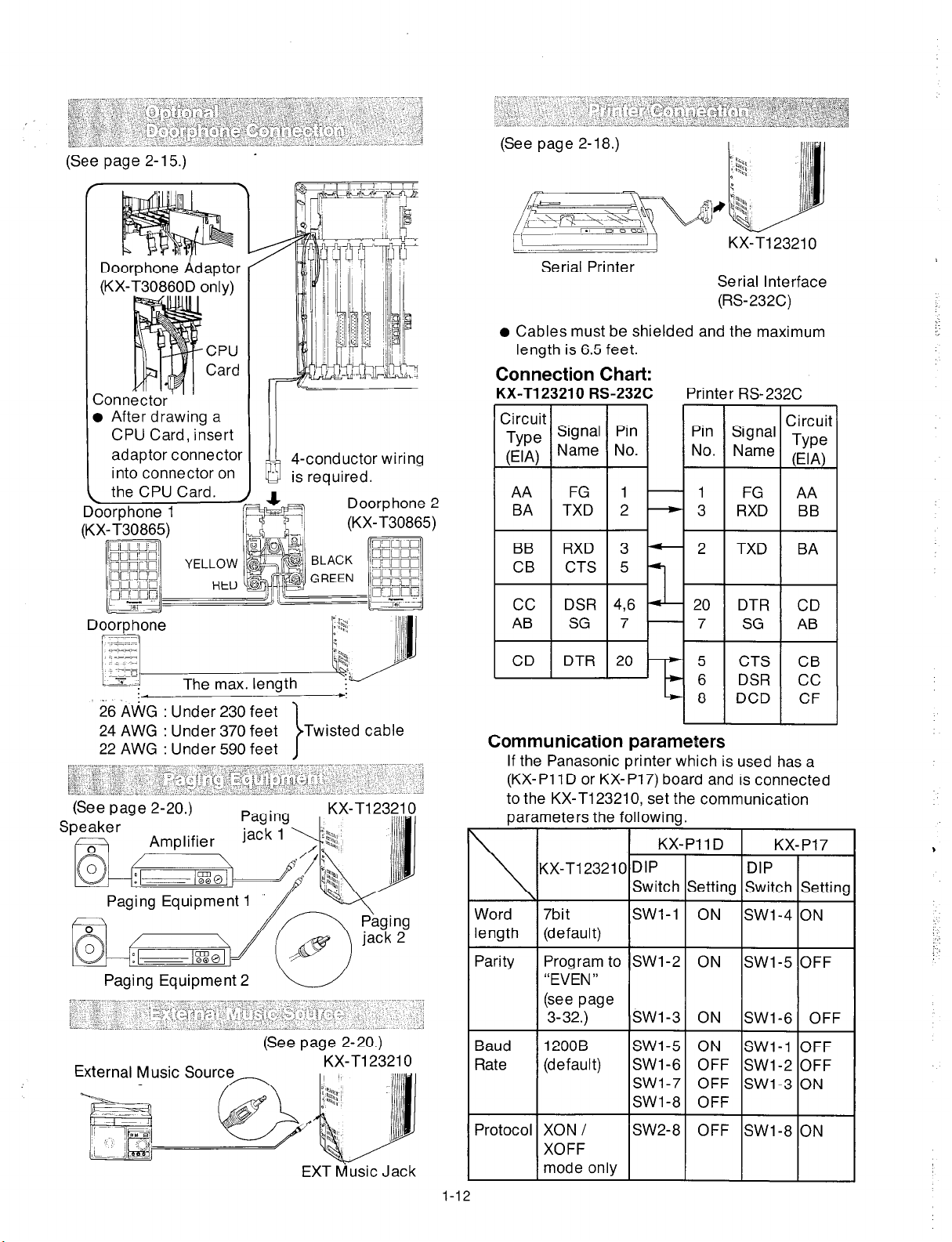
For installing the doorphone, use the Optional Doorphone
Adaptor (Use the KX-T30860D only).
Installation of the doorphone
Loosen the screw to
separate the
doorphone into 2
halves.
install the lower case
to the wall with 2
screws.
l
2 Kinds of screws
are included. Please
choose according to
your wall type. See
the followings.
@m-----When the doorphone plate has
been fixed to the wall.
w-------When you wish to install the
doorphone directly to the wall.
3. Connect the wires
from the terminal
box to the screws
located in the
upper case.
Installation of the Doorphone Adaptor
How to install the Doorphone Adaptor into the
KX-Tl23210.
1.
Connect a 4-conductor modular connector to
the doorphone adaptor.
doorphone adaptor (KX-T30860D)
I
:
2. Install the doorphone adaptor into the
adaptor compartment.
4-conductor wiring
to the terminal box
c
(See page 2-16)
4. Secure both halves together and re-install the
screw.
,
3. After drawing a CPU Card, insert the adaptor
connector into connector on the CPU Card
(circuit board).
Adaptor Connector
Connector CPU Card
2-15
Page 38

Doorphone Wiring
(A) Connect the doorphohe adaptor to the terminal box using a 4-conductor modular connector.
(B) Connect the wires of doorphone 1 to the red and green screws of the terminal box.
(C) Connect the wires of doorphone 2 to the yellow and black screws of the terminal box.
Doorphone Adaptor
(KX-T30860D only)-
ty_
-4-conductor wiring
is required.
a
%
Terminal
Doorp hone
e The max. length of the telephone line cord (twisted cable) that connects the KX-T123210 and the doorphone
(KX-T30865) is shown below.
1 (KX-T30865)
26 AWG: Under
24 AWG: Under
22 AWG: Under
230 feet
370 feet
590 feet
Doorphone 2 (KX-T30865)
t
2-16
Page 39

If the telephone you are using with the KX-Tl23210 is polarity sensitive.
1. Connect all extension wiring to the KX-Tl23210
2. Confirm that dialing can be done from all the
extensions using a tone telephone.
3. If a dialing can not be done, the polarity between
the extension and the KX-Tl23210 must be
reversed.
KX-Tl23210
Central Office Line
6. Confirm that dialing can be done on the
following extensions using a tone telephone.
Extension of jack number l--CO1
Extension of jack number 2--CO2
Extension of jack number g--CO.5
Extension of jack number lo--CO6
Extension of jack number 17--CO9
Extension of jack number 18--CO10
7. If dialing can not be done, the polarity between
the KX-Tl23210 and the Central Office Line must
be reversed.
KX-Tl23210
Central Office Line
4. Set the Power Switch on the KX-Tl23210 to the
OFF-position.
8. If any extension is changed or replaced, repeat
these procedures (from step 1 through step 7).
5. Connect all Central Office (CO) Lines.
Car type batteries which are customer supplied is available as a back up power supply to the KX-Tl23210
to operator all the features in the event of power failure.
For connecting car type batteries, use the Optional Battery Adaptor KX-A26.
1.
Connect the Battery Adaptor KX-A26 to car type batteries.
2. Connect the Battery Adaptor KX-A26 to the Battery Backup Connector of the KX-Tl23210.
KX-Tl23210
Car type batteries
0 Consisting of two 12 VDC (24 VDC)
Backup Connector
ttery
o 16 amp / hour maximum rating
2-17
Page 40

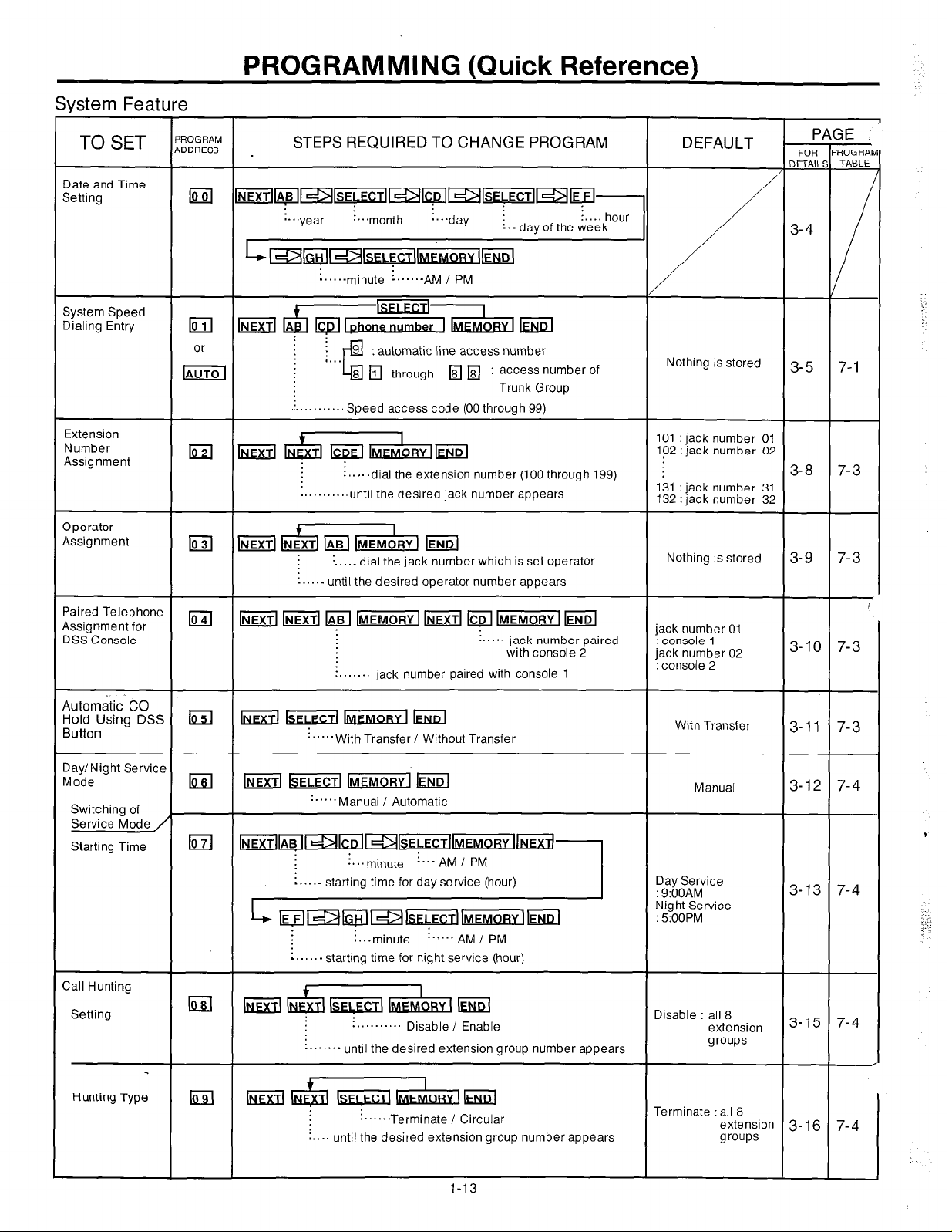
Serial Prihter
Make cables so that the printer will be connected
to the KX-Tl23210 as shown in the chart.
Cables must be shielded and the maximum length
is 6.5 feet.
Connection Chart
:
KX-T123210 RS-232C Printer RS-232C
Serial Interface
( RS-232C )
When using special accessories such as cable, the
user should use those specified in this installation
manual to comply with the limits for a Class A
computing device pursuant to Subpart J of Part 15
of FCC Rules.
The pin configuration of EIA (RS-232C) connector is
as follows.
Pin
Number
1
2
Signal Name
FG Frame Ground
TXD Transmitted
Circuit Type
EIA CCITT
AA
BA
101
103
Data
I
0 Panasonic data terminal
;
KX-D4910D, KX-D4911, KX-D4920, KX-D4985, etc.
If you connect this unit to a Panasonic Data
Terminal, the Communication Parameter
Transmit XON / XOFF on the Data Terminal must
be set to the “YES” position.
For further details, see the Operating
Instructions of the Data Terminal.
2-18
4
20
3
RXD Received
RTS Request To
Data BB
CA 105
104
Send
CTS Clear To Send
DSR DataSet Ready
SG Signal Ground
DCD Data Carrier
CB 106
CC 107
AB 102
CF 109
Detect
DTR DataTerminal CD
108.2
Ready
Page 41

EIA SIGNALS:
Frame Ground (FG);
Connects to the unit frame and the earth ground
conductor of the AC power cord.
Data Set Ready
(DSR);.......................(input)
An On condition of circuit DSR indicates the
printer is ready. Circuit DSR ON does not indicate
that communication has been established with
the printer.
Transmitted Data
Conveys signals from the unit to the printer. A
“Mark” condition is held unless data or BREAK
signals are being transmitted.
Received Data (R)(D);. . . . . . . . . . . . . . . . . . . . . . .
Conveys signals from the printer.
Request To Send
This lead is held ON whenever DSR is ON.
Clear To Send (CTS);.....................
An ON condition of circuit CTS indicates that the
printer is ready to receive data from the unit. The
unit dose not attempt to transfer data or receive
(TXD);..................(output)
(RTS);...................(output)
.(input)
..(input)
Signal Ground (SG);
Connects to the DC ground of the unit for all
interface signal.
Data Terminal Ready
(DTR)...............(output)
This signal line is turned ON by the unit to indicate
that it is ON LINE. Circuit DTR ON does not
indicate that communication has been
established with the printer. It is switched OFF
when the unit is OFF LINE.
Data Carrier Detect
(DCD)..................(input)
The ON condition is an indication to data terminal
(DTE) that the carrier signal is being received.
data when circuit CTS is OFF.
1.
If the Panasonic printer which is used has a (KX-PI 1D or KX-P17) board and is connected to the
KX-T123210, set the communication parameters below.
KX-Pll D
KX- P17
KX-T123210
Word length
Parity
Baud Rate
Protocol
7 bit (default)
Program to “EVEN”
(See page 3-32)
12008 (default)
XON / XOFF mode
only
DIP switch
Setting
SWl-1
SWl-2
SWl-3
SWl-5
SWl-6 OFF
SWl-7 OFF
SWl-8
SW2-8
DIP switch
ON
ON
ON
ON
SWl-4
SWl-5
SWl-6
SWl-1
SWl-2
OFF
SWl-3
OFF SWl-8
Setting
ON
OFF
OFF
OFF
OFF
ON
ON
2. If the Panasonic data terminal is a KX-D4985 or KX-D4920 and is connected to the KX-Tl23210, the default
value of communication parameter is the same as that of the KX-Tl23210.
If the KX-D4910D is connected to the KX-T123210, set the baud rate of the KX-D4910D to 1200 baud, the
other default value is the same as that of the KX-T123210.
,
2-19
Page 42

Speaker
;plrrr
Speaker
/ \
Amplifier
Paging equipment 1
Paging equipment 2
Use an RCA connector.
l
Output impedance:
6OOfl
Use shielded cable.
Paging jack 1
l
Pa\ging jack 2
Use a two-
conductor plug
(9/64 inch in diameter)
l
Input impedance
5kfl
0 Input Level
-1OdBm
Please use a
cord that has
“‘I ~llllllll~~,
‘I” ~lllllll1l~,
‘I” llllllllllll
0
0
!!!!!~llll1
‘I
EXT MUSIC Jack
-
11111l
. . .
2-20
Page 43

PROGRAMMING
To activate this system, the requirements from telephone company and the customer must be programmed once
the Power Switch has been turned on.
1.
At extension connected to jack number 01: All system
programming changes (example : system clear,
toll restriction, system speed dialing entry...) are
done through extension connected to jack
number 01.
l
Extension connected to jack number 01 must
always be a Panasonic model, KX-Tl23230.
2. System Program Switch setting:
The System Program Switch located on the
KX-T123210 must be set to the “PITS”
(Proprietary Integrated Telephone System)
position while making program changes. After
all programming changes are completed, return
the program switch to the “SET” position.
4.
Press the MEMORY button to clear system.
To return to the initial program mode, press the
5.
END button.
0 The following parameters are preset as the default
data.
System parameters
CO parameters
Extension parameters
DSS parameters
Speed call
3. Overlay:
This overlay is used for programming the
system and the program function names are
inscribed on this card, Refer to page 3-2.
4. Before system programming, operate the
system clear to set to the default data of the
program. See page 3-78.
System Clear:
Set the System Program Switch of the
KX-T123210 to the “PITS” position.
Dial (99).
“System Clear” will be displayed.
Press the NEXT button.
Repeat pressing the SELECT button until the
“Menu: All Para” is displayed.
3-l
,
:, ..:
j::..
Page 44

When the System Program Switch on the KX-T123210 is set to the “PITS” position, the operation of the
KX-T123230 connected to jack number 01 will change as follows.
CLEAR button
PAUSE button
button
+
I
PROGRAMMABLE
FEATURE button
Overlay
\
button
+
I---
- LIQUID CRYSTAL
Display (LCD)
PREVIOUS button
FLASH button
CENTRAL OFFICE (CO)
AUTO/M EMORY button
SELECT button
ICM (SECRET) button
3-2
Page 45

1.
Turn the Power Switch to ON.
2. Set the System Program Switch to “PITS” position.
The LCD on the KX-T123230 will show “SYS-PGM NO ?-I’.
o Be sure the handset of the extension connected to jack number
01 is in the cradle and the speakerphone button off.
3. To program automatic line access number 9 and the phone
number 987-654-3210 into speed access code 00. (Refer to
page 3-5.)
KX-Tl23230 at extension connected to jack number 01.
(Extension connected to jack number 01 must be a
1
KX-T123230.1
Dial (01) or press the
Display
Auto button.
2
-
Press the NEXT button.
3
Dial (00) or press the
NEXT button.
l
If nothing is stored in
access code “OO”,
00: Not Stored
l
If already stored the
automatic line access
number 9 and the phone
number 123-456-7890,
4
0 Dial “9”.
@ Press “ - ” button.
While programming if a mistake is made,
0 Dial “987”.
@ Press “ - ” button.
1. Press the “END” button.
($ Dial “654”.
@ Press “ - ” button.
-
-
0 Dial “3210”.
Press the MEMORY
5
button.
l
To program the next access code, press the NEXT
6
2. Start programming procedure from the
beginning.
l
You will hear a beep after pressing the
MEMORY button.
button.
l
l
To program a desired access code, press the SELECT
7
-
button and dial speed access code.
The MEMORY indicator light will go on
when the MEMORY button is pressed,
and then the Indicator light will go out
when the NEXT or PREV button is pressed.
8
4. Return the System Program Switch to “SET” position.
0 To make program change, start from the beginning.
3-3
Page 46

System Feature
: . . . . . . . . . . . . . .
‘. . . . . . . . . . . . . . . . . . . . . . . . . . . . . . . . . . . . . . . . . . . . . . . . . . . . . . . . . . . . . . . . . . . .._
I . . .._. _ . . . . . . . . . . . . . . . . . . . . . . . . . . . . . . . . . . . . . . . . . . . . . . . . . . . . . . . . . .
Description
Entry of the current day, date and time.
~...............................................
_...........................-
i”“‘.“’ enter the hour with 1 or 2 digits
: :““- enter the minutes with 2 digits
: :
:
: :
: :
: : :
: : ,........................._
: :
7. Press the m button. “12:OO AM” will be
8. Enter the hour with 1 or 2 digits.
enter
18)k/
until the
the year
:1987 year
desired
with 2 digits.
month
is
displayed
enter the day with 1 or 2 digits
until the desired day of the
week is displayed
i ;.- until the desired AM/PM is
: :
: displayed
. . . . . . . . . . _
-
displayed.
i
Programming
1.
Dial(OO).
“Day/Time Set” will be displayed.
2.
Press the NEXT button.
“87Jan.l THU” will be displayed and “87”
will blink.
3.
Enter the year (last 2 digits) using the dialing
button.
4.
Press the m button and then repeat
pressing the SELECT button until the desired
montn Is arsprayea.
5.
Press the @ button and then enter the day
with 1 or 2 digits.
6.
Press the m button and then repeat
pressing the SELECT button until the desired
day of the week is displayed.
3-4
9. Press the m button and then enter the
minute with 2 digits.
10.
Press the m button and then repeat
pressing the SELECT button until the desired
AM/PM is displayed.
11.
Press the MEMORY button.
12.
To return to the initial program mode, press
the END button.
Con1 dition
If m button is pressed, the display will
0
return to the previous sequence in the
programming step.
Instantly after pressing the MEMORY button,
0
the new time will start.
However, the LCD of extension connected to
jack number 01 will display the new time only
after the System Program Switch is set to
“SET”.
Page 47

_........................................
AB=mk[ : speed access code 00
F[k[ : speed access code 99
: automatic line access number
= access number of Trunk Group1
m%i : access number of Trunk Group8
or
,.................
until the desired speed access code (00 through 99) appears
lmm(INEXTImIphone number IIMEMoRV(EI
Description
100 system phone numbers can be stored with
each number capable of storing 32 digits and
may be accessed from any extension.
Pushing the “ ++‘I, ‘I#” “PAUSE”, “-‘I,
“FLASH” or “ICM (Secret)” button counts as 1
digit.
Refecto “Speed Dialing” on page 4-3.
Programming
1. Dial (01) or press the AUTO button.
“Speed Dialing” will be displayed.
2. Press the NEXT button.
“Speed NO?-”
3. Dial (00 through 99) or press the NEXT
button, for speed access code entry.
Example
When dialing (00) or pressing the NEXT
button.
l
The LCD will show “00:Not Stored” when
nothing is stored in speed access code
“00”. When the automatic line access
number 9 and the phone number
123 - 456 - 7890 are stored,
“Oq: 9- 123- 456- 789” will be displayed.
will be displayed.
:
4. Enter automatic line access number or trunk
group number.
See page 4-2, regarding automatic selection.
See page 3-46 and 4-3, regarding trunk group.
9 : automatic line access number
81 : access number of trunk group 1
82 : access number of trunk group 2
83 : access number of trunk group 3
84 : access number of trunk group 4
85 : access number of trunk group 5
86 : access number of trunk group 6
87 : access number of trunk group 7
88 : access number of trunk group 8
5. Enter the phone number.
l
You may enter punctuations during a phone
number.
l
To erase a wrong entry, press the CLEAR
button.
When you don’t want to display the dialed phone
number on the LCD in speed dialing, press the ICM
(SECRET) button before and after dialing the phone
number that you want to keep secret. Do not press
the ICM button before line access number (9 or 81
through 88) and account code.
Example:
press the ICM button
The display shows as follows when
01 : 9-123 [456]
The display shows as follows when dialing.
-123---
1
programming.
3-5
Page 48

6. Press the MEMORY button.
l
The memory indicator will be lit.
7. l To advance to the next speed access code,
press the NEXT button.
l
To return to the previous speed access
code, press the PREV button.
l
To go to the desired speed access code,
press the SELECT button and then dial the
speed access code.
8. Repeat steps 4 to 7, to program the other
phone numbers.
9. To return to the initial program mode, press
the END button.
Conditions
Use the “ +“, or “ +” button for scrolling
the display.
Automatic line access number 9 or trunk
group access number (81 through 88)
should be stored.
When dialing, the pause is automatically
entered after automatic line access number 9
or trunk group access number (81 through
88) has been dialing.
Continuous use of speed dialing is possible.
Example :
To change
Repeat steps 1 to 9.
To erase after programming
1. Dial (01) or press the AUTO button.
“Speed Dialing” will be displayed.
2. Press the NEXT button.
“Speed NO ?
+I’
will be displayed.
3. Dial (00 through 99 )or press the NEXT
button, for speed access code entry.
The speed access code and the phone
number will be displayed.
4. Press the CLEAR button.
5. Press the MEMORY button.
6. l To advance to the next speed access code,
press the NEXT button.
l
To return to the previous speed access
code, press the PREV button.
l
To go to the desired speed access code,
press the SELECT button and then dial the
speed access code:
In this case, speed access code “02” should
not include the automatic line access number
or trunk group access number.
When dialing, the dialed number will be
displayed on the LCD of the KX-T123230 /
KX-T61631 / KX-T61630 / KX-T30830.
The limit of the LCD is 16 characters but
will scroll all numbers stored.
To erase all entries, refer to “System Data
Clear” on page 3-78.
There is a blank phone number directory on
page 7-l.
7. Repeat steps 4 to 6, to erase the programmed
other phone number.
8. To return to the initial program mode, press
the END button.
Page 49

’ Examples
1) To enter trunk group access number 81 and telephone number 201-392-4669 into speed access code 00.
(01 NEXT008; 201-392-4669MEMORYw
Speed access i Telephone
code
number
Trunk’group
access number
l
If punctuation is not entered in a phone number, the LCD will show as below.
( 00 : 812013924669 )
2)
To enter automatic line access number 9, account code 1234 and telephone number 201-392-4669 into
speed access code 02.
l
(01 NEXT02 9 * * 1234201-392-4669 MEMORY END)
--- 7
Speed access!
code
: :
Telephone number
account code
Refer to “Account code Input mode” page
3-70 and “Account code” page 4-39.
automatic line
access number
3)To access MCI
(01 NEXT 01 9 123-4567 PAUSE PAUSE 9876 201-348-7000 MEMORY END)
-- TT
Speed access :
code
i MCI number i
automatic line
--v
. . . . . . . .
PAUSE button
Security Telephone
code
number
access number
‘.:
:.-.
:.
:. :
‘:_
4) To access ITT
(01 NEXT 02 81 765-4321 PAUSE PAUSE
--T 7 -Speed access i :
code
: ITTnumber i
,...._...... .
PAUSE button number
201-348-7000
Telephone
6789 MEMORY END)
Security
code
Trunk group access number
When required to change the dialing mode from the pulse mode to the tone mode. (See page 4-45)
pulse mode
F
Y
(01 NEXT 02 82 76543213~
ti PAUSE PAUSE ‘201-348-7000 6789 MEMORY END)
__-
tone mode
b
: # button
*button
3-7
r,
:’
. . .
Page 50

l...................until the desired Jack number (01 through 32) appears
~.......,.......................
,......._.__.................................
Description
Enables programming of a 3-digit extension
number (100 through 199) for each extension
phone. This provides the freedom to develop a
logical extension numbering system by
department or by building floor as desired.
Programming
1.
Dial (02).
“Extension NO Set” will be displayed.
2. Press the NEXT button.
“Jack NO ?+” will be displayed.
3. Press the NEXT button or dial the Jack
number (01 through 32 ).
“Jack 01 : EXTlOl” will, be displayed and
“101 “will blink.
4. Dial the extension number which is set
newly ( 100 throug h199 ).
l
When dialing (150), the LCD will show
“Jack 01 : EXTl.50” will be displayed.
l
To erase a wrong entry, press the CLEAR
button.
5. Press the MEMORY button.
6.
l
To advance to the next jack number, press
the NEXT button.
To return to the previous jack number,
0
press the PREV button.
To go to the desired jack number, press
0
the SELECT button and then dial the jack
number.
CDE=rI(OI(OI :
to assign phone number 100
111191191: to assign phone number 199
default
is assigned to extension of Jack number 01
132
is assigned to extension of Jack number 32
AB=mm
: to assign to Jack number 01
I*\ : to assign to Jack number 32
7. Repeat steps 4 to 6, to program the extension
number on the other jack number.
8. To return to the initial program mode, press
the END button.
o The LCD will show the initial program
mode, “SYS-PGM NO ? +“.
Conditions
l
The extension number has been already
programmed can not be entered.
In case programmed extension number is the
same as what was previously stored, when the
MEMORY button is pressed, three beeps will
be heard.
l
When the extension number 125 have been
already assigned to the jack number 25, for
programming to assign the extension number
125 to the jack number 02, after
programming to assign the other extension
number (100 through 199) to the jack number
25, program to assign the extension number
125 to the jack number 02.
Example:
Jack number 15
Jack number 30 . . . . . . . ..Extension number 180
~0211NEXT111511~
pj-liGlrMEMORYI1ENDI
Programming Table
See page 7-3.
3-8
. . . . . . . ..Extension number 170
Page 51

Page 52

Page 53

until the desired mode appears
!
:‘.
:.’
Description
Outside calls can be transferred to any
extension manually.
l
While an extension paired with the DSS
Console having a conversation with outside
calls, “With Transfer” mode allows you to
transfer outside call by only pressing the DSS
button of the DSS Console.
l
While an extension paired with the DSS Console
having a conversation with outside calls, “Without
Transfer” mode allows you to transfer outside call
by pressing the TRANSFER button and then DSS
button of the DSS Console. .
Programming
1. Dial (05).
Programming Table
See page 7-3.
“DSS Mode” will be displayed.
2. Press the NEXT button.
“With Transfer” will be displayed and blink.
3. Repeat pressing the SELECT button to alternate
between “With Transfer” and “Without
Transfer” to select the desired mode.
4. Press the MEMORY button.
The LCD will stop blinking.
5. To return to the initial program mode,
press the END button.
3-11
Page 54

_ .......................... until the desired mode appears
Man ......... Day/Night service is manually switched
Auto ......... Day/Night service is automatically switched
.......
default
Description
Allows Day/ Night service to be selected
manually or automatically.
In case of manual switching, refer to “Flexible
Night Service” on page 4-37.
In case of automatic switching, set the “Starting
Time (Day/Night Service mode)” on page 3-13.
The following features will be switched
Day mode or Night mode.
l
“Flexible Outward Dialing Assignment” on
page 3-47.
l
“Flexible Ringing Assignment”
on page 3-49.
l
“Delayed Ringing Assignment” on page 3-52.
l
“CO Direct In Line Assignment” on page 3-54.
l
“Service Class Assignment of Toll Restriction”
on page 3-64.
0 “Ringing Assignment from Doorphone” on
page 3-75.
Programming
1.
Dial (06).
“Day/Night Mode” will be displayed.
2. Press the NEXT button.
“Mode Change : Man” will be displayed
and “Man” will blink.
3. Press the SELECT button to alternate
between “Man” and “Auto” to select the
desired mode.
4. Press the MEMORY button.
The LCD will stop blinking.
5. To return to the initial program mode, press
the END button.
Conditions
When the Switching of Service Mode (Day/Night
Service Mode) is set to“Auto”, the present
Day/ Night Service mode will not change after
you finish programming.To change the present
mode,manual operation is required. After you
selected the Starting time (Day/ Night Service
Mode)page3_13,select the present Day/Night
mode by“Flexible Night Service” on page 4-37.
3-12
Programming Table
See
page 7-4.
Page 55

AB= 111
: to start at 1 o’clock for day service
191 : to start at 9 o’clock for day service . . . . . . . ..default
p$!-j : to start at 12 o’clock for day service
L
. . . . . . . . . . . . . . . . . . . . . . . . . . . . . . . .
:....“““.‘. until the desired mode awears
: f i f.’ until the desired mode appears
: :
: :
: :
: :
. 1 : :
: :
: : :
: : :
: :
I................................................................
: :
: i
: :
: : :
_.................................................
:
: :
CD=m,E[ : to start at 0 rninute.........................default
jT/i-Gl : to start at 59 minutes
AM . . . . . .
. . . . . . . . . . . . . . . . . . .
iifaul*
PM
EF= m
: to start at 1 o’clock for night service
m : to start at 5 o’clock for night service.........default
r\E] : to start at 12 o’clock for night service
GH =jaki : to start at 0 minute.
5 9 : to start at 59 minutes
ucl
. . . .._....I...,......... default
PM . . . . . . . . . . . . . . . . . . . . . . . . . default
AM
[
3-13
Page 56

Description
Conditions
If you select the automatic switching mode for
day/night service, enter the starting time.
Refer to “Switching of Service Mode (Day/Night
Service Mode)” on page 3-12.
Programming
1.
Dial (07).
“Day/Night Time” will be displayed.
2. Press the NEXT button.
“Day: 9:00 AM” will be displayed as a default
value and “9” will blink.
3. Enter the starting time for day service using 1
or 2 digits.
4. Press the “ +” button
“00” will blink.
5. Enter the minutes using 2 digits.
6. Press the “ q” button.
“AM” will blink.
7. Press the SELECT button to alternate between
“AM” and “PM” to select the correct setting.
If the NEXT button is pressed at step 3
through 7, the display will advance to the
“Night Time input” mode (step 9). The
operations of step 3 through 7 will not be stored.
If the PREV button is pressed at step 10
through 14, the display will return to the “day
time input” mode (step 2).The operations of
step 10 through 14 will not be stored.
Example:
8:30
6:30 PM
+tarting time for day plan
AM
.starting time for night plan
Programming Table
See page
7-4.
8. Press the MEMORY button.
The LCD will stop blinking.
9. Press the NEXT button.
“Night : 5:00 PM” will be displayed as a
default value and “5” will blink.
10.
Enter the starting time for night service using
1 or 2 digits.
11.
Press the ‘i 4” button.
“00” will blink.
12.
Enter the minutes using 2 digits.
13. Press the ‘I q” button.
“PM” will blink.
14.
Press the SELECT button to alternate between
“AM” and “PM” to select the correct setting.
15. Press the MEMORY button.
The LCD will stop blinking.
16. To return to the initial program mode, press
the END button.
: -..
3-14
Page 57

i,.......................-until the desired extension group number (1 through 8) appears
until the desired mode appears
i ~............................~
j,:
.-,
Description
Enables programming to automatically locate
an idle extension within the same extension
group as the dialed extension when the
dialed extension number is busy.
Call Hunting is set by group units. “Extension
Group Assignment” (on page 3-63) is used to
specify which extensions belong to the each
group.
Programming
1.
Dial (08).
“Hunting Group” will be displayed.
2.
Press the NEXT button.
“Group NO ? + “will be displayed.
3.
Press the NEXT button or dial the extension
group number ( 1 through 8 ).
“Group 1 : Disable” will be displayed and
“Disable” will blink.
4.
Press the SELECT button to alternate between
“Disable” and “Enable”.
5. Press the MEMORY button.
The LCD will stop blinking.
6. o To advance to the next extension group
number, press the NEXT button.
o To return to the previous extension group
number, press the PREV button.
a To go to the desired extension group
number, press the SELECT button and then
dial the extension group number.
7.
Repeat steps 4 to 6, to program the assignment
of the other hunting groups.
8. To return to the initial program mode,
press the END button.
Conditions
l
When you dial “n” instead of pressing the
NEXT button at step 3, in case all of 8 groups
have been programmed to “Disable”,
“CO *: Disable” will be displayed.
In case each of 8 groups has been programmed
either “Disable” or “Enable”,
“CO SC: Confused” will be displayed.
t
;
_’
Programming Table
See page 7-4.
3-15
Page 58

Discription
j........-.......until the desired extension group number (1 through 8) appears.
;.. until the desired hunting type appears
Terminate : searching for larger jack numbers upward ..... default (all 8 groups)
Circular
:........,...................... A=B : to assign the same of all 8 extension groups
: circular searching for other numbers
q
: extension group 1
8 : extension group 8
I
0
Specifies the order in which idle extensions
are searched when “Call Hunting” is used.
The “Terminate Mode” searches for idle
extensions with a higher order extension than
the jack number of the dialed extension, and
terminates when the search reaches the
highest jack number of extension in the same
group. If all higher order numbers are busy, a
busy tone will be heard.
The “Circular Mode” searches for any idle
extension in the same group.
If all extensions are busy, a busy tone will be
heard.
The “Setting (Call Hunting)” on page 3-l 5 must
be set to “Enable” mode for Hunting Type to
be used.
Programming
1. Dial (09).
“Hunting Type” will be displayed.
3. Press the NEXT button or dial the extension
group number (1 through 8).
“Group 1 : Terminate” will be displayed and
“Terminate” will blink.
4. Press the SELECT button to alternate
between “Terminate” and “Circular”.
5. Press the MEMORY button.
The LCD will stop blinking.
To advance to the next extension group
6.
0
number, press the NEXT button.
To return to the previous extension group
0
number, press the PREV button.
To go to the desired extension group
0
number, press the SELECT button and then
dial the extension group number.
7. Repeat steps 4 to 6, to program the
hunting Type of the other groups.
2. Press the NEXT button.
“Group NO ?+” will be displayed.
8. To return to the initial program mode,
press the END button.
Programming Table
See page 7-4.
3-16
Page 59

Page 60

type A . . . . . . . . . . default
Description
Area types specific to local telephone numbers can be selected for toll restrictions.
There are three area types available as shown below.
Type A
: Toll calls (long distance)
Local calls
Type
B : Toll calls (long distance)
Local calls
Type C
: Toll calls (long distance)
Local calls (charge)
Local calls
..................................
........... Area code
..................................
..........
....................
................................ Exchange code
Area code Exchange code
Exchange code
Exchange code
Subscriber number
1 - Areacode
Subscriber number
Subscriber number
Subscriber number
‘Service Class Assignment of Toll Restriction” (on page 3-64) should be programmed.
When area type B or C is selected, the selected Exchange Code must be entered using the “Exchange Code
Selection” (on page 3-21) programming.
Programming
1.
Dial (10).
Programming Table
See page 7-4.
“Area Type” will be displayed.
2. Press the NEXT button.
“Area Type - A” will be displayed and the
“A” will blink.
,
.z
:.: ;
3. Repeat pressing the SELECT button until
the desired type (A, B, C) is displayed.
4. Press the MEMORY button.
The LCD will stop blinking.
5. To return to the initial program mode, press the
END button.
3-18
Page 61

,.............................-
_ .............................. ..-
until the desired memory code number (01 through 20)
appears
,
CDE=
Nothing is stored
exchange code with 3 digits
-......-defaul t (all 20 memory codes)
1
I
,:
:
::.
.t:
Description
The exchange code and area code usually differ
for local and non-local calls, but in some
circumstances an area code may be the same as
a local exchange code. These are important
when Type B or Type C is selected with the
“Area Type Selection” (on page 3-l 8)
programming.
After Type B or Type C is selected with the
“Area Type Selection” (on page 3-l 8)
programming, it is therefore necessary to register
these Exchange Codes to enable dialing of these
numbers.
Local call Exchange Codes when Type B is selected
Exchange code
hod-oooo
t
“O”or”1 ”
Local call (charge) Exchange Codes when Type C is
selected
Exchange code
I
I
4lOll-0000
t
“O”or”1
”
A maximum 20 Exchange Codes can be registered.
AB= ml[ :
[?ll: memory code 20
memory code 01
Programming
1.
Dial (13).
“Ext. Local Code”will be displayed.
2. Press the NEXT button.
“Local NO ? + “will be displayed.
3. Dial the memory code number (01 through
20) or press the NEXT button.
Example:
When dialing (01) or pressing the NEXT
button.
l
4. Dial the local code, using 3 digits.
l
5. Press the MEMORY button.
l
6. l To advance to the next memory code
l
l
7. Repeat steps 4 to 6.
8. To return to the initial program mode, press
the END button.
The LCD will show “Local 01: ... ” when
nothing is stored in memory code number
“01 “.
When area code 212 has been stored,
“Local 01 : 212” will be displayed.
To erase a wrong entry, press the CLEAR
button.
The memory indicator will be lit.
number, press the NEXT button.
To return to the previous memory code
number, press the PREV button.
To go to the desired memory code
number, press the SELECT button and
then dial the memory code number.
3-21
Programming Table.
See page 7-5.
Page 62

~...-....,.............,....... until the desired memory number (01 through 20) appears
_ . . . . . . . . . . . . . . . . . . . .
. . . . . . . . . . . . . . . . . . . . . . . . . . . . . . . . . . . . . . . . . .
Description
For Service Class 3 (see “Toll Restriction” on
page 3-li’), up to 20 area codes can be selected
for use in toll dialing.
All area codes except those entered will be
denied.
All the extensions that are programmed for
Service Class Selections 3 are assigned to the
same area code selection plan.
Programming
1.
Dial (14).
“Cls-3 Area Code” will be displayed.
2. Press the NEXT button.
“Area NO ? + ” will be displayed.
3. Dial the memory number (01 through 20)
or press the NEXT button.
Example:
When dialing (01) or pressing the NEXT
button.
l
The LCD will show“Area-01 :
nothing is stored in memory number
“01 “.
When area code 212 has been stored,
“Area - 01 : 212” will be displayed.
...I’
when
CDE =
area
code with 3
Nothing is stored
AB= ml] :
memory number 01 for storage of an area code
memory number 20 for storage of an area code
4. Dial the area code, using 3 digits.
5. Press the MEMORY button.
6.
7. Repeat steps 4 to 6.
8. To return to the initial program mode, press
Programming Table.
See
digits
‘.....,defauIt (all 20 memory numbers)
l
To erase a wrong entry, press the CLEAR
button.
The memory indicator will be lit.
0
To advance to the next memory number,
l
press the NEXT button.
a
To return to the previous memory number,
press the PREV button.
To go to the desired memory number,
0
press the SELECT button and then dial the
memory number.
the END button.
page 7-5.
3-22
Page 63

,,........,.....................
A= 111 : to select boundary class I+..... default
121: class 2
131: class 3
4 :class4
q
151: class 5
6
:class6
q
171: class 7
q
: class 8
Description
“Toll Restriction”, if it is programmed, prohibits
CO Operator Calls. However, the desired
extensions can be permitted to call to CO
Operator by programming a boundary number
of service class.
CO Operator Calls are allowed at all the
extension from service class 1 to the same
service class number as the programmed
boundary number, but are prohibited at the
other extensions.
Example : If Boundary Class 4 is set for
All extension numbers for which service classes 1 to
4 have been assigned then CO operator calls are
allowed, but extensions assigned service class 5 to
8 will be prohibited from placing CO operator calls.
(See the table below.)
Boundary Class Number
Programming
1.
Dial (I 1).
“Operator Class” will be displayed.
2. Press the NEXT button.
“Boundary Class-l” will be displayed and
“1” will blink.
3. Dial the boundary class number (1 through 8).
4. Press the MEMORY button.
The LCD will stop blinking.
5. To return to the initial program mode, press
the END button.
Programming table
See
page 7-4.
I
Service Class of
Toll Restriction
I
DDDDDDAA
7
DDDDDDDA
I
A : CO Operator Calls are allowed.
D : CC Operator Calls are denied.
See “Service Class Assignment of Toll
Restriction” on page 3-64.
8
3-19
Page 64

,.......................
until the desired mode appears
Restriction
No Restriction: will not be restricted.
: will be restricted by a Service Class.........default
Description
Through programming, Toll restrictions (service
classes 1 through 8) set for each extension can
be applied to speed dialing, too.
In the “Restriction” mode, Speed dialing is
restricted by the Service Class.
In the “No Restriction” mode, Speed dialing is
not restricted by the Service Class.
Programming
1.
Dial (12).
“Restrct of Speed” will be displayed.
2. Press the NEXT button.
“Restriction” will be displayed and blink.
3. Press the SELECT button, to alternate
between “Restriction” and “No Restriction”
to select the desired mode.
Programming Table
See
page 7-5.
,
4. Press the MEMORY button.
The LCD will stop blinking.
5. To return to the initial program mode, press
the END button.
3-20
Page 65

~.............................. until the desired memory number (01 through 20) appears
: ........................
I...................................
Description
For Service Class 5 (See “Toll Restriction” on
page 3-17) up to 20 exchange codes can be
selected for use in local dialing (charged).
All exchange codes except those entered will
be denied.
All extensions programmed for Service Class
Sele_ctions 5 are assigned to the same exchange
code selection plan.
Programming
1.
Dial (15).
“Cls-5 Local Code” will be displayed.
CDE =
Nothing is stored
exchange
code
with 3
digits
......... default (all 20 memory numbers)
AB=llb]: memory number 01 for storage of exchange code
memory number 20 for storage of exchange code
4. Dial the exchange code, using 3 digits.
0 To erase a wrong entry, press the CLEAR
button.
5. Press the MEMORY button.
The memory indicator will be lit.
0
To advance to the next memory number,
6.
l
press
the NEXT button.
To return to the previous memory number,
0
press the PREV button.
To go to the desired memory number,
0
press the SELECT button and then dial the
memory number.
2.
Press the NEXT button.
“Local NO ? + “will be displayed.
3.
Dial the memory number (01 through 20)
or press the NEXT button.
Example:
When dialing (01) or pressing the NEXT
button.
0 The LCD will show “Local 01 : .+.” when
nothing is stored in memory number
“01 I’.
When exchange code 392 has been
stored, “Local
01 : 392” will be
displayed.
3-23
7. Repeat steps 4 to 6.
8. To return to the initial program mode, press
the END button.
Programming Table.
See page 7-5.
,
Page 66

:‘............................. until the desired memory number (01 through 20) appears
:...........................
i . . . . . . . . . . . . . . . . . . . . . . . . . . . . . . . . . . . . . . AB=lO(r/:
Description
For Service Class 7 (See “Toll Restriction” on
page 3-17) up to 20 exchange codes can be
selected for use in local dialing.
Exchange codes programmed will be denied.
All the extensions that are programmed for
Service Class Selections 7 are assigned to the
same exchange code selection plan.
Programming
1.
Dial (16).
“Cls-7 Local Code” will be displayed.
2. Press the NEXT button.
“Local NO ? +” will be displayed.
CDE =
exchange
code
with 3
digits
Nothing is stored,-....default (all 20 memory numbers)
memory number 01 for storage of exchange code
pi-q
: memory number 20 for storage of exchange code
4. Dial the exchange code, using 3 digits.
l
To erase a wrong entry, press the CLEAR
button.
5. Press the MEMORY button.
The memory indicator will be lit.
0
To advance to the next memory number,
6.
l
press the NEXT button.
To return to the previous memory number,
0
press the PREV button.
To go to the desired memory number,
0
press the SELECT button and then dial the
memory number.
7. Repeat steps 4 to 6.
t
3. Dial the memory number (01 through 20)
or press the NEXT button.
Example:
When dialing (01) or pressing the NEXT
button.
The LCD will show “Local 01 : . ..“when
0
nothing is stored in memory number
“01 “.
When exchange code 392 has been
stored, “Local 01 : 392” will be
displayed.
3-24
8. To return to the initial program mode, press
the END button.
Programming Table.
See page 7-6.
::
.-..:-1.
,.,..
Page 67

*..........................................
A= 111: to sound after 1
cl 2 :after 2 minutes
0: 3 after 3 minutes
141 : after 4 minutes
151 :after 5 minutes
0 6 : after 6 minutes
171 : after 7 minutes
8 :after 8 minutes
cl
9 :after 9 minutes
q
minute
. . . . . . . ..default
Description
An alarm tone indication will be heard at the
holding extension to remind the user that he
still has a call on hold.
The reminder will sound after 3 minutes but can
be changed.
There are 9 choices ranging from (1) minute to
(9).
An alarm tone is heard from the built-in speaker
of the proprietary telephone and the handset
receiver of the standard telephone.
See “List of Tones” on page 6-6.
Programming
1.
Dial (17).
“Auto Hold Alarm” will be displayed.
4. Press the MEMORY button.
The LCD will stop blinking.
5. To return to the initial program mode, press
the END button.
Conditions
The hold time reminder is activated, even if the
hold recall time set is programmed to “Disable”
Example:
4 minutes=
m1NEXTmW]
Programming Table
See page 7-6.
2. Press the NEXT button.
“Time: 3 min” will be displayed and “3” will
blink.
3. Dial the time number (1 through 9).
3-25
Page 68

_.............................................
until the desired time appears
I
30sec--default
1 min.
1.5min.
2min.
_ Disable
Description
When the handset of the holding extension is
replaced back on call, you may have the
automatic hold recall after the desired time
elapses.
The hold recall time set can be removed or
added at the customer’s request.
Programming
1.
Dial (18).
“Hold Recall Time” will be displayed.
2.
Press the NEXT button.
“Time: 30 set” will be displayed and “30 set”
will blink.
Example:
1.5 minutes=
~INIKFj~
jIzGFlMEMoRVI(ENDI
Programming Table
See page
7-6.
,
3.
Repeat pressing the SELECT button until the
desired time (30 set, 1 min, 1.5 min, 2 min,
Disable) is displayed.
4.
Press the MEMORY button.
The LCD will stop blinking.
5.
To return to the initial program mode, press
the END button.
3-26
Page 69

until the desired mode appears
.;
: ;
Description
If a call is transferred to an extension, and the
other extension does not answer the transferred
call within 30 seconds, the call will return to you.
The time may be changed to 15 seconds.
Refer to “Call Transfer-To Extension” on page 4- 18.
Programming
1.
Dial (19).
“Transfer Recall” will be displayed.
2.
Press NEXT button.
“Time: 30 set” will be displayed and the “30”
will blink.
Press the SELECT button to alternate between
3.
“15 set” and “30 set” to select the desired
mode.
Press the MEMORY button.
4.
The LCD will stop blinking.
To return to the initial program mode, press
5.
the END button.
9
3-27
Programming Table
See
page 7-6.
1:‘:_.
:: /
: .‘.
Page 70

: . . . . . . . . . . . . . . . . . . . . . . . . . . . . . . . . . . . . . . .
until the
desired
time
1 ring delay
2rings delay
3rings delay _. default
4rings delay
appears
Description
Enables programming the call forwarding
delayed start time (after 1, 2, 3, or 4 rings) in
case of no receiving the call when the “Call
Forwarding-Busy or No Answer” (on page 4-26)
feature is set.
Programming
1.
Dial (20).
“Call FWD Delay” will be displayed.
2. Press the NEXT button.
“3 rings delay” will be displayed and will
blink.
3. Repeat pressing the SELECT button until the
desired time is displayed.
4. Press the MEMORY button.
The LCD will stop blinking.
5. To return to the initial program mode, press
the END button.
Programming Table
See
page 7-6.
,
3-28
Page 71

until the desired time appears
lsec : dials after 1 second
2sec : dials after 2 seconds
3sec : dials after 3 seconds . . . . . . . . . default
4sec : dials after 4 seconds
.’
. . . . .
..-,:
.
..‘...
Description
Enables programming of the pickup dial (on
page 5-17) start time (the delay between
picking up the handset and automatic dialing).
The default is 3 sec.,Which can be changed to 1,
2, or 4 sec.
Programming
1.
Dial (21).
“Pickup Dial Time” will be displayed.
2. Press the NEXT button.
“PUD Time : 3sec” will be displayed and “3”
will blink.
3. Repeat Pressing the SELECT button until the
desired time ( lsec, 2sec, 3sec, 4sec ) is
displayed.
4. Press the MEMORY button.
The LCD will stop blinking.
5. To return to the initial program mode, press
the END button.
Programming Table
See page 7-6.
3-29
Page 72

.............................................
.
AB=
111
: to limit the time to 1 minute
Description
Enable limiting of the time any outside line can be
used when “Call Transfer-To Outside Line” (on
page 4-19) or “Call Forwarding-To Outside Line”
(on page 4-28) is used to forward a outside call
to an outside line.
The default time is 10 min., but this can be
changed from 1 minute through 32 minutes.
Programming
1.
Dial (22).
I
:
to limit the time to IO minutes..
: to limit the time to 32 minutes
.... default
Conditions
0 To erase a wrong entry, press the CLEAR
button.
Programming Table
See page 7-7.
“CO-CO Dur. Limit” will be displayed.
2. Press the NEXT button.
“Time : 10 min” will be displayed and “10”
will blink.
3. Enter the duration limit with 1 or 2 digits
(1 through 32).
4. Press the MEMORY bution.
The LCD will stop blinking.
5. To return to the initial program mode, press
the END button.
t
3-30
Page 73

Description
SMDR is a cost saving feature that records on a printer a record of all incoming and outgoing calls.
The following information is provided on the printout.
The SMDR will print out the security code of the long distance service. ( MCI, SPRINT etc. )
NOTE :
When plugging a printer into the KX-T123210 make sure that the printer power is off.
Select the RS-232C Communication Parameters, SMDR Parameters, Incoming/Outgoing Call Selection for printing,
Secret Speed Dial/One Touch Dial Printing, System Data Dump, Duration Time Count Start Mode and Account
Code Input Mode for proper operation.
Example of print
Date Time
41201 a7
: :
: :
:
: :
: :
‘_- year
:
. .
: . . . . . . . . . . . . . . month
8:OOAM
day
EXT. CO
101 06
Co
number
:.....
Extension number
Dial Number
l-201-234-5678
called
party
When you have an incoming call, the printer will print (incoming>.
When “=‘I
appears in the Dial Number,the previous number of “=‘I indicates the line access number of the
Host PBX (See page 3-45).
When“++“appears in front of the Time, this means the time that the call is transferred.
WThe following features should be set.
0 “RS-232C Communication Parameters” on page 3-32.
l
“SMDR Parameters“ on page 3-35.
0 “Incoming/Outgoing Call Selection for printing” on page 3-36.
0 “Secret Speed Dial/One Touch Dial Printing” on page 3-36.
0 “System Data Dump” on page 3-37.
0 “Duration Time Count Start Mode” on page 3-40.
0 “Account Code Input Mode” on page 3-70.
Duration
00:00’30”
. . I
: : :
: : :
: :
s....-second
: :
. . . . . . . . . . . minute
:.. . . . . . . . . . . . . hour
Code
0123
account
code
!. -
:
,
.I
3-31
Page 74

(Carriage return for a new line)
(Baud rate)
(Word length)
until the desired baud rate appears
- 110B
150B
300B
600B
1200B
. . . . . . . . . . . . . default
2400B
4800B
_ 9600B
(Parity)
(Stop bit length)
I . . . . . . . . . . . .
: . . . . . . . . . . . . . . . . . . . . . . . . . . . . . . . . . . . . . . . . . . .
until the desired mode appears
- None
Mark . . . . . . default
Space
Even
_ Odd
until the desired mode appears
3-32
Page 75

Carriage return for a new line
A new line code indicates’what type of code is
needed for the print head on a printer to move the
first character position on the next line.
when “CR + LF” is required from
when “CR” is required from a printer.
Word length
A word length code indicates how many bits
compose a character..
7 bits
8 bits when 8 bits are required.
when 7 bits are required.
CR=Carriage Return
LF=Line Feed.
Baud rate
A baud rate code indicates the data transmission
speed from the system to a printer.
-1lOB
150B
300 B
600 B
1200 B
2400 B
4800 B
9600 B
: when 110 baud is required.
when
when 300 baud is required.
when 600 baud is required.
when 1200 baud is required.
when 2400 baud is required.
when 4800 baud is required.
when 9600 baud is required.
150 baud is required.
Parity
A parity code indicates what type of parity is used
to detect an error in a string of bits composing a
character.
Stop bit length
A stop bit length code indicates the end of a bit
string which composes a character.
1 bit when one bit is required for end detection.
2 bits when two bits are required for end
detection.
The default value is the same as that of the
Panasonic data terminal, KX-D4985, KX-D4910D,
KX-D4911, KX-D4920, etc, except baud rate.
None
Mark
Space
Even
Odd
when an error checking function is not
required from a printer.
when a Mark is required from a printer.
when a Space is required from a printer.
when an Even is required from a printer.
when an Odd is required from a printer.
,
3-33
Page 76

/
Programming
1.
Dial (23).
“RS232C Parameter” will be displayed.
2.
Press the NEXT button.
“NI-Code : CR + LF” will be displayed and
“CR+ LF” will blink.
3. Press the SELECT button to alternate
between
desired mode.
4. Press the MEMORY button.
The LCD will stop blinking.
5. Press the NEXT button.
“Baud Rate : 12008” will be displayed and the
“12006” will blink.
Repeat pressing the SELECT button until the
6.
desired baud rate is displayed.
7. Press the MEMORY button.
The LCD will stop blinking.
“CR+LF"
and “CR” to select the
Repeat pressing the SELECT button until the
12.
desired parity code is displayed.
Press the MEMORY button.
13.
The LCD will stop blinking.
Press the NEXT button.
14.
“Stop Bit : 1 bit” will be displayed and the
“1 bit” will blink.
Press the SELECT button to alternate
15.
between”1 bit”and “2bits” to select the
desired mode.
Press the MEMORY button.
16.
The LCD will stop blinking.
To return to the initial program mode,press
17.
the END button.
Programming Table
See page 7-7.
i
8. Press the NEXT button.
“Word Lengt : 7bits” will be displayed and the
“7bits”will blink.
Press the SELECT button to alternate between
9.
“7bits” and “8bits” to select the desired
mode.
Press the MEMORY button.
10.
The LCD will stop blinking.
11.
Press the NEXT button.
“Parity : Mark” will be displayed and the
“Mark” will blink.
Conditions
l
To return to the previous mode, press the
PREV button instead of the NEXT button.
o The following combinations are disallowed.
parity
r
mark space space
If any of the above disallowed combinations are
selected, Warning tone will be heard. Press
the NEXT button and then repeat the procedure
of programming.
word length
8 8 8
stop bit length
2 2 1
*
..:::‘
3-34
Page 77

(Page length) ,
(Skip perforation)
. . . . . . . . . . . . . . . . . . . . . . . . . . . . . . . . . . . . . . .
ABa : 4 lines
k;k[ : 66 lines ....... default
Page length
The page length may be selected to position a
title and data on each page.
A page length code indicates the number of
lines per page.
A title will be printed on the first 3 lines of each
page.
I
4 lines per page
99
STANDARD CONTINUOUS PAPER(ll inches)
paw z
‘engtj i 1 i
To print data, page length must be longer than
skip perforation by 4 or more lines.
99 lines per page
66 lines z
.~ _____...._... ----__g.
0 T 0
0 0
0
I
0
machine z
g perforations 0
0
I
skip
perforation
0
1
2
95
print head does not skip.
print head skips the last line.
print head skips the last 2 lines.
print head skips the last 95 lines.
Programming
1. Dial (24).
“SMDR Parameter” will be displayed.
2. Press the NEXT button.
“Page Length : 66” will be displayed and the
“66” will blink.
3. Dial (4 through 99) for the page length
entry.
4. Press the MEMORY button.
The LCD will stop blinking
5. Press the NEXT button.
“Skip Perf : 0” will be displayed and the “0”
will blink.
6. Dial (0 through 95) for the skip perforation
code entry.
7. Press the MEMORY button.
1
The LCD will stop blinking.
8. To return to the initial program mode, press
the END button.
Skip perforation
The skip perforation code indicates the number
of lines to be skipped. When the print head
reaches the line designated, the print head
moves to the top position of the next page.
Programming Table
See page 7-8.
3-35
Page 78

..........................
f..
25 NEXT SELECT MEMORY NEXT SELECT MEMORY END
InIInnIIIIEl
until the desired mode appears
to print outgoing calls
Outgoing : On
Outgoing : Off
......
to stop printing
......
, ......
until the desired mode appears
Incoming : On
Incoming : Off
default
......
...... to print incoming calls
to stop printing
......
......
default
Description
It is possible to print either outgoing outside
calls, incoming outside calls or both.
Programming
1.
Dial (25).
“Duration Log” will be displayed
2.
Press the NEXT button.
“Outgoing : On” will be displayed and the
“On” will blink.
3.
Press the SELECT button to alternate between
the “On” and“ Off” to select the desired
mode.
~ . . . . . . . . . . . . . . . . . . . . . .
4. Press the MEMORY button.
The LCD will stop blinking
5. Press the NEXT button.
“Incoming : On” will be displayed and the
“On” will blink.
6. Press the SELECT button to alternate between
“On” and “Off” to select the desired mode.
7. Press the MEMORY button.
The LCD will stop blinking
8. To return to the initial program mode, press
the END button.
Programming Table
See page 7-8
d
until the desired mode appears
No Printing
. . . . . . . . . . ..default
Description
Enables programming to print out secret dialing
numbers, even though these secret numbers are
not displayed on the LCD during speed dialing
(“System Speed Dialing Entry” on page 3-5) or
one-touch dialing (on page 4-4) are used.
Programming
1. Dial (26)
“Secret Printing” will be displayed.
2. Press the NEXT button.
“No Printing” will be displayed and blink.
3. Press the SELECT button to alternate
between “No Printing” and “Printing” to
select the desired mode.
4. Press the MEMORY button.
The LCD will stop blinking
5. To return to the initial program mode, press
the END button.
Programming Table
See page 7-8.
3-36
Page 79

0 stop output
I~~~~~~~~~~~~~~~~~~~- until the Stop Output appears
l
All Parameters
l System Parameter
l Speed Call
l
CO Parameter (Outside)
,....................................
~~~~~~~~~~~~~~~~~~~~~ until the CO Para appears
until desired data dump mode appears
All Para
System Para
co
EXT
DSS Para
Speed Call
stop output
AB=m :
?..~I
I
. . . . . . . . . . . . . . . . . . . . . . . .
Para
Para
to assign the same on all 12 CO’s
default
I
l
Extension Parameter
l
DSS Parameter
27 NEXT SELECT MEMORY A MEMORY END
01tiII’9’“’
~““““““..““‘- until the EXT Para appears
: to assign the same on all 32 jack numbers
:“““““““““‘- until the DSS Para appears
A=
q
:
to assign the same on all 2 DSS’s
:onDSSl
a
2
:onDSS2
0
3-37
3
:-
.
1::
:
,
Page 80

Description
Extension parameters
Six separate printouts are available.
They are (1) System parameters (2) CO
parameters (3) Extensionparameters (4) DSS
parameters (5) Speed call (6) All parameters
System parameters
Day/ Night
Trunk group assignments
Extension number assignments
Extension group assignments
Hunting group
Operator extension
DSS console set
DSS operation mode
Doorphone receive extensions
Area type
Speed dial restriction
Operator call class
Area code of class-3
Exchange code of class-5
Exchange code of class-7
Exchange code with exception
SMDR (Station Message Detail Recording)
parameters
RS-232C parameters
Hold recall time
Auto hold alarm time
Transfer recall time
Call forwarding count
Pickup dial waiting time
External paging access tone
Active DTM F receiver
CO-CO Duration time limit
CO parameters
Connection
CO mode
Dialing parameters
Trunk group
Host PBX access code
Hookswitch flash time
Disconnect time
Pause time
CPC detection
Outgoing extension
Incoming extension
Delayed ringing extension
aWhen the Proprietary telephone is connected
at extension.
Telephone type
Extension name
Extension group
Toll restriction
Account code input mode
CO transfer mode
CO forward mode
Executive busy override
Executive busy override deny
DND override
Outgoing preference
Incoming preference
Line ringing assignment
Intercom call
BGM mode
Do not disturb
Call forwarding
Call waiting
Call waiting tone
Data line security
Dial Call pickup deny
Absent message
Auto answer mode
CO button assignments
DSS button assignments
Feature button assignment
<DSS Console Items>
Console type
DSS connection
DSS button assignments
Feature button assignments
n (When the standard telephone is connected at
extension)
Telephone type
Extension name
Extension group
Toil restriction
Account code input mode
CO transfer mode
CO forward mode
Executive busy override
Executive busy override deny
DND override
Outgoing preference
Incoming preference
3-38
Page 81

Line ringing assignment
Intercom call
Do not disturb
Call forwarding
Call waiting
Call waiting tone
Dial call pickup deny
Absent message
Pickup dial
DSS parameters
Console type
Pair extension
DSS connection
DSS button assignment
Feature button assignment
To print CO
1.
Dial (27).
Parameter ;
2. Press the NEXT button.
3. Repeat pressing the SELECT button until
the “CO Para” is displayed.
’ Data line security
4. Press the MEMORY button.
“CO NO ? +” is displayed.
Dial the CO number (01 through 12).
5.
When dialing (01)
“CO NO ? + 01” will be displayed.
Press the MEMORY button.
6.
SMDR printer will print out.
Repeat steps 5 to 6, to print the other CO
7.
j.:
:
parameter.
Speed call
Speed access codes (00 through 99) in
which phone numbers are stored may be
printed.
All parameters
System parameters
CO parameters
Extension parameters
DSS parameters
Speed call
Operation
To stop the
1.
Dial (27).
2. Press the NEXT button
3. Repeat pressing the SELECT button until
Stop Output is displayed.
4. Press the MEMORY button.
To print System Parameters, Speed call or
All Parameters ;
1. Dial (27).
“System Data Out” will be displayed.
2. Press the NEXT button.
“Menu : All Para” will be displayed and
“All Para” will blink.
3. Repeat pressing the SELECT button until
the desired data dump mode is displayed.
printout
;
To print Extension Parameter
1.
Dial (27).
Press the NEXT button.
2.
Repeat pressing the SELECT button until the
3.
;
“EXT Para” is displayed.
Press the MEMORY button.
4.
“Jack NO ? -+” will be displayed.
Dial the jack number (01 through 32).
5.
When dialing (Ol),
“Jack NO ? + 01” will be displayed.
6. Press the MEMORY button.
SMDR printer will print out.
7. Repeat steps 5 to 6, to print the other jack
number.
To print DSS Parameter
1.
Dial (27).
Press the NEXT button.
2.
Repeat pressing the SELECT button until the
3.
;
“DSS Para” is displayed.
Press the MEMORY button.
4.
“DSS NO ? -+I’ will be displayed.
Dial the DSS number (1 or 2).
5.
When dialing (l),
“DSS NO ? + 1” will be displayed.
6. Press the MEMORY button.
SMDR printer will print out
7. Repeat steps 5 to 6, to print the other DSS
parameter.
*
:. . .
1. .
‘.
4. Press the MEMORY button.
SMDR printer will print out.
5. Repeat steps 3 to 4, to print the other data
dumps.
3-39
After completing printing, to return to the initial
mode
;
1.
Press the END button.
Programming Table
See page 7-8.
Page 82

(2811NEXT(lSELECTll
until the desired time appears
Instantly
5s after dial
1 OS after dial
15s after dial
. . . default
Description
The duration time of the conversation is
displayed on the LCD and is printed on the
printer.
Program the starting time of the timer.
l
Instantly after the CO line is captured.
l
5 seconds after the dialing.
l
10 seconds after the dialing.
l
15 seconds after the dialing.
Programming
1. Dial (28).
“Durat-Time Count” will be displayed.
2. Press the NEXT button.
“5s after dial” will be displayed and blink.
3. Repeat pressing the SELECT button until the
desired time (Instantly, 5s after dial, 10s after
dial, 15s after dial) is displayed.
Example:
10 seconds after dialing
~28IKzqi-GKiqfi[
=
Programming Table
See page 7-9.
,
4. Press the MEMORY button.
The LCD will stop blinking.
5. To return to the initial program mode, press
the END button.
:
-. :
3-40
Page 83

;.,............until the desired external paging equipment number (1 or 2) appears
I
_...........................
until the desired mode appears
Enable . . . . . ..defauIt (external paging 1 and 2)
Disable
I
Description
The acknowledge tone that is heard after
accessing the external paging equipment can be
removed or added at the customer’s request.
Refer to “Paging-External” on page 4-24.
Programming
1. Dial (29).
“Ext-Pag Ack-Tone” will be displayed.
2. Press the NEXT button.
“Pag NO?+” will be displayed
3. Press the NEXT button.
“Pag 1: Enable” will be displayed and
“Enable” will blink.
4. Press the SELECT button to alternate between
“Enable” and “Disable” to select the desired
mode.
5. Press the MEMORY button.
The LCD will stop blinking
6.
Repeat steps 3 to 5, to program the access tone
of the other external paging equipment.
7.
To return to the initial program mode, press
the END button.
Example:
To eliminate the access paging tone on
external pagingl.
Programming Table
See page 7-9.
:
;;.. :
P
.-.’
3-41
Page 84

Outside Line Feature
. . . . . . . . . . . . . . . . . .
. . . . . . . . . . . . . . . . . . . ABE
until the desired CO number (01 through 12) appears.
...........................................
Description
You
can program which outside line is
connected and which one is not connected.
When an extension automatically selects an
idle-outside line, the extension can be
connected to it quickly.
pyJ
q
Jzl
~i~~~
until the desired mode appears
.......... .default (all
: to assign the same on all 12 CO’s
: on CO 01
:onCO12
7. Repeat steps 4 to 6, to program the mode
on the other CO lines.
8. To return to the initial program mode,
press the END button.
Programming
1.
Dial (40).
“CO Connection” will be displayed.
2. Press the NEXT button.
“CO NO ? +” will be displayed.
3. Press the NEXT button or dial the CO
number (01 through 12).,
“CO 01 : Connect” will be displayed and
“Connect” will blink.
4. Press the SELECT button, to alternate
between Connect and Not Connect to select
the desired mode.
5. Press the MEMORY button.
The LCD will stop blinking
To advance to the next CO number,
6.
l
press the NEXT button.
0
To return to the previous CO number,
press the PREV button.
0
To go to the desired CO number,
press the SELECT button and
then dial the CO number.
3-42
Conditions
l
When you dial “++” instead of pressing the
NEXT button at step 3, in case all of 12 CO’s
have been programmed to “Connect”,
“CO *: Connect” will be displayed.
In case each of 12 CO’s has been
programmed either “Connect” or “Not
Connect”, “CO 3~: Confused” will be
displayed.
Example
:
CO 1 and 2 . . . . . . . . . . . . . . . . . . . . Connect
CO 3 . Not Connect
2. INEXT1
3. INEXTIlSELECT
Programming Table
See page 7-9.
Page 85

....................... until the desired CO number (01 through 12) appears
l
.....................................
until the desired dial mode appears
DTMF Mode.............. default (all 12 CO’s)
Pulse Mode
: to assign the same on all 12 CO’s
Description
Allows the user to select the dialing mode (tone
or
pulse) of each CO (Central Office) line.
0 DTMF Dial Mode
The dial signal from the extension (with tone
or pulse dial mode) will be converted to TONE.
TONE will be transmitted to the Central Office.
0
PULSE Dial Mode
The dial signal from the extension (with tone
or pulse dial mode) will be converted to PULSE.
PULSE will be transmitted to the Central Office.
Programming
1. Dial (41).
“CO Dial Mode” will be displayed.
2. Press the NEXT button.
‘CO NO ?-,” will be displayed.
3. Press the NEXT button or dial the CO number
(01 through 12).
“CO 01 : DTMF Mode” will be displayed and
“DTMF Mode” will blink.
4. Repeat pressing the SELECT button until the
desired dial mode isdisplayed.
5. Press the MEMORY button.
The LCD will stopblinking,
6. o
To advance to the next CO number,
press the NEXT button.
0
To return to the previous CO number,
press-the PREV button.
0
To go to the desired CO number,
press the SELECT button and then dial the
CO number.
7. Repeat Steps 4 to 6, to propgram the dialing
mode on the other central office lines.
8. To return to the initial program mode, press
the END button.
Conditions
l
If the KX-Tl23210 is connected to the Central
Office directly or installed behind a host PBX,
which receives both tone and pulse dialing
mode, the KX-T123210 must be used only in
the tone dial mode.
0 If your extension is not a Proprietary
telephone but a standard telephone, and the
dial tone frequency of CO Lines is 600H2, the
KX-T123210 must be used only for the pulse
dialing mode for the CO Lines.
Example:
l
TONE on the CO 1=
I7i-lINEXTII011Il
or
piil4111NEXTj
o PULSE on the CO 2=
1411INEXT11021m
or
Programming Table
See page 7-9.
3-43
Page 86

Page 87

Description
:......;...........-until the desired CO number (01 through 12) appears
up to 8 outside access codes each with a
maximum of 2,digits
Nothing is stored ............ default (all 12 CO’s)
: to assign the same on all 12 CO’s
If the system, (KX-T123210) is installed behind a
host PBX, the host PBX may require a pause time
to access Central Office Lines. This feature
enables the host PBX to automatically pause via
programming the outward dialing access codes
of the. host PBX.
Programming
1.
Dial (43).
“Host PBXAccess”wilI be displayed.
2.
Press the NEXT button.
“CO NO ?-+” will be displayed.
3.
Press the NEXT button ordial the CO number
(01 through 12).
0 The LCD will show ‘CO 01 : Not Stored”
when nothing is stored in CO 1.
When the outside access codes 81,82 has
been stored, “CO 01 : 81,82” will be
displayed.
4.
Enter up to 8 outward access codes each
with a maximum of 2 digits, punctuating each
code with the “m” button.
l
To erase a wrong entry, press the CLEAR
button.
To advance to the next CO number,
6.
l
press the NEXT button.
To return to the previous CO number,
0
press the PREV button.
To go to the desired CO number,
0
press the SELECT button and then dial the
CO number.
7. Repeat steps 4 to 6 to program each of the
CO’s of the KX-T
8. To return to the
1: 23210.
I
nitial program mode, press
the END button.
Example:
l
AccessCodes ,82,83,9onCOl
Programming Table
Seepage7-10.
5. Press the MEMORY button.
3-45
Page 88

:..:....................unti I the desired CO number (01 through 12) appears
...................................
C= dial the trunk group number (1 through 8)
q
: trunk group number 1
q
: trunk group number 8
lefault
CO 01 is assigned to Trunk group 1.
CO 07
CO 08, 09, 10, 11 and 12 is assigned to
.
-{
1 111121 :onCO12
is assigned to Trunk group 7
AB=
q
@II
: to assign the same on all 12 CO’s
:
on CO 01
Trunk group 8.
1
Description
When outside lines are grouped, an idle line
within the trunk group is automatically found and
connected when an outside call is placed.
A maximum 8 groups can be assigned.
For example, if subscribing with multiple
telephone service companies, the CO lines can be
grouped as shown below by each company.
Trunk Group 1
Trunk Group 2
Trunk Group 3
Refer to “Outward Dialing (Individual Trunk Group
Access)” on page 4-3 and “Flexible CO Button (To
Assign into Trunk Group Access Number)” on page
4-53.
Service Company A
Service Company B
Service Company C
Programming
1.
Dial (44).
“Trunk Group” will be displayed.
2.
Press the NEXT button.
“CO NO ? +” will be displayed.
Press the NEXT button or dial the CO number
3.
(01 through 12).
“CO 01: TRK GRP-1” will be displayed and “1”
will blink.
4.
Dial the trunk group number (1 through 8).
Press the MEMORY button.
5.
The LCD will stop blinking.
l
To advance to the next CO number,
6.
press the NEXT button.
o To return to the previous CO number,
press the PREV button.
o To go to the desired CO number,
press the SELECT button and then dial the
CO number.
7. Repeat steps 4 to 6, to program the trunk group
number on the other CO lines.
8. To return to the initial program mode, press the
END button.
Programming Table
See
page 7-10.
3-46
,
Page 89

_.....................................
until the desired CO number (01 through 12) appears
,...................................................
or
IEmber/ other CO number
I
II
pcNiEiqhh~m&m
. . . . . . . . . . . . . . . . . . . . . . . . . . . . . . . . . . . . . . . . . . . . . . . . . .
,..........................,.....................
. . . . . . . . . . . . . .
until the desired jack number appears
I# : on jack number 01
G : on jack number 32
a : to assign the same on all 32 jacks
until the desired mode appears
..~...~~..default (all 32 jack numbers)
CD=H : to assign the same on all 32 jack numbers
a: on jack number 01
1
32 : on jack number 32
I
AB=m : to assign the same on all 12 CO’s
a: on CO 01
~.
;
,:
%‘-
’
‘.
Description
Through programming, you can select which
extensions may be used for outward dialing by
using the day mode of operation.
Programming
1.
Dial (45).
“Day Out CO” will be displayed.
2.
Press the NEXT button.
“CO NO ‘? +” will be displayed.
3.
Press the NEXT button or dial the CO number
(01 through 12).
“CO 01 :Ttnable” will be displayed.
lack number
4.
Repeat pressing the m button until the
desired jack number appears, or press the
# button and then dial the jack number.
cl
5.
Press the SELECT button to alternate between
“Enable” and “Disable” to select the desired
mode.
6.
Press the MEMORY button.
The LCD will stop blinking.
3-47
12
:onCO12
cj
7. l To advance to the next jack number,
press the @ button.
o To return to the previous jack number,
press the m button.
o
To go to the desired jack number,
press the I#I button and then dial the
jack number.
8. Repeat steps 5 to 7, to program the assignment
of the other jack numbers.
9. l To advance to the next CO number, press
the NEXT button.
o To return to the previous CO number, press
the PREV button.
o To go to the desired CO number, press the
SELECT button and then dial the CO number.
10.
Repeat steps 4 to 9, to program the
assignment of the other CO numbers.
11.
To return to the initial program mode, press
the END button.
Programming Table
Seepage7-11.
;..
” :
: .:
>
Page 90

or
,....................................
other CO number
.-until the desired CO number (01 through 12) appears
until the desired jack number appears
m : on jack number 01
m : on jack number 32
m : to assign the same on all 32 jacks
I
until the desired mode appears
CD=l : to assign the same on all 32 jack numbers
I: on jack number 01
32 : on jack number 32
III
;...............................................................
Description
Through programming, you can select of which
extensions may be used for outward dialing by
using the night mode of operation.
Programming
1. Dial (46).
“Night Out CO” will be displayed.
2. Press the NEXT button.
“CO NO ? +” will be displayed.
3. Press the NEXT button or dial the CO number
(01 through 12).
“CO 01 : #Ol : Enable” will be displayed.
x jack
4. Repeat pressing the a button until the
desired jack number appears, or press the
q
button and then dial the jack number.
5.
Press the SELECT button to alternate between
“Enable” and “Disable” to select the desired
mode.
6.
Press the MEMORY button.
The LCD will stop blinking.
number
AB=a : to assign the same on all 12 CO’s
I: on CO 01
12
:onCO12
I
7. l To advance to the next jack number,
press the B button.
l
To return to the previous jack number,
press the m button.
l
To go to the desired jack number,
press the
jack number.
8. Repeat steps 5 to 7, to program the
assignment of the other jack numbers.
To advance to the next CO number, press
9. 0
the NEXT button.
To return to the previous CO number, press
0
the PREV button.
To go to the desired CO number, press the
0
SELECT button and then dial the CO
number.
10.
Repeat steps 4 to 9, to program the
assignment of the other CO numbers.
11.
To return to the initial program mode, press
the END button.
q
button and then dial the
Programming Table
See page 7-12.
3-48
Page 91

or
,......................................
_ . . . . . . . . . . . . . . . . . . . . . . . . . . . . . . . . . . . . . . . . . . . . . . . . . . . . until the desired jack number appears
f-$E--$
until the desired CO number (01 through 12) appears
m : on jack number 01
& : on jack number 32
I# : to assign the same on all 32 jacks
until the desired mode appears
..e.......default (all 32 jack numbers)
other
$ number
CD=l : to assign the same on all 32 jack numbers
I: on jack number 01
32 : on jack number 32
III
.
C..............................................................
Description
Through programming, you can select which
extensions will ring on incoming calls from the
Central Office during the day time.
Programming
1.
Dial (47).
“Day In CO ” will be displayed.
2.
Press the NEXT button.
“CO NO ?*” will be displayed.
3.
Press the NEXT button or dial the CO number
(01 through 12).
“CO 01 : Fable” will be displayed.
lack number
4.
Repeat pressing the m button until the
desired jack number appears, or press the
q
button and then dial the jack number.
5. Press the SELECT button to alternate between
“Enable” and “Disable” to select the desired
mode.
6. Press the MEMORY button.
The LCD will stop blinking.
3-49
AB=m :
10.
11.
to assign the same on all 12 CO’s
lol_l: on CO 01
12 :onCO12
h
7. l To advance to the next jack number,
press the m button.
l
To return to the previous jack number,
press the B button.
l
To go to the desired jack number,
press the
jack number.
8. Repeat steps 5 to 7, to program the
assignment of the other jack numbers.
To advance to the next CO number, press
9. 0
the NEXT button.
To return to the previous CO number, press
0
the PREV button.
1 To go to the desired CO number, press the
SELECT button and then dial the CO
number.
Repeat steps 4 to 9, to program the
assignment of the other CO numbers.
To return to the initial program mode, press
the END button.
q
button and then dial the
Programming Table
Seepage7-13.
,
,.
I
:
Page 92

Example:
._:.
e
Company XYZ would like incoming calls from the Central Office during the day mode to be received at
the following zone.
Zone
A
B
C
Jack no. of Extension
01,02 01
03,04 02
0506 03
Programming CO no.
Programming
1.
( m or -IO11
2.
(
3.
4.
5.
6.
7.
m or jFF?i ) l5TF5lINIEMORYl...~
(lNEXTlorlG@5lLl)@l~lSELECTl
( m or I#041 ) lsELECTl -I....
(LNEXTlorISELECTILGl)@lLllSELECTl
( ISI or I ) lTELEE7 II\IIEMORY[....
Jack no. 05,06’N./’
All CO numbers have been set to
m liiiG4..... . . . . . . )
. . . . . . . . . . . . .
m....
. . . . . . . . . . . . . “
[MEMORYI. . . .
. . . . . . . . . . . . .
CO number 01 has been set to
“Enable” on jack number 01.
CO number 01 has been set to
“Enable” on jack number 02.
CO number 02 has been set to
’ “Enable” on jack number 03.
CO number 02 has been set to
Enable” on jack number 04.
CO number 03 has been set to
’ “Enable” on jack number 05.
CO number 03 has been set to
“Enable” on jack number 06.
t
:.
c
8.
3-50
Page 93

. . . . . . . . . . . . . . . . . . . . . . . . . . . . . . . . . . . . . .
1
until the desired CO number (01 though 12) appears
or
(...................................................
_..........,...............................
1........................................,......................
until the desired jack number appears
PI : on jack number 01
m : on jack number 32
m : to assign the same on all 32 jacks
until the desired mode appears
Enable
. . . . . . . . ..default
(all 32 jack
Disable
. .
32 : on jack number 32
III
AB=m :
to assign the same on all 12 CO’s
Boll:
on CO 01
numbers)
on all 32 jack numbers
Description
Through programming, you can select which
extensions will ring on incoming calls from the
Central Office during the night time.
Programming
1.
Dial (48).
“Night In CO” will be displayed.
2. Press the NEXT button.
“CO NO ? +” will be displayed.
3. Press the NEXT button or dial the CO number
(01 through 12).
“CO 01 : #Ol : Enable” will be displayed.
x
jack number
4. Repeat pressing the a button until the
desired jack number appears, or press the
k] button and then dial the jack number.
5.
Press the SELECT button to alternate between
“Enable‘” and “Disable” to select the desired
mode.
6.
Press the MEMORY button.
The LCD will stop blinking.
11 .onCO12
I=
7. l To advance to the next iack number.
press the a button:
l
To return to the previous jack number,
press the a button.
l
To go to the desired jack number,
press the
q
button and then dial the
jack number.
8. Repeat steps 5 to 7, to program the
assignment of the other jack numbers.
9. l To advance to the next CO number, press
the NEXT button.
l
To return to the previous CO number, press
the PREV button.
l
To go to the desired CO number, press the
SELECT button and then dial the CO
number.
10. Repeat steps 4 to 9, to program the
assignment of the other CO numbers.
11.
To return to the initial program mode, press
the END button.
Programming Table
Seepage7-14.
;. ;.:
;;
‘.
,
‘(
3-51
Page 94

Page 95

Page 96

w Selecting the “Normal” mode
i ........................................
w Selecting the “DIL” mode
: ........................................
until the desired CO number (01 through 12) appears.
:
.....................................
AB=
:. ..................................... until the DIL mode appears
. . . . . . . . . . . . . . . . . . . . . . . . . . . . . . . . . . . . . . . . . . . . . . . . . . .
q
:
to assign the same on all 12 CO’s
lolo
liJT1
until the desired CO number (01 through 12) appears.
: on CO 01
:onCO 12
Normal ............
DIL
..defaul t (all 12 CO’s)
mm r&T ~ I&l IMEMORY lm
P I
I
a.................................
Description
Enables all outside line incoming calls to be directed to a specific extension phone
(e.g., the assigned operator extension) during the day mode.
By programming an outside line to the jack number of the corresponding extension
phone, all incoming calls on that outside line will be received at the assigned
extension phone. The call can be accepted by simply picking up the receiver.
AB=
1
q
q
Jzl
pl‘n
3-54
:
to assign the same on all 12 CO’s
: on CO 01
:onCO12
1
I
I
Page 97

Programming
w
Selecting the “Normal” mode
Dial (51).
1.
“CO Day/Mode” will be displayed.
Press the NEXT button.
2.
“CO NO ?+” will be displayed.
Press the NEXT button or dial the CO
3.
number (01 through 12).
“CO 01 : Normal” will be displayed and
“Normal” will blink.
Press the SELECT button until
4.
the “Normal” mode is displayed.
Press the MEMORY button.
5.
The LCD will stop blinking.
To advance to the next CO number,
6.
press the NEXT button.
To return to the previous CO number,
press the PREV button.
To go to the desired CO number,
press the SELECT button and then dial
the CO number.
7. Repeat steps 4 to 6, to program the
assignment of the other CO numbers.
w Selecting the “DIL” mode
1.
Dial (51).
“CO Day/Mode” will be displayed.
2. Press the NEXT button.
“CO NO ? +” will be displayed.
3.
Press the NEXT button or dial the CO
number (01 through 12).
“CO 01 : Normal” will be displayed and
“Normal” will blink.
4.
Press the SELECT button until
the “DIL” mode is displayed.
“CO 01 : DIL : Jack-” will be displayed.
Dial the jack number (01 through 32).
5.
Press the MEMORY button.
6.
The LCD will stop blinking.
7.
To advance to the next CO number,
press the NEXT button.
To return to the previous CO number,
press the PREV button.
To go to the desired CO number,
press the SELECT button and then dial
the CO number.
L
.:1
: _:
::::-
8. To return to the initial program mode, press
the END button.
3-55
8.
Repeat steps 4 to 7, to program the
assignment of the other CO numbers.
To return to the initial program mode, press
9.
the END button.
Programming Table
See page 7- 19.
Page 98

Example:
0
Company XYZ would like incoming calls from Central Office During the day mode
to be received by operators 1 and 2.
Operator 1 has been connected to jack number 01.
Operator 2 has been connected to jack number 02.
I”“‘“’
KX-T123210
Line
1. a=[( lNEXTl
2. ( -1 or m 1021 ) lsELECTl 1011 II\IIEMORY.. . . . -.
3. ( m or I_ m ) IsELECT &I lNlEMoRV. .. . . .
4. ( lNEXT or m Gl ) m 10 llhnEMoRV. . . . . .
or lo )lsELECTl1O11lG%GFFl....
3-56
Extension jack number 01 only has been set
to receive all incoming calls through CO 01.
Extension jack number 01 only has been set
to receive all incoming calls through CO
Extension jack number 02 only has been set
to receive all incoming calls through CO
Extension jack number
to receive all incoming calls through CO 04.
02
only has been set
02.
03.
’
Page 99

Page 100

Programming
n
Selecting the “Normal” mode
n
Selecting the “DIL” mode
1.
Dial (52).
“CO Night/ Mode” will be displayed.
2.
Press the NEXT button.
“CO NO ?+” will be displayed.
3.
Press the NEXT button or dial the CO
number (01 through 12).
“CO 01 : Normal” will be displayed and
“Normal” will blink.
4.
Press the SELECT button until the “Normal”
mode is displayed.
5.
Press the MEMORY button.
The LCD will stop blinking.
6. To advance to the next CO number,
press the NEXT button.
To return to the previous CO number,
press the PREV button.
To go to the desired CO number,
press the SELECT button and then dial
the CO number.
7.
Repeat steps 4 to 6, to program the
assignment of the other CO numbers.
1. Dial (52).
“CO Night/Mode” will be displayed.
2. Press the NEXT button.
“CO NO ?-+” will be displayed.
3. Press the NEXT button or dial the CO
number (01 through 12).
“CO 01 : Normal” will be displayed and
“Normal” will blink.
4. Press the SELECT button until the “DIL”
mode is displayed.
“CO 01 : DIL : Jack-” will be displayed.
5. Dial the jack number (01 through 32).
6. Press the MEMORY button.
The LCD will stop blinking.
7. l To advance to the next CO number,
press the NEXT button.
l
To return to the previous CO number,
press the PREV button.
l
To go to the desired CO number, press
the SELECT button and then dial the
CO number.
To return to the initial program mode,
8.
press the END button.
8. Repeat steps 4 to 7, to program the
assignment of the other CO numbers.
9. To return to the initial program mode,
press the END button.
Programming Table
See page 7-19.
 Loading...