

Page 1

Panasonic
Network Card for Ethernet
Quick Installation Guide
Model No. KX-PNB2
This guide is intended only to cover the gertoral steps in connecting your printer to a network
Pteese reed this guide first.
For further details on a particular subfoct, please reed the KX-PNB2 User's Guide on the primer's
CD-ROM.
Please carefully read this guide and keep this documentation in a safe place for future reference
Page 2

Thank you for purchasing the Panasonic Network Card for Ethernet, KX-PNB2.
This Network Card for Ethernet (hereafter Network Card) KX-PNB2 is designed for using with the
Panasonic Laser Printer KX-P7500 Series.
If you purchased the Network Card as an option, the serial number is located on the label on the
Network Card. For your convenience, record this number below and keep this book along with
your proof of purchase, in the event of a theft or for future reference.
MODEL NO. KX-PNB2
SERIAL NO.
NAME OF RESELLER
DATE OF PURCHASE
You can set up the Network Card by using printer’s operator panel display or Network Setup
Tool. And also you can set it up by using a web browser such as Netscape Navigator or
Microsoft Internet Explorer since the Network Card supports the HTTP server.
For Instructions on how to set up the Network Card using Network Setup Tool or the web
browser, refer to Appendix on page 31.
• Microsoft, MS-DOS, Windows and Windows NT are either registered trademarks or
trademarks of Microsoft Corporation in the United States and/or other countries.
• NetWare® is a registered trademark of Novell, Inc., in the United States and other countries.
• Netscape Navigator is a trademark of Netscape Communications Corporation.
• IPXtm and IPX/SPXtm are trademarks of Novell, Inc.
• UNIX is a registered trademark of The Open Group in the United States and other countries.
• Macintosh® is a trademark of Apple Computer, Inc.
• Acrobat is a trademark of Adobe Systems Incorporated.
• All other acknowledgments are trademarks or registered trademarks of their respective
holders.
Screen Shot(s) reprinted with permission from Microsoft Corporation.
The instructions are subject to change without notice.
© Kyushu Matsushita Electric Co., Ltd. 2000
Page 3

Contents
Before You Start
Features
Instructions on the CD-ROM.............................-
Unpacking...............................................................................5
Installation
Installing the Network Card
Setup
Selecting the Network Print Method
Printing Directly from a Computer..................................— 13
...........
....................-
.................................................
....................
.....................................
4
4
11
Printing through the Shared Computer (Server) - -
Appendix
By Using the Network Setup Tool
By Using the Web Browser
-------
..............
25
31
31
Page 4

Features
• Supports 100Base-TX and lOBase-T
• Supports the following operating systems
- Windows® 95*^/Windows 98*^/Windows NT 4.0*^
- NetWare 3.x/NetWare 4.x/NetWare 5.0
- Generic Unix System V Release 3.x, Generic Unix System V Release 4.x, SCO Unix 5.x, SUN
OS 5 (System V, Solaris 2.x), HP-UX (Rel 9.x & Rel 10.x), SUN OS 4 (BSD, Solaris 1 .x), Linux
- Macintosh 7.5x, 7.6x, 8.x, 9.0
• Supports the following print protocols
- Windows IP Peer-to-Peer Printing
- Windows IPX Peer-to-Peer Printing
- Windows DLC Peer-to-Peer Printing
-LPR
-PSERVER
- NetWare Printing (PSERVER/RPRINTER in NDS and/or Bindery Mode)
• Supports the following network protocols
- TCP/IP -IPX/SPX
- DLC/LLC -AppleTalk
- DHCP -BOOTP
- RARP -SNMP/MIB
-HTTP
_______________________________________
Microsoft® Windows® 95 operating system (hereafter Windows 95)
Microsoft® Windows® 98 operating system (hereafter Windows 98)
Microsoft® Windows NT® Workstation operating system and Microsoft® Windows NT®
Server network operating system Version 4.0 (hereafter Windows NT 4.0)
Instructions on the CD-ROM
This Quick Installation Guide describes how to set up the network in Windows 95/Windows 98/
Windows NT 4.0.
Please refer to the KX-PNB2 User’s Guide on the printer’s CD-ROM for detailed information on
other network environment setup, troubleshooting, etc.
To open the file, perform the following steps after installing the Acrobat Reader program by referring
to the printer’s Setup Guide.
(1) Insert the CD-ROM in your CD-ROM drive.
(2) Double-click the Manual folder and English folder.
(3) Double-click the pnb2.pdf.
Page 5
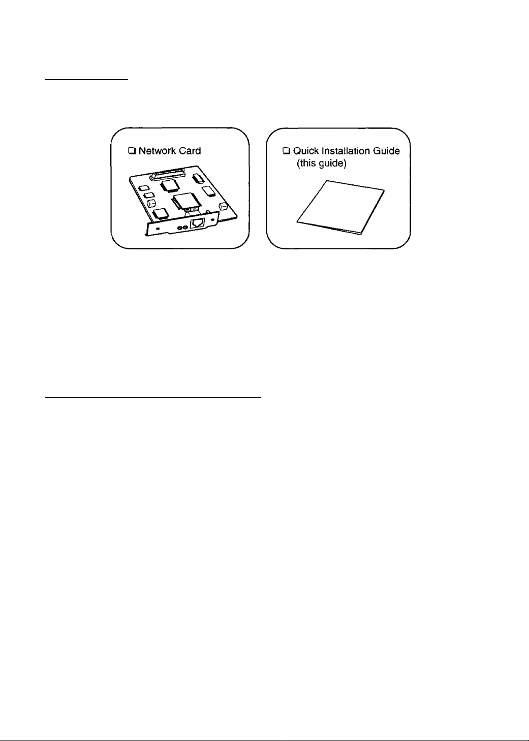
Unpacking
If you purchased the Network Card as an option, make sure that the following items are included.
Report damage or shortages to the reseller from where the Network Card was purchased.
Important
• Save the original carton and packing materials for future shipping and transporting of
the Network Card.
Installing the Network Card
Important
• To prevent damage, be sure to turn OFF the printer when installing/uninstalling the
Network Card.
• Before installing the Network Card you should discharge any static electricity by
touching any exposed metal surface on the printer, while the printer is stiii plugged
in to a grounded AC outlet.
• Do not touch any electrical components on the surface of the board to avoid static
electricity.
• Use a shielded cable when using a 100 Base-TX/10 Base-T (RJ-45 type) port to
ensure emission compliance.
• Do not remove the components which are not indicated.
Page 6
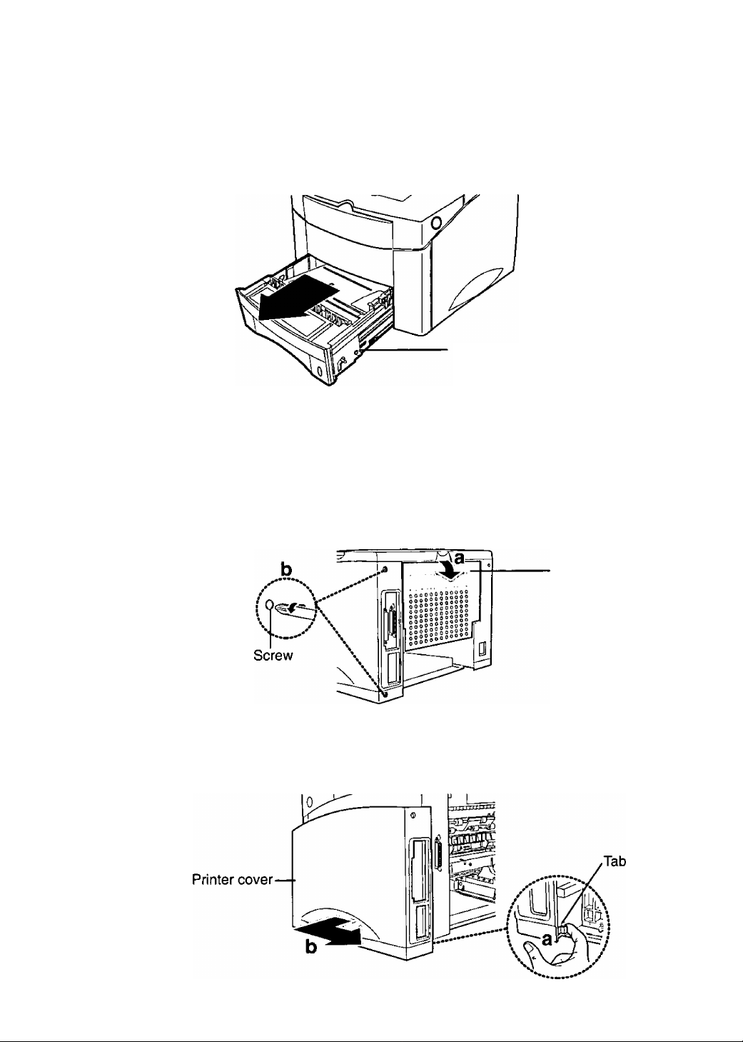
To remove the printer cover
See the “IMPORTANT’ on page 5.
1 Turn the printer OFF and pull out the 1st cassette.
2 Unplug the power cord and disconnect any cables connected to the
connectors on the back of the printer.
3 a) open the rear cover.
b) Remove the two screws from the back of the printer.
1 St cassette
a) Pull tab to release the printer cover.
b) Slide printer cover towards back of the printer.
Rear cover
Page 7
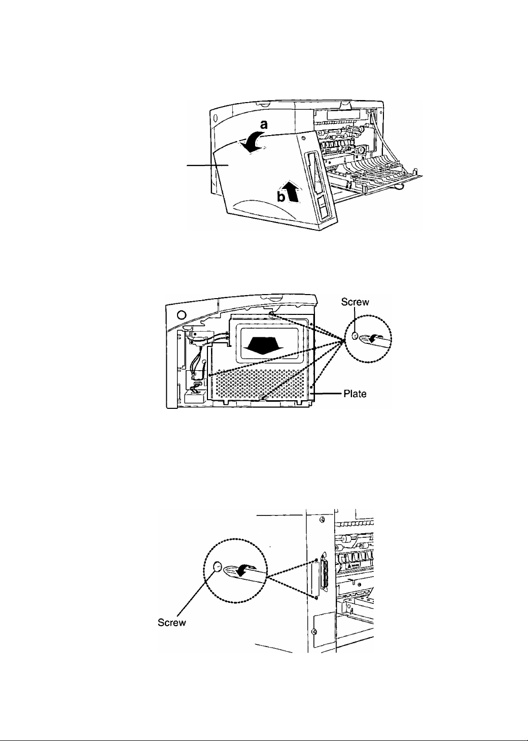
5 a) Rotate the printer cover away from the printer.
b)Lift the printer cover away.
Printer cover
6 Remove the five screws from the metal plate covering the control
board, then remove the plate.
To install the Network Card
1 Remove the two screws from the metal plate covering the opening for
the cable connector.
Page 8
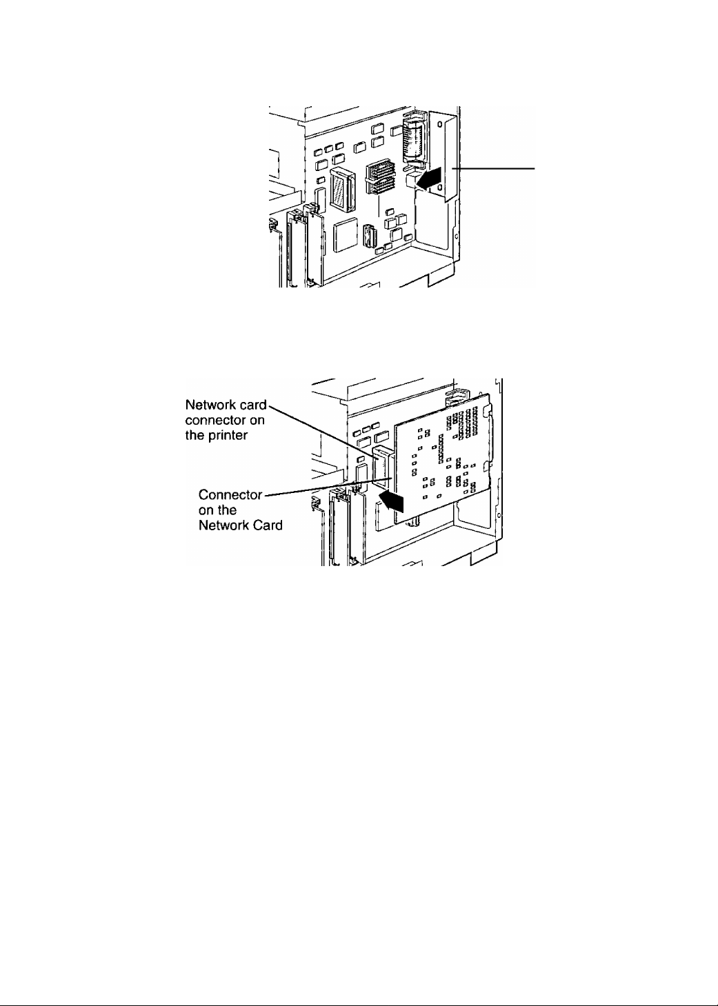
2, Remove the plate.
■ Plate
Insert the connector on the Network Card into the network card
connector on the printer control board until it is completely in place.
The two connectors should fit snugly together.
4 Gently tighten the two screws to secure the Network Card to the
printer control board.
/"■
\ Screw /
----------
\
^
8
Page 9
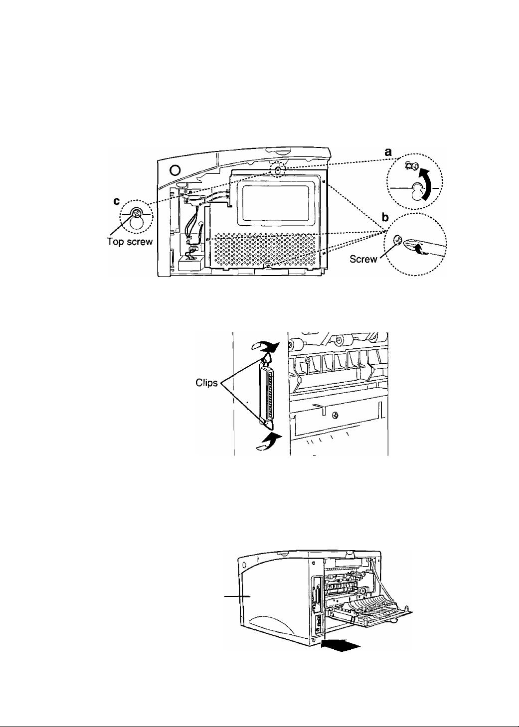
To install the printer cover
a) Replace the top screw loosely and hang the plate on it.
b) Tighten the other four screws.
c) Tighten the top screw.
6 Stand the clips on the connector to avoid hiding them behind the
printer cover.
7 Set the bottom of the printer cover onto the printer. Make sure the
bottom tabs on the printer cover fit into the corresponding slots in the
printer.
Rotate the cover up towards the printer.
Slide the cover toward the front of the printer until it clicks into place.
Printer cover
Page 10
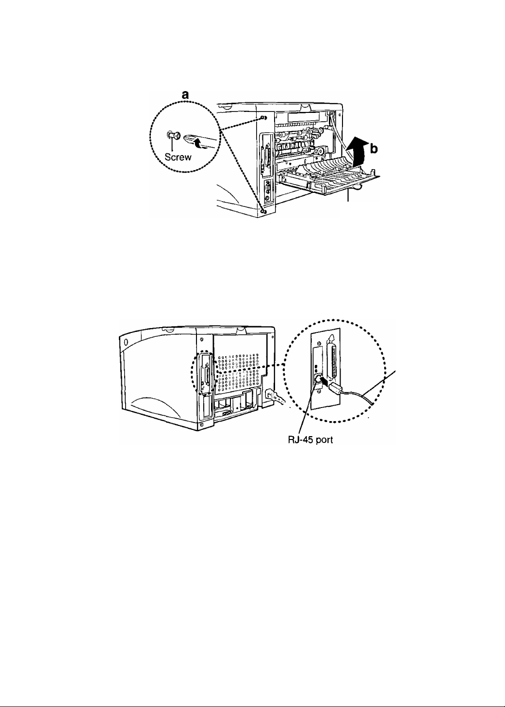
8 a) Gently tighten the two screws.
b)Close the rear cover.
Rear cover
Q Replace the 1st cassette, then reconnect any interface cables and
power cord.
10 Connect a twisted-pair network cable (not supplied) to the RJ-45
port.
, A twisted pair
network cable
11 Turn ON the printer.
Notes
• The top green LED comes on when the cable is connected to the port on the Network
Card.
• After booting, the bottom green LED should blink irregularly and the top green LED
should come on continuously.
10
Page 11

Selecting the Network Print Method
There are two ways of network printing. You may need to contact your network administrator to
select it.
• Printing directly from a computer
• Printing through the shared computer (server) (page 12)
Printing directly from a computer
A print job of a computer is transferred directly to the Network Card (printer). This method is
recommended for a small network and has the advantage of fewer setup steps. However, as the
network gets larger, there will be more network traffic causing longer waiting status for the print jobs
to be printed.
Firstly, select a network protocol which you are using or want to use.
Secondly, select the printing method.
When using TCP/IP protocol:
IP Peer-to-Peer Printing
(Windows 95/Windows 98/Windows NT 4.0)
C=>C3l=ll=IC3C=IEZIE=ll=ll=ll=IC3tn
g • LPR Printing (Windows NT 4.0)
^ When using IPX/SPX protocol:
D
D
IPX Peer-to-Peer Printing
(Windows 95/Windows 98)
D When using DLC protocol:
• DLC Peer-to-Peer Printing (Windows 95/Windows 98)
0
0
D
D
Cj
O
Q
G
See page 13.
See the KX-PNB2
User’s Guide on the
printer’s CD-ROM.
Computer C
11
o
o
a
Page 12

Printing through the shared computer (server)
A print job of a computer (client) is transferred to the Network Card (printer) by the shared computer
(server). This method requires a server and is recommended for a larger networks because it lets
the server manage the flow of print data and provides faster printing. In addition, the setup will be
easy with more computers connected in the future.
Firstly, select a network protocol which you are using or want to use on the shared computer (server).
Secondly, select the printing method.
When using TCP/IP protocol:
(P Peer-to-Peer Printing
(Server: Windows 95WVindows 98A/Vindows NT 4.0)
{p cn a cptpcjczicpcpacpolpa
LPR Printing (Server: Windows NT 4,0)
When using IPX/SPX protocol:
• IPX Peer-tO'Peer Printing
(Server: Windows 95/Windows 98)
• NetWare Printing (PSERVER/RPRINTER)
(Server, NetWare 3,x, NetWare 4.x, NetWare 5.0)
Q When using DLC protocol:
0 • DLC Peer-to-Peer Printing
0 (Server: Windows 95/Windows 98)
C3 CD CD CD CD C=l
D a C3 O CD
C3CDCDCDCDCDC3I=3C3
CD 1=3 Cn O O
See page 25.
See the KX-PNB2
User’s Guide on the
tr
printer’s CD-ROM.
0
0
D
12
(Client)
(client)
Page 13

Printing Directly from a Computer
The network printing is configured in the following outline order.
Step 1 Setting up the TCP/IP protocol on the Network Card (page 14)
Step 2 Setting up the TCP/IP protocol on the computer (page 19)
Step 3 Installing and setting up IP Peer-to-Peer printer port on the
computer (page 20) (Setting up to transfer the print job)
Print job
CO
TJ o
3 o
i-¥
5' 5'
(0(0
n Z
£:o
3|
3;
01 ?
^2.
o ^
-o o
to O
^ a
Computer A
(Windows 95/Windows 98/Windows
Windows NT 4.0) ^^,**** ^
......... /
••• 1 I .* Print job
Computer B
(Windows 95/Windows 98/
Windows NT 4.0)
(Windows 95/Windows 98/
V
When setting up direct printing on another computer:
Repeat steps 2 and 3
Printer
Computer C
Windows NT 4.0)
13
Page 14

step 1: Setting up the TCP/IP protocol on the Network Card
The setting up of IP address, Subnet Mask and Default Gateway are required for the Network Card.
Normally there are two ways to set up these addresses. You may need to ask your network
administrator about the set up of these addresses.
• By using the DHCP server
• By using the printer’s operator panel display
■ By using the DHCP server
This Network Card supports DHCP server. Therefore, it is possible to assign the IP address, etc.
automatically from the DHCP server.
Notes
• In case of the factory default, once the IP address, etc. is assigned, it will be kept in
the printer’s memory. When the printer is turned on again, the Network Card attempts
to obtain the same IP address, etc. But if the DHCP server has already lent this
address to other device, a different IP address, etc. will be assigned.
• The IP address assigned from a DHCP server has either limited or infinite lease term.
It is recommended to use Infinite lease with this Network Card. The Network Card
does not ask for an extension of the lease even if Its IP address has a limited lease
term. If the infinite IP address is assigned, the lease term is terminated when the
printer is turned off.
■ By using the printer’s operator panel display
If the administrator manages the IP address, ask your network administrator for the values. If not,
decide the value by referring to the example below.
The IP address must be unique on every network computer and device. The Subnet Mask must be
the same on all network computers and devices.
Example: Assigning the IP address. Subnet Mask and Default Gateway.
IP Address:
Subnet Mask:
Default Gateway:
Note
• It is recommended to select “DLC Peer-to -Peer printing” if you use Windows 95/
Windows 98 and you have trouble setting up the IP address values. Its settings are
comparatively easy.
10.X.X.X (For X, you can choose any number from 0 - 255 except O.O.O.O
and 255.255.255.255)
255.000.000.000
Not required.
14
Page 15

I Make sure “READY” appears on the printer’s operator panel display.
2 Press ON LINE/CONTINUE button.
3 Press MENU O button until “NETWORK MENU” appears.
4 Press ITEM O button until “CFG NET NO appears.
(Q
g
o
o
o
3
D>
o
O
3
TJ
c
o
5 Press VALUE O button, then ENTER/CANCEL button.
CFG NET
YES
t
6 Press ITEM O button until “CFG TCP NO >k” appears.
7
Press VALUE 6 button, then ENTER/CANCEL button.
CFG TCP
YES
8 Press ITEM O button.
DHCP
YES
15
Page 16

9 if “YES" appears, press VALUE O button, then ENTER/CANCEL
button.
10 Press ITEM O button.
11 \f “NO” appears, press VALUE O button, then ENTER/CANCEL
button.
CFG ADRS
YES X
12 Press ITEM O button.
r"
IP BYTE1
0 X
13 Enter the leading 3 digits of the IP Address. (To decide the value, see
the Example on paoe 14.)
• Pressing the VALUE O button once will increase the value by one.
(if you keep pressing the button, the value will continue to increase.)
• Pressing the Q VALUE button once will decrease the value by one.
The value is set at 255 after 0,
(if you keep pressing the button, the value will continue to decrease.)
14 Press ENTER/CANCEL button.
16
Page 17

15 Repeat steps 12 to 14 three times to finish entering value of the IP
address.
16 Press ENTER/CANCEL button.
17 Press ITEM 6 button.
■D
“T
5'
3
(Q
SM BYTE1
0 X
18 Enter the leading 3 digits of the Subnet Mask. (To decide the value,
see the Example on page 14.)
• Pressing the VALUE Q button once will increase the value by one.
{if you keep pressing the button, the value will continue to increase.)
• Pressing the Q VALUE button once will decrease the value by one.
The value is set at 255 after 0.
(if you keep pressing the button, the value will continue to decrease.)
SM BYTE1
XXX
+
19 Press ENTER/CANCEL button.
SM BYTE1
XXX
X
20 Repeat steps 17 to 19 three times to finish entering value of the
Subnet Mask.
O
B
fl)
o
o
B
T3
c
SM BYTE4
XXX
17
Page 18

21 Press ENTER/CANCEL button.
SM BYTE4
XXX
t
22 Press ITEM 6 button.
GW BYTE1
0 %
23 Enter the leading 3 digits of the Default Gateway. (To decide the
value, see the Example on page 14.)
• Pressing the VALUE Q button once will increase the value by one.
(if you keep pressing the button, the value will continue to increase.)
• Pressing the VALUE button once will decrease the value by one.
The value is set at 255 after 0.
(if you keep pressing the button, the value will continue to decrease.)
GW BYTE1
XXX
24 Press ENTER/CANCEL button.
GW BYTE1
XXX I
25 Repeat steps 22 to 24 three times to finish entering value of the
Default Gateway.
26 Press ENTER/CANCEL button.
27 Press ON LINE/CONTINUE button.
18
Page 19

I step 2: Setting up the TCP/IP protocol on the computer
To use IP Peer-to-Peer printing directly from the computer, the TCP/IP protocol must be installed
and set up on the computer.
If the TCP/IP protocol is used on the computer, proceed to “Step 3: Installing and setting up IP Peer-
to-Peer printer port on the computer'’ on page 20.
If not, install the TCP/IP protocol by referring to the Help menu for Windows 95, Windows 98 or
Windows NT 4.0. The IP Address, Subnet Mask and the Default Gateway must be assigned when
installing it. Set them using one of the following two ways.
If the TCP/IP protocol setting in the Network Card is set from the DHCP server, proceed to “Setting
from the DHCP server'’ below. If it is done by using printer’s operator panel display, proceed to
“Setting by direct entering” below.
■D
-T
5’
3
(O
■ Setting up from the DHCP server:
If the administrator manages the network at the DHCP server, each address Is automatically
assigned from the DHCP server.
■ Setting up by direct entering:
If the administrator manages the IP address, ask your network administrator to confirm the values,
and then enter them. If not, decide the value by referring to the example on page 14, and then enter
them.
Note
• Make sure step 1 and step 2 (page 14 to 19) are set correctly.
(1) On Windows 95/Windows 98/Windows NT 4.0, click I start], select Programs and
click MS-DOS Prompt.
(2) Type ping, press the space key, then enter the IP address.
[Example] >ping 179.40.0.5
(3) Press I Enter |.
If “Reply from XXXXXXXXXX" message is displayed on the screen, the
addresses have been set correctly. If not, those are not set correctly, and you
should go back to "Installing the Network Card” on page 5.
o
3
Q)
o
O
3
■o
c
Q
19
Page 20

Step 3: Installing and setting up IP Peer-to-Peer printer port on
the computer
■ Installing the printer driver
If the printer driver has not been installed, install it by the CD-ROM supplied with the printer. For
detailed instructions, see the printer’s Operating Instructions on the CD-ROM.
y-------------------------------------------------------------------------------------------------------------------X
Note
• If installing the PostScript printer driver, select “Local printer” when a message to
select local printer or network printer appears. And select LPT1 when available port
list appears.
V____________________________________________________________________J
Installing IP Peer-to-Peer printer port
1 Insert the CD-ROM in your CD-ROM drive.
2 Click English and click Network Utilities.
3 Select a printer model and click | Select. 4 Click I Nex^l three times.
• If installing the Network Setup Tool as the same time, click Full.
Click th« type of Sotup yo<j prefer. tKoo click
-Defer i pt i on ^
infteMotion only port »onitor for printing
through network.
< B*ck I >
5 Click Next> 6 Quit all applications and click ¡Finish
Your computer will be restarted.
20
Page 21

■ Setting up IP Peer-to-Peer printer port
<When the computer is Windows 95A/Vindows 98>
The following windows are for Windows 98.
1 Click rstart], select Settings, and click Printers.
¡£l Printeix
J Ete
]
...........................
] Addwiis |[£]
[^RSiteil Panajonic
Z obpctt^l
2
Click the printer with the Network Card installed and right-click.
Click Properties.
3
yiew Fjvoii«
-
Pthters
KX.P7500...
____
nHfxi
•m
___
Up
Di
hii
______
oiIO<-Pn>00 PCi K Pio^wiHft
3
(Q
O
3
fi)
o
o
3
T3
c
(D
4 Click the Details tab.
21
Page 22

5 Click I Add Port... I.
Select the t^pe o( port you vttri to acid
0||NetwOTy
Specilv the nelMOik path to the prhtet;
Erowte.,
;i O Q'het
I CBck the t>f№ of port you yfani to add
Local Pott
I Cl
OK
eaned
6 Click on the Other button. 7 Click KX-PNB2 Network Printer Port and click OK
I Priotet fiacrie
¿5tO!POOOOfOatM7cd
Enter Port Name: j'
!f AddNewPiirtSetvetToLBt
I MACAddee* j IPAdd^tatT
0000FCft047CD 179.40.15.220
Help
OK
]C
C«Tcd
8 Click the printer with the Network Card from the list and click [OK |.
PcNMtonic IO< PTbOO 5eiwi PCI ii P«of>eflk
D«C!4> I SImiib T _ii FjPf .
li ^
PiH ta die tidoHino ent
^FU00CIOiDt;cd ptXfNB2Ng)v«ilrPt''| li. AaiPo).. (
Plnl ifsrq Ihe fnTmnfwq dNcr
|Pmspnc ICX^VSin Sgitn PCLB
Tineoui
Poll j EfjdCaptm {
SasctSiCngt [: FVS*ens>^
' QtMl Port. 1
t| I WEjjf C^rivef. [
...
22
Cnd ; ¿pp^
9 Click roKl.
Page 23

<When the computer is Windows NT 4.0>
1
Click Start I, select Settings, and click Printers.
Click the printer with the Network Card installed and right-click.
2
Click Properties.
3
4
Click the Ports tab.
mmmsmmm
\ jj^Genwjl:' f’ortt I Stì»ÒLfirtg| j ^ Port«!
Par«™ Sw« P06
*D
5‘
s'
<o
Port
□ lpt;
□ lptj
□ COMI: Loed Port
□ comi
□ CQliO LoedPori
n rnuj
AdtfPaJ j r E^tete Port
Local Port
Local Port
Local Pori
LoedPort
....'"“‘p-'™..-
P ÌDdfale (Mnlor pocàno
Click Add Port... .
¿valatib FW» Perir
ItfJiJMgHigi
KX-PKB2 NeMk PttHei Pori
tl
LMTHirtt. DLC Ketwerk Pod
Lewnork TCP/tPNohwo»k Port
LocafPort
I 1 .] . .
______
, I ,
Add PpfL, I peto* Pori | ^onfijut* Fort.. |
J; Pimtor it*
PanatoncKX-P75... ["
.........
1 £orfisM*
I Nowi£ciL~] Ctficel I
___
^ u.._ ^
t
o
3
¿1
0)
o
o
3
■O
c
(D
nM
I
laastortj
P; Coati» poo^
23
Page 24

6 Click KX-PNB2 Network Printer Port from the [Available Printer
Ports:], and click New Port...
Prrtaf ^Janv!>
i}KXP000a0aM7cd
I I IP AdAe»
i
?ntef PoflMafne:
¿dd N<nw PiW Server To Lot
7
Click the printer with the Network Card from the list and click |OK
Click Close
8
jScheduli^[ Shared
Panftionic r>i-P7500 $crio< PClE
□ COMI; Locai Port
□ com2 Local Port
□ com2 Liicd Pot
□ COM4 CsulPat
□ RCf: Lou^Pex
ri: tli it ’ 0 J
G' poo£ng
m i v B 2 MttMtk _
-1^
griete ñü! { ^onhgmRvL
ìi
P
\
24
Click rOK
Page 25

Printing through the Shared Computer (Server)
The network printing is configured in the following outline order.
Perform steps 1 to 3 in the “Printing Directly from
a Computer” (page 14 to 24).
Change the word “computed to “server” in the sentence
when reading the steps 1 to 3.
TJ
5‘
5’
<o
o
^ TJ
(O
St0D 1 Setting up the TCP/IP protocol on the Network Card !
:_________(page 14)________________________________________jNi
‘Step 2 Setting up the TCP/IP protocol on the server (page 19)
•Steps Installing and setting up IP Peer-to-Peer printer port on the
“ server (page 20)
Step 4 Sharing the printer port on the server (page 26)
If using the separator page on the server (Windows NT 4.0):
steps Setting up the separator page on the server (page 28)
Computer A (client)
(Windows 95/Windows 98/
WindowsNT 4.0)
Shared computer \
(server) Print job
Printer
ffi (Q
¥ 5
3 (D
CD O
a ^
0 -
3 I
T5 3
£ »
5 o
^ o
1 -
Print job i ^
Computer B (client)<\ Computer C (clieht)\
(Windows 95/Windows 98/^^ (Windows 95/Windows '98/n
Windows NT 4.0)
Step 6 Setting up the printer port on
the client (page 29)
Windows NT 4.0)
When setting up another
computer:
T
Repeat step 6
25
Page 26

Step 4: Sharing the printer port on the server
Note
• If the Sharing tab does not appear during the setup, click Network Computer and in
the Properties window, set up printer as shared. For more information, refer to Help
menu for Windows 95/ Windows 98/ Windows NT 4.0.
V
__________________________________^_________________________________
<When the server is Windows 95/Windows 98>
The following windows are for Windows 98.
1
Click Start I, select Settings, and click Printers.
Click the printer with the Network Card installed and right-click.
2
Click Properties.
3
4
Click the Sharing tab.
Click on the Shared As: button, then enter the Share Name and if
5
needed, enter Comment and Password.
Panatonic ICX-P7500 Series PCL6 Properties
* ji i. ^1. Qvftbys ^ Wateimyt^
' t L Detato Sharing f P'Sfi?_I
i; ONfit Shared
jj SharedAs:--— ----
Share Kame. jKXPTSOO
1—^
----------
—v ■ ■■
/
26
iomment j
£aisvrad; |
I OK ) j
.J
i[
Apt^ j
If
Mtjp
Page 27

6 a) If you do not enter the password, click |OK
b) If you enter the password, perform the following step.
Password Confirmation
Please reenter your password to confirm it is correct.
Password;
|P~ Cancel I
□K
m
]
7 Enter the password again, then click | OK
<When the server is Windows NT 4.0>
You must logon into the server using the supervisor privilege to perform the following steps.
Click start I, select Settings, and click Printers.
1
Click the printer with the Network Card installed and right-click.
2
Click Properties.
3
4
Click the Sharing tab.
(Q
O
C
(O
<D
(/>
fi)
(D
Q.
o
o
3
T3
c
o
Click on the Shared button, then enter the Shared Name.
5
Panasonic KX-P7500 Seiles PCL6 Piopedies
Genetd I Ptali I Sehed^gji Sharing j Secuntyf^ P'yjg I
Pana*or»c(0<-P7M0SefwtPaS
O Ngl Shared
Shared
ShareNatne: |kxP7500
You rrtaiy mtal altemde chveri $o that uteri on №e ioSoM^ lyilemi can
downkiad them automatrcaV when they cwwect.
AKemate Dtiveri:
Window* 95
Window* NT 4.0 xBS [Instaled)
Wrndow* NT 4,0 MIPS
Wndow*NT 4 0A№a
Wfidow*NT 4 0PPC
Window* NT 3.5 or 3.51 )f86
To modilv the petmisitani on ^ printer, go to the Security td>.
6 Click I OK I to close the printer properties window.
M
I DK I Cancel | [ Hetp:
27
Page 28

■ If using the separator page on the server (Windows NT 4.0), proceed to step
5 below. If not, proceed to step 6 on page 29.
Step 5: Setting up the separator page on the server
# Click Start L select Settings, and click Printers.
2 Click the printer with the Network Card installed and right-click.
Click Properties.
3
4
Click the Generai tab.
28
5 Click I Separator Page... .
Sepdfdtor Pdge
pws «te u$«d at Ùit begpf^ of each
docuneni 10 mike it to Nnd a docunent among
cptheos at (he pnntar
Separator Page.
fì(0w*e ,
^ Cancel I
Click Browse...
Sepaialo) Pdge
Look in 1^ tyite>n32
Z3ceche dinetsTV Cl] Setup
Z3CertSrv DUs ^tpool
Hi config
2d dhep
ZjDrw
^ dnv«t
(Ll LogFHes
(Dos2 0 win*
Qt«
Q RepI
w
Fie r>ame:
Fios oi iype: |Sepa(ato( Page: ('tep]
£l viewef s
W pdtep
M picripLsep
EUlglPi]
:n;
?|X
fV*p(inite'
Qpen
li Ceocel
Page 29

7 Select pci.sep, then click I Open
If the PS SIMM is installed in your printer, select pscript.sep.
8
Click OK
Click OK to close the printer properties window.
9
Step 6: Setting up the printer port on the client
■ Installing the printer driver
If the printer driver has not been installed, install it by the CD-ROM supplied with the printer. For
detailed instructions, see the printer’s Operating Instructions on the CD-ROM.
Note
• If installing the PostScript printer driver, select “Local printer” when a message to
select local printer or network printer appears. And select LPT1 when available port
list appears.
Setting up the printer port
Note
• Confirm whether you can operate sever’s files from a client as indicated below.
Write down the server name and printer name because you need to enter them in
step 7 on page 30.
(1) Double-click the Network Neighborhood icon.
(2) Double-click the objective server.
(3) Shared printer should be displayed on the screen.
If not, set up the Network by referring to Windows Help.
■D
3'
5'
(Q
O
C
tQ
(D
CO
3"
0)
o
a
O
o
3
■D
C
Q
0)
O
3
(D
<When the client is Windows 95/Windows 98>
1
Click start I, select Settings, and click Printers.
2
Click the printer with the Network Card installed and right-click. Click the Properties.
3
4
Click the Details tab.
Click Add Port-
5
Click on the Network button.
6
29
Page 30

T Click I Browsed.r|.
& Double-click the server to display the printer and select the printer.
9 Click OK three times.
<When client is Windows NT 4.0>
Click Start I, select Settings, and click Printers.
1
Click the printer with the Network Card installed and right-click.
2
Click Properties.
3
Click the Ports tab.
4
Click Add Port...
5
Click Local Port from the [Available Printer Ports:], and click
6
New Port...
7 Enter the printer path name connected to the server in the following
manner, then click OK .
Wserver name*\printer name*
* The names written down on page 29 “NOTE”.
8 Click Close
9 Click I OK I to close the printer properties window.
30
Page 31

By Using the Network Setup Tool
Note
• To install the Network Setup Tool, see “ Installing IP Peer-to-Peer printer port” on
page 20.
Click Start
I,
select Programs, Panasonic, Panasonic KX-xxxx
Series, Network Setup Tool, and click Panasonic KX-xxxx Series
Network Setup Tool.
2 Click Network Interface from the Setting menu.
T3
5*
5'
to
S’
o
c
(O
S’
3
a
CO
S’
u
S
a
o
o
3
■o
c
o
-r
w
o
o
By Using the Web Browser
1 Set up the IP address and Subnet Mask on the Network Card. See
page 14. If setting up it beyond a router, the Default Gateway needs
to be set up.
If there is the printer in the intranet area, bypass the proxy server.
2 Enter http://IP address in the address bar, then press the Enter key.
CO
(D
Click Admin.
31
H
o
o
Page 32

FOR USERS IN UNITED STATES
Technical Support Calls
If you have read this manual and tried the troubleshooting procedures and you are still having
difficulty, please contact the reseller from which the unit was purchased. You may also call the
end user technical support telephone number which is operational during East Coast business
hours (9:00 AM to 7:00 PM). The end user technical support number is 1 -800-PANASYS.
This number is available within the U.S. only.
Helpful Phone Numbers
To locate your nearest sales dealer
To order consumables
To order operating instructions/CD’s
To locate your nearest authorized service center
For technical support
Automated 24-hour support via Fax back
World Wide Web Technical & Driver Support
Panasonic Document Imaging Company
Division of Matsushita Electric Corporation of America
Two Panasonic Way, Secaucus, New Jersey 07094
Panasonic Sales Company
Division of Matsushita Electric of Puerto Rico, Inc.
San Gabriel Industrial Park, 65th Infantry Avenue KM. 9.5
Carolina, Puerto Rico 00985
CALL 1 -800-742-8086
CALL 1 -800-833-9626
CALL 1 -800-833-9626
CALL 1 -800-726-2797
CALL 1 -800-PANASYS
CALL 1-800-PANASYS
http://www.panasonic.com/office/printer
Printed in Korea
Panasonic Canada Inc.
5770 Ambler Drive, Mississauga, Ontario, L4W 2T3
Matsushita Electric Industrial Co., Ltd.
Central P.O.Box 288, Osaka 530-91, Japan
JC68-00359A K0100W0
 Loading...