

Page 1
Panasonic
Laser Printer
Before operatiriQ! this unit, please read these instructlof^s completely.
Page 2
Danger: invisible laser radiation when open and interlock defeated.
Avoid direct exposure to beam.
Caution: This product utilizes a laser.
Use of control or adjustments or performance of procedures other
than those specified herein may result in hazardous radiation
exposure.
Do not open covers and do not repair yourself. Refer servicing to
qualified personnel.
Warning: To prevent fire or shock hazard, do not expose this product to rain
or any type of moisture.
The serial number of the unit may be found on the label on the rear of the unit. For your
convenience, note this number below, and retain this book, along with your proof of
purchase, to serve as a permanent record of your purchase in the event of a theft, or for
future reference.
MODEL NO. KX-P4440 NAME OF DEALER
SERIAL NO. DATE OF PURCHASE
DANGER-Invisible laser
radiation when open and
interlock defeated.
AVOID DIRECT EXPOSURE
TO BEAM.
All Rights Reserved. © COPYRIGHT 1991 KYUSHU MATSUSHITA ELECTRIC CO., LTD.
Any details given in these Operating Instructions are subject to change without notice.
Page 3

For United States Only
Important Phone Numbers:
Authorized Service Centers
Nearest Sales Dealer
To Order Consumables
Technical Support
Operating Instructions
1-800-447-4700
1-800-742-8086
1-800-346-4786
1-800-222-0584
1-206-395-7343
• HP and LaserJet are registered trademarks of Hewlett-Packard Company.
• IBM and IBM Proprinter are registered trademarks of International Business Machines
Corporation.
• Diablo is a registered trademark of Xerox Corporation.
•Times, Helvetica and Univers are trademarks of Linotype AG and/or its subsidiaries.
•CG and Intellifont are registered trademarks of Agfa Corporation.
•CG Times, based on Times New Roman under license from Monotype Corporation Pic,
is a product of Agfa Corporation.
AGFA^
Alt other acknowledgements are trademarks or registered trademarks of their respective
holders.
Intellt
Page 4

For Users in United States
This equipment has been tested and found to comply with the limits for a Class B digital
device, pursuant to Part 15 of the FCC Rules. These limits are designed to provide
reasonable protection against harmful interference in a residential installation.
This equipment generates, uses and can radiate radio frequency energy and, if not installed
and used in accordance with the instructions, may cause harmful interference to radio
communications. However, there is no guarantee that interference will not occur in a
particular installation. If this equipment does cause harmful interference to radio or televi
sion reception, which can be determined by turning the equipment off and on, the user is
encouraged to try to correct the interference by one or more of the following measures:
• Reorient or relocate the receiving antenna.
• Increase the separation between the equipment and receiver.
•Connect the equipment into an outlet on a circuit different from that to which the receiver
is connected.
• Consult the dealer or an experienced radio/TV technician for help.
The user may find the booklet “Something About Interference” available from FCC local
regional offices helpful.
FCC Warning: To assure continued FCC emission limit compliance, the user must use
only the recommended shielded interfacing cable when connecting to a host computer.
Also, any unauthorized changes or modifications to this equipment would void the users
authority to operate this device.
Technical Support Calls
If you have read this manual and tried the troubleshooting procedures and you are still
having difficulty please contact the store from which the unit was purchased.
You may also call the end user technical support telephone number which is operational
during east coast business hours (9:00 AM to 5:00 PM).
The end user technical support number is 1-800-222-0584.
For Users in Canada
L’interférence radioélectrique générée par cet appareil numérique de type B ne dépasse
pas les limites énoncées dans le Règlement sur les perturbations radioélectriques, section
appareil numérique, du Ministère des Communications.
This digital apparatus does not exceed the Class B limits for radio noise emissions from
digital apparatus set out in the Radio Interference Regulations of the Canadian Department
of Communications.
Page 5

Table of Contents
Your New Laser Printer—A Guided Tour Page
1.
1.1 Product Overview........................................................................................ 1-1
1.2 Part Names ................................................................................................. 1-2
Front and Right Side View
Rear and Left Side View............................................................................. 1-2
Inside View................................................................................................. 1-3
Installation and Initial Setup
2.
2.1 Unpacking and Inspection........................................................................... 2-1
2.2 Installation Requirements
Environment................................................................................................ 2-2
Minimum Space ......................................................................................... 2-2
Power Source ............................................................................................. 2-2
2.3 Installing Developer Unit (with Toner Cartridge),
Drum Unit, Power Cord and Face Up Output Tray
Developer Unit (with Toner Cartridge)...................................................... 2-3
Drum Unit .................................................................................................. 2-7
Power Cord ................................................................................................ 2-9
Face Up Output Tray . :
Output Tray Selector..................................................................................... 2-10
Output Tray Extender.................................................................................... 2-10
2.4 Interfacing—Connecting Your Printer and Computer ... 2-11
Connect the Parallel Interface Cable............................................................. 2-12
Connect the Serial Interface Cable................................................................ 2-13
2.5 Power On....................................................................................................... 2-14
2.6 Loading Paper and Installing Paper Cassettes.............................................. 2-15
Loading Paper Except Legal Size Paper ...................................................... 2-15
Loading Legal Paper
2.7 Manual Feed.................................................................................................. 2-22
Setting the Manual Feed by the Front Panel................................................. 2-22
Loading Paper for the Manual Feed
2.8 Envelopes....................................................................................................... 2-25
Using Manual Feed....................................................................................... 2-25
Using Upper Paper Cassette.......................................................................... 2-26
2.9 Test Printing.................................................................................................. 2-29
Status Printing................................................................................................ 2-29
Font List Printing .......................................................................................... 2-30
Character Printing......................................................................................... 2-31
........................................................................
...........................................................................
...................................
..............................................................................
.....................................................................................
.............................................................
1-2
2-2
2-3
B
2-9
2-19
2-23
D
Page 6

Table of Contents
3. Front Panel—All It Takes Is a Touch Page
3.1 Front Panel Description............................................................................... 3-1
3.2 What You Can Perform Through the Front Panel
Easy Access to Menu Mode........................................................................ 3-6
EMULATION Menu................................................................................... 3-8
—Selecting the Emulation....................................................................... 3-9
COPY Menu................................................................................................ 3-11
—Setting the Number of Copies
—Setting the Verify Mode
MANUAL FEED Menu ............................................................................... 3-16
—Selecting the Manual Feed
FONT Menu................................................................................................. 3-17
—Selecting the Resident Font
—Selecting the Font Card, Soft Font, Uploaded Font or
Upload Font Card .......................................................................... 3-23
—Setting the Zero Character .................................................................. 3-25
—Setting the Font Group......................................................................... 3-26
CASSETTE Menu....................................................................................... 3-27
—Selecting the Paper Feed from the Cassette
—Formatting the Page............................................................................. 3-30
OTHER Menu ............................................................................................. 3-32
—Setting the Other Menu........................................................................ 3-34
INTERFACE Menu ...................................................................................... 3-36
—Setting the Parameter of RS-232C
—Selecting the Interface
3.3 When You Wish to RESET/TEST 3 40
Using the RESET Key................................................................................... 3-40
— Resetting the Printer
Using the TEST Key..................................................................................... 3-42
—Performing the Test Print (Status Print, Font List Print or
Character Print).............................................................................. 3-42
—Checking the Remaining Memory Capacity
3.4 Factory Default Settings.............................................................................. 3-44
3.5 The RS-232C Defaults
.........................................................................
.............................................................................
...............................................................................
............................................................
.....................................................................
...................................................................
.................................................................
........................................................
.....................................
.......................................
......................................
3-5
3-12
3-13
3-16
3-21
3-29
3-36
3-38
3-40
3-43
3-44
4. Using Your Laser Printer
4.1 General Guidelines...................................................................................... 4-1
4.2 Configuring Your Computer....................................................................... 4-1
4.3 Configuring Your Printer
Configuring Your Emulation
Configuring Your Font Group .................................................................... 4-4
Configuring Your Printer Interface............................................................. 4-4
4.4 Configuring Your Software......................................................................... 4-5
...........................................................................
.....................................................................
4-2
4-2
Page 7

Table of Contents
5. Care and Maintenance of Your Laser Printer Page
5.1 How to Maintain and Change
Changing Cleaning Pad and Toner Cartridge (KX-P453)
Changing Drum Unit and Ozone Filter (KX-PDM5)
Changing Developer Unit with Toner Cartridge (KX-PDP5)
5.2 Cleaning the Printer .........
Cleaning the Outside of the Printer
Cleaning the Inside of the Printer
5.3 How to Clear a Paper Jam............................................................................... 5-14
Paper Jam 1 .................................................................................................... 5-14
Paper Jam 2 .................................................................................................... 5-15
Paper Jam 3 .................................................................................................... 5-17
If Paper Jam Still Occurs in the Fuser Unit................................................ 5-19
5.4 How to Adjust Print Density........................................................................... 5-21
5.5 How to Clean the Tungsten Wire
5.6 Periodic Maintenance...................................................................................... 5-23
Resetting the LCD Messages
5.7 Troubleshooting ............................................................................................. 5-24
5.8 Repacking Instructions ................................................................................... 5-29
.........................................................................
........................
................................
..................
..............................................................................
...........................................................
...................................................................
............................................................
.........................................................................
5-1
5-5
5-8
5-12
5-1
5-12
5-12
5-22
5-23
B
6. Specifications
6.1 Printer Specifications...................................................................................... 6-1
6.2 Paper Specifications...............................................................'
General Guidelines.......................................................................................... 6-2
Paper Specifications........................................................................................ 6-2
Types of Paper to Avoid
Paper Sizes...................................................................................................... 6-3
OHP Film and Labels ..................................................................................... 6-4
Duplex Printing (Double Sided Printing)
Envelope Specifications.................................................................................. 6-5
6.3 Interface Specifications .................................................................................. 6-7
Parallel Interface............................................................................................. 6-7
Serial Interface ............................................................................................... 6-11
Appendix A Resident Font Print Sample .................................................... A-l
Appendix B Options, Accessories and Supplies.................................... B-1
Glossary ............................................................................................................................ G-1
Index .............................................................................................................................. i-i
................................................................................
.......................................................
....................
6-2
6-3
6-4
B
fl
Page 8

Preventive Maintenance
• Keep all liquids away from the printer. Accidental spillage of a liquid
into the printer can cause severe damage.
• Do not block the air flow around the printer. Do not place books, paper,
or other items on the top of the printer.
•Special care should be taken to protect the printer if it is used in an
unfriendly environment such as a machine shop, a dusty or sandy area,
etc.
• If the printer is not going to be used for an extended period, unplug the
power cord.
• Do not open the cover while in operation.
• Do not leave the paper cassette loaded with paper in a high humidity
area when not used.
• Keep the paper cassette away from dust when not used.
• Do not add paper to the paper cassette while paper remains in it.
Page 9

1. Your New Laser Printer—A Guided Tour
1.1 Product Overview
Congratulations on your purchase of the printer. No matter why you
purchased this printer we are sure it will meet your printing needs and
give you many years of productive and efficient use.
Printing speed:
Paper input:
Paper output:
Interfaces:
Emulations:
Internal memory:
Fonts:
10 pages per minute (Letter size paper, text mode, 5.5%
image area, all originals)
Upper; Multi purpose paper cassette with manual feed
Lower; Multi purpose paper cassette
Face up and face down paper output
Centronics parallel and RS-232C serial
HP LaserJet Series III
Diablo 630
IBM Proprinter II
1 MB (expandable to maximum 5 MB with optional
0 MB RAM Expansion Module plus 1 MB SIMM or
2 MB SIMM)
22 resident
• 14 Bitmap fonts available in both portrait and landscape
•8 Outline fonts
(Intellifont Scalable Typefaces)
SatinPrint:
Panasonic’s SatinPrint technology reduces “jaggies”
creating a much smoother looking output.
By interspacing standard 300 DPI dots at 600 DPI
addresses and adding in 600 DPI dots where necessary,
SatinPrint provides higher quality output than is available
from conventional 300 DPI laser printers.
Your New Laser Printer—A Guided Tour 1-1
Page 10
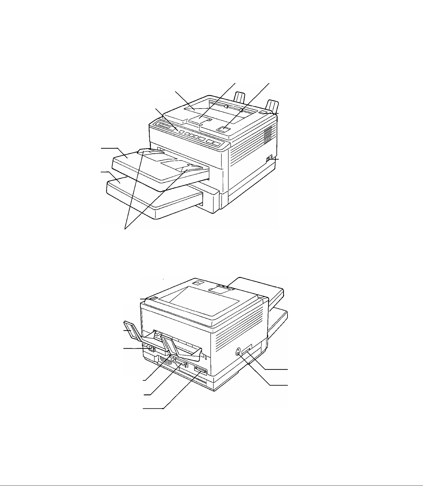
1.2 Part Names
(Front and Right Side View)
Face down output tray
Output tray extender ^— Clamshell release button
Front panel
Upper
paper cassette
Lower
paper cassette
Manual feed
guides
(Rear and Left Side View)
•Output tray selector
■Power switch
Output tray selector
Face up output tray-
Power connector plug.
Frame ground terminal
Parallel interface connector
Serial interface connector -
7-2 Your New Laser Printer—A Guided Tour
Font card slot
• Print density dial
Page 11
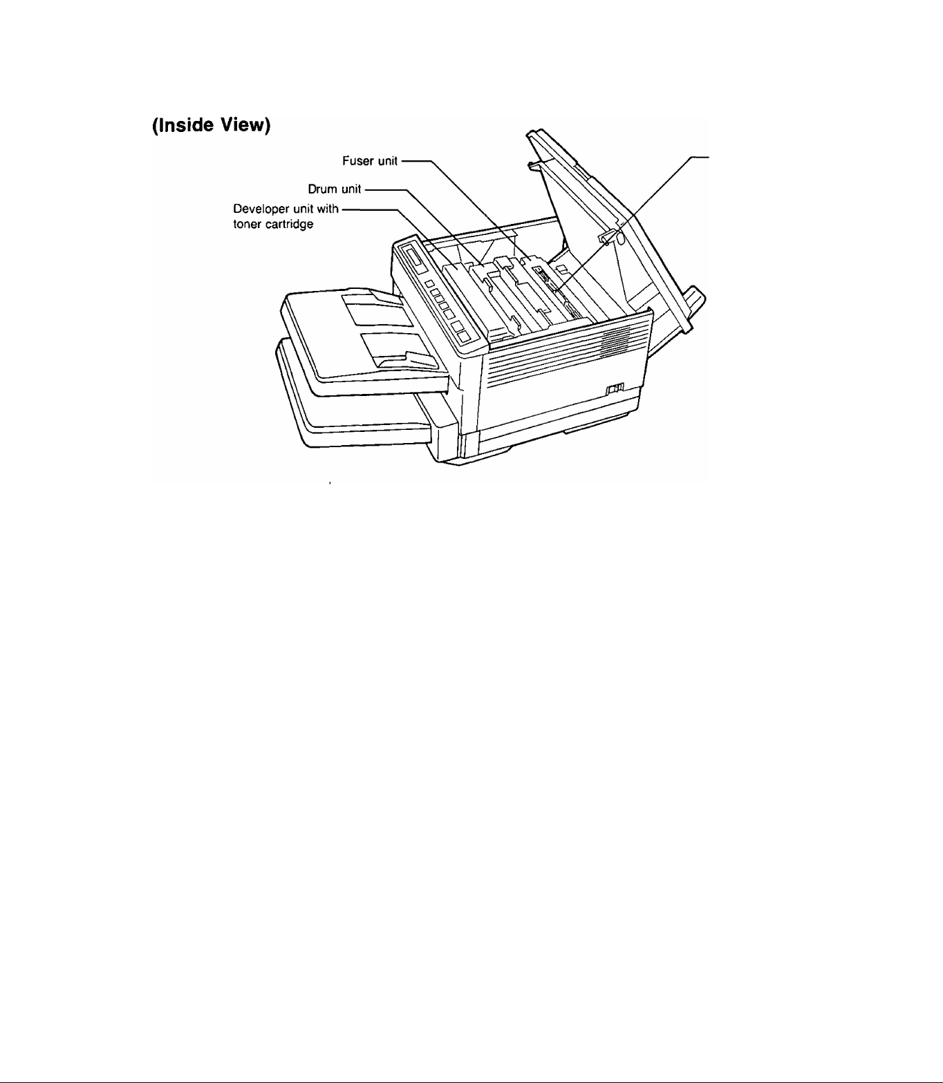
Cleaning pad
Your New Laser Printer—A Guided Tour. 1~3
Page 12

1-4 Your New Laser Printer~A Guided Tour
Page 13
2. Installation and Initial Setup
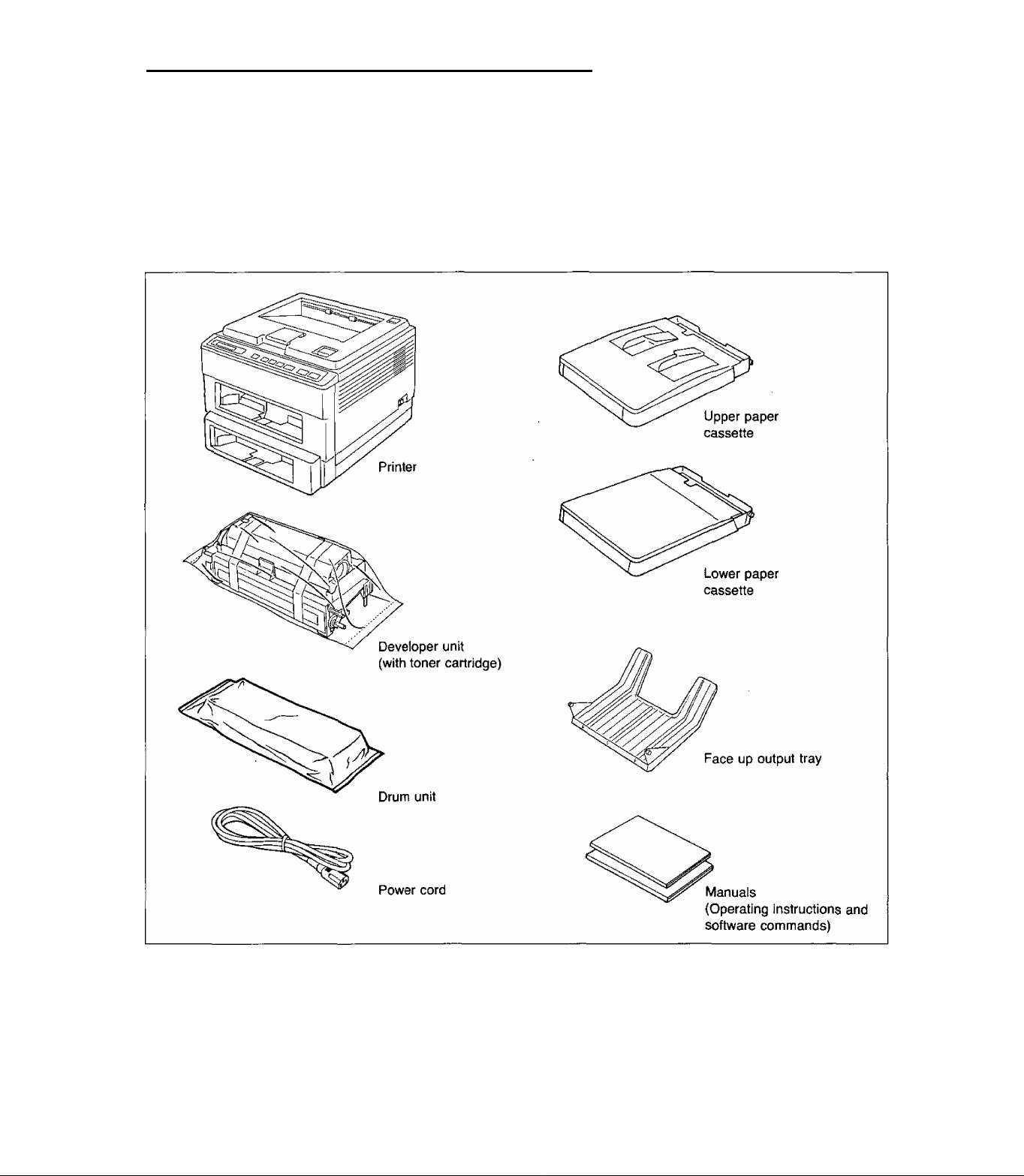
2.1 Unpacking and Inspection
Carefully open the shipping carton and remove the contents. The figure
below shows the items that the carton should contain. Inspect the printer
and accessories for damage. Report damage or shortages to the store from
which the unit was purchased. Inside the front cover of this manual is an
area for recording important information regarding the printer. Please
record the serial number, date of purchase and your dealer’s name.
Note:
Please keep all packing materials so that they may be used if you
transport the printer in the future. They have been specifically
designed to protect your printer during shipment.
Installation and Initial Setup 2-1
Page 14
2.2 Installation Requirements
Environment
•Temperature Range: 50° to 90.5^ (10° to 32.5°C)
• Humidity Range: 20% to 80% RH
• Do not install the printer under the following conditions:
— Extremely high or low temperature or
extremely high or low humidity
— Direct exposure to sunlight
— Areas of high dust concentration
— Areas of poor ventilation
—Areas with chemical fume concentration
— Areas with extreme vibration
— Directly in front of air conditioning vents
• Place the printer on a stable, level table.
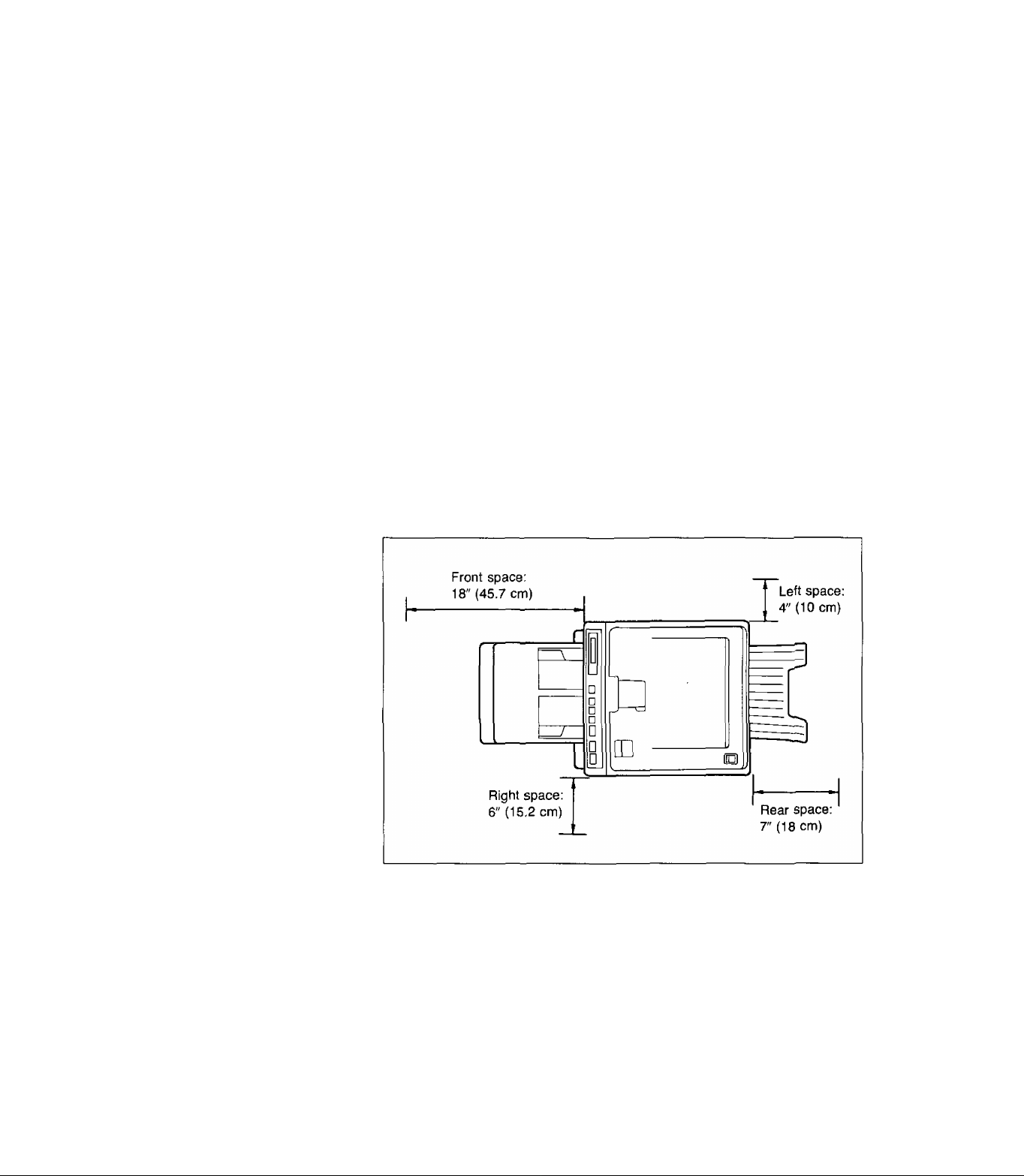
Minimum Space
Minimum space requirements for setup are shown below.
Power Source
2-2 Installation and Initial Setup
• Use a voltage level which does not vary more than ±10% from the
voltage level marked on the nameplate (located on the rear of the
printer).
•Do not use an extension cord.
•This printer should be connected to a grounded outlet.
•Do not use a line conditioner, transient suppressor, or surge protector.
Page 15
2.3 Installing Developer Unit (with Toner Cartridge),
Drum Unit, Power Cord and Face Up Output Tray
Developer Unit
(with Toner Cartridge)
Important:
The developer unit contains developer for printing.
• Keep the developer unit away from dust and small objects.
• Do not place the developer unit in a high humidity or high tem
perature area.
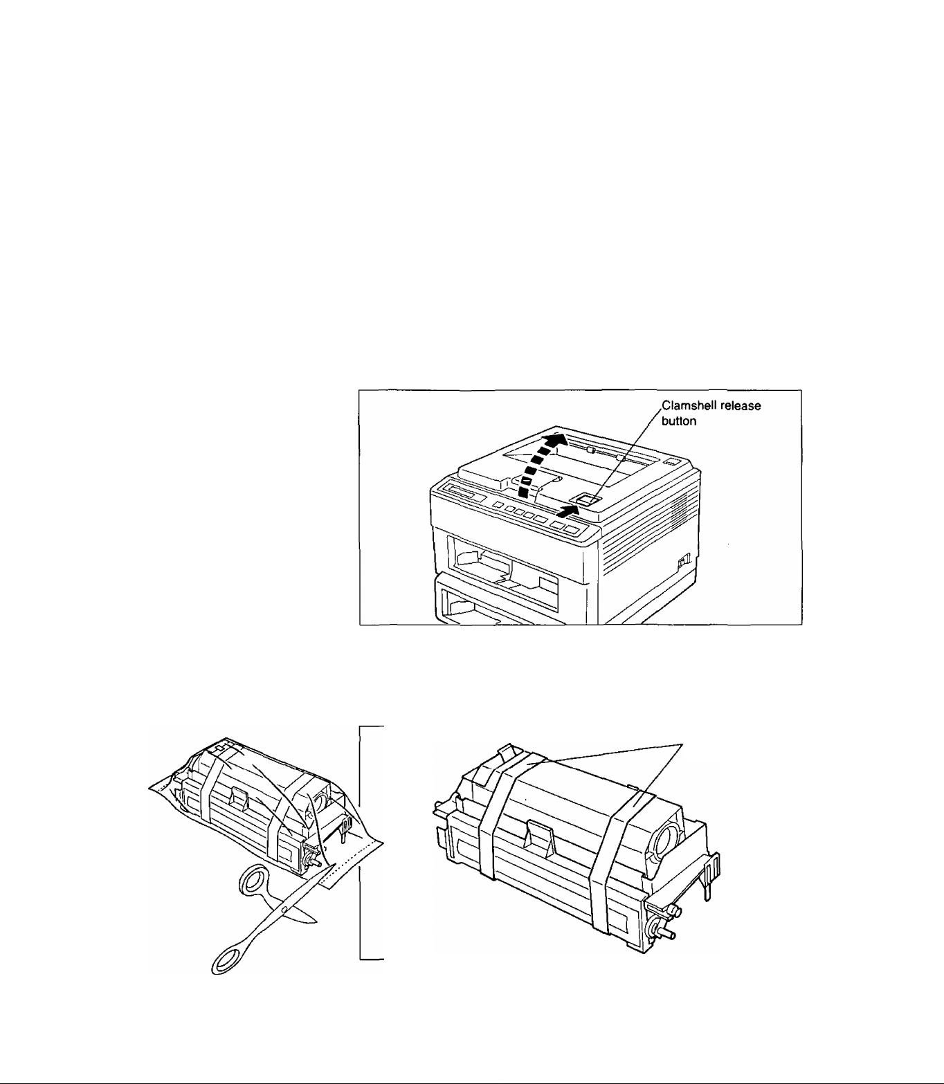
Press clamshell release button. Clamshell will open automatically.
1
2
Open protective bag.
Take out developer unit and remove tape.
Tape
Installation and Initial Setup 2-3
Page 16
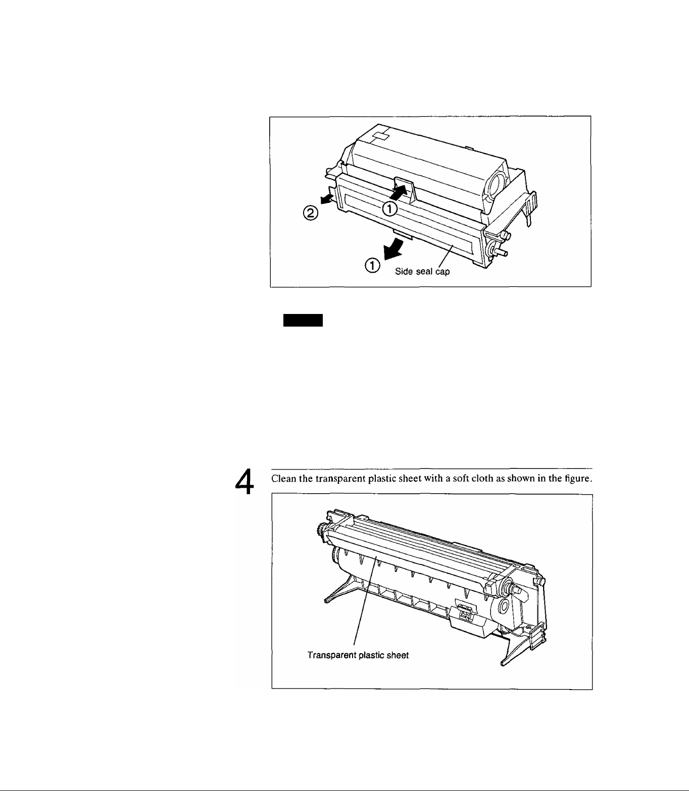
3
While keeping developer unit horizontal, remove side seal cap.
© Push top tab while pulling bottom tab.
@ Pull side tab.
('aiilidii
Be sure not to touch exposed developer after you remove the side
seal cap.
Note:
Please keep the side seal cap in the event the printer must be
repacked.
2-4 Installation and Initial Setup
Page 17
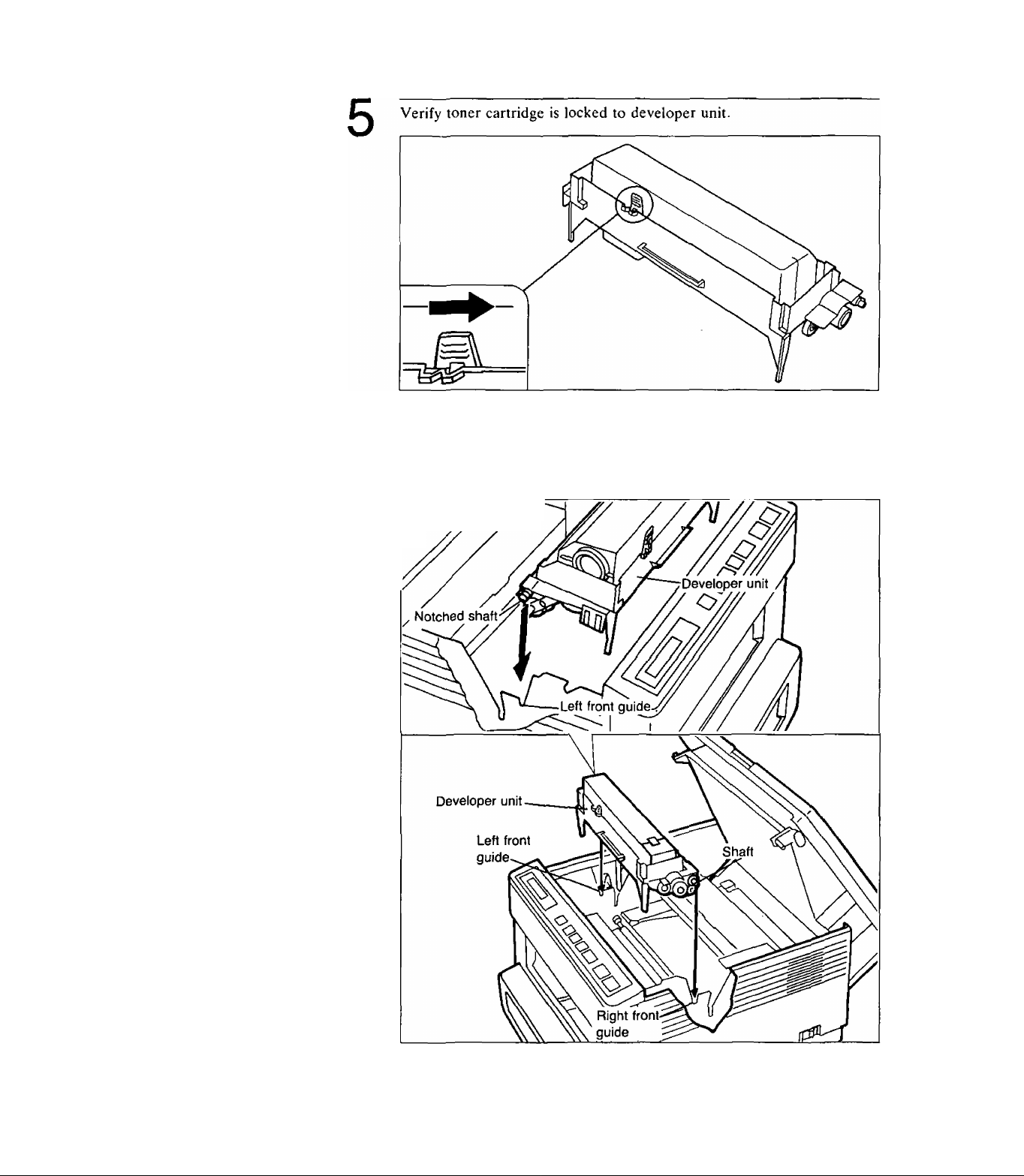
6
Install developer unit in front guides.
Be sure left notched shaft sets properly in left front guide.
///
Left side view
V
installation and Initial Setup 2-5
Page 18
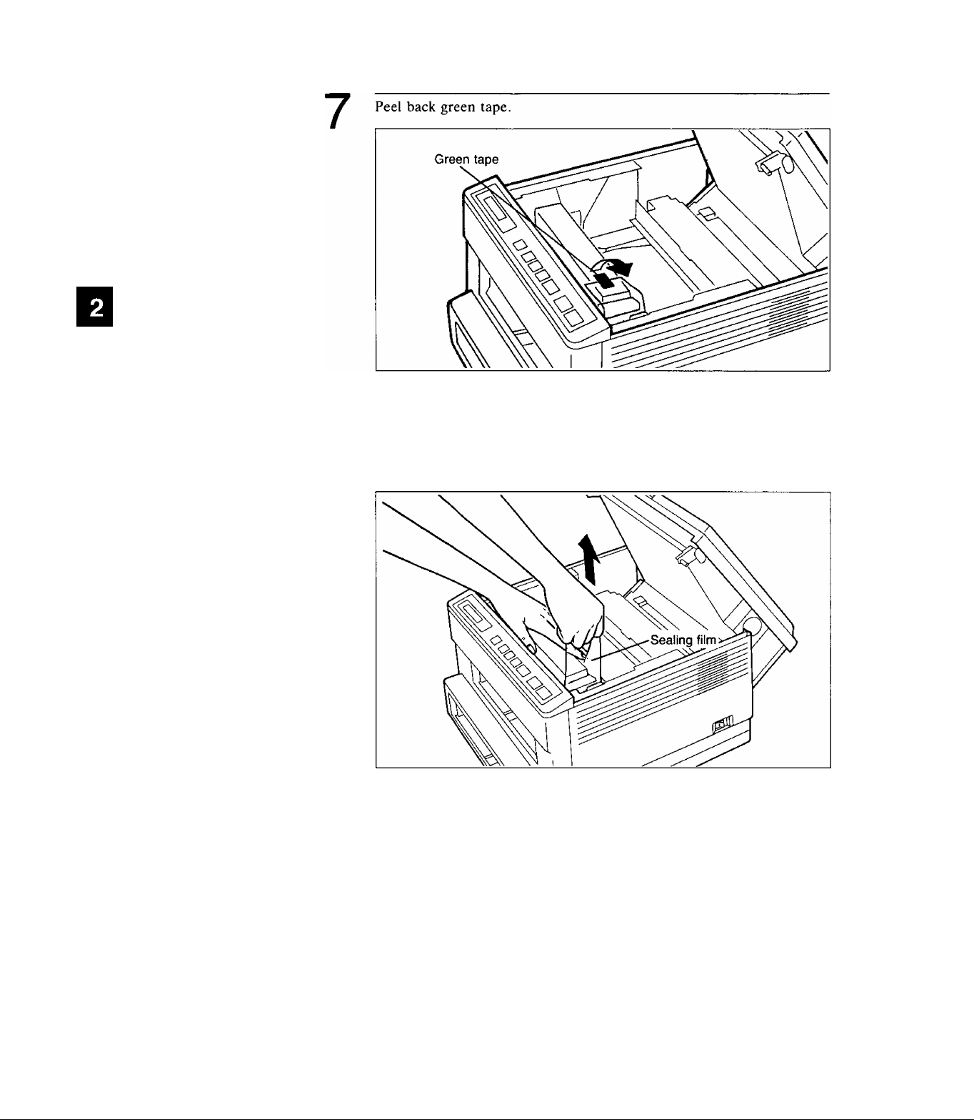
8
Hold developer unit in place, grasp clear plastic sealing film and pull
upward to completely remove.
Lightly tap top of toner cartridge to empty toner into developer unit.
Note:
Be careful handling sealing film since some toner residue may re
main.
2-6 Installation and Initial Setup
Page 19
Drum Unit
1
Important:
The drum unit contains a photosensitive drum. Exposing it to light
may damage the drum. Do not open the protective bag until you’ve
read the following instructions and are ready to install the drum unit.
Once you’ve opened the protective bag:
• Do not expose the drum unit to light for more than 5 minutes.
• Do not touch the yellowish-green drum surface. Lift the drum unit
by the green labeled tabs.
• Keep the drum unit away from dust or dirt.
• Do not place the drum unit in a high humidity area, and keep it
out of direct sunlight.
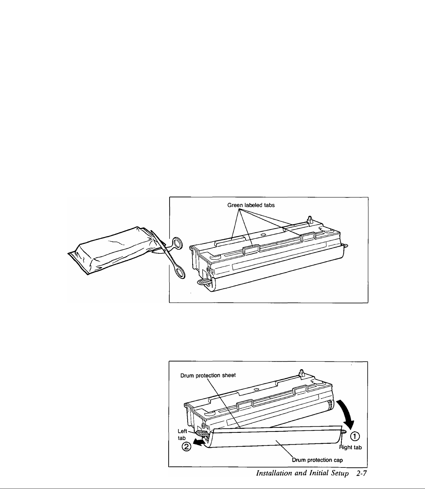
Open protective bag.
Take out drum unit.
Lift the drum unit by the green labeled tabs.
2
Remove drum protection cap and drum protection sheet by releasing right
and left tabs.
Do not expose the drum unit to light for more than 5 minutes.
Do not touch the yellowish-green drum surface.
Page 20
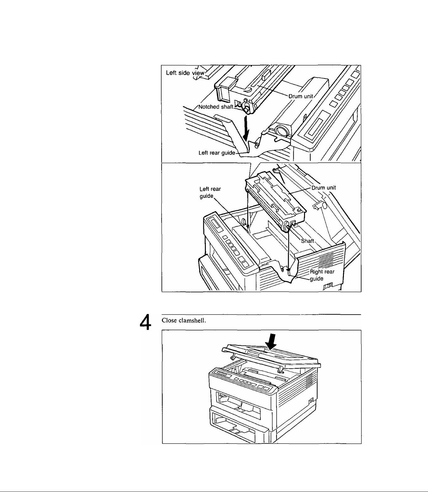
3
Install drum unit in rear guides.
Be sure left notched shaft sets properly in left rear guide.
2-8 Installation and Initial Setup
Page 21
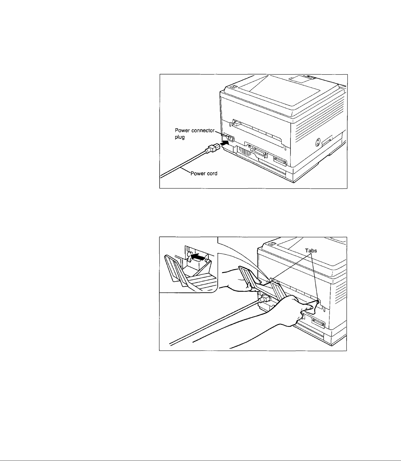
Power Cord
Face Up Output Tray
Connect power cord.
Be sure to turn OFF the power switch before you connect the power cord.
Insert left and right tabs as shown below.
Note:
•Do not print more than 20 sheets at one time [75 g/m^ (20 lb.)]
through the face up output tray. This may cause a paper jam.
•Print envelopes, OHP film and labels using the face up output tray
to prevent jamming.
Installation and Initial Setup 2-9
Page 22
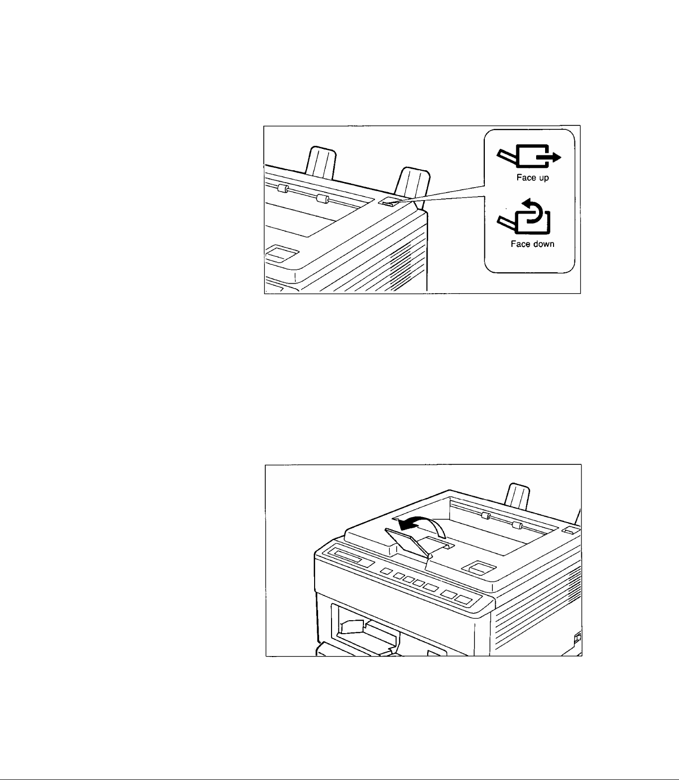
Output Tray Selector
The output tray selector switches the paper output between face up and
face down.
Note:
Do not switch the paper output while the printer is ejecting the
paper. This may cause a paper jam.
Output Tray Extender
When using the face down output tray, flip the output tray extender
forward.
2-10 Installation and Initial Setup
Page 23

2.4 Interfacing—Connecting Your Printer and Computer
The printer will operate with either a parallel or serial interface. It
automatically selects the active interface when both are connected and
Auto Switch is selected through the front panel.
If you do not have an interface cable, you will need to purchase one from
your local computer store or dealer.
Installation and Initial Setup 2-11
Page 24
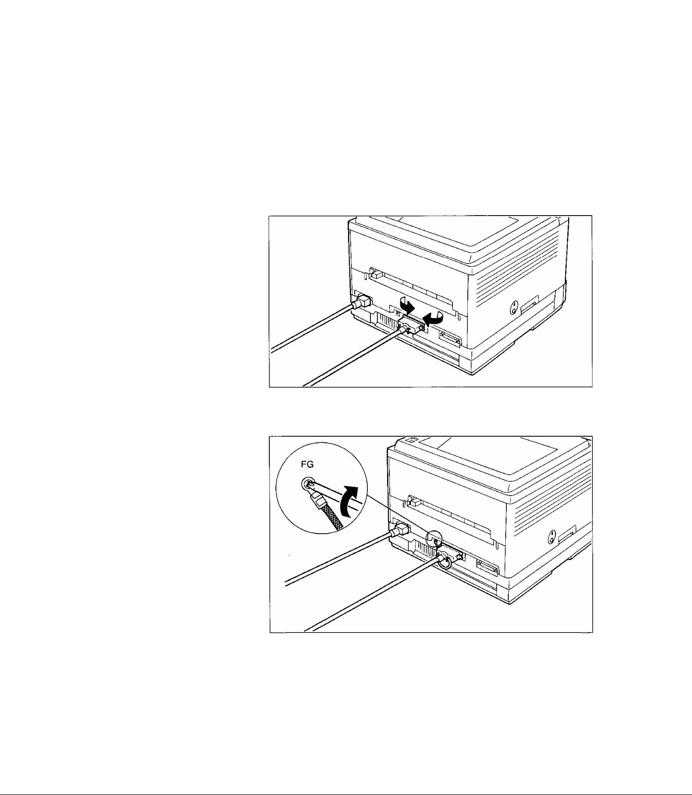
Connect the Parallel
Interface Cable
1
2
Turn OFF both the printer and computer power switches.
Plug one end of the cable into the parallel interface connector of the
printer.
Snap the clips into place.
3
If the cable has a frame ground wire, connect it to the frame ground
terminal.
Plug the other end of the cable into the connector of the computer.
2-12 Installation and Initial Setup
Page 25
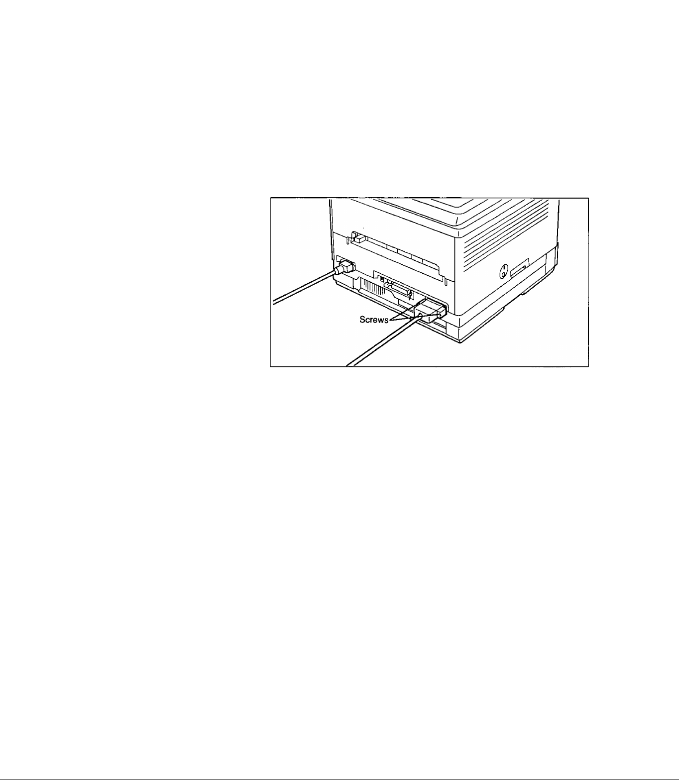
Connect the Serial
Interface Cable
1
2
Turn OFF both the printer and computer power switches.
Plug one end of the cable into the serial interface connector of the printer.
Tighten screws.
3
Plug the other end of the cable into the connector of the computer.
Installation and Initial Setup 2-13
Page 26
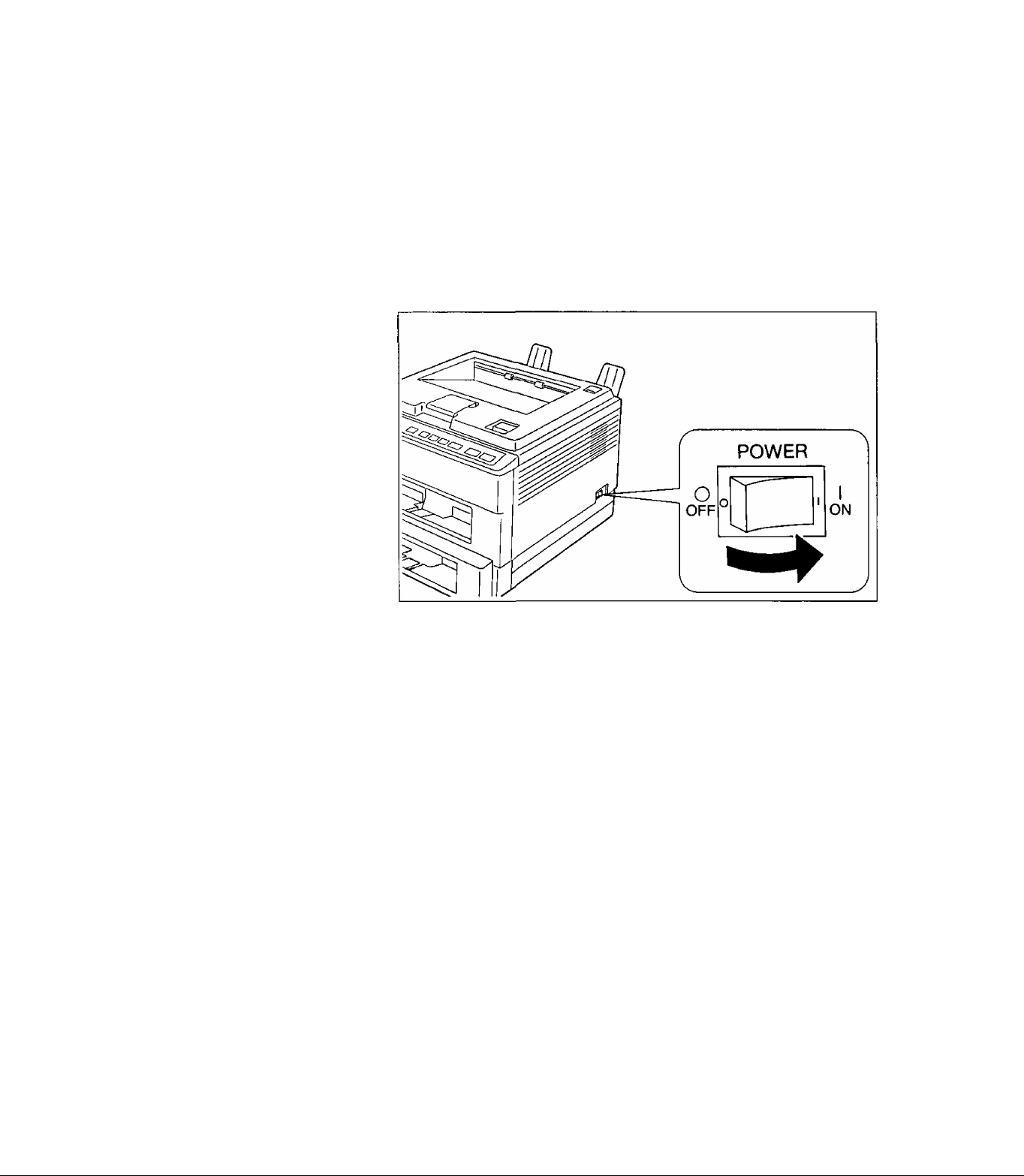
2.5 Power On
Make sure the printer is plugged into a 3 prong AC socket. The following
procedures should be followed when turning the printer ON.
Plug the power cord into the outlet.
1
Turn the power ON.
2
The display will show:
WARM UP
After about 1.5 minutes, if the paper cassettes are not installed, the
display will show:
PAPER EMPTY U11
Refer to the next section, to install the paper cassettes.
Note:
If error messages other than “PAPER EMPTY U11” are displayed,
refer to Section 5.7 for clearing error messages.
00
2-14 Installation and Initial Setup
Page 27

2.6 Loading Paper and Installing Paper Cassettes
This printer has mutti purpose upper and lower paper cassettes, and the
upper cassette has a manual feed function.
You can adjust the cassettes from envelope size to legal size.
Size
Feed^'\.^
Lower
Cassette
Upper
Cassette
Manual
Feed
Table 2.1 Available Paper Size
Except Legal Size
Letter Legal
O O o
O o
0
Loading Paper
Paper
A4 Executive Envelope
O
o o — —
o o o
Envelopes must meet specifications. (For details refer to pages 6-5 and
6-6.)
The paper size selected through the front panel or software commands
should match the size of the paper in the cassette. If the selected paper size
is different from the installed paper size, a paper jam may occur. Refer to
“CASSETTE Menu” on page 3-27 for page formatting.
—
0*1
OHP Film
—
O O
Label
1
Paper is loaded into the upper and lower cassette in the same manner.
The figure below shows the upper cassette.
Remove paper cassette cover.
Installation and Initial Setup 2-15
Page 28

3
Place paper in paper cassette.
The height of the paper should not exceed the limit mark on the paper
cassette.
Notes:
•Do not load different types or thickness of paper in the same
cassette since this may cause a paper jam.
•Make sure you load the paper with the print side up. Most paper
has instructions recommending the side to be printed first. Please
follow these instructions when you load the paper cassette. How
ever, when using 16 lb (60 g/m^) paper, always load the paper with
the “non-curl side” up rather than following the instructions on
the paper package.
•For more detailed information on paper, refer to “Paper Specifi
cations” in Section 6.2 on page 6-2.
2-16 Installation and Initial Setup
Page 29
4
Adjust the rear and side paper guides to the correct paper size.
Be sure the edges of the paper are under the tabs.
Note:
Properly adjust the side paper guides to fit the paper snugly. Im
proper adjustment may cause skewed paper-feeding, improper
printing or a paper jam.
Installation and Initial Setup 2-17
Page 30

6
7
Insert paper cassette into upper (lower) front opening.
Make sure output tray extender is forward.
Verify the front panel displays the following message:
OFF LINE
8
Set the paper size through the front panel. (Refer to page 3-27.)
Notes:
•The paper cassette with manual feed should be installed in the
upper front opening.
• Failure to insert the tabs on the cassette sides into the edges in the
printer completely may cause a paper jam or skewed paper-feed
ing.
Caution
When setting up the printer for the first time, please allow the
printer to warm-up before installing the paper cassette. Installation
of the paper cassette before the warm-up period is complete may
result in a paper jam If a paper jam does occur please refer to
Section 5.3.
2-18 Installation and Initial Setup
Page 31

Loading Legal Paper
(8WX14")
1
2
Remove paper cassette cover.
Pull down legal paper guide while pressing both sides of the paper cassette
to the outside.
Installation and Initial Setup 2-19
Page 32

5
6
7
Fan the stack of paper.
Place legal paper in paper cassette. Do not exceed the paper limit mark.
Adjust the side paper guides to the paper size.
Be sure the edges of the paper are under the tabs.
2-20 Installation and Initial Setup
Note:
Properly adjust the side paper guides to the paper. Improper adjust
ment may cause skewed paper-feeding, improper printing or a paper
jam.
Page 33

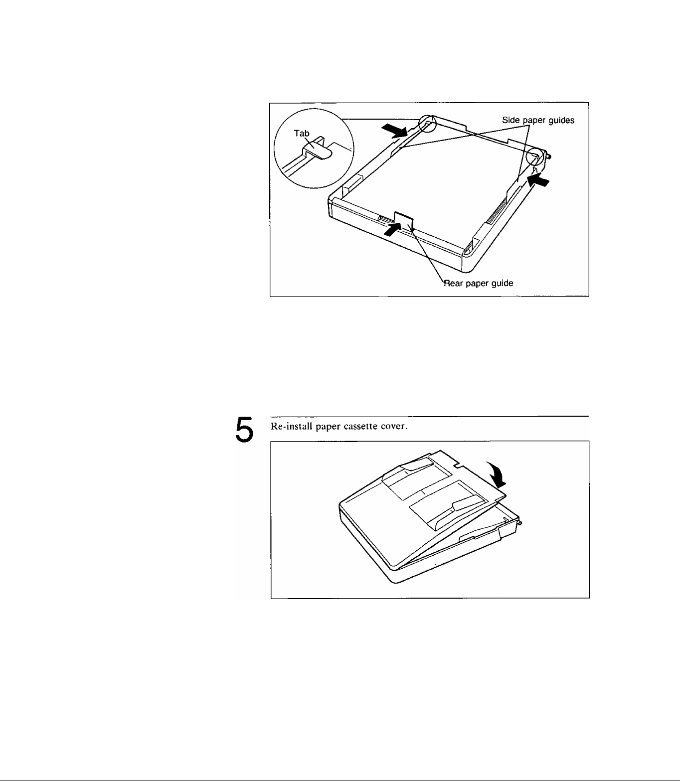
8
9
Re-install paper cassette cover.
Insert paper cassette into upper (lower) front opening.
Make sure output tray extender is forward.
10
Note:
Failure to insert the tabs on the cassette sides into the edges in the
printer completely may cause a paper jam or skewed paper-feeding.
Set the paper size to legal through the front panel. (Refer to page 3-28.)
Installation and initial Setup 2-21
Page 34

2.7 Manual Feed
Setting the Manual
Feed through the
Front Panel
If you wish to print a single sheet of different size paper, you should use
the manual feed function.
Before installing the paper, set the manual feed using the front panel
(refer to page 3-27) or through software commands (refer to the “Paper
Input Control” on the
Software Commands Manual).
1
2
3
4
5
Operation
Press
ON LINE
Press
MENU
Press
O/Q
Press
ENTER
k
________
Press
GD/G
Display/Description
OFF LINE
EMULATION
Press the key until the display shows:
MANUAL FEED
OFF^'
*
ON
Press
6
Press
7
ENTER
ON LINE
2-22 Installation and Initial Setup
Manual feed is operational.
OFF LINE
The MANUAL indicator will be lit.
ON LINE
Page 35

Loading Paper for
the Manual Feed
1
2
Adjust manual feed guides to accomodate your sheet of paper.
Be sure that the MANUAL indicator is lit.
Insert a sheet of paper between manual feed guides until you feel resis
tance.
3
Send data from the computer to the printer.
The printer will start printing when the print data transfer has been
completed.
Installation and Initial Setup 2~23
Page 36

Cilutiol)
• Do not insert paper while the printer is feeding paper since this
may cause a paper jam.
•When you use the manual feed function, the paper cassette should
contain paper since a jam may occur if the cassette is empty.
Notes:
•The paper cassette with manual feed must be on the upper cas
sette.
• Labels and OHP films should use the manual feed function.
• We recommend using manual feed when you print envelopes.
• Print envelopes, labels and OHP films using the face up output
tray to prevent creasing.
•Minimum and maximum paper dimensions that can be fed from
the manual feed are shown below.
Paper size:
Width; 3.5" (88 mm) to 8.5" (216 mm)
Length; 6.3" (160 mm) to 14" (355.6 mm)
Weight: 16 to 35 pounds (60 g/m^ to 135 g/m^)
2-24 Installation and Initial Setup
Page 37

2.8 Envelopes
Using Manual Feed
1
This printer prints envelopes by using either the manual feed or multi
purpose paper cassette.
You can use Business Commercial #10, Business Commercial #9, Mon
arch, International DL and International C5 (manual feed only).
However, when using the multi purpose paper cassette, envelope types
and condition, as well as temperature and humidity conditions, may affect
accurate feeding and print quality. For optimum print quality, manual
feed is recommended.
The paper size selected by the front panel or software commands should
match the size of the paper in cassette. If the selected paper size is different
from the installed paper size, a paper jam may occur. Refer to “CAS
SETTE Menu” on page 3-27 for page formatting and “Paper Sizes” on
page 6-3 for selecting the envelope size.
Make sure paper cassette with paper is installed. See section 2.6 for
details.
Turn Manual Feed ON using front panel. The MANUAL indicator will
be lit. See page 2-22.
Installation and Initial Setup 2-25
Page 38

3
Insert envelope, with side to be printed facing up, between manual feed
guides until you feel resistance.
Note:
When installing an envelope, the flap should be underneath and to
the left.
Using Upper Paper
Cassette
1
Notes:
•When using the upper paper cassette, it is strongly recommended
that you test your envelopes before purchasing them, to ensure
desirable performance.
•For International C5, print with manual feed only.
•To avoid paper jam, do not load more than 10 envelopes in the
paper cassette at one time.
• If you are setting up this printer for the first time, please allow the
printer to complete its warm-up cycle before installing the paper
cassette.
Remove cover from paper cassette.
Fan stack of envelopes.
Place envelopes in paper cassette to the paper limit mark with flap
underneath and to the left (maximum 10 envelopes).
2-26 Installation and Initial Setup
Page 39

2
3
Adjust rear and side paper guides to envelope size.
Be sure envelopes are under tabs.
Re-inslall paper cassette cover.
Installation and Initial Setup 2-27
Page 40

5
6
Verify front panel displays the following message:
OFF LINE
Set the paper size to your envelope size through the front panel,
(Refer to “CASSETTE Menu” on page 3-27.)
The origin in the landscape printing mode is set on the upper left corner
of the envelope as shown below;
(The figure shows an envelope set on the cassette, with the side to
be printed facing up.)
2-28 Installation and Initial Setup
Page 41

2.9 Test Printing
Status Printing
The initial 20 to 30 prints of a drum unit may be noticeably less dense
than subsequent prints.
Test printing is operational only in the OFF LINE mode.
This printer has a status print feature that provides the printer configura
tion and print menu settings selected through the front panel key opera
tions. The printer will feed a single sheet of paper with the current
configuration selected via the front panel.
1
2
3
4
5
Operation
Press
Press
Press
GD/Q
Press
Press
ON LINE
RESET
/TEST
'
-------------
ENTER
ENTER
Display/Description
OFF LINE
RESET
TEST
'
STATUS PRINT
The printer will output the STATUS PRINT.
OFF LINE
6
Press
ON LINE
ON LINE
Installation and Initial Setup 2-29
Page 42

Font List Printing
This printer has a font list feature which prints the fonts that can be
selected through the front panle key operations.
The printer will output paper with a list of the available fonts including
the font source, font number, name, pitch, points size and available
symbol sets.
1
2
3
4
5
Press
Press
Press
Press
Press
Operation
ON LINE
RESET
/TEST
Q/Q
r
---------ENTER
Q/Q
Display/Description
OFF LINE
RESET
TEST
^
STATUS PRINT
Press the key until the display shows:
FONT LIST PRINT
Press
6
Press
7
ENTER
ON LINE
2-30 Installation and Initial Setup
The printer will output the FONT LIST PRINT.
OFF LINE
ON LINE
Page 43

Character Printing
This printer has a character print feature that will output a full set of
ASCII characters in the font selected through the front panel.
1
2
3
4
5
Press
Press
Press
G/Q
Press
Press
Q/Q
Operation
' 1
ONLINE 1
RESET!
TEST
ENTER
Display/Description
OFF LINE
RESET
TEST
STATUS PRINT
Press the key until the display shows:
CHARACTER PRINT
6
7
Press
Press
ENTER
ON LINE
The printer will output the CHARACTER PRINT.
OFF LINE
ON LINE
Installation and Initial Setup 2-31
Page 44

Status Print
Version Ho. ! A +1
Installed Мехюгу
Available User
Panel Settings
Braulation mode
Number of copies
Manual read
Defstilt Font
Cassetts
Intarfees
othar Function
Character Print
Font List Print
Font
Font Sourci
Panasonic Laser Printer (KX-F4440
: 1.0 Kbytes
Area : 123.45 Kbytes
—T— Panssonic LP
CR/LF/rr
— 1
— off
I— Raaidant Bitmap Font
— Font Group
Zero character
I— Caaaatta Salact
- Uppar
Letter
Lower
Lattar
r- Auto Switch
Cantronici 4 RS-232C
— Buffar Slia
— Power on Statue Print — Off
— Povet Save off
— BEX Оилф
— Data Tima Out
- Auto Continue
— SatinPrint on
— Language
К О , Font Калю
•2
—
—
—
Top margin
Laft margin
Right margin
—
Data Length
—
Stop Bit
Ctntronics
"C
R8-232C
off
On
off
English
01234567B9:;<->7eABCDEFGHIJKLHKOPQRSTUVWXYZ[\]‘ '»bcdefghijklrmopqretuvwxyzi|}HJ
123456709!;<->7iABCDEFGHIJKLI4HOPQRSTUVWXy8[\]* '^abcdefghijklmnopqretuvwxyzf|>~S
23456789:;<»>7eAaCDBPGHIJKLMKOPQHSTUVWXYZt\]‘ ^abcdefghijklnmopqrstuvwxyzi f >“8 1
3456789:;<»>?eABCDEFGHIJKLi(KOPQRSTUVWXYZ(\]‘J^ebcdefghijklmnopqratuvwxyzi|>-Ц 1"
Point
Size Available Symbol Se
,0U,0£,2U,lZ,0P,lr
,1G,OI,OK,2K,3S,OS
,2S,GS,4S,SS,0D,1D
, tau, lit), 12U, ur
,0U,0E,2U,lB,0r,lr
,lc,QI,0K,2K,3S,0s
,2S,GS,4S,5S,0D,1D
, lOU, lit), I2U, It)
,ou,0B,2u,iB,ar,ir
,1G,OI,OK,2K,3S,OS
,2S,4S,4S, ss, (ID, 10
,100,110,12U, It)
,0O,0B,2O,lE,0F,lF
,tQ,0l,0K,2K,3S,DS
CR action CR only
LF action
FF action
Varify moda
Font Group 1
0
Lower caaaatta
Portrait
origin X
origin Y
Linaa par inch
Page wrdth
Page length
Top margin
Bottom margin
Laft margin 0.00"
Right margin
Portrait
origin X
Origin T
Linea par inch
Paga width
Paga length
Bottom margin
Protocol
Polarity
Baud Rate
Parity
—
—
—
___
—
*
— ■
- ■
WII 1
—
—
—
■
—
——
—
—
—
—
—
—
—
—
—
—.1 —
—
—
—
—
—
■
LF only
ГГ only
Off
Courier 10
ic
75 Dot Colusme
0 Dot Rowa
6 LPI
6.00*
И-ОО*-
0.50*
10.50"
G.OO-
75 Dot Coiumna
0 Dot ROVB
( LPI
G.OO-
ILaQQ"
Ù.SÙ"
10.50-
0.00-
0.00-
DTR
Mark
9600 bpe
NO
8 bit.
1 Stop Bit
IK Bytei
lx Bytaa
30 aac
Middle
,2S,GS,4S,5S,0D,1D
, lou,110,120,10
, OO, OE, 20, IB, OP, IF
,ic,oi,OK,2K,3s,os
,2S,£S,4S,SS,0D,ID
,lOo,110,120,10
,0O,0£,2O,lE,0F,lF
,iG,oi,aK,3it,3s,os
,2S,GS,4S,SS,0D,1D
, too, no, 120,10
,OU,OE,20,1B,OF,1F
,IG,01,OK,2K,38,OS
,2S,GS,4&,5S,0D,lO
,100,110,120,10
,0O,OB,20,IB,or,IF
,1G,OI,OK,2K,3S,OS
,28,68,4S,5S,OD,ID
, IDO, no, 120, 10
,00,OB,20,IE,OF,IF
, IG, 01,OK,2K,38, Os
,2S,GS,4S,5S,0D,1D
, lOO, no, 120, 10
,00,OB,20,lE,Or,lr
,1G,OI,OK,2K,3S,OS
,28,68,48,58,00,10
, lOO, no, 120,10
,0O,0E,2O,lC,0r,lr
,iG,oi,OK,iK,3s,os
,28,68,48,58,00,10
,100,110,120,10
,0O,OE,20,IB,OP,IF
,ic,ai,0K,2K,3s,os
,28,63,48,58,OO,ID
,lOo,110,120,10
htuvwxyzi f>~8 '■«
:uvwxyz{
ivwxyzi f 1'#5%
iwxyzi[j-B 1"IS%b
И!};^ 1-#$%Ь'0*
\>Ji 1-#$%S'()*+
>НЙ |-#$%S'0*+,
^ I"#S%b'(}*+,-.
1 "#$%s/
-#5%b'O*+,--/01
IS%b'()*+,-./012
tS%b'{)*+,-./0123
()*+,-./01234567
)*+,-./012345678
*+,-./0123456709
'+,-./0123456789:
,-./0123456789:;
-./0123456789:;<
•./0123456789:;</0123456789:;<->
0123456789::<->7
)123456789:;<->7e
23456789:;<->7gA
3456789:;<->7iAB
i456789:;<=>7gABC
56709:;<=>7iABCD
6709:;<->7§ABCDE
7B9:;<«>?0ABCDBF
09:;<»>70ABCDEPG
19:;<->7eABCDEFGH
i:;<->78ABCDEPGBI
;<«>7iABCDEPGHIJ
<•> 7 e ABCDEE43HIJX
->7eABCDEPGHIJKL
■> 7 e ABCDEE43HIJKLH
7 SABCDEFGHUKLMN
0ABCDEFGHIJKLHNO
ABCDEFGHIJKLHNOP
lBCDEFGHIJKLMNOPQ
ICDEFGHIJKLMNOPQR
DEFGBIJKLMNOPQRS
»EFGBIJKLMNOPQRST
FGHIJKLMHOPQRSTO
■GHIJKLMHOPQRSTUV
HIJKLMSOPQRSTUVH
[IJKLHHOPQRSTUVWX
JKLMHOPQRSTUVWXY
RbMNOPQRSTUVWXYZ
1-15«'
i-#5%6'()
/01234
/012345
/0123456
a Copyright Kyuahu Matuihita Elactric Co., LTD, 1332 All rights
Test print samples
’’Version No. may change.
'^Verify your unit’s
Available User Area with
the Status Print.
2-32 Installation and Initial Setup
reserved *
Notes:
•The above status print sample shows the factory default settings.
If you change the settings through the front panel, the status print
will change.
•The printer will feed three sheets of paper with a list of the font
source, font number, name, pitch point size and available symbol
sets.
Page 45

3. Front Panel—All It Takes Is a Touch_______
3.1 Front Panel Description
The front panel keys allow you to configure your printer to communicate
properly with the computer and to set the desired print conditions.
A 16-character LCD display prompts the user with operational messages.
When changing settings using the front panel, these messages will guide
you through the steps. The display will also indicate the appropriate error
message so that you may take corrective action.
Your KX-P4440 has been set, at the factory, to the most commonly used
setting. Please check the Factory Default Settings on page 3-44 before
changing settings through the front panel. In many cases, your software
can control printer functions, eliminating the need to change front panel
settings.
Front Panel—All It Takes Is a Touch 3-1
Page 46

Front panel
1 Liquid Crystal Display (LCD)
The KX-P4440 has a 16-character LCD to prompt the user with
messages and instructions.
2 Display Guidance
5 labels on the left indicate the selection of paper size; LTR (Let
ter), LEGAL (Legal), A4 (A4), EXEC (Executive) and ENV (En
velope).
2 labels on the right indicate the selection of cassettes; UPPER
(Upper cassette) and LOWER (Lower cassette).
3 MANUAL Indicator
The MANUAL indicator is lit when the MANUAL FEED mode
is selected.
4 MENU List
5 MENU Key
6 RESET/TEST Key
3-2 Front Panel—All It Takes Is a Touch
A list of menus available in menu mode.
(Refer to page 3-5 “What You Can Perform Through the Front
Panel”.)
The MENU key allows you to enter and exit the menu mode.
The RESET/TEST key allows you to enter the RESET/TEST
operation.
(Refer to page 3-40 “Using the RESET Key” and page 3-42 “Using
the TEST Key”.)
Page 47

7 ◄ Key
The ◄ key advances the item on the display to the next selection.
When you enter a numerical value, the M key allows you to move
to the next numerical column.
8 A Key
The A key advances the item on the display to the next selection.
When you enter a numerical value, the A key increases the current
digit by one.
9 ENTER Key
The ENTER key selects the modes or values shown on the display
through the menu mode and makes the desired selection opera
tional.
10 PRINT Indicator
The PRINT indicator blinks while data is being received by the
printer, and is lit when data remains in the printer.
lit: data remains in the printer
off: data is empty
blink: data is being received by the printer
11 PRINT Key
The PRINT key prints all remaining data in the printer.
Data remains in the print buffer when the printer is not in print
start condition. For example, when the FF command is not included
at the end of the data stream sent from the computer, data will
remain in the print buffer.
Front Panel—All It Takes Is a Touch 3~3
Page 48

12 ON LINE Indicator
The ON LINE indicator allows you to know whether the printer is
in ON LINE or OFF LINE.
lit: ON LINE mode
off: OFF LINE mode
blink: ON LINE key has been pressed when the printer is printing.
13 ON LINE Key
The ON LINE key is an alternate action key which opens (ON
LINE mode) and closes (OFF LINE mode) the communications
line with the computer.
If the ON LINE key is pressed when the printer is printing, the ON
LINE indicator blinks until the printing stops and then, the printer
goes OFF LINE.
All other keys are active only after the OFF LINE mode has been
selected.
3-4 Front Panel—All It Takes Is a Touch
Page 49

3.2 What You Can Perform Through the Front Panel
You can enter the menu mode by pressing the MENU key while in the
OFF LINE mode. Menu mode is composed of a main menu and sub
menus that allow you to select modes and parameters. These menus are
diagrammed in the following flow chart.
Menu mode flow chart
(page 3-36)
Front Panel—All It Takes Is a Touch 3-5
Page 50

Main Menu
Easy Access to
Menu Mode
Example: Front Panel Operation Chart
Level 1
Sub-Menu
Level 2 Level 3
Level 4
EMULATION
COPY
INTERFACE
(See Table 3.1 to 3.8.)
SELECT
INTERFACE
SET RS232C
AUTO SWITCH*
CENTRONICS
RS232C
PROTOCOL DTR*
POLARITY MARK*
STOP BIT 1 STOP BIT*
CENT.BUFF SIZE
2320 BUFF SIZE
CENT.BUFF SIZE
232C BUFF SIZE
X-ON 1 X-OFF
SPACE
•
•
2 STOP BITS
1KB* 4KB
1KB* 4KB 64KB
1KB 4KB
1KB 4KB 64KB
(*=Factory default setting)
64KB
64KB
Example for Setting the Parameter of RS-232C:
Operation Display/Description
Press You have entered the OFF LINE mode.
1
ON LINE
C
Press
2
Press
MENU
3
Q/Q
3-6 Front Panel—All It Takes Is a Touch
OFF LINE
You have entered the menu mode. You will see this menu just after you
pressed the MENU key.
EMULATION
Press the key until the display shows:
INTERFACE
You have selected the INTERFACE menu.
Page 51

Operation
Display/Description
4
5
6
7
8
Press
Press /
Press
Press
Press
ENTER
Q/Q
ENTER
ENTER
G/Q
You have entered the level
SELECT INTERFACE
Press the key until the display shows:
SET RS232C
You have entered Level 2.
PROTOCOL
You have entered Level 3.
DTR
X-ON / X-OFF
menu.
9
Press
ENTER
You have made the selection operational, and the message will automat
ically show the Level 2 message.
POLARITY
Return to Step 7 to change other parameters.
If the setting of STOP BIT has been completed,
the printer will exit the menu mode.
OFF LINE
If you wish to EXIT the menu mode,
• Press the ON LINE key.
The display will show “ON LINE”. The printer will return to the ON
LINE mode.
or
• Press the MENU key.
The display will show “OFF LINE”. The printer will remain in the OFF
LINE mode.
In the both cases, the settings that have been selected with the ENTER
key will be active.
Front Panel—All It Takes Is a Touch 3-7
Page 52

EMULATION Menu
The EMULATION Menu sets the desired printer emulation from
Panasonic LP (HP LaserJet Series III), Diablo or IBM modes.
Sub-Menu 1
Main Menu
Level 1
Level 2 Level 3
EMULATION
Panasonic LP*
Diablo
IBM
PITCH
CHARACTER
SET
PRINT MODE
10
12
15
USA
DENMARK/
NORWAY
ENGLAND
FRANCE
GERMANY
ITALY
SWEDEN/
FINLAND
SPAIN
NORMAL
EMPHASIS
DOUBLE WIDTH
Table 3.1 EMULATION menu operation chart
3-8 Front Panel—All It Takes Is a Touch
CR/LF/FF
CHARACTER
SET
CR ACTION
LF ACTION
FF ACTION
(Panasonic LP,
Diablo only)
IBM CHAR. SET 1
IBM CHAR. SET 2
CR ONLY*
CR+LF
LF ONLY*
LF+CR
FF ONLY*
FF+CR
(*=: Factory default setting)
Page 53

Selecting the Emulation:
1
2
3
4
5
Operation
Press
Press
Press
Press
C3/Q
Press
'
----------
ON LINE
MENU I
ENTER
ENTER
Display/Description
'
OFF LINE
EMULATION
The display will show the level 1 message.
Display the selection you desire.
Make the Panasonic LP emulation operational.
CFl/LF/FF
6 -Q/Q
Press
7
Press
ENTER
8
O/G
Press
9
-
-----------
ENTER
•If you wish to exit the mode, jump to Step 17.
or
•The display will show the level 2 message.
Display the selection you desire.
The display will show the CR/LF/FF Level 3 message.
Display the selection you desire.
'
CFl/LF/FF
or
»If you wish to set CR/LF/FF, advance to Step 10.
Front Panel—All It Takes Is a Touch 3-9
Page 54

Operation Display/Description
10
11
12
13
14
Press
r
-------------
ENTER
1
CR ACTION
15
16 17
Press
ON LINE
ON LINE
3-10 Front Panel—All It Takes Is a Touch
Page 55

Main Menu
COPY Menu
The COPY menu sets the number of copies to be printed. When multiple
copies are required, this function eliminates the need for the computer to
send the data to the printer more than once.
The VERIFY mode allows you to check that the page being printed is
correct before outputting multiple copies using the copy feature. With the
VERIFY mode enabled the first copy of each page will print. The front
panel will then show a message asking whether or not to continue printing
the remaining copies. “YES” will continue with the rest of the copies;
“NO” will cancel the copies of that page and continue to the next page.
Sub-Menu 2
Function
Level 1 Level 2
COPY
Table 3.2 COPY menu operation chart
NUM OF COPY COPY = ♦♦
VERIFY OFF* Continuously prints out all pages you set.
ON Prints out one page before printing out all pages you set.
(*=Factory default setting)
»Factory default setting of the number of copies is “01”.
Front Panel—All It Takes Is a Touch 3-11
Page 56

Setting the Number of Copies:
Operation Display/Description
1
2
3
4
5
Press
Press
Press
Press
Press
ON LINE
'
--------
MENU
Q/Q
ENTER
^ ENTER ^
OFF LINE
'
EMULATION
Press the key until the display shows:
COPY
NUM OF COPY
COPY = **
6
7
8
Press
Press
Press
Q/Q
ENTER
ON LINE
Display the number of copies you desire.
COPY = **
Makes the selection operational:
OFF LINE
ON LINE
3-12 Front Panel—All It Takes Is a Touch
Page 57

Setting the Verify Mode:
Operation Display/Description
1
2
3
4
5
Press
Press
Press
Press
Press
r
------------
ON LINE
MENU
■
______ /______________
Q/Q
^'
ENTER
Q/Q
1
OFF LINE
EMULATION
Press the key until the display shows;
COPY
NUM OF COPY
VERIFY
6
7
8
9
10
Press
Press
r
------------
ENTER
O/Q
Press
Press
Send data from your
computer.
r
------------
ENTER
'
-------------
ON LINE
^
'
'
OFF
ON
CONTINUE
ON LINE
The printer will output one page.
CONTINUE ?
Front Panel—All It Takes Is a Touch 3-13
Page 58

Operation Display/Description
11
12
13
Press
Press
Press
ENTER
Q/O
ENTER
YES
• If you wish to continue printing, jump to Step 13.
• If you wish to discontinue printing, advance to Step 12.
NO
If you selected YES:
ON LINE
The printer will resume printing the remaining page(s).
ON LINE
or
If you selected NO, the printer will clear data of the page.
ON LINE
The printer will print the first page of the next print data (if it exists).
CONTINUE ?
Return to Step 11, until the print out of all print data has been completed.
ON LINE
If you wish to discontinue printing all print data, execute CLEAR
BUFFER in the RESET function (refer to “Using the RESET Key” on
page 3-40).
3-14 Front Panel—All It Takes Is a Touch
Page 59

Caution
If you execute the CLEAR BUFFER in the RESET function to
discontinue printing, the remaining print data, as well as the first
print data, will be cleared.
Notes:
•In verify mode, the “CONTINUE ?” message will display for 30
seconds. If you do not press the ENTER key within this time, the
printer automatically assumes “YES” and will print out the re
maining copies.
•The Maximum number of copies you can select is 99 (if you select
“00”, the printer will automatically reset to “01”).
•The reset command (ESC “E”) returns the number of copies
setting to the value set by the front panel.
Front Panel—All It Takes Is a Touch 3-15
Page 60

MANUAL FEED
The MANUAL FEED menu sets the MANUAL FEED mode to ON or
OFF as shown in Table 3.3. You may insert a sheet of paper manually at
any time but, after printing that sheet, the printer wilt default to the
selected cassette.
MANUAL FEED ON or OFF can be permanently saved as a power on
default when saved via the PERMANENT SAVE function of the
OTHER menu.
Selecting the Manual Feed:
Operation Display/Description
Press
1
Press
2
ON LINE
MENU
Main Menu
MANUAL FEED
Table 3.3 MANUAL FEED menu operation chart
OFF LINE
EMULATION
OFF*
ON
Normally feeds paper from the paper
cassette, but if there is a sheet of paper in
the manual feed, the printer will feed the
paper inserted in the manual feed.
Only feeds paper from the manual feed.
Function
(*=Factory default setting)
Press
3
Press the key until the display shows:
MANUAL FEED
Q/Q
4
Press
ENTER
OFF
5
6
Press
7
ON LINE
3-16 Front Panel—All It Takes Is a Touch
The MANUAL indicator will be lit.
ON LINE
Page 61

Main Menu
FONT Menu
Level 1
Level 2 Level 3
The FONT menu allows you to select a default font, ZERO CHARAC
TER and FONT GROUP, The default font can be selected from among
RESIDENT or FONT CARD, if an optional font card is installed, SOFT
FONT, if downloaded fonts are present, UPLOADED FONT, if up
loaded fonts are present. The following table shows all of the items you
can select in the FONT menu.
Sub-Menu 3
Level 4 Level 5
Level 6
FONT
RESIDENT
For Panasonic
LP
BITMAP
FONTS
OUTLINE
FONTS
COURIER 10*
COURIER 10 BOLD
COURIER 10 ITA.
COURIER 12
COURIER 12 BOLD
COURIER 12 ITA.
COURIER 15
COURIER 15 ITA.
COURIER 17
COURIER 17 ITA.
COURIER 20
CENTURY PS
CENTURY PS BOLD
CENTURY PS ITA.
CG TIMES
CG TIMES ITALIC
CG TIMES BOLD
CG TIMES BD ITA.
(Displays of
symbol sets
shown in
Table 3.5*'
on page
3-19.)
POINTS
(4.00 to
999.75)
(Displays of
symbol sets
shown in
Table 3.5*'
on page
3-19.)
UNIVERS
UNIVERS ITALIC
UNIVERS BOLD
UNIVERS BD ITA.
Table 3.4 FONT menu operation chart (continued) (*=Factory default setting)
Front Panel—All It Takes Is a Touch 3-17
Page 62

Main Menu
Level 1
Level 2
Sub-Menu 3
Level 3
Level 4
FONT
RESIDENT
SOFT FONr^
For Diablo & IBM
SOFT FONT B###*6
COURIER 10
COURIER 10 BOLD
COURIER 10 ITA.
COURIER 12
COURIER 12 BOLD
COURIER 12 ITA.
COURIER 15
COURIER 15 ITA.
COURIER 17
COURIER 17 ITA.
COURIER 20
CENTURY PS
CENTURY PS BOLD
CENTURY PS ITA.
(Displays all available
symbol sets for each font
selected in Level 2.)
UPLOADED
FONT*3
FONT CARD*^
UPLOAD
FONT CARD*5
ZERO
CHARACTER
FONT GROUP
Table 3.4 FONT menu operation chart
SOFT FONT O###*^
UPLOAD FONT ###
EXT. FONT ###
NO
YES
FONT GROUP r
FONT GROUP 2
FONT GROUP 3
POINTS
(4,00 to 999.75)
(Displays all available
symbol sets for each font
selected in Level 2.)
(Displays all available
symbol sets for each font
selected in Level 2.)
(Displays all available
symbol sets for each font
selected in Level 2.)
(‘—Factory default setting)
3-18 Front Panel—All It Takes Is a Touch
Page 63

Factory default setting of symbol set is Roman-8.
The SOFT FONT menu is displayed only when downloaded fonts are
available.
The UPLOADED FONT menu is displayed only when uploaded fonts
are available.
The FONT CARD menu is displayed only when a font card is installed
in the font card slot.
The UPLOAD FONT CARD menu is displayed only when a font card
is installed in the font card slot.
B###=Bitmap fonts ###
0###=Outline fonts (Intellifont Scalable Typefaces) ###
Caution
When uploading a font card, do not remove the font card from the
font card slot until UPLOAD FONT CARD has been completed
and the display shows “OFF LINE”.
Symbol Sets
A symbol set is the set of printable characters.
The following table lists the Symbol Set Display Number and the corre
sponding symbol names.
Display
8U
OU
OE
Roman-8
ISO 6:
Roman-8 Extensions
US ASCII
ON ISO 100: ECMA-94 (Latin 1)
10U
11U
1U
2U ISO 2:
1E ISO 4:
OF
IF
OG
1G ISO 21
0I
OK
PC-8
PC-8 Danish/Norwegian 12U
Legal
International Reference Version
United Kingdom
ISO 25
ISO 69
German
ISO 15
ISO 14 JIS ASCII
ISO French
ISO French
ISO German 5M
ISO Italian
2K ISO 57 ISO Chinese
3S
OS
1S
ISO 10
ISO 11
Spanish
2S ISO 17
Table 3.5 Symbol set
ISO Swedish/Finnish 6J
ISO Swedish: names
ISO Spanish
Symbol Set
Display
Symbol Set
6S ISO 85: ISO Spanish: IBM
4S
ISO 16: ISO Portuguese
5S ISO 84: ISO Portuguese: IBM
OD ISO 60: ISO Norwegian Version 1
1D
6M
13J
ISO 61: ISO Norwegian Version 2
PC-850
Outline Fonts (Intellifont Scalable
Typefaces)
VN Math: Ventura Math
VN Inti: Ventura International
14J VN US: Ventura US
PS Math: PS Math
10J
8M
15U
9U
7J
PS Text: PS Text
Math-8: Math-8
Pi Font: Pi Font
MS Puhl: Microsoft Publishing
Windows: Windows
DeskTop: DeskTop
Front Panel—All It Takes Is a Touch 3-19
Page 64

Font Group
FONT GROUP allows you to select available fonts by group.
Font Group
2
A A
A
A A
A A
A
A A
A
A
A A
A
A
—
Courier 10
Courier 10 Bold A
Courier 10 Italic
Courier 12
Courier 12 Bold A
Courier 12 Italic
Courier 15
Courier 15 Italic A
Courier 17* A
Courier 17* Italic
Courier 20
Century PS
Century PS Bold
1
A
A
A
A
A
A
A
A
A — —
Century PS Italic A — —
CG Times PS A
CG Times PS Italic
CG Times PS Bold
CG Times PS Bold Italic A
Univers PS
Univers PS Italic
Univers PS Bold A
Univers PS Bold Italic
A
A
A
A
A
A
A A
A
A
A A
A
A
A
3
A
A
—
—
—
—
—
A
A
A
A
A
A
Table 3.6 Font groups
Courier 17* is actually 16.66 cpi (cpi=characters per inch).
Font group 1 selects all resident fonts.
Font group 2 selects all resident fonts except Century.
Font group 3 selects LaserJet Series III resident fonts.
Notes:
•When an optional font card is installed in the font card slot,
resident Century PS fonts are automatically disabled. If you have
selected FONT GROUP 1, the printer will automatically switch to
FONT GROUP 2 when a font card is installed. To re-enable the
Century PS fonts, re-select FONT GROUP 1 through the front
panel.
•When you set the FONT, we recommend that you select the FONT
GROUP first. If you change the font group from FONT GROUP
1 to FONT GROUP 2 or 3 after selecting Century PS as a default
font. Courier 10 will be substituted as the default font.
A=active
= not active
3-20 Front Panel—All It Takes Is a Touch
Page 65

Selecting the Resident Font:
Operation Display/Description
1
2
3
4
5
Press
Press
Press
G/Q
Press
Press
ON LINE
MENU
'
-----------
ENTER
ENTER
OFF LINE
EMULATION
Press the key until the display shows:
FONT
'
RESIDENT
For Panasonic LP
or
6
7
8
9
Press
Q/Q
Press
Press
Q/Q
Press
ENTER
C
ENTER
For Diablo & IBM
Display the selection you desire.
The display will show the Level 3 message.
Display the name of the font you desire.
Makes the selection of a font for Diablo & IBM operational.
OFF LINE
•Jump to Step 16.
or
•The display will show the Level 4 message.
Front Panel—All It Takes Is a Touch 3-21
Page 66

Operation Display/Description
10
11
12
13
14
Press
Q/C
Press The display will show the Level 5 message.
ENTER
h
________
Press /
D
i
Display the font you desire.
Display the symbol set number or the point size you desired.
G/C
Press
ENTER
Press ,
^ J (Intellifont Scalable Typefaces).
Makes the selection of symbol sets for bitmap fonts operational.
OFF LINE
•Jump to Step 16.
or
•The display will show the symbol set for outline fonts (Intellifont Scal
able Typefaces) or Level 6 (refer to Table 3.5 on page 3-19).
Display the symbol set display number you desire for outline fonts
Q/C
15
16
Press
Press
1 ENTER
ON LINE
Makes the selection of symbol sets for outline fonts (Intellifont Scalable
Typefaces) operational.
OFF LINE
ON LINE
Notes:
•To select the default font...
1. Select a font source
2. Select the desired font
3. Select the desired symbol set
•When the memory in RAM is not sufficient to upload fonts, the
display will show “CANCEL JOB”.
•The printer will enable users to upload a maximum of four font
cards.
•The maximum number of fonts users can use is 84.
3-22 Front Panel—All It Takes Is a Touch
Page 67

Selecting the Font Card, Soft Font, Uploaded Font or Upload Font Card:
The printer enables the selection of these menus with a font card,
downloaded or uploaded fonts present.
Operation Display/Description
1
2
3
4
5
Press
Press
Press
_______
Q/G
Press
Press
Q/G
ON LINE
'
-------
MENU
/
ENTER
OFF LINE
'
EMULATION
Press the key until the display shows;
FONT
RESIDENT
Display the selection you desire.
6
7
8
Press
Press
G/G
Press
ENTER
ENTER
The display will show the Level 2 message.
Display the selection you desire.
Makes the selection of NO or YES in the UPLOAD FONT CARD
operational.
OFF LINE
•Jump to Step 13.
or
•The display will show the Level 3 message.
Front Panel—All It Takes Is a Touch 3-23
Page 68

Operation
Display/Description
9
10
11
12
13
Press ,
Press
Press ,
Press
Press
Q/Q
y ENTER
G/Q
ENTER
ON LINE
Display the symbol set or the point size you desire.
Makes the selection of the symbol sets in Level 3 operational.
OFF LINE
•Jump to Step 13.
•The display will show the Level 4 message of SOFT FONT.
Display the symbol set you desire.
Makes the selection operational.
OFF LINE
ON LINE
3-24 Front Panel—All It Takes Is a Touch
Page 69

Setting the Zero Character:
Operation Display/Description
1
2
3
4
5
Press
Press
Press
Press
Press
OFF LINE
ON LINE
EMULATION
MENU
Press the key until the display shows:
FONT
O/Q
RESIDENT
ENTTER
ZERO CHARACTER
Q/Q
6
7
8
9
Press
Press
O/G
Press
Press
ENTER
ENTER
_
_________
ON LINE
3
or
Display the zero character you desire.
OFF LINE
^
ON LINE
Front Panel—All It Takes Is a Touch 3-25
Page 70

Setting the Font Group:
Operation Display/Description
1
2
3
4
5
Press
ON LINE
Press
MENU
Press
CZD/Q
Press
Press
f'
ENTER
_
________
Q/Q
OFF LINE
EMULATION
Press the key until the display shows:
FONT
RESIDENT
_
Press the key until the display shows:
FONT GROUP
6
7
8
9
Press
Press
Press
Press
ENTER
Q/Q
(
---------------
y ENTER
ON LINE
FONT GROUP *
(* = 1, 2 or 3)
Display the font group you desire (refer to Table 3.6 on page 3-20).
Makes the selection operational.
OFF LINE
ON LINE
3-26 Front Panel—All It Takes Is a Touch
Page 71

CASSETTE Menu
Main Menu
Level 1
Level 2
The CASSETTE menu determines the format (portrait and landscape).
Setting the orientation, paper size, origin X and Y, lines per inch, page
length and width, top, bottom, left and right margins completes formatting
of the page. Refer to Section 4.2 “Page Formatting” in the Software
Commands Manual.
The CASSETTE menu sets one of three paper feeding modes from
cassette; upper cassette, lower cassette and auto mode. The printer sup
plies paper from the upper cassette in upper mode, from lower cassette
in lower mode, and if one cassette is empty when the two cassettes are
set to the same paper size, supplies paper from the other cassette in auto
mode.
The paper size selected by the front panel or software commands should
match the size of the paper in the cassette. If the selected paper size is
différent from the installed paper size, a paper jam may occur.
Sub-Menu 4
Level 3 Level 4 Level 5 Level 6
CASSETTE
CASSETTE
SEL
LOWER
FORMAT
LOWER
CASSETTE*
UPPER
CASSETTE
AUTO MODE‘i
LETTER
PORTRAIT ORIGIN X
ORIGIN Y
LINES PER
INCH
PAGE
LENGTH
PAGE WIDTH
TOP MARGIN
BOTTOM
MARGIN
•** DOT
COLUMNS*^
*** DOT ROWS*2
** Lp|*2
# OF INCHES
# OF LINES
# OF INCHES
# OF COLUMNS
# OF INCHES
# OF LINES
# OF INCHES
# OF LINES
INCHES*^
*** LINES
**.** INCHES*^
**** COLUMNS
INCHES*^
*** LINES
INCHES*^
*** LINES
LEFT MARGIN
RIGHT
MARGIN
LANDSCAPE Same selections as PORTRAIT mode.
Table 3.7 CASSETTE menu operation chart (continued) (*=Factory default setting)
# OF INCHES
# OF COLUMNS
# OF INCHES
# OF COLUMNS
♦ INCHES*^
***^ COLUMNS
**.** INCHES*^
**** COLUMNS
Front Panel—All It Takes Is a Touch 3~27
Page 72

Main Menu
Level 1
Sub-Menu 4
Level 2 Level 3
Level 4 Level 5
Level 6
CASSETTE LOWER
FORMAT
UPPER
FORMAT
Table 3.7 CASSETTE menu operation chart
LEGAL
A4
EXECUTIVE
LETTER
LEGAL
A4
EXECUTIVE
ENVELOPE #10
ENVELOPE #9
MONARCH
INTERNATIONAL DL
INTERNATIONAL C5
Same selections as LETTER mode.
Same selections as LOWER FORMAT mode.
(* = Factory default setting)
‘‘ AUTO MODE is available only when lower paper cassette and upper
paper cassette are same paper size.
For the factory default setting of dot columns, dot rows and inches
when setting the default paper size to LETTER, refer to Section 3.4
“Factory Default Settings” on page 3-44.
Note:
The number value of dot columns, dot rows and lines (***) depends
on the paper size selected.
3-28 Front Panel—All It Takes Is a Touch
Page 73

Selecting the Paper Feed from the Cassette:
AUTO MODE is available only when lower paper cassette and upper
paper cassette are same paper size.
1
2
3
4
5
Operation
Press
Press
Press
‘
_______ /___________
O/Q
Press
Press
ON LINE
'
-------
MENU
ENTER
ENTER
Display/Description
OFF LINE
1
EMULATION
Press the key until the display shows:
CASSETTE
CASSETTE SEL.
The display will show the Level 2 message.
6
7
8
Press
gd/q
Press
Press
ENTER
ON LINE
Display the cassette selection mode you desire.
Makes the selection operational.
The display will show the Level 1 message.
LOWER FORMAT
or
UPPER FORMAT
>If you wish to exit the mode, advance to Step 8.
or
>If you wish to format a page, start at Step 6 in “Formatting the Page”
on the next page.
ON LINE
Front Panel—All It Takes Is a Touch 3-29
Page 74

Formatting the Page:
1
2
3
4
5
Operation
Press
Press
Press
i
______
GD/Q
Press
ON LINE
r
--------
MENU
f
___________
ENTER
Display/Description
OFF LINE
^
EMULATION
Press the key until the display shows:
CASSETTE
CASSETTE SEL.
6
9 “O/Q
Display the page orientation you desire.
3-30 Front Panel—All It Takes Is a Touch
Page 75

Operation Display/Description
10
11
12
13
14
Press
Press
Press
Press
Press
ENTER
Q/Q
ENTER
Q/Q
ENTER
The display will show the Level 4 message.
Display the selection you desire.
The display will show the Level 5 message.
Display the value or selection you desire.
Makes the selection in ORIGIN X, ORIGIN Y or LINES PER INCH
operational. The display will show the Level 4 message.
Return to Step 11.
or
15
16
17
Press
Press
Press
Q/Q
ENTER
ON LINE
The display will show the Level 6 message.
Display the value of INCHES, LINES or COLUMNS in PAGE
LENGTH, PAGE WIDTH, TOP MARGIN, BOTTOM MARGIN,
^ * LEFT MARGIN and RIGHT MARGIN.
Makes the selection operational.
The display will show the Level 4 message.
Return to Step 11 to set the other selections.
If the setting of RIGHT MARGIN has been completed.
OFF LINE
ON LINE
Front Panel—All It Takes Is a Touch 3-31
Page 76

Main Menu
OTHER Menu
Sub-Menu 5
Level 1
The OTHER menu allows selection and setting of the functions shown in
Table 3.8.
Function
Level 2 Level 3
OTHER
PWR ON STAT
PRT
POWER SAVE
HEX DUMP
DATA TIME OUT*t
AUTO CONTINUE OFF* Error conditions are not recovered automatically.
OFF* Does not print a status page.
ON Prints the printer status and active settings when
powered on.
OFF*
ON
OFF* Prints normal ASCII characters.
ON
ON*
OFF
ON
30 MINUTES
1 HOUR
2 HOURS
SEC Automatically prints the remaining data when the
Always supplies full power to the printer.
Reduces power supplied to the printer if data has
not been received within the set time.
Prints all data received from the computer in
hexadecimal form (Function codes for the
printer: CR, LF, HT, etc. are not executed).
computer does not send data to the printer during
a present time (minimum 10 seconds).
Does not print the remaining data.
Automatically goes ON LINE in approximately
10 seconds, when an error condition occurs,
which can be recovered by the ON LINE key.
SatinPrint
PERMANENT
SAVE
LANGUAGE
Table 3.8 OTHER menu operation chart (continued)
ON*
OFF
NO*
YES
ENGLISH* Selects the display language.
FRENCH
GERMAN
SPANISH
ITALIAN
3-32 Front Panel—All It Takes Is a Touch
MIDDLE*
HIGH
LOW
Achieves higher quality printing of text and
graphics by smoothing the edges of the printed
image. The SatinPrint option has three choices:
MIDDLE, HIGH and LOW.
Prints normal images.
The status set through the front panel key
operations is not stored and is not active when
the power is turned on.
The status set through the front panel key
operations is stored as default settings and remain
even if the power is turned off.
The display language set through the front panel
key operations is stored as default setting and
remains even if the power is turned off.
(*=Factory default setting)
Page 77

Main Menu
Level 1
Sub-Menu 5
Function
Level 2
OTHER
PAGE
PROTECTION*^
Table 3.8 OTHER menu operation chart
OFF*
LETTER
A4
LEGAL
Factory default setting On — 30 seconds
Whenever AUTO SWITCH in the INTERFACE menu being selected,
DATA TIME OUT is set to ON.
The PAGE PROTECTION menu is displayed only when optional
RAM is installed.
Does not reserve additional memory for PAGE PROTECTION.
Additionally reserves memory to process the entire page (in
memory) composed with very dense or complex graphics and text
before printing out the page. This setting assures complete
printing.
(*=Faclory default setting)
Caution
When PAGE PROTECTION is executed, all downloaded and up
loaded fonts, including permanently-saved fonts, and all macros,
including permanent macros, are erased. You will need to re-
download or re-upload fonts and macros you desire.
Notes:
•The status in PERMANENT SAVE is automatically defaulted to
“NO”, after you set it to “YES”.
• HEX DUMP “ON” cannot be permanently saved and will be
released when the power is turned off.
•When HEX DUMP “OFF” is set, data received during HEX
DUMP “ON” will be automatically cleared.
Front Panel—All It Takes Is a Touch 3-33
Page 78

Setting the Other Menu;
Example for Setting the Power Save.
1
2
3
4
5
Operation
Press
Press
Press
C3/Q
Press
^ ENTER j
Press
CD/Q
Display/Description
OFF LINE
ON LINE j
EMULATION
^MENU^
Press the key until the display shows:
OTHER
PWR ON STAT PRT
Press the key until the display shows:
POWER SAVE
6
7
Press
8
Press
Press
ENTER
C
Q/Q
(
ENTER
OFF
ON
The display will show the Level 3 message.
]
•This procedure makes the setting selected at Level 2 operational.
3-34 Front Panel—All It Takes Is a Touch
Page 79

Operation
Display/Description
9
10
11
Press ,
Press
Press
q/q
ENTER
ON LINE
Display the item you desire.
Makes the selection operational.
The display will show the Level 1 message.
HEX DUMP
ON LINE
Notes:
• After PERMANENT SAVE has been completed, the printer will
go to the OFF LINE mode and display “OFF LINE”.
• After LANGUAGE setting has been changed, the printer will
automatically go to the ON LINE mode. “WARM UP” and “ON
LINE” will be continuously displayed in the selected language.
Front Panel—All It Takes Is a Touch 3-35
Page 80

INTERFACE Menu
Main Menu
Level 1
The INTERFACE menu sets the interface for communication with the
computer. This printer has both Centronics parallel and RS-232C serial
interfaces as standard.
In the AUTO SWITCH mode, it is not necassary to select an active
interface, since this printer polls the interfaces for the active port.
Sub-Menu 6
Level 2 Level 3 Level 4
INTERFACE
SELECT AUTO SWITCH*
INTERFACE
CENTRONICS
RS232C 232C BUFF SIZE
SET RS232C
PROTOCOL
POLARITY
BAUD RATE
PARITY
DATA LENGTH
CENT.BUFF SIZE
232C BUFF SIZE
CENT.BUFF SIZE
DTR*
X-ON / X-OFF
MARK*
SPACE
9600*
19200
300
600
NO*
EVEN
ODD
8 BITS*
1200
2400
4800
1K0’
1KB*
1KB
1KB
4KB
4KB
4KB
4KB
64KB
64KB
64KB
64KB
STOP BIT
Table 3.9 INTERFACE menu operation chart
Setting the Parameter of RS-232C:
Operation Display/Description
Press
1
ON LINE
OFF LINE
C
3-36 Front Panel—All It Takes Is a Touch
7 BITS
1 STOP BIT*
2 STOP BITS
(* = Factory default setting)
Page 81

Operation Display/Description
2
3
4
5
6
Press
Press
O/Q
Press
Press
G/CD
Press
f
-------
MENU
'
-------------
ENTER J
r'
ENTER
^«
^
^
EMULATION
Press the key until the display shows:
INTERFACE
SELECT INTERFACE
SET RS232C
PROTOCOL
7
8
9
10
Press
Q/Q
Press
Press
0/Q
Press
ENTER
ENTER
Display the selection you desire.
The display will show the Level 3 message.
Display the selection you desire.
Makes the selection operational.
The display will show the Level 2 message.
Return to Step 7 to make the other selections.
If the setting of STOP BIT has been completed:
OFF LINE
11
Press
ON LINE
ON LINE
Front Panel—All It Takes Is a Touch 3-37
Page 82

Selecting the Interface:
1
z
4
5
Operation
Press
ON LINE
Press
Press Press the key until the display shows:
Press
Press
* '
MENU
f
-------------
ENTER
ENTER
^
Display/Description
OFF LINE
EMULATION
INTERFACE
SELECT INTERFACE
The display will show the Level 2 message.
6
7
8
Press
Press
Press
Q/Q
ENTER
G/Q
3
Display the interface selection you desire.
The display will show the Level 3 message.
CENT.BUFF SIZE
or
232C BUFF SIZE
Display the selection you desire.
3-38 Front Panel—All It Takes Is a Touch
Page 83

Operation Display/Description
9
10
11
12
Press
Press /
Q/G
Press
Press
ENTER
ENTER
ON LINE
The display will show the Level 4 message.
Display the buffer size selection you desire.
Makes the selection operational.
OFF LINE
or
If you selected RS232C,
SET RS232C
If you wish to set the parameter of RS-232C, start at Step 6 in “Setting
the Parameter of RS-232C” on page 3-36.
ON LINE
C;iutinn
•When SELECT INTERFACE has been changed, all downloaded
and uploaded fonts, including permanently-saved fonts, and all
macros, including permanent macros, are erased. You will need to
re-download or re-upload fonts and macros you desire.
•In the AUTO SWITCH mode, you should not send any data from
both Centronics parallel and RS-232C serial interfaces at one time
to assure a normal printing.
Front Panel—All It Takes Is a Touch 3-39
Page 84

3.3 When You Wish to RESET/TEST
Using the RESET
Key
The RESET key allows you to reset the printer according to the following
table:
Resetting the Printer:
Operation
Press
1
---------------\
ON LINE J
Level 1
RESET
Table 3.10 RESET function operation chart
Display/Description
OFF LINE
USER DEFAULT
CLEAR BUFFER
CLEAR SOFT FONTS
CLR UPLOAD FONTS
CLEAR MACROS
FACTORY DEFAULT
Level 2 Function
Resets the printer to user selected
parameters.
Clears text produced on the
printer, data in the receive buffer
and any modes set by software
command.
Clears downloaded fonts in RAM.
Clears uploaded fonts in RAM
from a bitmap font card.
Clears downloaded MACROs in
RAM.
Resets the printer to factory set
defaults.
2
3
Press
Press
Press
RESET]
/TEST
RESET
USER DEFAULT
Jump to Step 5 if you select USER DEFAULT.
Display the selection you desire.
4
0/0
3-40 Front Panel—All It Takes Is a Touch
Page 85

Operation
Display/Description
5
6
Press
Press
'
------------
ENTER
ON LINE
Makes the selection operational.
'
OFF LINE
or
If you selected USER DEFAULT or FACTORY DEFAULT.
WARM UP
and then
ON LINE
Ignore Step 6, if you selected USER DEFAULT or FACTORY DE
FAULT.
ON LINE
Notes;
• If you try to execute CLEAR SOFT FONTS, CLR UPLOAD
FONTS and CLEAR MACROS when print data remains in the
buffer, “CANCEL JOB” is displayed for two seconds and the
printer will not execute these commands. When this occurs, press
the PRINT key to force printing the remaining data, and then
execute these commands via the front panel.
•Selecting FACTORY DEFAULT will reset the printer to the
configuration set at the factory. The FACTORY DEFAULT set
tings will not be stored as the USER DEFAULT settings unless
they are permanently saved through PERMANENT SAVE of the
OTHER menu on page 3-32. For a list of the FACTORY DE
FAULT settings refer to the “Status Printing” on page 2-29.
00
Front Panel—All It Takes Is a Touch 3-41
Page 86

Using the TEST Key
The TEST key allows you to test the operating conditions of the printer.
Level 1 Level 2 Level 3
TEST
Table 3.11 TEST function operation chart
Performing the Test Print (Status Print, Font List Print or Character Print);
Press
1
Press
2
STATUS PRINT
FONT LIST PRINT Prints the list of fonts which arc available.
CHARACTER PRINT Prints an entire page of characters with the currently
USER AVAIL. RAM
Operation Display/Description
ON LINE
RESET’
TEST
*♦**.♦* KB FREE
OFF LINE
RESET
Prints currently selected printer settings.
selected font.
Shows the remaining memory capacity.
Function
3
4
5
6
7
Press
O/GD
Press
Press
Q/Q
Press
Press
ENTER
ENTER
ON LINE
TEST
STATUS PRINT
Jump to Step 6, if you wish to select STATUS PRINT.
Display the selection you desire.
The printer will output the paper printed with your selection.
OFF LINE
ON LINE
3-42 Front Panel—All It Takes Is a Touch
Page 87

Note:
If you execute test print when data remains in the printer, “CANCEL
JOB” is displayed for two seconds and the printer will not print the
test page.
When this occurs, press the PRINT key to print the remaining data,
and then execute test print via the front panel.
Checking the Remaining Memory Capacity:
Operation Display/Description
1
2
3
4
5
Press
Press
Press
G/Q
Press
Press
Q/Q
ON LINE
'—г—'
RESET
/TEST
r'
ENTER
OFF LINE
RESET
TEST
STATUS PRINT
Press the key until the display shows:
USER AVAIL. RAM
6
7
8
Press
ENTER
The remaining memory capacity will be displayed.
Press
OFF LINE
ENTER
Press
ON LINE
ON LINE
Front Panel—All It Takes Is a Touch 3-43
Page 88

3.4 Factory Default Settings
Emulation:
Number of copies:
Verify mode:
Interface:
Power On Status Print:
Power Save:
Hex Dump;
Data Time Out:
Auto Continue:
SatinPrint:
Permanent Save:
Display Language:
Format:
Panasonic LP (HP LaserJet Series III)
1
Off
Auto (Centronics/RS-232C)
Off
Off
Off
On: 30 seconds
Off
On (Middle)
No
English
Portrait
Paper Size;
Origin X;
Origin Y;
Lines Per Inch;
Page Length;
Page Width;
Top Margin;
Bottom Margin;
Left Margin;
Right Margin;
Letter
75
0
6 LPI
11"
8.0"
0.5"
10.5"
0.00"
8.0"
Font:
Cassette Select:
Manual Feed:
Buffer Size;
Default;
Symbol Set;
Zero Character;
Font Group;
Lower
Off
Centronics;
RS-232C;
3.5 The RS-232C Defaults
Protocol:
Polarity:
Baud Rate:
Parity:
Data Length:
Stop Bits:
DTR
Mark
9600
No
8 Bits
1 Bit
Courier 10 (Resident Bitmap Font)
Roman-8
Non-Slashed
Font Group 1
1KB
1KB
3’44 Front Panel—All It Takes Is a Touch
Page 89

4. Using Your Laser Printer
4.1 General Guidelines
By now you should be familiar with your Laser Printer. This chapter will
help make your system work together for you and it will point out the
items that you may have to review.
This chapter is designed as a guide to the steps needed to configure your
system. Before you proceed, we recommend that you have all the manuals
for your system, including software, since you will need them for refer
ence.
The Panasonic Laser Printer is designed to work with virtually all com
puters and off-the-shelf software. In order to make your printer work for
you, there are a few things you need to do.
These include configuring your:
computer
and...
printer
and...
software
D
Configuring your entire system is extremely important. If the system is
not configured correctly, then you may experience problems.
4.2 Configuring Your Computer
Configuring your computer is the starting point for setting up your system.
Some of the things you need to select are: monitor type, printer port and
interface output parameters. After you configure your computer, be sure
to write down the settings you have made. These will be used again when
configuring your printer and software.
If you need specific information on configuring your computer, we suggest
you refer to the user’s manual or contact the manufacturer or the place
of purchase.
Using Your Laser Printer 4-1
Page 90

4.3 Configuring Your Printer
Now that you have configured your computer, you can move on to the
printer. Since this is a printer manual, this section will receive emphasis.
Configuring the printer involves three (3) major areasiselecting the emu
lation, selecting the font group (this determines the printer driver to be
selected), and selecting the interface.
After you configure the printer, you should permanently save the settings.
This will eliminate the need to re-configure your printer every time you
turn it on. Please note that your printer has been configured to the most
common settings at the factory. These settings are listed on page 3-44.
Please check these settings before proceeding.
Configuring Your
Printer Emulation
B
The KX-P4440 emulates various printers. To get optimum versatility in
both text and graphics from your printer, we suggest that you use the
Panasonic LP emulation mode. In this mode, the printer emulates an
HP LaserJet Series III.
Below is a list of the printer’s emulation modes, and the corresponding
models it emulates:
Emulation Mode
Panasonic LP
Diablo
IBM
Please remember that whichever emulation you choose, all your software
should also use that emulation. Before choosing an emulation, we recom
mend that you refer to your software manuals to determine which of the
emulations in the printer are supported by the software.
Selection of the Emulation Mode can be done in two ways:
Front Panel: While in the OFF LINE mode, select the desired emula
tion mode through the front panel. (See Chapter 3 for a
detailed explanation of how to use the front panel.)
Super Set: Send the command from the computer to select the de
sired emulation mode. [See the Software Commands
Manual for information on how to use the Special Codes
(Super Set) commands.]
Printer Emulated
HP LaserJet Series III
Diablo 630
IBM Proprinter
4-2 Using Your Laser Printer
Be sure to remember which emulation mode you select. It will be used
when you configure your software.
Page 91

To assist you in selecting your emulation, please note the following:
Panasonic LP: In this mode the printer interprets HP LaserJet Series III commands as
the HP LaserJet Series III does.
Diablo:
IBM:
In this mode the printer interprets most of the Diablo 630 commands.
Those commands that are not interpreted by the printer are ignored. An
example is Auto Backward Printing ON/OFF. Since the printer prints
only in the one direction, this command is ignored.
The print position will be within lAoo" of that from the Diablo 630 since
the vertical and horizontal dot resolution of this printer is 300 dots per
inch.
In this mode the printer interprets most of the IBM Proprinter II com
mands. Those commands that are not interpreted by the printer are
ignored. An example is NLQ ON/OFF. Since this printer always prints
in the highest quality, this command is ignored.
The print position will be within lAoo" of that from the IBM Proprinter
II, since the vertical and horizontal dot resolution of this printer is 300
dots per inch.
Note:
The printer converts print data to dot data before printing.
An error condition may occur if the total amount of data (including text,
macros, downloaded fonts and graphic image data) exceeds the total
amount of RAM memory installed. When this occurs, the LCD display
will show “RAM OVERFLOW”.
If this happens, the image density or data amount must be reduced
or the downloaded fonts and macros, if any, may be cleared from
RAM memory.
B
Using Your Laser Printer 4-3
Page 92

Configuring Your
Font Group
The KX-P4440 emulates the HP LaserJet Series III printer. Because of
all of its additional fonts, it is actually possible for the printer to be
compatible with various printer drivers.
There are 3 different font groups available in the printer. (Refer to page
3-20 for more information on Font Groups.) Below is a summary of the
advantages and disadvantages of selecting each as the default:
□
Font Group 1
Font Group 2
Font Group 3
This group offers the maximum font versatility of the KX-P4440. It should
be selected whenever you are using a Panasonic laser printer driver.
If you select this font group and are using a printer driver other than a
Panasonic laser printer and encounter problems, such as improper
justification or character spacing of proportional characters, then we
suggest that Font Group 2 be selected. This problem may be due your
software selecting the resident Century font, which is a proportional space
font, while the parameters are set for a mono-space font, such as Courier.
This group again offers a high level of font versatility. It offers all of the
KX-P4440’s resident fonts except Century (proportionally-spaced) fonts.
It should be selected in the unlikely occurrence that you encounter the
problem described above.
This group supports only those fonts available in the HP LaserJet Series
III. While offering less fonts than Font Group 2, this is another alternative
if the Century font is selected instead of a different proportionally spaced
font. (See above.)
Whenever possible, the KX-P4440 should be set with Font Group 1 se
lected. This will offer maximum versatility of fonts.
Configuring Your
Printer interface
4-4 Using Your Laser Printer
The KX-P4440 features both Centronics parallel and RS-232C serial
interfaces. Please check to see which you are using to connect your system
to your printer. The printer is set to AUTO SWITCH at the factory,
allowing the printer to accept data through either port. If you choose to
send data through the RS-232C serial port, check the settings on both the
system and the printer to be sure they watch. The factory settings are
listed on page 3-44.
As an example if you have an IBM PC or compatible, and you are going
to use LPTl: or one of the COM ports as your printer port, then you
simply select AUTO SWITCH. Select RS-232C, only if you change the
protocol, polarity, baud rate, parity, data length, start and stop bits to
match the computer’s settings.
Page 93

4.4 Configuring Your Software
In this section you must again refer to some of the settings you chose
earlier. If you do not remember how you configured your computer and
printer, you need to go back and check.
When configuring your software, you need to refer to the operator’s
manual that came with each of your software packages. Be sure to follow
the instructions and make all of the correct selections to correspond with
those you made for your computer and printer.
Most commercial software will allow you to select a printer. A printer
driver is the part of the software that allows the software to communicate
with the printer via the interface in use. Do not be afraid to try the
printer’s different emulation modes and font groups with their corre
sponding software printer drivers. Different software packages will pro
vide additional features depending upon the printer driver you select.
Whenever possible, a Panasonic laser printer driver should be used with
the KX-P4440 set with Font Group 1 selected. This driver will offer
maximum versatility of fonts and all other features of this printer.
Always use a KX-P4440 driver if it is available.
The chart below shows alternative drivers that may be used with each of
the printer’s emulation modes:
B
Note:
In software that lists Panasonic LP as a printer driver menu selec
tion, it should always be your first choice.
Emulation Mode First Choice
Panasonic LP KX-P4440 HP LaserJet Series III
KX-P445I HP LaserJet Series IIIP
KX-P4430 HP LaserJet Series HID
Diablo Diablo 630
IBM
Please remember that you must check the paper size and page format in
your software. We recommend that you control the appearance of the
printed output throught your software, not by the printer. In other words,
let the software control the printer.
IBM Proprinter II IBM Graphics
Second Choice
Diablo
Using Your Laser Printer 4-5
Page 94

4-6 Using Your Laser Printer
Page 95

5. Care and Maintenance of Your Laser
Printer
5.1 How to Maintain and Change...
Changing Cleaning
Pad and Toner
Cartridge (KX-P453)
When the toner decreases to a level requiring replacement, the printer
displays the blinking message “CHNG TONER U20” on the display.
When this occurs, install an optional Toner Kit, which contains a toner
cartridge and cleaning pad.
To add toner, follow these procedures:
Turn the power OFF.
1
Care and Maintenance of Your Laser Printer 5-1
Page 96

4
Tap toner cartridge.
Remove toner cartridge as shown below.
Caution
Be careful not to spill any residual toner in removed toner cartridge.
5
Install the new toner cartridge by aligning the four corner tabs on the
cartridge with the slots on the developer unit, and push down.
5-2 Care and Maintenance of Your Laser Printer
Page 97

6
Slide toner cartridge into place.
Verify toner cartridge is locked to developer unit.
Care and Maintenance of Your Laser Printer 5~3
Page 98

8
Hold developer unit in place, grasp clear plastic sealing film and pull
upward to completely remove. Lightly tap top of toner cartridge to empty
toner into developer unit.
Note:
Be careful handling the sealing film since it may contain toner re
sidue.
9
Close clamshell.
5-4 Care and Maintenance of Your Laser Printer
Page 99

Changing Drum Unit
and Ozone Filter
(KX-PDM5)
1
When the printer displays the blinking message “CHNG DRUM U27”, the
drum unit and ozone filter should be replaced. The printer will output
approximately 50 pages after message is first displayed.
Important:
The drum unit contains a photosensitive drum. Exposing it to light
may damage the drum.
• Do not expose the drum unit to light for more than 5 minutes.
•Do not touch the yellowish-green drum surface. Lift the drum unit
by the green labeled tabs.
• Keep the drum unit away from dust or dirt.
• Do not place the drum unit in a high humidity area, and keep it
out of direct sunlight.
To change the drum unit, follow these procedures:
Turn the power OFF.
2
Press clamshell release button. Clamshell will open automatically.
Care and Maintenance of Your Laser Printer 5-5
Page 100

Re-install green ozone filter cover.
6
Warning:
It is essential that the ozone filter is replaced after the “CHNG
DRUM U27” is displayed. Failure to do so will contravene health
and safety requirements.
Panasonic will accept no liability for damages resulting from failure
to replace the filter as indicated.
5-6 Care and Maintenance of Your Laser Printer
 Loading...