

Page 1
Panasonic
Operating Instructions
Impuct Dtx Matrix Printer
KX-P3626
Page 2

FOR USE IN THE UNITED ST A TES ONL Y
This equipment has been tested and found to comply with the limits for a Class B digital
device, pursuant to Part 15 of FCC Rules, These limits are designed to provide
reasonable protection against harmful interference in a residential installation.
This equipment generates, uses and can radiate radio frequency energy and, if not
installed and used in accordance with the instructions, may cause harmful interference
to radio communications. However, there is no guarantee that interference will not occur
in a particular installation. If this equipment does cause harmful interference to radio or
television reception, which can be determined by turning the equipment off and on, the
user is encouraged to try to correct the interference by one or more of the following
measures:
• Reorient or relocate the receiving antenna.
• Increase the separation between the equipment and receiver.
• Connect the equipment into an outlet on a circuit different from that to which the receiver
is connected.
• Consult the dealer or an experienced radio/TV technician for help.
The user may find the booklet “Something About Interference” available from FCC local
regional offices helpful.
FCC Warning: To assure continued FCC emission limit compliance, the user must use
only the recommended shield interfacing cable when connecting to a host computer. Also,
any unauthorized changes or modifications to this equipments would void the users
authority to operate this device.
WARNING
• The power source voltage of this unit is listed on the nameplate. Plug the printer only
into an outlet with the proper voltage.
• To prevent fire or shock hazard, do not expose this product to rain or any type of
moisture.
• When you operate this equipment, the outlet should be near the equipment and should
be easily accessible.
The serial number of the unit may be found on the label on the rear of the unit. For your
convenience, note this number below, and retain this book, along with your proof of
purchase, to serve as a permanent record of your purchase in the event of a theft, or for
future reference.
MODEL NO. KX-P3626
SERIAL NO.
IBM and IBM-PC are trademarks of International Business Machines Corporation.
Proprinter is a trademark of International Business Machines Corporation.
Microsoft and Windows are trademarks of Microsoft Corporation.
Epson is a trademark of Seiko Epson Corporation.
Epson ESC/P2 is a trademark of Seiko Epson Corporation.
NAME OF DEALER
DATE OF PURCHASE
Any details given in these Operating Instructions are subject to change without notice.
All Rights Reserved. © COPYRIGHT 1994 KYUSHU MATSUSHITA ELECTRIC CO., LTD.
Page 3

Table of Contents
4 Introduction 4 Features
Chap. 1
Chap. 2
Chap. 3
Before You Start
Cautions 6
5
5
5
Operating Environment
Precautions 9
Unpacking
7 Preparation
Parts of the Printer
Setup
Connecting to a Computer 19 Fanfold Paper
11
12 Ribbon Cassette
12
14
15
16 installing Paper 26
16
Installing the Ribbon Cassette
Removing the Ribbon Cassette
Paper Feed Selection
Fanfold Paper
{Rear Feed/Push Tractor Mode)
23
25 Self Test
Printer Driver Selection
27 Installing a Printer Driver (Windows Ver. 3.1)
Using the Setup Disk
28 Initial Setup Mode 36
32 Running the Initial Setup Program
33
34 Print Settings 38
34
35
Exiting the Initial Setup Program 38
Display Setting List
Setting Selections on Setup Disk
37 Load from Disk (Recall Settings)
39
(Bottom,Front Feed/Pull Tractor Mode)
Single Sheets and Envelopes
(Top Feed/Friction Mode)
Save to Disk
Send to Printer
Resetting to Factory Setting
Help
Chap. 4
Using the Control Panel
Using the Control Panel
40
40
40
41 Super Quiet Mode 46
42
Selecting a Character Font 44
Selecting a Character Pitch 45
Line Feed/Form Feed [LF/FF] 47 Initial Setup Mode
Chap. 5 Software Commands
Command Reference Program (Using the Setup Disk)
52
Chap. 6
Maintenance & Troubleshooting
Periodic Maintenance/ 55
55
Troubleshooting 55
Appendix
57 Initialization/Hex Dump
57 Initialization/Hex Dump
Printer Specifications
58
60 Paper Specifications 70
60
61 Printing Area
Fanfold Paper/Single Sheet/ 73
Envelope 75
43
62 Interfacing
62 Parallel Interfacing
64 Character Set Tables
Top of Form Function (TOF SET)
Tear Off [TEAR OFF]
Paper Parking [ LOAD/PARK ]
Paper Out Detector
Periodic Maintenance
Troubleshooting
Glossary
Index
Options and Supplies
Page 4

Introduction
Congratulations on purchasing a Panasonic printer.
This printer is a versatile, high quality 24-pin dot matrix printer which is designed to meet the needs
of your office.
This printer has been factory set to operate with most of the popular software packages. Your
application software should control the printer functions. In most cases, there will be no need to change
the initial printer settings.
Features
Printer Emulation:
Setup Disk:
Super Quiet Mode:
Fonts:
Printing Speed:
Paper Handling:
Paper Paths:
Epson LQ-1170 and IBM Proprinter XL24E
Setup program, Command Reference program and a
Printer Driver for Windows Ver, 3.1
Reduces printing noise
3 Draft (Pica, Elite, Micron)
7 Letter Quality (Courier, Bold PS, Prestige, Script,
Sans Serif, Roman, OCR-B)
1 Super Letter Quality (Roman)
6 Scalable Fonts (Courier, Bold PS, Prestige, Script,
Sans Serif, Roman)
Draft — 300 characters per second (15 cpi)
LQ — 100 characters per second (15 cpi)
SLQ — 40 characters per second (12 cpi)
Friction and Tractor (Push/Pull built-in)
Rear, Bottom, Front, Top
Tear Off:
Paper Parking:
Cut Sheet Feeder Option
(KX-P38):
Serial Interface Option
(KX-PS13 and KX-PS14):
Copies: Original plus four non-carbon copies
Advances fanfold paper’s perforation to tear position
Allows single sheets/envelopes to be used without
removing/wasting fanfold paper
Provides fast and automatic feeding of single sheets
You may select parallel or serial when the KX-PS14
serial interface board is installed
Page 5
©gKufiO®®
Operating Environment
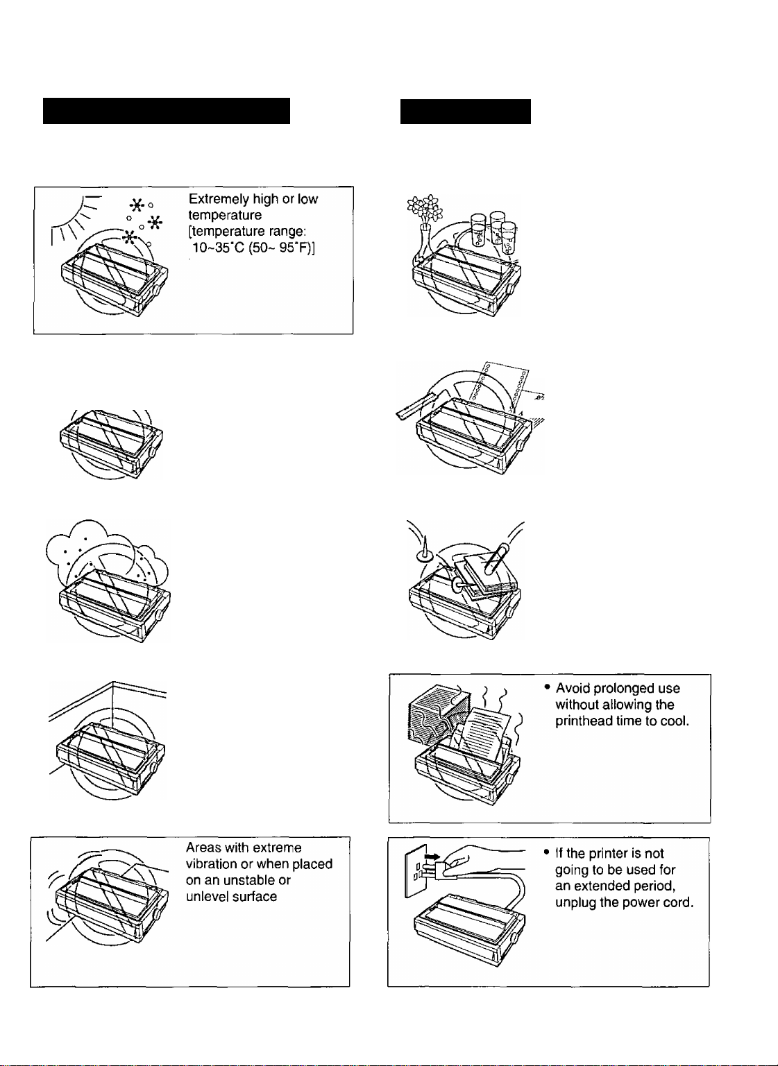
Do not use the printer in the following conditions.
A A A A A Extremely high or low
6^0 6^ humidity
A A^A'^A A (humidity range:
^ ^ On_ QAO/ DU\
20-80% RH)
Precautions
Thefollowing precautions are recommended to extend
the life of the printer.
Keep all liquids away
from the printer
— Accidental spillage
of a liquid into the
printer can cause
severe damage.
• Do not operate the
printer without paper
and a ribbon cassette
W installed.
Areas of high dust
concentration
Areas of poor ventilation
[a minimum of
4" (10 cm) clearance on
all sides is necessary to
insure proper ventilation]
Do not place books,
paper, or other items
on top of the printer.
Do not obstruct the
movement of the
printhead while in
operation.
Page 6
CO
Q>
0
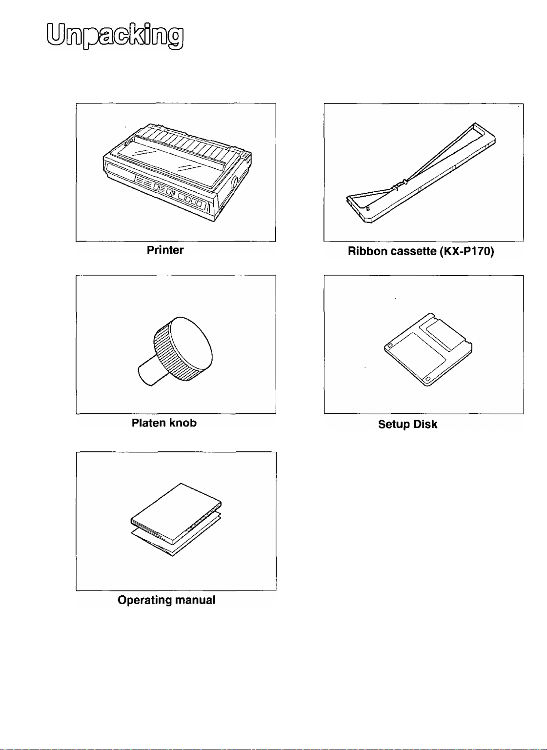
Having unpacked the printer, make sure none of the contents shown below are missing or damaged.
Report damages or shortages to the store from which the unit was purchased.
f
------------------------------------------------------------
• The Setup Disk contains a Printer
Driver for Windows Ver. 3.1 (P.
27), a Setup program ( P. 28)
and a Command Reference
program ( P. 52).
• To use this Setup Disk, you need to
have an IBM-PC or a compatible
computer with a 3.5'' floppy disk
drive.
Quick start guide
Note:
• It is recommended that you save the original carton and packing materials for proper shipping and
transporting of the printer.
N
Page 7
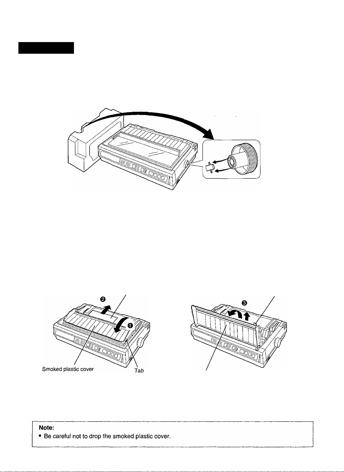
Preparation
(a) Insert the platen knob into the hole on the right side of the printer and rotate it slowly until it slips onto
the shaft. Push the platen knob onto the platen shaft to secure.
m
(D
o
<D.
-<
O
c
CO
fia
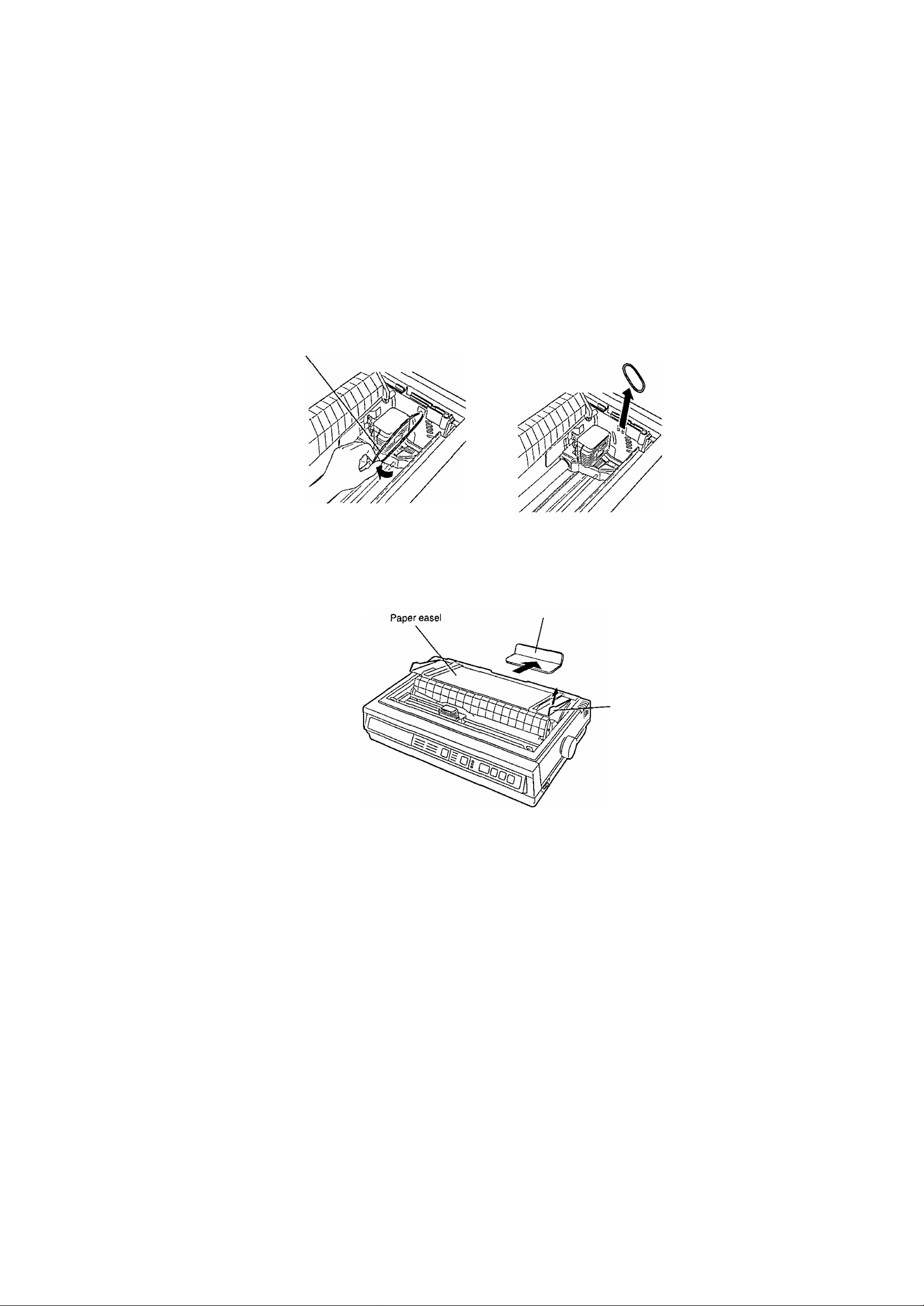
(b) O Fold forward the smoked plastic cover.
© Remove the protective paper which includes unpacking instructions.
© Raise the smoked plastic cover and remove it.
Protective paper
Smoked plastic cover
Tab
Page 8
(c) Remove the carriage stopper band, as shown,
Carnage stopper band
(d) Remove the separator pad lifting the paper easel by holding the tab of it
Separator pad
Tab
r Note:
•
I
• Be sure to replace the carriage stopper band and the separator pad before transporting the printer
8
Page 9
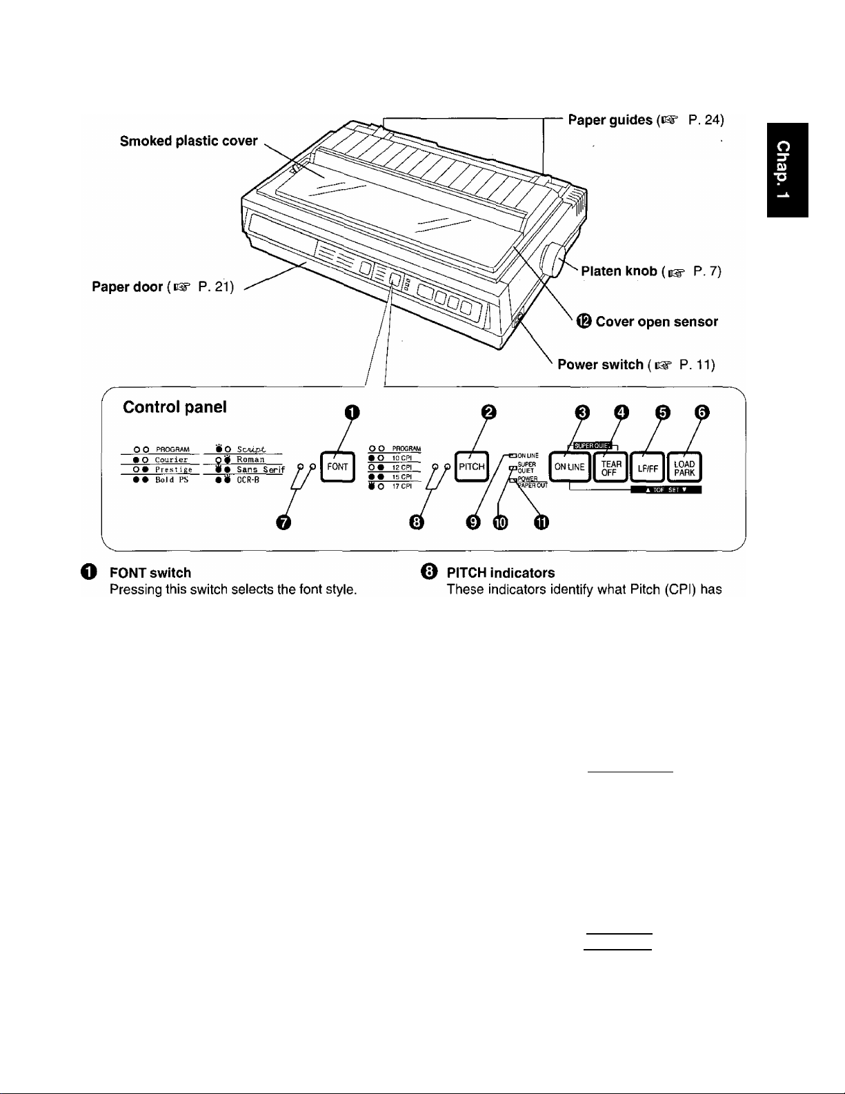
1®= p. 40)
e PITCH switch
Pressing this switch selects the characters per
inch (cpi). (P. 40)
0
ON LINE switch
This switch opens and closes the
communication line with the computer.
O TEAR OFF switch
Pressing this switch advances or reverses the
paper for tearing off. { P. 44)
© LF/FF switch
Pressing this switch advances the paper one
line at a time. Holding this switch advances the
paper to the first print line of the next page.
{P. 42)
0
LOAD/PARK switch
Pressing this switch loads or parks the paper.
(P. 45)
O FONT indicators
These indicators identify which Font has been
selected. (P. 40)
been selected. {eg* P. 40)
0
ON LINE indicator
This indicator is lit when the printer is in the ON
LINE mode, and is not lit when in the OFF LINE
mode.
® SUPER QUIET indicator
This indicator is lit when the printer is in the
SUPER QUIET mode. (While pressing the ON
LINE switch, press the [ TEAFVOFF] switch.)
{ ^ P. 41)
0 POWER/PAPER OUT indicator
This indicator is lit when the power is on and
paper is installed. It blinks when paper is not
installed. (P. 46)
0
Cover open sensor
When the cover is opened, the machine will
beep and printing will stop. To resume printing
close cover and press [ ON LINE].
Page 10
CD
(D
O
(D
-<
O
c
c/>
D)
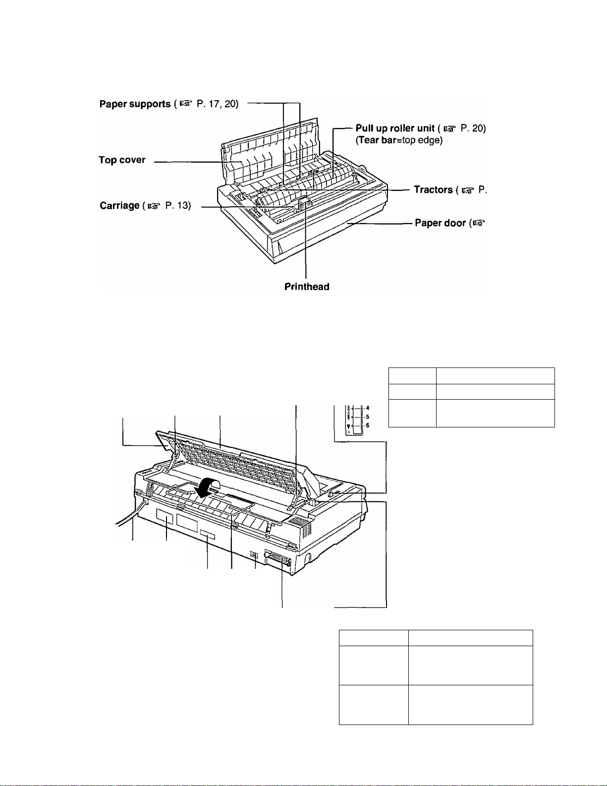
Paper easel
{i^ P. 18,23)
Rear supports (cs" P. 18)
________\__________
Paper easel hand
guide (eg* P. 18, 23)
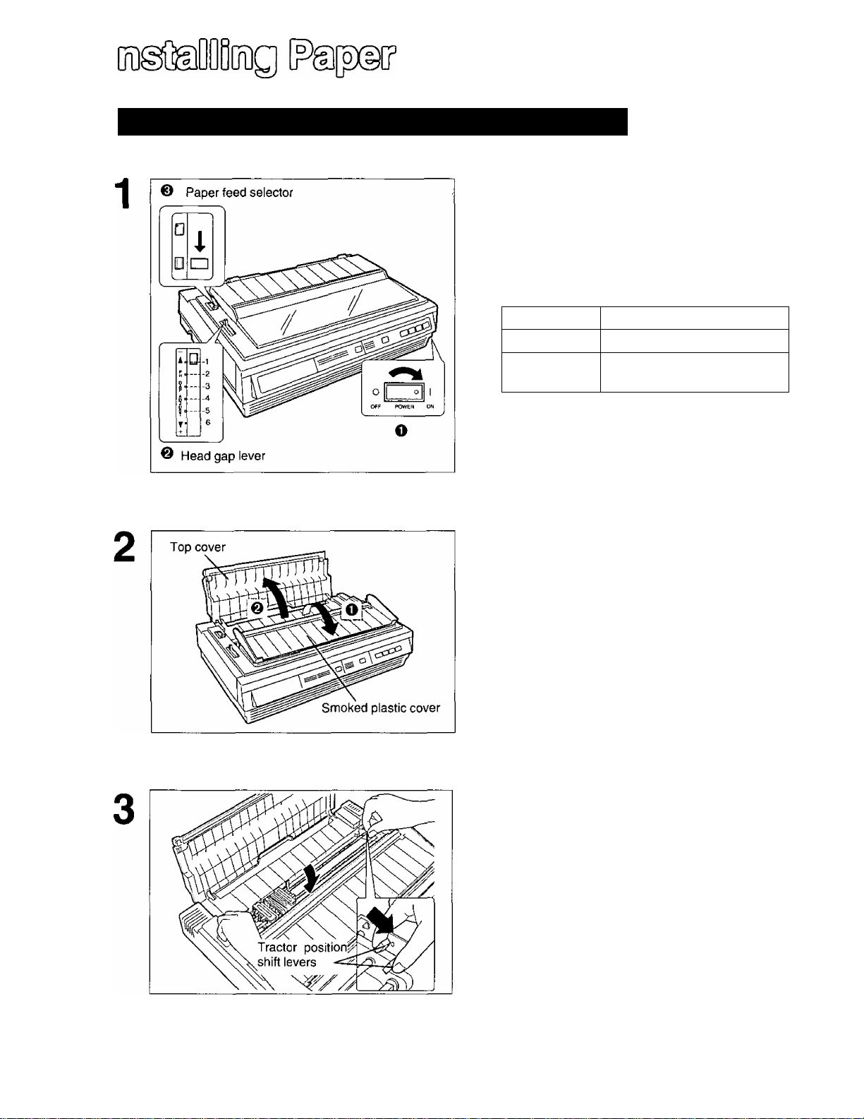
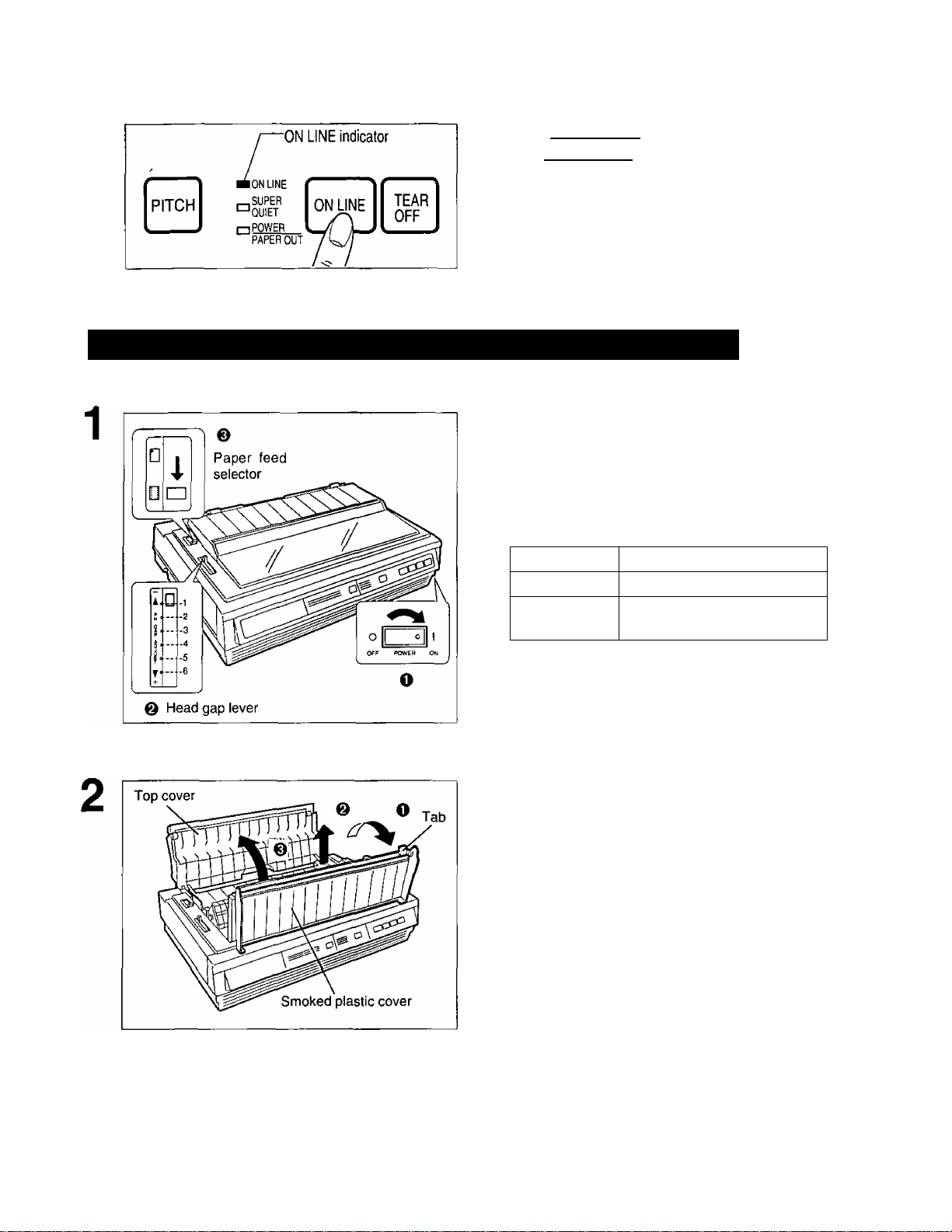
Head gap lever
Adjusts the gap between the platen and the
printhead. The lever moves in increments of
0.0028 inch (0.07 mm).
■Q-
Position
1 or 2
3, 4,5
or 6
Thinner sheets
Thick sheets, multi-part
forms or envelopes
Used for
AC power cord
(C3= P. 11)
Nameplate
Serial No. label *
Paper separator ( eg* P.18)
Frame ground terminal
(P. 11)
Centronics parallel interface
connector {P. 11)
* For units sold in Canada, Serial No. is located
on the Nameplate.
10
Paper feed selector
Position Used for
Q (Friction)
[H] (Tractor)
Single sheets and
envelopes
Fanfold paper (Front,
bottom and rear feeding)
Page 11
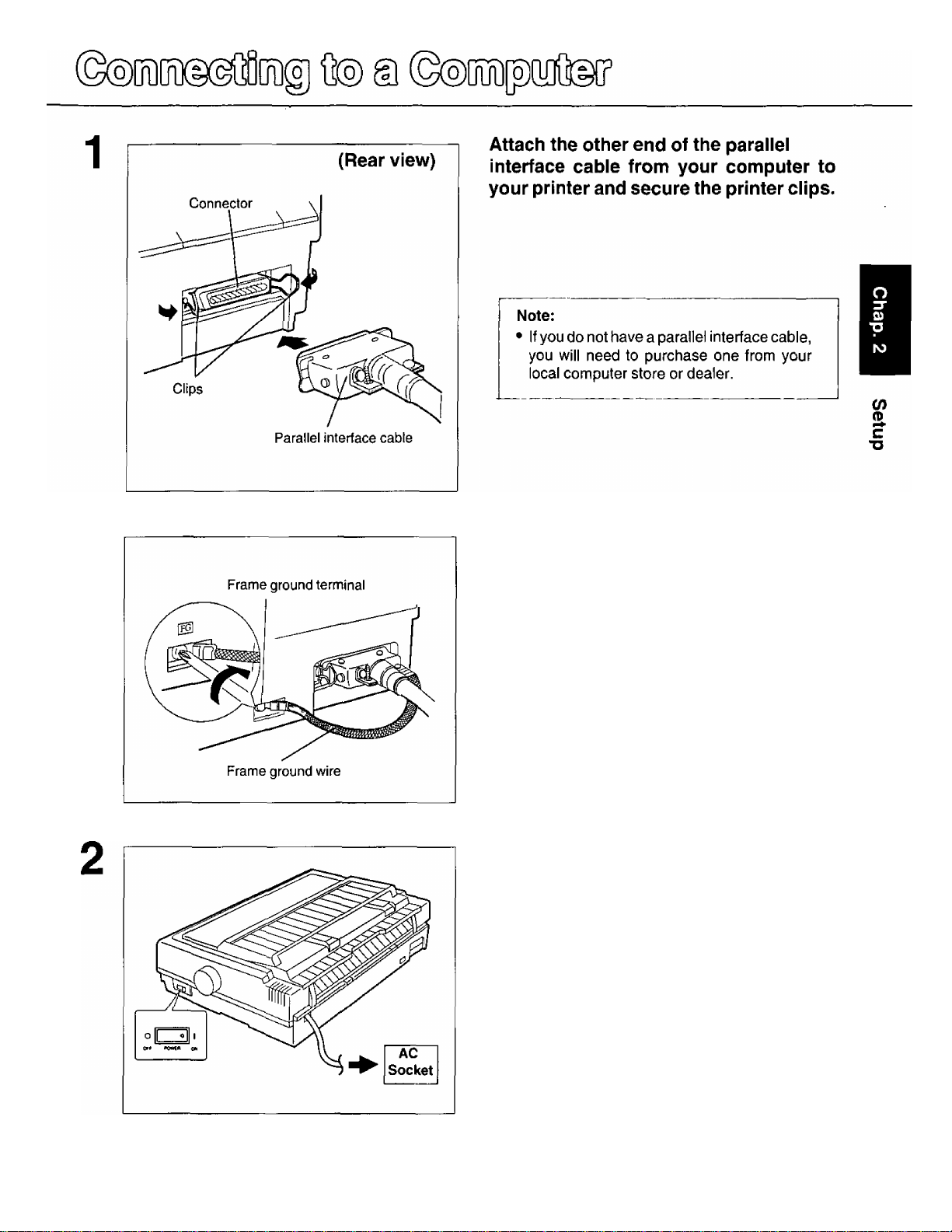
If the cable has a frame ground wire,
connect it to the frame ground terminal.
Plug printer into a grounded 3 prong AC
socket.
When the power is supplied to the printer, the power
indicator on the control panel will light.
11
Page 12
O)
(D
c
■O
!^0№)®(iì) ©agsMìife
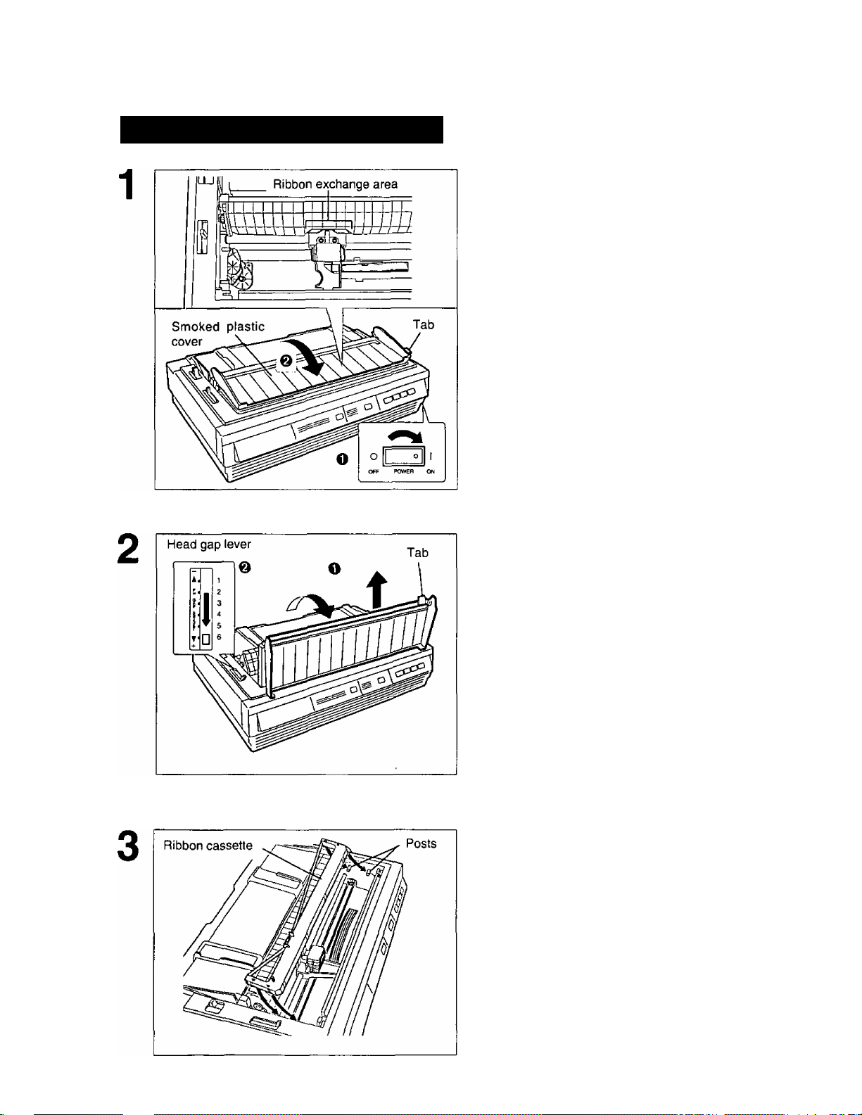
Installing the Ribbon Cassette
O Turn the power on.
The carriage will automatically move to the ribbon
exchange area.
I Note:
! • The ribbon cassette can only be installed in
! this area.
O Fold forward the smoked plastic
cover.
O Raise the smoked plastic cover and
remove it.
0 Move the head gap lever to the (+)
position.
Note:
• Be careful not to drop the smoked plastic
cover.
• The printhead may be hot, use caution when
cover is open.
1
__
Lower the ribbon cassette onto the four
ribbon posts (gold in color), insert the
back portion of the ribbon into the printer
first.
12
Page 13
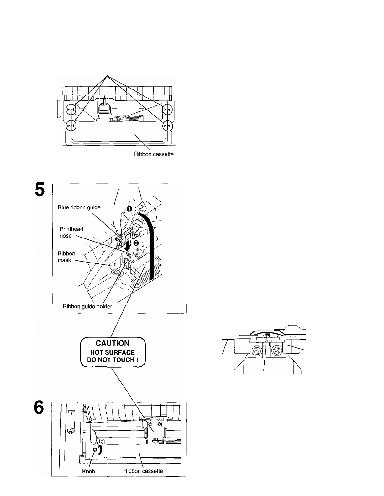
Arrows
Line up the 4 arrows on the ribbon
cassette with the arrows on the left and
right sides of the frame. Push 4 arrows
down until they click into place.
Note;
• Make sure that the ribbon cassette is
perfectly placed in position.
O Grasp the top of the blue ribbon guide
with your thumb and forefinger,
remove the blue ribbon guide by lifting
from the ribbon cassette.
@ Slide the blue ribbon guide onto the
ribbon guide holder of the carriage
and push the blue ribbon guide down.
C/)
(D
Note:
• If the ribbon does not insert easily between
the printhead nose and the ribbon mask
rotate the knob to reduce slack.
Top view
Ribbon
Ribbon mask
Blue ribbon
guide
Printhead nose
Rotate the knob on the ribbon cassette
counterclockwise to remove any slack.
13
Page 14
CO
(D
C
■O
SïïÈÈxaîo ©a@g3GS§
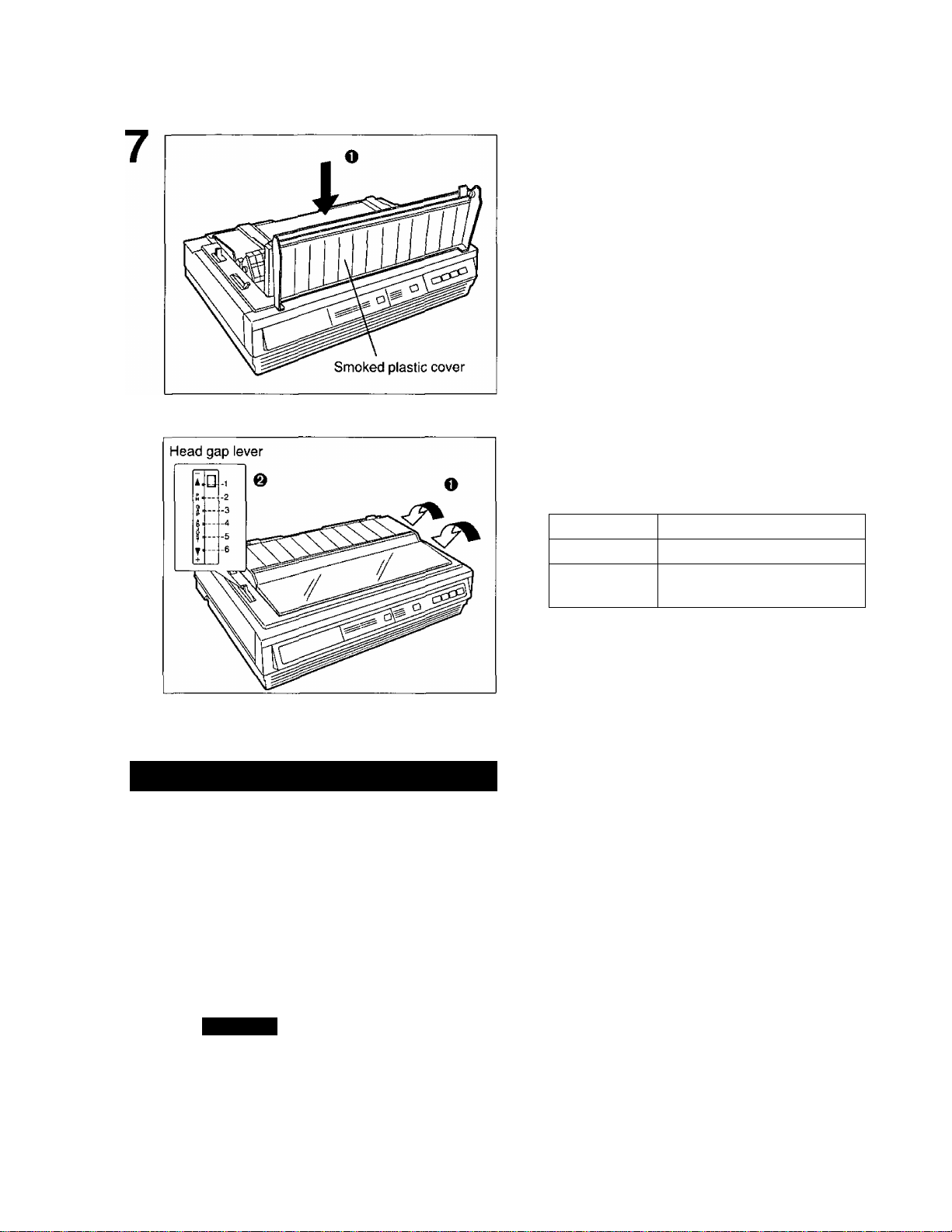
0 Replace the smoked plastic cover
O Adjust the head gap lever for the
thickness of paper you are using.
Position
1 or 2 Thinner sheets
3, 4, 5 or 6
Thick sheets, multi-part
forms or envelopes
Used for
Removing the Ribbon Cassette
To remove the ribbon cassette, perform step 1-2 of “Installing the Ribbon
1
Cassette” at first. ( P.12)
Then reverse the installation procedure, (step 5 step 4 step 3 of “Installing
the Ribbon Cassette”. (P. 12~13)
14
Caution:
• The printhead may be hot, use caution when cover is open.
• Do not lift up the flat cable located under the carriage when removing the ribbon cassette. It may
break off.
Page 15
0
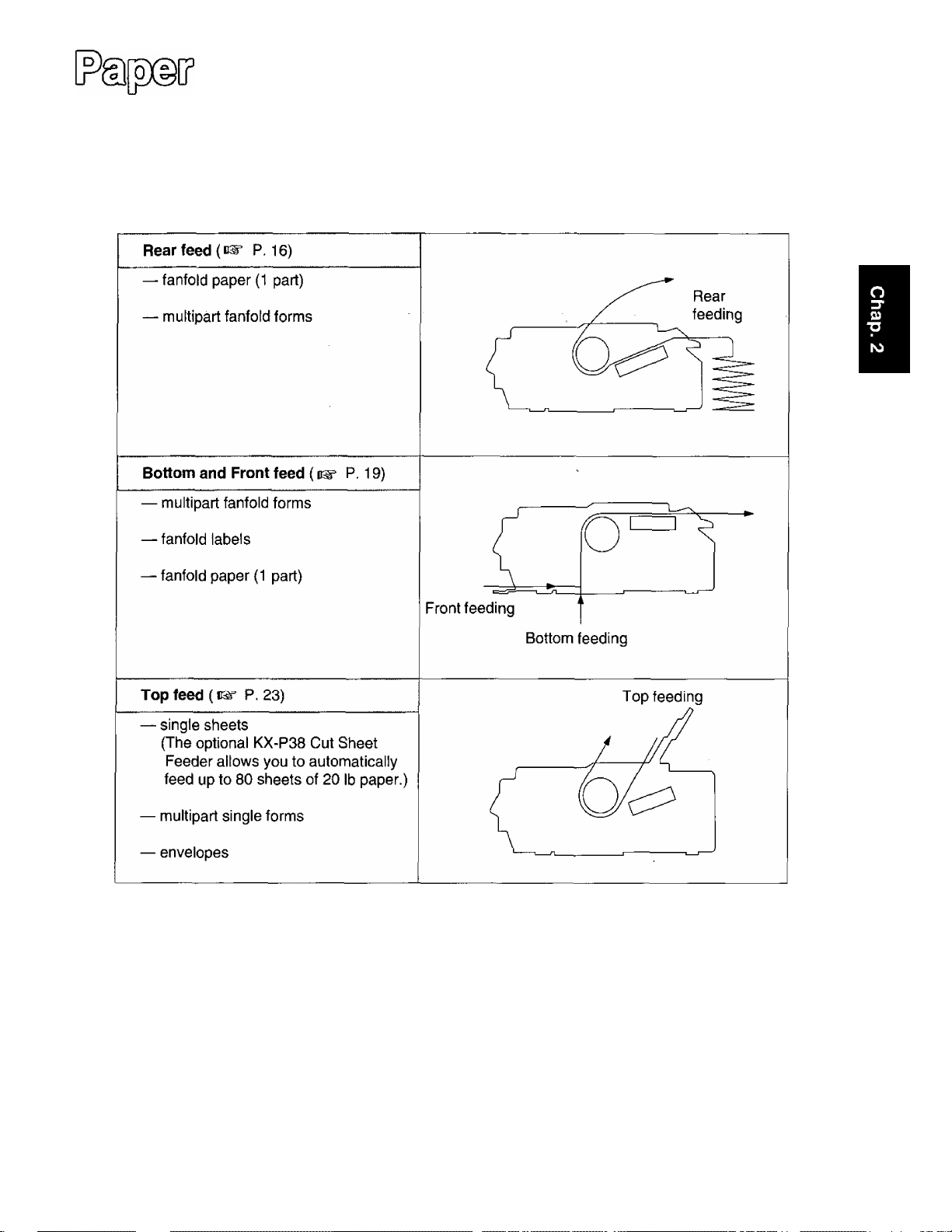
This printer supports 4 paper paths (rear, bottom, front and top feeding). Rear, bottom and front
feedings are for continuously fed" paper. Top feeding is for single sheets or envelopes.
The optional KX-P38 Cut Sheet Feeder will accommodate automatic feeding of up to 80 single sheets
from the top paper path.
©©20®[ji]
0)
(D
Note:
• For optimum print quality, do not use reverse line feeding in bottom and front feeding. If reverse
feeding is necessary in bottom and front feeding, set REVERSE LF/PULL in the INSTALL menu
to ON by using the Setup Disk.
• Paper Parking is not available in bottom and front feeding.
• When using multipart fanfold paper especially in environments that have very high or low
temperature and/or humidity, we recommend the use of the bottom feed pull mode to optimize
paper handling and print quality.
15
Page 16
o
Fanfold Paper: (Rear Feed/Push Tractor Mode)
O Turn the power on.
The PAPER OUT indicator will flash indicating
that paper is not installed in the printer.
O Adjust the head gap lever for the
thickness of paper you are using.
Ü)
(D
C
■o
Position
1 or 2
3, 4, 5 or 6
Thinner sheets
Thick sheets or multi-part
forms sheets
Used for
© Set the paper feed selector to
“ p ” (Tractor Mode).
O Fold forward the smoked plastic
cover.
© Open the top cover.
16
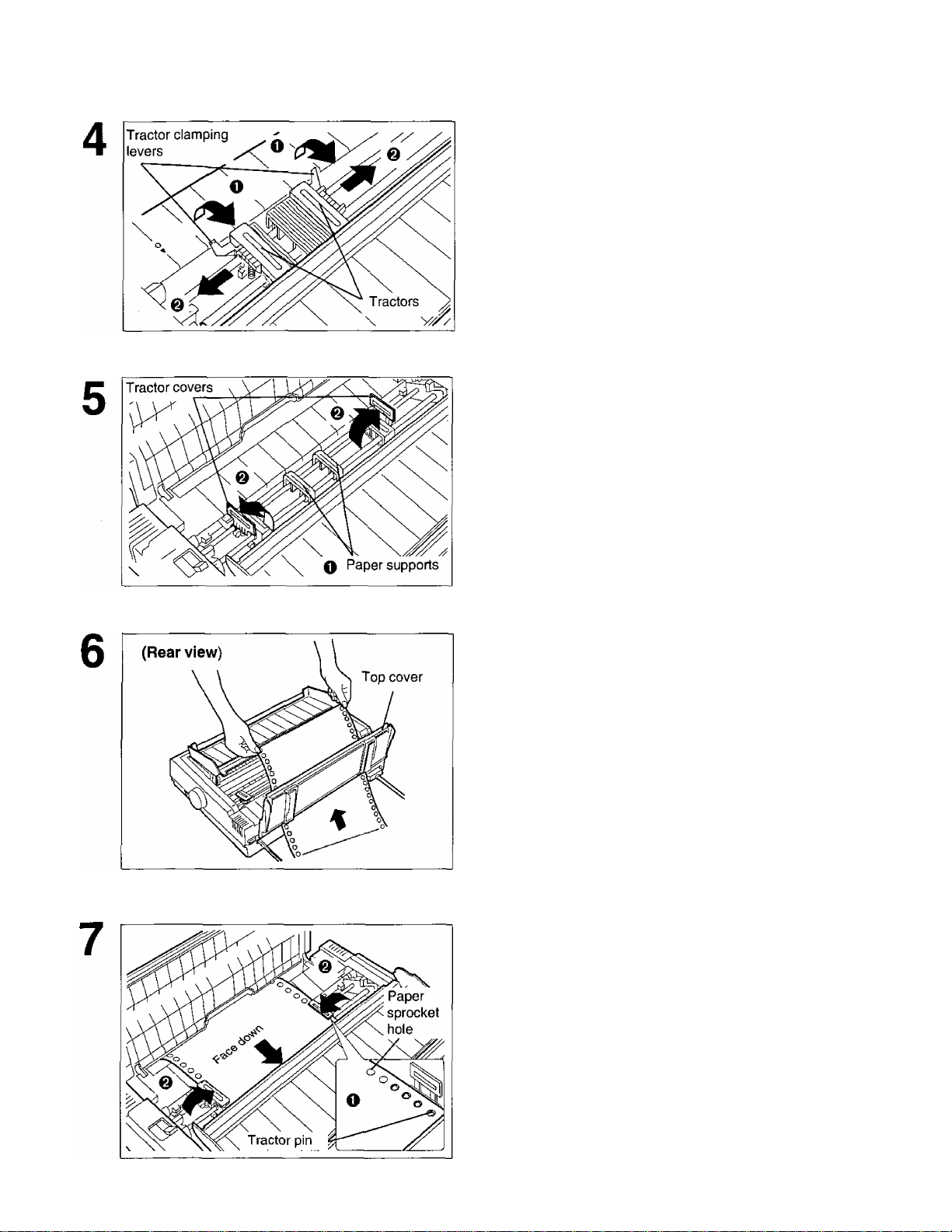
Pinch both left and right tractor position
shift levers and lower the tractor
mechanism downward until the tractors
fall into place, then release.
Page 17
ODDSíMBji©
0 Unlock the tractors by pulling the
tractor clamping ievers forward.
@ Siide the tractors to accommodate the
approximate width of the paper being
used.
In most applications, you will find that the “0”
indicator on the tear bar is a useful tool for
predeterrnining your left most print position.
O Slide the two paper supports between
the tractors at equal spaces.
© Open the tractor covers.
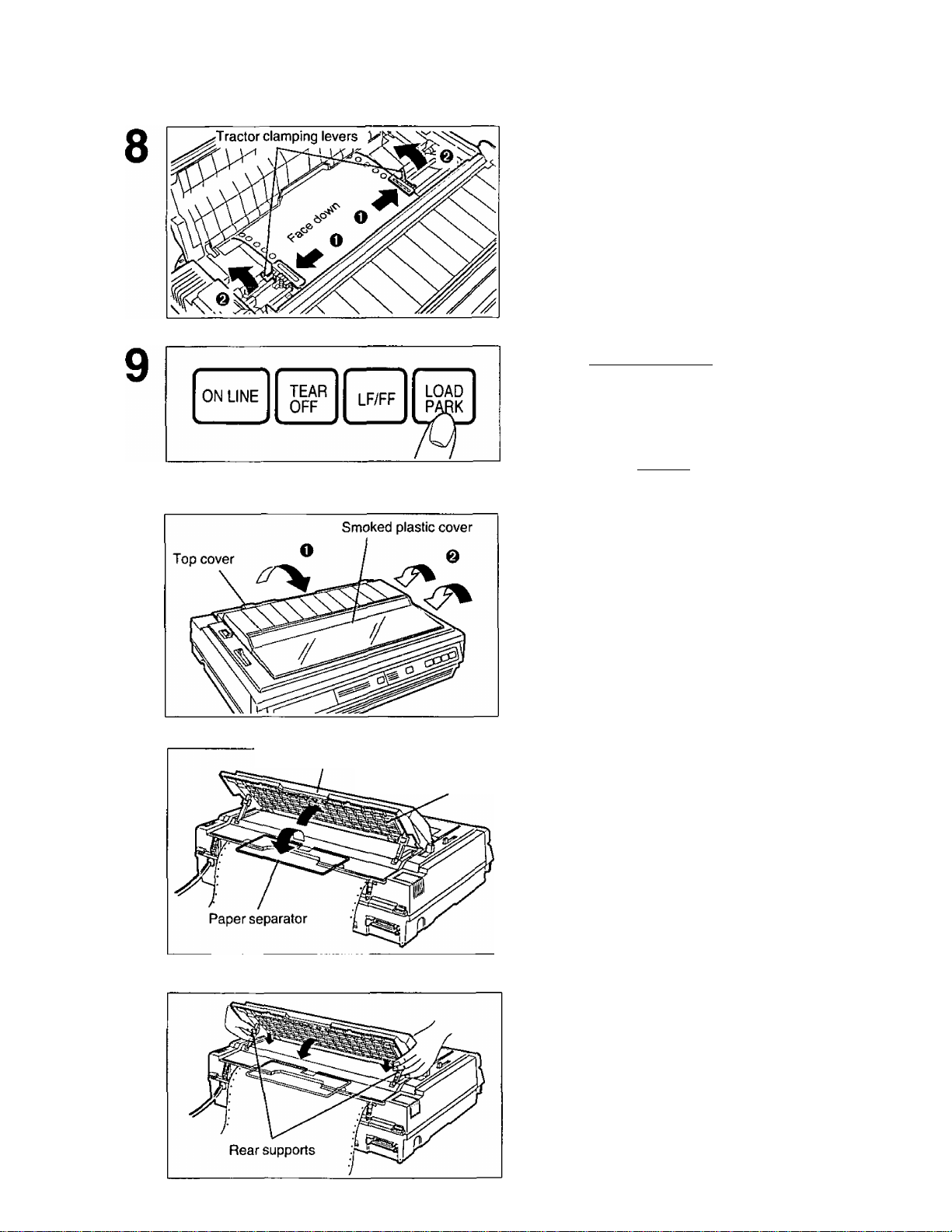
Feed paper through opening between
printer and the top cover.
CO
(D
C
■O
O Align the paper sprocket holes with
the tractor pins, making sure the
paper is straight.
© Ciose the tractor covers.
17
Page 18
ttMMBDDg]
O Adjust the tractors to remove any
slack in the paper.
@ Lock the tractors by pushing the
tractor clamping levers back.
r Note:
Put the tractor pins in the center of the paper
sprocket holes when locking.
Press (LOAD/PARK).
CO
(D
10
11
Paper easel hand guide
Paper easel
This will load the paper to the first print line.
Note:
• Do not use (LF/FF) to load paper.
O Close the top cover.
0 Fold back the smoked plastic cover.
Extend the paper separator by first
raising the paper easel by lifting the
paper easel hand guide and then
unfolding it.
12
18
Lower the paper easel by simultaneously
depressing the rear supports.
Note:
• Be careful not to pinch your fingers.
• When in tractor mode please do not use
paper guides to guide the paper path. In
tractor mode the paper is guided by the
tractor units themselves.
Page 19
ODOgL^DOoog) [?fe(?e(F
13
press (ON LINE] to get ready to print.
r'
Note:
• If setting up the printer for the first time,
proceed to Printer Driver Selection.
(B^ P.26)
Fanfold Paper: (Bottom, Front Feed/Pull Tractor Mode)
O Turn the power on.
The PAPER OUT indicator will flash indicating
that paper is not installed in the printer.
@ Adjust the head gap lever for the
thickness of paper you are using.
Position
1 or 2 Thinner sheets
3, 4, 5 or 6
If ON LINE indicator is not lit,
Used for
Thick sheets or multi-part
forms sheets
CO
(D
C
■O
0 Set the paper feed selector to
“ [Til ” (Tractor Mode).
O Fold forward the smoked plastic cover
and raise it.
0 Remove the smoked plastic cover.
© Open the top cover.
19
Page 20
(/)
(D
ODDSiMBODg] [?^][^
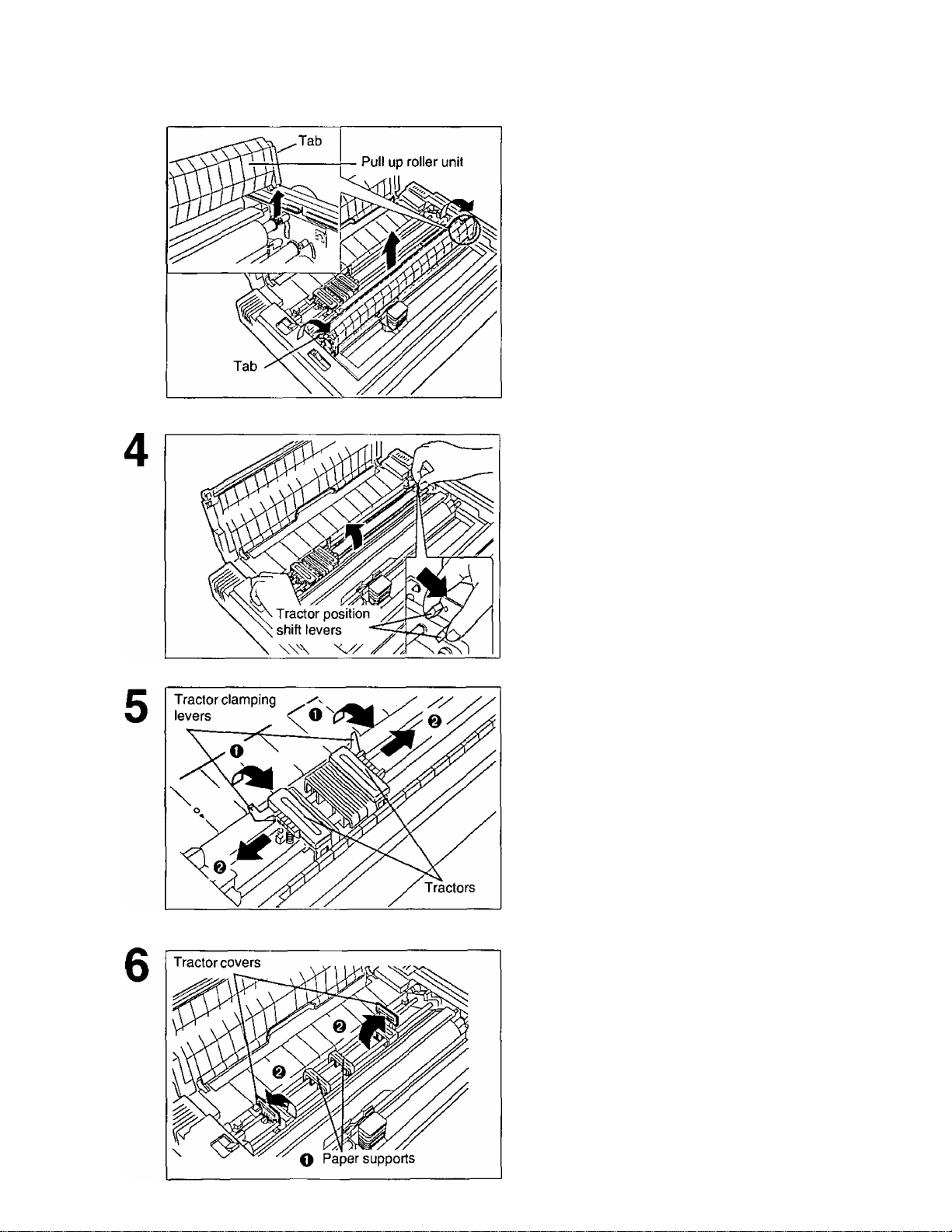
Remove the pull up roller unit by gently
rotating forward using the tab until you
feel it release, then lift up.
Note:
• Do not misplace the pull up roller unit.
Pinch both left and right tractor position
shift levers, and lift the tractor
mechanism up then release the levers.
O Unlock the tractors by pulling the
tractor clamping levers forward.
O Slide the tractors to accommodate the
approximate width of the paper being
used.
In most applications, you will find that the “0”
indicator on the back of the cover is a useful tool
for predetermining your left most print position.
O Slide the two paper supports between
the tractors at equal spaces.
O Open the tractor covers.
20
Page 21
0DD@[yD0OD® (?fe(óXiCP
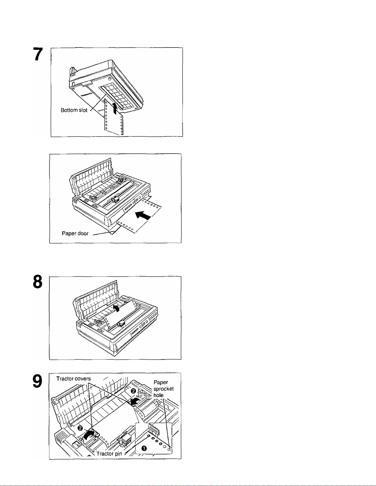
When Bottom Feeding:
With the printer being supported by a
printer stand, or on a table that allows for
bottom feed, push the paper up through
the bottom opening until it appears in
front of the platen.
When Front Feeding:
Open the paper door and insert the paper
until it appears in front of the platen.
Note;
• When feeding fanfold paper or lables
through the front paper door, paper types
and condition, as well as temperature and
humidity conditions may effect accurate line
feeding and print quality may not be
optimum. For optimum output bottom feed is
recommended.
Adjust the paper position by pulling it up
as shown.
cn
(D
c
T3
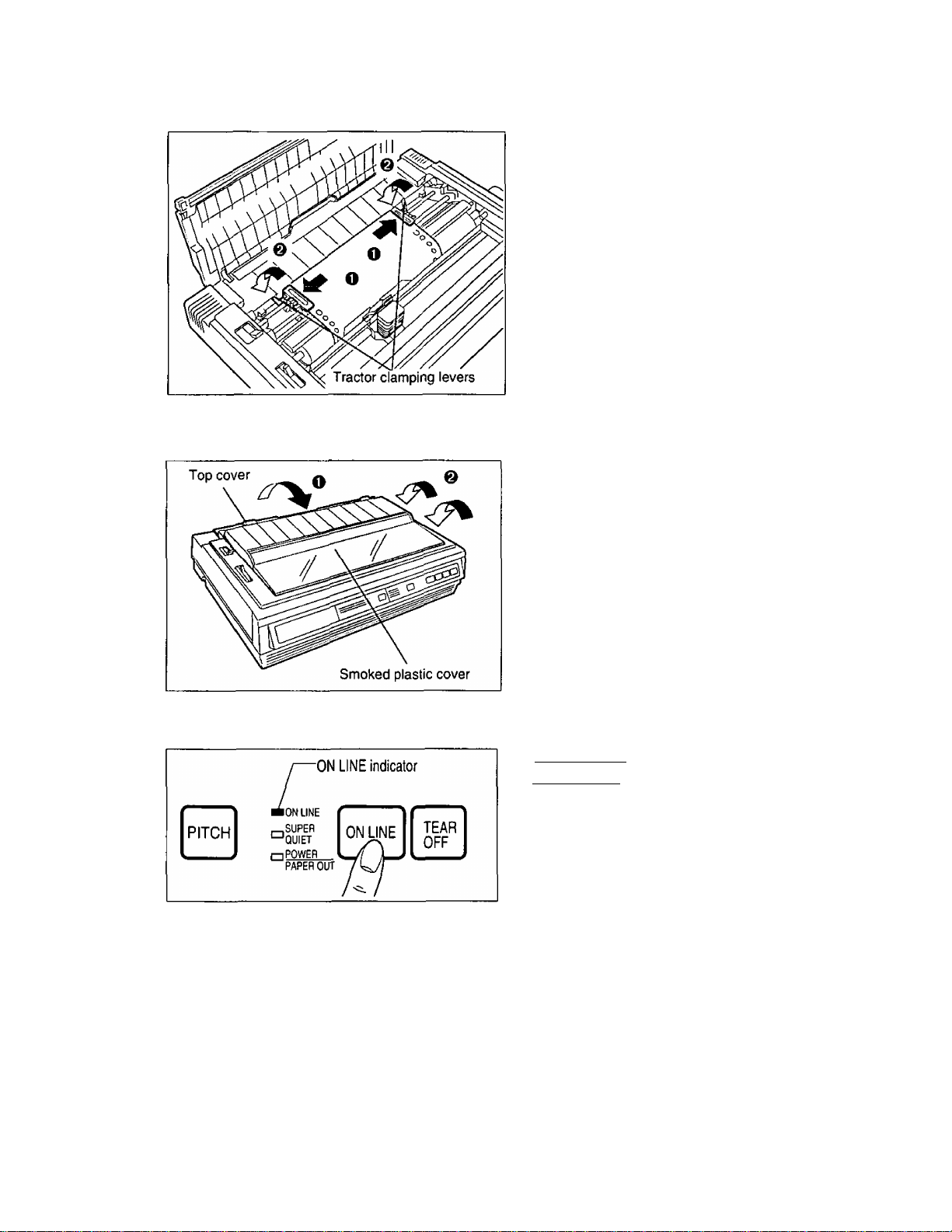
O Align the paper sprocket holes with
the tractor pins, making sure the
paper Is straight.
@ Close the tractor covers.
21
Page 22
O)
(D
C
■O
10
11
O Adjust the tractors to remove any
slack in the paper.
O Lock the tractors by pushing the
tractor clamping levers back.
Note:
• Put the tractor pins in the center of the paper
sprocket holes when locking.
O Close the top cover.
& Replace the smoked plastic cover.
* •
12
22
If ON LINE indicator is not lit, press
[ON LINE) to get ready to print.
Note:
• If setting up the printer for the first time
proceed to Printer Driver Selection.
( P. 26)
Note:
• In bottom and front feed, reverse feed functions will not feed paper correctly and the resulting printout
may not be correct.
If reverse feeding is necessary in bottom or front feed, set REVERSE LF/PULL in the INSTALL
menu to ON by using the Setup Disk.
• When in tractor mode please do not use paper guides on the top cover to guide the paper. In tractor
mode the paper is guided by the tractor units themselves.
Page 23

Single Sheets and Envelopes: (Top Feed/Friction Mode)
O Turn the power on.
The PAPER OUT indicator will flash indicating
that no paper is installed in the printer.
& Adjust the head gap lever for the
thickness of paper you are using.
Position Used for
1 or 2 Thinner sheets
3, 4, 5 or 6
€) Set the paper feed selector to
“ Q ” (Friction Mode).
Thick sheets or envelopes
ODOSiMBDQg]
CO
(D
C
■Q
O Fold forward the smoked plastic
cover.
Q Raise the paper easel by lifting the
paper easel hand guide.
23
Page 24

ODDSifeflBODg)
O Separate the paper guides to the
approximate width of your paper or
envelope.
0)
(D
C
■O
Note:
• To predetermine your left most print
position, move the left paper guide until it
clicks into place. |
@ Insert a sheet of paper through the
paper guides.
The paper will automatically be loaded to the first
print position.
Note:
• To disable Auto Loading, turn it OFF in the
Install Menu on your Setup Disk.
{ ^ P. 30)
• If Auto Loading is disabled, you must
press [ LOAD/PARK1 to load paper.
• If you need to align the paper horizontally or
vertically, set the paper feed selector to
“ i".
This releases the paper and allows the
paper to be positioned manually as
required. Set the-selector back to “ Q ”
before printing.
1
Fold back the smoked plastic cover.
If ON LINE indicator is not lit, press
[ ON LINE ] to get ready to print.
Note:
• If setting up the printer for the first time,
proceed to Printer Driver Selection.
{ 1®= P. 26)
Note: ^
• When the paper feed selector is in “ o ”, the buzzer will sound to inform you that the selector is in
the wrong position. ^ j
• When loading an envelope, if the envelope will not load smoothly, move the paper feed selector to '
“ jyj ” and insert the envelope manually, then move the selector back to “ Q ”. ;
* •
I
24
Page 25

The printer has a self test feature which allows you to test the printer. When activated, this feature will
print 5 lines of each resident font. When complete, it will return to the draft font and continue
approximately 20 minutes.
Load fanfold paper or a single sheet
of paper, then turn the power off
I
p. 16-24).
While pressing [ LF/FF ) , turn the power
on, then release.
0)
(D
C
“O
Version
Draft
! ’( ./0123456789
! "#$%&’( )*+,”./0123456789:
’( ./0123456789: ;
./0123456789: ; <
$%&’( )*+ ./0123456789: ;
Courier
!"#$%&’()*+,-./0123456789
!”#$%&’()*+.-./0123456789:
"#$%&'()*+,-./0123456789:;
#$%&'()*+,-./0123456789: ;<
$%&*()*+,-./0123456789: ;< =
Prestige
/0123456789
! '()*+,- ./0123456789 :
’()*+,-./0123456789 ; :
: ; < = >?@ABCDEFGHIJKLMNOPQRSTL
; < = >?@ABCDEFGHIJKLMNOPQRSTUV
<=>?@ABCDEFGHIJKLMNOPQRSTUVU
^>?@ABCDEFGHIJKLMNOPQRSTUVW>
> ?@ABCDEFGHI JKLMNOPQRSTUVWX'f
: ;< = >?@ABCDEFGHIJKLMNOPQRSTt
;<=>?@ABCDEFGHIJKLMNOPQRSTUX
< = >?@ABCDEFGHIJKLMNOPQRSTUVV
= >?@ABCDEFGHIJKLMNOPQRSTUVW)
>?@ABCDEFGHIJKLMNOPQRSTUVWX^
::<=>?@ABCDEFGHIJKLMNOPQRSTl
:<=>?@ABCDEFGHIJKLMNOPQRSTU\
<=>?@ABCDEFGHIJKLMNOPQRSTUVV
=>?@ABCDEFGHIJKLMNOPQRSTUVW)
Once you see that the printer is
functioning properly, you may turn
the power ofif during the self test, or
you may run the entire test.
(Approximately 20 minutes)
ABODEFGHIJKLMNOPQRSTUVWX
25
Page 26

0)
<D
C
T3
The printer driver allows your application software to properly control your printer’s features. The printer
driver is contained in your application software.
Selecting a printer driver is the final step before printing and is performed in your application software
program. The steps will vary, depending on the software program. Consult your software package for
proper procedures. The Panasonic KX-P3626 will be your first choice. However, if the Panasonic
KX-P3626 printer is not listed in your software, you must select an alternative from the following table.
Note: If using Microsoft Windows Version 3.1, you will need to install a Windows printer driver. This
driver is located on the Setup Disk supplied with your printer. Proceed to Installing a Printer
Driver section on page 27 for the installation procedure.
Printer Driver Seiections (in order of priority)
Printer Seiections
Panasonic KX-P3626
Panasonic KX-P3624
Epson LQ-1170 (ESC/P2TM)
Panasonic KX-P3123/3124
Panasonic KX-P2624
Epson LQ series
IBM Proprinter XL24E*
If selecting the IBM Proprinter XL24E in your software, printer emulation must also be changed in
the Initial Setup items, (c^ P. 28-39, 47-49)
26
Page 27

P/0lM)SS55© W@(?o ®bU))
The following steps are only necessary if using Microsoft Windows Version 3.1. The Setup Disk
packaged with your printer contains a Panasonic KX-P3626 Printer Driver for Windows Version 3.1.
To install this printer driver, you must begin at the Program Manager screen in your Windows program.
Follow the steps below for the proper installation procedure.
Note;
• Use the DISKCOPY command of the operating system to make a back-up copy. Refer to your DOS
manual for further information.
In “Main Group”, select “Control
1
Panel”.
In “Control Panel”, select
“Printers”.
If you have installed a printer driver, the
dialog box expands to display a list of
printers available in the Windows Ver. 3.1
package, and I Add>:T| is unavailable. In
“Installed Printers”, select the printer you
want. Go to step 9.
Click Add»
Printers
Default Printer —
xxxxxxxxxxxxxx
Installed Printers:
xxxxxxxxxxx
Set As Default Printer
I Cancel I
j Connect... [
[ Setup... 1
Remove
Add »
Help
Click OK .
Install-Driver
Insert unlisted, updated, or
vendor-provided printer driver disk in:
A:\
[ Cancel I
I Browse... 1
I Help I
The printer driver KX-P3626 is shown in
the dialog box.
Click OK
8
Add Unlisted or Updated Printer
List of Printers:
Panasonic KX-P3626
OK
OK
Cancel
^ * <D
---
1
In “List of Printers”, select
“Install Unlisted or Updated
Printer”.
Click Install...
5
Insert the Setup Disk into drive
6
A.
If reading the printer driver disk from drive
B, type B:\
Help
Click Set As Default Printer
9
10 Click I Close
11 Exit the “Control Panel”.
27
Page 28

roMaO
This printer allows you to select 48 initial setup items shown in the table below. You can select all
these items by using the Setup Disk.
C
S2.
5'
(O
(D
0)
o
c
T3
D
w'
7T
Menu
PRINT STYLE
EMULATION
PAGE
FORMAT
Item
FONT Draft*
Bold PS
Courier
OCR-B
Prestige
Roman
Sans Serif
Script
PITCH 10 CPI*
12 CPI 5 CPI
15 CPI
17 CPI
20 CPI
POINT SIZE
[displayed only
when -SC
sequences are
selected in Font.
EMULATION
LINE/INCH
PAGE LENGTH
TOP MARGIN
BOTTOM
MARGIN
LEFT MARGIN
RIGHT MARGIN
CTR PRINTHEAD
(Centering
printhead)
10.5* (8 to 96) Point
EPSON*
IBM
1 LPI 4 LPI 8 LPI
1.5 LPI 4.5 LPI 9 LPI
2 LPI 5 LPI 10 LPI
2.5 LPI 6 LPI* 12 LPI
3LPI 7.5 LPI Scalable
14 inch
12 inch
11^ inch
11 inch*
0.00"* to 2.50"
(0.00 cm to 6.35 cm)
0.00"* to 5.00"
(0.00 cm to 12.70 cm)
0* to 134 column (10 CPI)
2 to 136* column (10 CPI)
42* (10 to 80) column (10 CPI)
Setting
Super LQ
Bold PS-SC
Courier-SC
Prestige-SC
Roman-SC
Sans Serif-SC
Script'SC
PROPORTIONAL
6 CPI
7.5 CPI
8.5 CPI
8.5 inch
8 inch
5.5 inch
FREE
Description
Selects Draft, LQ (Letter
Quality), SLQ (Super Letter
Quality) or SC (Scalable).
Selects the desired
characters per inch (cpi) or
Proportional Spacing.
The number increases or
decreases by 2 (plus 10.5
and 21).
Sets the emulation mode to
Epson LQ-1170 or IBM
Proprinter XL24E.
Selects the desired lines per
inch (cpi).
“Scalable” can be set only
when a SC FONT is selected
in the FONT Setting.
When you select “FREE”, the
number increases or
decreases by W' from 0.5"
to 15.0".
The number increases or
decreases by W' (about
0.35 mm).
The number increases or
decreases by i/72" (about
0.35 mm).
The value number depends
on the PITCH and PRINT
WIDTH selected.
The value number depends
on the PITCH and PRINT
WIDTH selected.
The number increases or
decreases by 1.
28
* denotes setting when shipped from factory.
Page 29

lifiSI
§@QDq^ (l®c33
Menu
PRINT MODE GRAPHIC
DIRECTION
TEXT DIRECTION Bl DIRECTION*
PRINT WIDTH
TEXT
ENHANCEMENT
CHARACTER
SET
BOLD (determines
weight or thickness of
a character)
DOUBLE HIGH
(height of a character
is twice that of a
normal one)
DOUBLE STRIKE
(two passes of the
printhead)
DOUBLE WIDE
(width of a character
is twice that of a
normal one)
ITALICS
OUTLINE OFF*
SHADOW
ZERO FONT
COUNTRY U.S.A.*
CHARACTER
SET
CODE PAGE
Item Setting Description
B1 DIRECTION
UNI DIRECTION*
UNI DIRECTION
13.6 inch*
8.0 inch
OFF*
ON
OFF*
ON
OFF*
ON
OFF*
ON
OFF*
ON
ON
OFF*
ON
NORMAL*
POINT
SLASH
JAPAN
FRANCE
GERMANY
U.K. (England)
DENMARK 1
SWEDEN
ITALY
SPAIN 1
ITALIC*
GRAPHIC 1
GRAPHIC 2
U.S.A.*
MULTILINGUAL
PORTUGAL
CANADA FRENCH
NORWAY
DENMARK 2
SPAIN 2
L.AMERICA
(Latin America)
KOREA
LEGAL
NORWAY
TURKEY
Graphics are printed left-to-right
only (UNI DIRECTION) or in both
directions (Bl DIRECTION).
Text is printed left-to-right only
(UNI DIRECTION) or in both
directions (Bl DIRECTION).
Selects the desired print width.
Activates bold printing (ON),
deactivates bold printing (OFF).
Activates double high printing
(ON), deactivates double high
printing (OFF).
Activates double strike printing
(ON), deactivates double strike
printing (OFF).
Activates double wide printing
(ON), deactivates double wide
printing (OFF).
Activates italic printing (ON),
deactivates italic printing (OFF).
Activates outline printing (ON),
deactivates outline printing
(OFF).
Activates shadow printing (ON),
deactivates shadow printing
(OFF).
Selects zero character
NORMAL (0), POINT (G) or
SLASH (0).
Selects one of 14 language or
legal character sets.
Selects the italics or
graphics/character sets 1 or 2.
(“ITALIC” is available only in
the Epson mode.)
Selects one of 6 code pages.
o
CO
<D
C
■a
V)
3T
* denotes setting when shipped from factory.
29
Page 30

Irntial
©san?) 0ÌÌM5
c
M
5'
(O
(D
CO
(D
C
TJ
(A
3T
Menu Item
INSTALL
AGM/IBM
AUTO CR/IBM OFF*
AUTO LF
BUZZER
AUTO LOADING OFF
PAPER OUT OFF
DETECT
SUPER QUIET
LF/PULL
TEAR OFF
CSF MODE
DOWNLOAD OFF*
AUTO ON LINE
(Alternate
Graphics Mode)
MODE
REVERSE
Setting
OFF*
ON
ON
OFF*
ON
OFF
ON*
ON*
ON*
OFF*
ON
OFF*
ON
MANUAL*
AUTO
OFF*
ON
ON
OFF
ON*
Description
Sets Alternate Graphics mode (selects
Epson graphics) to on or off in the IBM
mode. (This setting is effective only in the
IBM mode.)
Activates (ON) or deactivates (OFF)
Automatic CR on LF, VT, ESC+“J”.
(This setting is effective only in the IBM
mode.)
Activates (ON) or deactivates (OFF)
Automatic LF after CR.
Buzzer sounds (ON) or doesn’t sound (OFF).
Setting to ON automatically loads a single
sheet or envelope to the first print line.
[This setting is inoperative when using the
optional Cut Sheet Feeder (KX-P38)].
Paper Out Detector is active (ON) or ignored
(OFF).
Reduces (ON) or doesn’t reduce (OFF) the
printing noise.
Setting to ON enables the reverse feeding in
bottom and front feed.
When set to MANUAL, the paper’s
perforation doesn’t advance to the tear off
position unless you press the (TEAR OFFl.
Setting to AUTO advances the paper’s
perforation to the tear off position
automatically.
[This setting is operational when using the
optional Cut Sheet Feeder (KX-P38)].
Setting to ON allows you to download (userdefined) special characters and setting to
OFF allows you to send more data to your
printer’s buffer, thereby freeing up your
computer.
Setting to ON enables the printer to
automatically enter ON LINE mode after
installing paper.
30
denotes setting when shipped from factory.
Page 31

Initial
®gíц^WlsSs
Menu
INTERFACE
[The setting is
effective only
when the
optional
KX-PS14,
RS-232C
serial interface
board is
installed.]
T.O.F.
SETTING
(Top of Form
Setting)
Item ^
INTERFACE
DATA LENGTH
BAUD RATE +1
PARITY *1
PROTOCOL *1
SDT *1
RDT+1
SIGNAL
POLARITY *1
TRACTOR 0.00" to 5.00" (60/180"*)
FRICTION 0.00" to 5.00" (60/180"*)
CUT SHEET
FEEDER
PARALLEL*
SERIAL
8 BITS*
7 BITS
150 BPS 2400 BPS
300 BPS 4800 BPS
600 BPS 9600 BPS*
1200 BPS
NONE* ODD
IGNORE EVEN
DTR*
XON/OFF
RBC 128*
RBC 512
SDT+128*
SDT+256
MARK*
SPACE
(0.00 cm to 12.70 cm)
(0.00 cm to 12.70 cm)
0.00" to 5.00" (60/180"*)
(0.00 cm to 12.70 cm)
Setting
Description
Selects parallel interface or
serial interface.
Selects data length 8 bits or 7
bits.
Selects the desired baud rate.
Selects the desired parity.
Selects the desired protocol
DTR or XON/OFF.
Selects the remaining buffer
capacity (R.B.C.) 128 byte or
512 byte to suspend data
transfer (S.D.T.) (X/OFF).
Selects the remaining buffer
capacity (R.B.C.) 128 byte or
256 byte to resume data
transfer (R.D.T.) (X/ON).
Selects the signal polarity mark
or space.
The number increases or
decreases by Vi so"
(about 0.14 mm).
The number increases or
decreases by Vi so"
(about 0.14 mm).
The number increases or
decreases by Vi so"
(about 0.14 mm).
[This setting is operational
when using the optional Cut
Sheet Feeder (KX-P38)].
C
S2.
5'
(D
<D
CO
o
c
■a
GO
3T
* denotes setting when shipped from factory.
*1 displayed only when SERIAL is selected in INTERFACE.
31
Page 32

Imil'ial
This Setup Disk can only be used in an IBM-PC or a compatible computer with a 3.5" fioppy disk drive.
Before using the Setup Disk, it is recommended that you make a back-up copy and store the original
in a safe place.
This printer has been factory set to operate with most of the popuiar software packages. In
most cases there will be no need to change the initial setup items. Refer to pages 28-31 to
verify that the factory settings meet your requirements. If no changes are required, you should
be ready to print.
Note:
• Use the DISKCOPY command of the operating system to make a back-up copy. Refer to your
DOS manual for further information.
• You may find it convenient to install the Setup Disk programs directly onto your C Drive, rather
than reading them from the Setup Disk each time a change is necessary. Either method is
acceptable.
To perform an automatic installation of the Setup Disk files onto your C Drive, follow the steps
below:
1. Insert the Setup Disk into drive A or B.
C
S£.
5‘
zr
(D
(/)
(D
C
■O
a
w'
ytr
2. Type A: (or B:) and press [ Enter).
3. Type INSTALL and press ( Enter ].
This procedure automatically creates a directory called 3626 and copies all of the programs from
your Setup Disk onto your C Drive. If you want to run the Initial Setup Program, press [2 • If you
want to exit, press (W].
To recall the programs from your C Drive.
<For DOS>
At your C; \ > prompt, type CD 3626 and press [ Enter ].
Type SETUP and press [Enter] .
<ForWINDOWS>
Select Run from the File menu.
Type C:\3626\SETUP and click OK| (or press [ Enter] ).
Be sure to type SETUP as one word. If not, you will receive a Syntax error message.
Running the Initial Setup Program
32
Insert your Setup Disk into either drive A or B.
<For DOS> <For WINDOWS>
Type A: (or B:) and press [Enter].
2
Type SETUP
3
Press [Enter].
4
Select
Run from the File menu.
2
Type A:\SETUP (or B:\SETUP)
3
Click
OK (or Press [Enter]).
4
Page 33

Initial
©SQM!») (i!0®33
C The first screen is an introduction to the operation of the Setup Disk.
^ Please read it through and press any key to continue. (If your display is
monochrome, press “M” key.)
C The <Menu> window will be ^ highlighted.
Menu
lI*;PFllNfT STYLE
* EMULATION
* PAGE FORMAT
* PRINT MODE
* TEXT ENHANCEMENT
* CHARACTER SET
* INSTALL
* INTERFACE
* T.O.F. SEHING
« COMMENT ;
Select print style.
< KEY OPERATION » ---------------- ,
[Ft =HELP] (F3.SAVE TO DISK] [F5-PRINT SEHING] [F6.LIST]
[F2=FACT0RYSETTING] [F4.L0AD FROM DISK] [F10=SENDTOPRINTER] [ESC=EXIT]
Note:
• You can proceed through the Setup Disk using a computer mouse or your arrow keys.
Using the keyboard:
• QQ / (t) to move within the current window.
• @ to advance to <ltem> and <Setting> windows.
• [Enter] to make selection in <Setting> window.
• @ to return to the previous window.
Using the mouse:
• Highlight the selection and click the left mouse button.
Setup Utility (XXXXXXXXXX)
t^< Item >
__________
FONT
PITCH
...........
..............
C
to
5'
to
(D
CO
(D
c
■O
(0
7T
Exiting the Initial Setup Program
Press fESCl until the “Exit’
1
screen appears.
“E”; Exit to DOS.
“C”: Return to <MENU> window.
Exit to DOS ?
{ CANCEL
33
Page 34

iKfitial
©SQOfl[p (Mséfe
Print Settings
Before you change any selections on the Setup Disk, you can verify the settings by getting a printout.
C
W
S'
(O
(D
CO
(D
C
■o
Hi
7T
^ Press
A Print Setting window will be displayed.
O Press [y] or [n] , or highlight
^ the appropriate command and
press fEnter).
“Y”: Current print settings will
be printed.
“N”: The print settings won’t be
printed and the display will
■;=< Manu >
IT PRINT STYLE
* EMULATION
* PAGE FORMAT
* PRINT MODE
* TEXT ENHANCEMENT
* CHARACTER SET
* INSTALL
* INTERFACE
* T.O.F. SETTING
« COMMENT »
Selea prim style.
« KEY OPERATION >> ■
[Ft.HELP] [F3.SAVETODISK] (F5=PRINT SETTING] [F6-LIST1
¡F2.FACTORY SETTING] ¡F4=LOAD FROM DISK] (F10=SEND TO PRINTER] [ESC-EXIT]
« Setup Utility (XXXXXXXXXX) »
r^< Item >
FONT
PITCH
— Option -
INTERFACE
PORT
RYl'YeTi lN]No
-----------------
PRINT SETTING
: PARALLEL
: LPT1:
Are you sure ?
return to the Main screen.
Note:
• When sending the data by serial interface, change the option items on the display to the required
setting, (ex; INTERFACE)
1. After pressing (F51 . press (J) to highlight PARALLEL.
2. Press [Enter].
3. Press (J) until SERIAL is highlighted.
4. Press [Enter] .
Three items {BAUD RATE, PARITY and DATA LENGTH) will be added to the PRINT SETTING
window.
You may need to change the settings of additional options, without pressing again repeat
steps 1-4.
Display Setting List
Before you change any selections on the Setup Disk, you can view the current setting list on the display.
Press
1
The setting list will be displayed.
p Press any key to return to the ^ Main screen.
34
FONT
PITCH
EMULATION
LINE/INCH
PAGE LENGTH
TOP MARGIN 0.0 inch
BOnOM MARGIN
LEH MARGIN
RIGHT MARGIN
CTR PRINTHEAD
GRAPHIC DIRECTION
TEXT DIRECTION
PRINT WIDTH
Bao
DOUBLE HIGH
DOUBLE STRIKE
DOUBLE WIDE
Draft
10 CPI AUTO CRftBM
EPSON
6 LPI BUZZER
11 inch AUTO LOADING
0.0 inch SUPER QUIET MODE
0 column
136 column
40 column CSF MODE OFF
UNI DIRECTION
Bl DIRECTION
13.6 inch INTERFACE
OFF DATA LENGTH
OFF
OFF
OFF PROTOCa
AGNIIBM
AUTO LF OFF
PAPER OLfT DETECT
REVERSE LFlPULL
TEAR OFF
DOWNLOAD
AUTO ON LINE
BAUD RATE
PARRY
Exit: Press any key.
OFF
OFF
ON
ON
ON
OFF
OFF
MANUAL
OFF
ON
PARALLEL
8 BITS
960CBPS
NONE
OTR
Page 35

Setting Selections on Setup Disk
H In the <Menu> window,
' press g] or [T].
Select the desired menu
{ex; PRINT STYLE).
2 Press g.
<ltem> window will be highlighted.
iFîtai
©3ÎÏ!Q[p GasXife
0 Press (t] or IT] -
Highlight the desired item
(ex; FONT).
^ Press @ .
<Setting> window will be highlighted.
e Press (tj or g].
Highlight the desired setting
(ex; Bold PS).
0 Press [Enter].
The desired item has been set.
A V will appear next to the new setting.
Press @.
<ltem> window will be highlighted.
To make additional changes in the
<ltem> window, repeat steps 3 to 6.
f;—< Menu >
[4"PRint style
* EMULATION
* PAGE FORMAT
* PRINT MODE
* TEXT ENHANCEMENT
* CHARACTER SET
* INSTALL
* INTERFACE
* T.O.F. SEHING
« COMMENT »
Select tont style.
Style of typeface.
SC is SCALABLE FONT.
« KEY OPERATION »
[FI .HELP]
[F2=FACT0RYSEniNG] [F4.LOAD FROM DISK] [F10.SENDTOPRlfiTER] [ESC=EXrT]
Menu >
r^-PRlNT STYLE"
* EMULATION
* PAGE FORMAT
* PRINT MODE
* TEXT ENHANCEMENT
* CHARACTER SET
* INSTALL
* INTERFACE
* T.O.F. SETTING
« COMMENT »
Select font style.
Style of typeface.
SC is SCALABLE FONT.
« KEY OPERATION »
[FI-HELP]
[F2=FACT0RYSEniNG] [F4iOAD FROM DISK] [FlO-SENDTOPRIMTER] [ESC-EXIT]
« Setup Utility (XXXXXXXXXX) »
------
---------
■p< Item >
cfomt:
PITCH
[F3=SAVE TO DISK] [F5=PRINT SEHING] [F5.LIST]
Setup Utility (XXXXXXXXXX)
r=< Item > .
lFONT:
PITCH
[F3.SAVE TO DISK] [F5=PR1NT SEHING] [F6=LIST]
>> -----
=<: Setting >
V Draft
Setting > =
Draft
Bold-PS
Courier
OCR-B
Prestige
Roman
Sans Serif
Script
Super LO
Bold PS-SC
Courier-SC
Prestige-SC
Roman-SC
Sans Serif-SC
Script-SC
—
rSold-PS-----------
Courier
OCR-B
Prestige
Roman
Sans Serif
Script
Super LO
Bold PS-SC
Courier-SC
Prestige-SC
Roman-SC
Sans Seril-SC
Script-SC
35
Page 36

g Press g.
<Menu> window will be highlighted.
To make additional changes in the
<Menu> window, repeat steps 1 to 6.
When all changes have been
made, you may perform any
one of the following
operations:
Save to Disk — (US’ P. 36)
Print Settings—icg* P.34)
Display Settings --T^ (c®* P. 34)
Send to Printer—[F10] (i®* P.38)
,=< Menu >
* PRIMT STYLE'
* EMULATION
* PAGE FORMAT
» PRINT MODE
* TEXT ENHANCEMENT
* CHARACTER SET
* INSTALL
* INTERFACE
* T.O.F. SETTING
« COMMENT >:
Select pmt style.
< KEYOPERATTON »
[F1=HELP] [F3=SAVETODISK] [FfcPRlMT SETTING] [F5-LIST]
[F2=FACTORySEniNG] [F4J.OAD FROM DISK) [FIO=SENDTOPRINTEH] ESC-EXfT)
Setup Utility (XXXXXXXXXX) »
,;=< Item > —
FONT
PITCH
C
to
5'
(Q
S’
(D
Oi
o
c
T3
(0
3T
10
After performing one of the
previous operations, and with
the <Menu> window
highlighted, press [ESC].
Press or [C
11
“E": You have exited the Setup
program.
"C": The display will return to
the <Menu> window.
Save to Disk
^ Press [F3] .
A Save to Disk window will be displayed.
To change Drive, press [TAB]
four times and type the letter
for the drive you want to use.
To change Directory, press
[tab] a fifth time and select the
new directory by using [fl or
If you do not change the Drive or Directory
proceed to Step 3.
___
, then press f^ter
Menu >
* PRINT STYLE'
* EMULATION
* PAGE FORMAT
* PRINT MODE
* TEXT ENHANCEMENT
* CHARACTER SET
* INSTALL
* INTERFACE
* T.O.F. SETTING
« COMMENT >
Select print style.
« KEY OPERATION
[Ft .HELP]
[F2.FACT0RYSETTING] ¡F44.0ADFROM DISK] [FlO-SENDTOPRlNTER] ¡ESC-EXIT]
[=< Menu >
* PRINT STYLEJ
* EMULATION
Filename
*.OAT
Path
C:\
« KEY OPERATION
[Ft .HELP]
[F2.FACT0RY SETTING] [F4.L0AD FROM DISK] [FlO-SENDTOPRlNTER] [ESC-EXIT]
Setup Utility (XXXXXXXXXX) »
ri=< Item > —
FONT
PITCH
Exit to DOS ?
il-EXir-]
[F3-SAVE TO DISK] [F5-PRINT SETTING] [F6-LIST]
« Setup Utility (XXXXXXXXXX) »
-----
rx=< ttem > I
OK
EXFT
[F3.SAVE TO DISK] [F5=PRINT SEHING] [F6-LIST]
FONT
PITCH
SAVE TO DISK
Rtes
CANCEL
OrNe ; [C: ] i
Directory :
□
36
Page 37

Press [TAB] repeatedly to
move the cursor to the
Filename position. (^.DAT)
Delete ^ and enter a file name
(up to 8 characters) and press
[Enter].
All the settings will be saved on the disk
and the display will return to the Main screen.
Note:
[shift] + [tab] performs a
reverse tab function and moves the
cursor to the previous selection.
If you want to save the setting(s) as a file
name previously saved, after entering the
same file name, press f EnteT] then press (Y)
_ j
The current settings will be written
over the old settings.
The display will return to a
n
<Save to Dtsk> window.
Load from Disk (Recall Settings)
Press
1
A Load from Disk window will be
displayed.
To change Drive, press [TAB]
four times and type the letter
for the driver you want to use.
To change Directory, press
[t/^] a fifth time and select
the new directory by using
(t] or [J] , then press [Enter].
___
Setup Utility (XXXXXXXXXX) »
—g Menu > =_
PRINT STYLE“
* EMULATION
Filename
.DAT
Path ;
CA
OK
SelË
« KEY OPERATION »
[F1=HELP]
[F2=FACT0RY SEHING] [F44.0AD FROM DISK) [F10=SEND TO PRINTER) [ESC=EXn)
[^< Item > —
FONT
PITCH
LOAD FROM DISK
Fies
EXIT
[F3=SAVE TO DISK] [F5-PR1NT SETTING] [F6=LIST]
Drive (C: ]l
Direawy ;
C
«
5’
(O
o
</)
o
c
*o
o
CÔ*
3T
If you do not change the Drive or
Directory, proceed to Step 3.
Press [tab] repeatedly to
move the cursor to the Files position.
37
Page 38

®3ai(pGi)®(a3
A Use (t] or 5] to highlight
^ your desired file name.
g Press (Enter] .
All the settings in the file will
be recalled. To view them on
your screen, press
To transfer these settings to your
printer, you must perform the Send
to Printer operation below.
Send to Printer
C
«
5’
(O
=r
(D
CO
(D
c
*D
(A
Press ( FIO 1.
A Send to Printer window will be
displayed.
2 Press [y] or [n]
Y”: All the settings will be
sent to the printer.
N”: The display will return to
the Main screen.
Note:
• When sending the data by serial interface, change the option items on the display to the
settings you desire. ( P. 34 “Print Settings”)
Resetting to Factory Setting
f^< Menu >
nrPRIMTSTYlE
* EMUlATiON
* PAGE FORMAT
* PRINT MODE
* TEXT ENHANCEMENT
* CHARACTER SET
» INSTALL
* INTERFACE
* T.O.F. SETTING
« COMMENT »
Select print style.
« KEY OPERATION »
[Fl-HELP]
[F2.FACT0RYSEniNG] [F4.L0AD FROM DISK] [FlO-SENDTOPRINTER] ¡ESC-EXIT]
« Setup Utility (XXXXXXXXXX) »
r=< Item > -iJi'
FONT
PITCH
SEND TO PRINTER
— Option --------------------------
IMTERFACE
PORT
[F3.SAVE TO DISK] [F5.PRINT SEHING] [F6=LIST]
: PARALLEL
: LPT1:
Are you sure ?
ny]'VeT [N]No
38
■I Press (F2].
O Press [y] Of O.
“Y”: All the screen settings will be
reset to thè FACTORY settings.
“N": The display will return to the
Main screen.
,^< Menu > =
[3*PR|MT STYLE"
* EMULATION
* PAGE FORMAT
* PRINT MODE
* TEXT ENHANCEMENT
* CHARACTER SET
* INSTALL
* INTERFACE
* T.O.F. SETTING
Setup Utility (XXXXXXXXXX) »
n=< Item > =
FONT
PITCH
Factory Setting
Are you sure ?
CtXM [N)No
« COMMENT »
Select print style.
« KEY OPERATION »:
[Fl-HELP]
[F2.FACT0RY SETTING] [F4=LOAD FROM DISK] [FlCUSENDTOPRlNTER] [ESC=EXIT]
[F3.SAVE TO DISK] [F5=PR1NT SEHING] [F6=LIST]
Page 39

(MMl ®3aoa[p (№x^
If [Y] was selected, you may
then perform one of the
following operations:
Save to Disk — [Ml P. 36)
Print Settings — [fS) ( ds* P. 34)
Display Settings —(T§ ( P. 34)
Send to Printer —fFiOl {P. 38)
Help
If you cannot remember what a particular function does, a HELP program will display to you the
explanations of the functions.
-| Press [FU .
A Help Item screen will be displayed.
2 Press [t]/(J]/@ / ©•
Highlight your desired item.
(ex; AGM/IBM)
0 Press [Enter] .
A definition will be displayed.
A Press (T| / [T).
To move to the previous or next Help
item without leaving the display.
. i-iPI P ITFM
'^AGM/IBMi]
<AUTOCR/IMB>
<AUTOLF>
<AUTOLOADING>
<AUTOONLINE> <INSTALL> <RIGHT MARGIN?
<B0n0MMAR6IN>
<BOLD> <1TALIC> <SHAD0W?
<CHARACTERSET>
<COOE PAGE> <LEFT MARGIN? <TEXT DIRECTION?
<COUNTRY> <LINE/INCH?
<CSFMOOE>
«KFYOPERATIONHFI Pii
r<AGMnBM>n
^UTOCRnMB>
<AUTOLF>
<AUTOLOADING>
<AUTOONLINE>
[f]
1^1 , [^]
[i]
<AGM/IBM>
The alternate graphics mode (AGM) will allow you to select
Epson graphics while in the IBM mode. If what you printed is
not exactiy what is on the screen, but there is a symboi that
is replacing the symboi you expect, change the character set.
<EMULATION> <P01NTSIZE>
<FACTORYSEniNG>
<FONT> <PRINT STYLE?
<GRAPH1C DIRECTION?
<1NTERFACE> <SER1AL>
<ITALICS> <SUPER QUIET MODE?
<OUTLINE?
[ENTER KEY]
« HELP ITEM
<EMULATION> <POINTSIZE>
<FACTORY SETTING> <PRINT MODE>
<FOMT> <PRINTSmE>
<GRAPHIC DIRECTION> <PRINT W1DTH>
<INSTALL> <RIGHT MARG1N>
<PRINTMODE?
<PRINT WIDTH?
<T.O,F, SETTING?
<TOP MARGIN?
»
[ESCnEXIT]
(D
ay
(D
C
■o
CA
7T
C Press (ESC) .
The Help Item screen will be displayed.
0 Press .
The display wilt return to the Main
screen.
:KEYOP£RATiON HELP:
m
1^1 , (^I
[i]
[ENTER KEY]
[ESC-EXIT]
39
Page 40

(y]©Döig) ©®ooiMI lF>gi(iii®
Selecting a Character Font
• Press and release [ FONT ]
This printer contains resident fonts which are accessible through the Control Panel.
You can select any one of the character fonts by pressing the FONT switch on the Control Panel.
The combination of FONT indicators indicates the current character font selected, as shown below.
EXAMPLES
■0
fi)
3
o
FONT
FONT =Courier
FONT = Pres t i ge
=PR0GRAM
• =light is lit
• •
FONT =Bold PS
• o
FONT
o Ü
FONT
o=light is out
=Roman
• =light is blinking
• • FONT
• •
FONT
=Sans Serif
=0CR-B
Note: '
• When the power is turned off, font will reset to default setting. If you want to save a font selection as 1
your default, you may do so by using the Setup Disk. (cs* p. 28)
• You must be in PROGRAM {both FONT indicators are off) to allow your software to control your font
selection.
Selecting a Character Pitch
40
Press and release ( PITCH ]
This printer contains resident pitches which are accessible through the Control Panel.
You can select any one of the character pitches by pressing the PITCH switch on the Control Panel.
The combination of PITCH indicators indicates the current character pitch selected, as shown on the
next page.
Page 41

EXAMPLES
OflgflDDgGCi©©«^^
o o PITCH
• o PITCH
o • PITCH
=!ight is lit
•
Note:
• When the power is turned off, pitch will reset to default setting. If you want to save a pitch selection
as your default, you may do so by using the Setup Disk. (P. 28)
• You must be in PROGRAM (both PITCH indicators are off) to allow your software to control your
pitch selection.
=PROGRAM
=10 CPI
=12 CPI
Super Quiet Mode
o=light is out
• •
PITCH
• 0
PITCH
• =
• =light is blinking
=15 CPI
=17 CPI
The Super Quiet mode is a useful feature for further reducing print noise. Your printer has the capability
of saving this feature by using the Setup Disk. (P. 28-39)
Note:
• When enabled, this feature will decrease your print speed.
Turning on the Super Quiet mode:
While pressing [ ON LINE ],
press [tear off) .
The SUPER QUIET indicator is on.
Turning off the Super Quiet mode:
While pressing [ ON LINE ],
press [tear off] .
C
£2.
5‘
(O
D"
(D
o
o
3
"D
0)
3
o
The SUPER QUIET indicator is off.
41
Page 42

№Qoiigi]Dos©2)K^
Line Feed/Form Feed
You can adjust the paper position by using the front panel switches when the printer is in the OFF
LINE mode or when the printer is not printing in the ON LINE mode.
Line Feed
With paper installed, pressing (LF/FF] once
advances the paper one line.
Form Feed
With paper installed, holding [ LF/FF) moves the
printhead to the center and advances the paper to
the top of the next page.
Micro Line Feed
c
CO
5'
(Q
CD
O
o
3
■0
D>
3
(D
- Reverse Micro Line Feed
Note:
When pressing [LF/FF], the amount of paper which is fed is determined by the current setting for
lines per inch as specified by the Setup Disk, control panel (Initial Setup Mode) or your application
software.
Reverse Micro Line Feed is not recommended when the paper is fed through the bottom or front in
Puli Tractor Mode. Paper may not feed properly and print quality may not be optimum.
With paper installed, while pressing [ ON LINE~],
press (LFffF] once to advance the paper one micro
line (Vi8o"). Holding the switches will advance the
paper continuously until you release the switches.
Using the Micro Line Feed within 5" from the top of
your paper automatically stores the position as the
Top of Form.
With paper installed while pressing ( ON LINE ) ,
press ( LOAD/PARK] once to reverse the paper one
micro line (Vieo'O- Holding the switches will reverse
the paper continuously until you release the
switches. Using the Reverse Micro Line Feed within
5" from the top of your paper automatically stores the
position as the Top of Form.
42
Page 43

OMiD® GCds ©sXJM
Top of Form Function (TOF SET)
This printer has a Top of Form (TOF) function which stores the first print line position and loads the
paper to the designated position automatically. The first print line position will be stored even after the
power is turned off. Additionally, the printer can store 3 different Top of Form positions depending on
the paper feed method [fanfold paper-rear feed { [[| ), fanfold paper-bottom/front feed ( [[T| ) and
single sheets and envelopes-top feed ( Q ) including the optional Cut Sheet Feeder (KX-P38)].
You can adjust the Top of Form position by using the Setup Disk (cs* P. 28-39), or using Micro Line
Feed or Reverse Micro Line Feed within 5" from the top of your paper.
Note:
• Do not rotate the platen knob, otherwise the printer will not be able to count the number of lines.
• When setting TOF for fanfold paper, all adjustments must be made on the first sheet. If you wish
to change the setting after advancing additional sheets you must first park then reload the paper.
lf necessary, redefine the page length
of the paper you are using through the
I
Setup Disk (d? p. 28-39), control panel
{I®* p. 47-49) or your application
software { P. 52-54).
Micro Line Feed
Reverse Micro Line Feed
A page is defined by setting the page length through
the Initial Setup mode (via the Setup Disk or through
the control panel) or the Software command.
While pressing [ ON LINE ), press ( LF/FF ].
This advances the paper one micro line (Viso")-
Holding the switches will advance the paper
continuously until you release the switches.
While pressing [ON LINE I. press I LOAD/PARK I.
This reverses the paper one micro line (Viso").
Holding the switches will reverse the paper
continuously until you release the switches.
The printer cannot reverse the paper past the
printable area.
c
2.
5*
(a
<D
o
o
3
■D
3
(D
At your desired position, release the switches.
The paper position will be stored automatically as the
new Top of Form position.
43
Page 44

Q!te0ro®(l]DS©C2Xj^
Tear Off
With fanfold paper installed through the rear paper path (available for Push Tractor Mode only), this
function allows you to advance your paper to the tear position. After tearing off the page you can return
your paper to the first print line by pressing (TEAR OFF] again. If [TE^AR OFI^ is not pressed a
second time, the printer will automatically reverse to the first print line upon receiving data from the
computer.
Uiildiliii
Press [tear off) to advance the paper
1
LF/FF
LOAD
PARK
to the tear bar.
Fold forward the smoked plastic cover.
c
i2.
5‘
(Q
(0
o
o
3
~a
0)
3
(D
Tear off the page.
Press (TEAR OFF] to reverse the paper back to the first print line.
0 Fold back the smoked plastic cover.
44
Page 45

QMjD®®©©oXn^
Paper Parking f LOAD/PARK
This function moves the fanfold paper fed through the rear paper path (Push Tractor Mode) to the park
position, enabling you to use single sheets or envelopes without removing or wasting your fanfold
paper.
Tear off the printed page(s) of the
1
fanfold paper being used.
Press fLOAD/PARI^ to reverse the
2
ON LINE
fanfold paper to the park position.
O Move the paper feed selector to
“ Q ” (Friction Mode).
0 Load single sheets or envelopes.
( c®’ P. 23 “Single Sheets and Envelopes”)
When you are finished printing, remove the sheet (or
envelope) from the printer.
O Lower the paper easel.
0 Fold back the smoked plastic cover.
0 Move the paper feed selector to
“ 0 ” (Tractor Mode).
Press fLOAD/PARK] to reload the
fanfold paper to the first print line.
o
O
o
3
■D
fi)
3
(D
45
Page 46

(!M5D®ffi©(§©ia[^
Paper Out Detector
Your printer has a paper out detector. When an out of paper condition occurs, printing stops, the printer
goes to the OFF LINE mode, and the PAPER OUT indicator starts blinking. To continue printing to the
end of the current page, follow the steps below.
Press [ON LINE) repeatedly until the page is completed.
Install the new paper. (^ p. ^e~24)
If the ON LINE indicator is not lit, press [ON LINE] .
■D
fi)
3
o
Note:
• When the PAPER OUT DETECT is set to ON, printing stops at 0.5" from the bottom of the paper.
• The paper out detector can be disabled through the Setup Disk. (<^ P. 30)
46
Page 47

(lMA©®i©©®0^
Initial Setup Mode
The following features (items) can be set in the Initial Setup mode through the Control Panel;
Emulation, Auto Line Feed, Graphic Direction, Page Length and the optional Cut Sheet Feeder Mode,
if optional KX-P38 is installed. These features can also be set using the Setup Disk.
(US’ P. 28)
Setting the Printer Setup Mode
Load a sheet of paper (p 16-24), and
1
turn the power off.
^ To enter the Initial Setup mode
While pressing [ LOAD/PARK ] , turn the power on.
Both FONT indicators and the Super Quiet indicator
will be blinking.
The current settings will be printed automatically.
^ Selecting the Item
Press and release [ FONT ].
Each time you press [ FONT) , you will advance to
the next item. Select the desired item according to
the status of the FONT indicators (on, off, blinking).
(cs= P.48)
^ Setting the Item’s status
Press and release [ PITCH 1.
The item’s status will change each time you
press [PITCH] . (I®' P. 48)
To change additional settings, repeat steps 3 and 4.
C
5*
(Q
(D
o
O
3
o
■0
fi)
3
(D
47
Page 48

IlMiD® ffi©
Emulation; Press f FONT] once.
Epson mode
---------- Press [ PITCH )
IBM mode
o • FONT O O PITCH
O • FONT
O • PITCH
Auto Line Feed: Press [ FÖNT] twice.
Oft
------------------------
• O FOriT O O PITCH
Press [ PITCH 1
On
• O FONT
O • PITCH
Cut Sheet Feeder Mode; Press [ FONT 1 3 times.
Off
----------------------
► Press [ PITCH 1
--------- On
[This setting is only necessary when the optional Cut Sheet Feeder {KX-P38) is
installed.]
• • FONT
O O PITCH
• • FONT
O • PITCH
Graphic Direction: Press [ FONT] 4 times.
Unidirectional
O • FONT
-------
' Press [PITCH ]
O • PITCH
Bi directional
O • FONT
O O PITCH
Page Length: Press [ FONT] 5 times.
11"
c
----------------------
► Press [ PITCH ]
-------
► 12"
5’
(Q
S'
(D
o
o
■D
0)
s
(D
«i O FONT
O O PITCH
Press [ PITCH 1
Press [ PITCH ]
Press [ PITCH ]
Press ( PITCH ]
FONT/PITCH indicators condition:
• O FONT
------- 11 (11.67")
'4 O FONT
O • PITCH
O PITCH
• • PITCH
O iii PITCH
O PITCH
48
• =light is lit o flight is out
• =light is blinking
Page 49

QMJOg ffios
^ To exit the Initial Setup mode
Press [ LOAD/PARK ).
FONT indicators will go off and the current conditions
will print.
Setting the Serial Setup Mode (Only when the KX-PS14 is installed)
Only when the KX-PSI4 {Serial Interface Board) is installed, the following items can be set in the Serial
Setup mode through the Control Panel.
You can select and change the desired item according to the status of the FONT/PITCH indicators.
Load a sheet of paper (p. 16-24), and
1
turn the power off.
^ To enter the Serial Setup mode
While pressing [ PITCH] , turn the power on.
Both FONT indicators and the Super Quiet indicator
will be blinking.
The current settings will be printed automatically.
^ Selecting the Item
Press and release ( FONT] .
Each time you press f FONT] , you will advance to
the next item. Select the desired item according to
the status of the FONT indicators (on, off, blinking).
(P. 50)
(D
o
O
3
■O
0)
3
(D
49
Page 50

QMiDg ffl©
^ Setting the Item’s status
Press and release [ PITCH ].
The item’s status will change each time you
press [pitch! . See the table below to verify desired
status.
To change additional settings, repeat steps 3 and 4.
(fi
C
5‘
3"
(D
o
o
■D
3
(D
ITEM
Print Current
Setup Condition
Interface
Data Length
Baud Rate
Parity
Protocol
S.D.T.
R.D.T.
Signal Polarity
Setting
— —
Parallel
Serial
8 bit
7 bit
9600
300
600
1200
2400
4800
None
Ignore
Odd
Even • •
DTR
X/ON-X/OFF
128 byte
512 byte
S.D.T.+128 byte
S.D.T.+256 byte
MARK
SPACE
Press
FONT key
once o
twice
3 times
4 times
5 times
6 times
7 times
8 times o o
FONT indicators
S 1 i-
•
•
• •
o
• o
•
*
o
•
V 1 ^
•
A
Press
PITCH key
*1
t
1
1
t
I
1
*1
J
I
!_J
*1 I"*”
i
ij
*1
t
J
*1
t
J
1
*1
f
J
1
*1
i
1
PITCH indicators
0 o
0 o
0
0 o
0
0 o
0 •
•
• •
0
> 1 #
•
0 o
0
•
0 o
o
o 0
0
0 0
o •
o o
o •
•
•
o
0
•
o
•
•
50
FONT/PITCH indicators condition:
• =light is lit o =light is out =light is blinking
The item’s status will change each time you press [ PITCH ].
^ To exit the Serial Setup mode
Press I LOAD/PARK I .
FONT indicators will go off and the current
conditions will print.
Page 51

(yteflDO®®©(§®llCO^
Returning All Current Settings to the Factory Settings
This procedure will reset ALL settings to the original factory settings. This includes those settings made
through the Setup Disk.
Follow the instructions below:
If paper is loaded, you will automatically get a printout of the current settings.
^ To enter the Initial Setup mode
Whiie pressing ( LOAD/PARK ], turn the
power on, then reiease.
Make sure that FONT indicators and the Super Quiet
indicator are blinking.
Press i TEAR OFF ] .
All current settings will be reset to the Factory
settings, and a beep will sound.
^ To exit the initiai Setup mode
Press [ LOAD/PARK] .
If paper is installed, a printout will
verify the current setting.
■D
Q}
3
(D
51
Page 52

©@[MlDuD©[ii^ [RR^D^DDD (pMa@ffii©@@Q3D[^ii^^
The Command Reference program allows you to access a detailed explanation of each software
command on the screen. Each displayed explanation can be printed out if required.
Before using the Setup Disk, it is recommended that you make a back-up copy and store the original
in a safe place.
Note:
• Use the DISKCOPY command of the operating system to make a back-up copy. Refer to your DOS
manual for further information.
• You may find it convenient to install the Setup Disk programs directly onto your C Drive, rather than
reading them from the Setup Disk each time a change is necessary. Either method is acceptable.
To perform an automatic installation of the Setup Disk files onto your C Drive, refer to page 32.
Insert your Setup Disk into either drive A or B.
1
<For DOS>
2 Type A: (or B:) and Press [ Enter].
0 Type CMDREF
Press [Enter].
The first screen is an introduction
to the operation of the Setup Disk.
5
Please read through it and
press any key to continue.
(If your display is monochrome,
press “M” key.)
Screen 1 will be displayed.
0 Press (D or (T) .
Select an emulation.
<For WINDOWS>
Select Run from the File menu.
2
2 Type A:\CMDREF (or B:\CMDREF)
^ Click |0K| (or Press [ Enter]).
Screen 1
«Panasonic KX-P3626 command reference utility (xxxxxxxxxxx)»
------
SELECT EMULATION
rEPSON"
IBM
lT]/|il
(Enter]
(E]
-------
Select emulation
Set emulation
Exit to DOS
52
Note:
• You can proceed through the Command Reference program using a computer mouse or your
keyboard. Highlight the desired item and click the left mouse button, or follow the directions on your
screen for keyboard operation.
• There is a list of proportional spacing tables after the software commands list. If you want to see a
proportional spacing table, select your desired table and press [ EnteT] .
Page 53

Screen 2
©camssM^
Press [ Enter) .
The emulation will be set and
screen 2 will be displayed.
« Panasonic KX-P3626 command relerence utility (xxxxxxxxxxx) »
------
SELECT COMMAND — — (EPSON)
FONT SELECTION
i ESC+,y+n,.„^ _ _ __ _
ESC+’k’+n
ESC+’S’+O
ESC+’S’+1 Selects subscript printing
ESC+T
ESC+'X'+m+ni+nz
CHARACTER PITCH SELECTION
ESC+'P’
ESC+’M’ Sets elite pitch (12 cpi) printing
ESC+'g'
SI or ESC+SI Sets compressed pitch (17 cpi) printing
DC2
ESC+’p'+n
[T]/[i]
[Pg.Up]/[Pg,Down]
[Enterl View command description
[Esc] SELECT EMULATION mode
[E] :
[ T ]/[ 4. 1
[Pg.Up]/
[Pg.Down]
Moves the cursor one line up/down
Moves the cursor to the first command of
the previous/next item
Selects print quality 1
Selects print font style
Selects superscript printing
Releases sub/superscript printing
Selects font by pitch and point
Sets pica pitch (10 cpi) printing
Sets micron pitch (15 cpi) printing
Releases compressed pitch (17 cpi) printing
Sets/Releases proportional spacing
Select command
Go to previous/next category
Exit to DOS [P] : Print Command List
[Enter] Displays the explanation of the command
[Esc] Returns to screen 1
[E]
[P]
Exits to DOS
Prints Command List
If you want to print the command list with
parameters, press [p] and press (Y).
The command list with parameters
will be printed.
The display will return to screen 2.
N”
Q Press (Pg.Up] / [ Pg.Dri)
Of ® / ffl •
Screen 3
« Panasonic KX-P3626 command reference utility (xxxxxxxxxxx) »
-------SELECT COMMAND
FONT SELECTION
X+n ^ ___________
ESC+'k'+n
ESC+’S’+O
ESC+'S’+I
ESC+T’
ESC+’X’+m+ni+na
CHARACTER PITCH SELECTION
ESC+’P'
ESC+’M' Sets elite pitch (12 cpi) printing
ESC+’g’ Sets micron pitch (15 cpi) printing
SI or ESC+SI
DC2 Releases compressed pitch (17 cpi) printing
ESC+’p’+n
[ Print command list? (Y/N)
! Yes No
.. ..... — _
- -
---
-------
_
------ -
(EPSON)
Selects print quality i
Selects print font style
Selects superscript printing
Selects subscript printing
Releases sub/superscript printing
Selects font by pitch and point
Sets pica pitch (10 cpi) printing
Sets compressed pitch (17 cpi) printing
Sets/Releases proportional spacing
I
Select a command.
53
Page 54

ШллШШЮЙ
Press [Enter).
Screen 4 wil! show the
detailed explanation of the
command.
If you want to exit the
Command Reference
program, go to step 10.
Screen 4
« Panasonic KX-P3626 command reference utility (xxxxxxxxxxx) »
____________________________________________________
ESC+‘x'+n
<PRINT QUALITY>
Selects print quality.
[ T ]/[ i ]
[Pg.up]/
[Pg.Down]
[Enter]
[Esc]
[E]
_________________
Name: ESC
Dec.: 27
Hex.: IB
Comments:
*The following values of n can be used:
[t]/[i]
[Pg.Up]/[Pg.Down]
[Esc],
[Enter]
[E]
n=0: Draft font
n=1: LQfont
n=2: SLQ mode (Roman 5, 10. 6 and 12 CPI fonts only)
Selects print quality
X
t20
78
: Text scroll-down/up
: Go to previous/next command
: SELECT COMMAND mode
: Print current command description
: Exit to DOS
Scrolls the text one line down/up
Displays the explanation of previous/next
command
Prints the detailed explanation of the
command
Returns to screen 2
Exits to DOS
________________________
Г [EPSON]~j
— END —
j
If you want to print this explanation,
press [Enter] again and press (Y).
"Y”: The explanation will be printed.
“N”: The display will return to screen 3.
Press [E
10
You have exited the
Command Reference
program.
Screen 5
« Panasonic KX-P3626 command reference utility (xxxxxxxxxxx) »
ESC+'x’+n
<PR1NTQUALITY>
Selects print quality.
Name: ESC
Dec.: 27 120 n
Hex.: IB 78 n
Comments:
t The following values of n can be used:
Print current command description? (Y/N)
n=0
n=1
n=2
Yes No
Selects print quality
X n
Draft font
LQ font
SLO mode (Roman 5,10, 6 and 12 CPI fonts only)
t = s s s e :
rrEPSON]
J
— END —
54
Page 55

0
OYO
Periodic Maintenance
The printer does not require any routine maintenance. However, reasonable care of the printer will
extend its life. The following periodic measures are recommended;
• Cleaning the unit is the most important action the user can perform.
The frequency of cleaning is dependent upon the environment.
— Turn the power off.
— Clean the case and covers with a soft cloth. Use any mild commercial cleaner on the cloth, do
not spray directly on to the printer.
— Open the top cover and remove the smoked plastic cover. Vacuum or dust the inside area of the
unit. Be very carefui not to damage the printhead ribbon cable or the carriage drive belt.
Caution: The printhead may be hot, use caution when cover is open.
— The platen should be cleaned with denatured alcohol only.
— The carriage guide bar can be lubricated with a very light oil. Contact your Authorized Panasonic
Service Center for advice on lubrication.
Ribbon cassette:
Note: If the ribbon begins to catch, snag, or tear from the printhead, your printer requires servicing.
Troubleshooting
Most problems associated with the printer can be traced to improper setup, installation, or cabling.
The foilowing table will assist you in identifying and correcting some of the more common problems.
If you need additional help, contact the store from which the unit was purchased or the Panasonic
technical support number found on the inside back cover of this manual.
Symptom
Ink smears
Printout is faint Head gap lever is not in proper
Carriage moves but there is no
printing
Paper out detector inoperative
Paper slips around platen
Possible Cause
Head gap lever is not in the
proper position
position
Ribbon is not installed
correctly
PAPER OUT DETECT is OFF
Paper feed selector is set to
Probable Solution
Move the lever toward the {+) position
until ink does not smear {P. 10)
Adjust the lever to the proper
position (I®" P. 10)
Re-insert ribbon ( b®* P. 12-14)
Set PAPER OUT DETECT to ON
(1®* P. 30, 32-39)
Set selector to “ Q ”
0 ”
Printer does not power up
Power is on but printer does
not print
(Continued)
No AC power
Printer is not ON LINE
Interface cable is not properly
connected
Out of paper
Printhead has become
overheated
Smoked plastic cover is open
Check power cord {i®“ P. 11)
Press ON LINE
Secure connection ( P. 11)
Install new paper ( P. 16-24, 46)
Allow the printhead some time to cool
down. The printer will automatically
resume printing
Ensure cover is completely closed
2.
<D
3
o
(D
P®
o
c
2
<D
(0
3
o
o
5'
(fi
5’
3
01
H
"
55
Page 56

u
5’
(D
3
Q>
3
o
<0
fio
H
o
c
a
0)
v>
3"
o
o
3
(Q
Symptom
Carriage stops moving, all
indicators start blinking
Paper wrinkles when using
tractor feed
Buzzer sounds when installing
single sheet
Printer cannot load single
sheet through the top
Cut Sheet Feeder option
(KX-P38) is installed but does
not work
Unexpected characters
appear in printing
Printout is double-spaced AUTO LF is ON Set AUTO LF to OFF
Keeps printing on the same
line
Wrong character set is printed Wrong character set is selected Set the character set as required
Cannot print ASCII characters
with code above 127
Fanfold paper is jamming
KX-PS14 (serial interface
board) is installed but cannot
print
Cannot use parallel interface
when installing serial
interface board
*
Possible Cause Probable Solution
Path of printhead is blocked Turn the power off, clear the path. Turn
the power back on to resume printing
No reverse tension on paper Set paper supply lower than printer
Paper feed selector is set to
“0 ”
CSFMODE is ON
Paper feed selector is set to
“0 ”
CSF MODE is OFF
EMULATION is set incorrectly Check printer driver of your software
Computer is not sending a LF
command
Data length is set incorrectly Set data length as required
Paper not installed correctly in
tractor
l/F is set to PARALLEL
KX-PS14
l/F is set to SERIAL Set l/F to PARALLEL
KX-PS13
Parallel interface cannot be
used when a KX-PS13 is
installed
Set paper feed selector to “ l] ”
Set CSF MODE to OFF when not using
the cut sheet feeder
( P. 30, 32-39, 47-49)
Set paper feed selector to" Q "
Set CSF MODE to ON
(b^ P. 30, 32-39, 47-49)
package and set EMULATION
accordingly (u®* P. 28, 32-39, 47-49)
( P. 30, 32-39, 47-49)
Set AUTO LF to ON
(I®’ P. 30, 32-39, 47-49)
(US’ P. 29, 32-39)
{ P. 31,32-39, 49-50)
Set paper feed selector to “lI ” and
rotate platen knob to easily remove
jammed paper
Reinstall paper correctly into tractor
( P. 16-24)
Set l/F to SERIAL ( c®* P. 31,49-50)
( 03=* P. 31,49-50)
Remove KX-PS13 when using parallel
interface
56
Page 57

O B 0 t e D 8 S S l i l 2 ) O i # [ l ® K © Q U H I I P
Initialization
The printer is initialized under the following conditions:
— the AC power is turned on
— the PRIME signal is received
— the RESET PRINTER command is received
— the clear buffer function is used
When the printer is initialized, the following conditions are set:
— the print buffer is cleared
— the receive buffer is cleared (not cleared by RESET PRINTER command)
— the download character buffer is cleared (not cleared by PRIME signal in IBM Proprinter XL24E
mode or by RESET PRINTER command)
— the initial setup modes are read and set
— horizontal tabs are set every 8 columns
— vertical tab settings are cleared
— all modes set by control and escape commands will be cleared
— present form position is designated as Top of Form
— the self test mode is cleared
— the control panel settings are read and set
— control panel settings are not changed by PRIME signal or RESET PRINTER command*
— the printhead goes to the home position
Some software packages send PRIME signal at the beginning of their programs. Print modes set
by the Control Panel will not change.
User Clear Function
This function initializes the printer from the Control Panel. This feature is very useful when you want
to clearthe receive buffer (information recently sent from the computer and is currently printing) without
changing the Control Panel settings.
1. Press [ON LINE ] to stop the printing and enter the OFF LINE mode.
2. While pressing f ON LINE ] , press [ FONT ] to clear the data in the receive buffer.
3. Press [ ON line] to re-enter the ON LINE mode.
Hex Dump
In this mode, all data received from the computer is printed in hex code instead of the normal ASCII
characters. Function codes for the printer (CR, LF, HT, etc.) are not executed. This mode is very useful
to debug programs.
To enter the Hex Dump mode:
While pressing [ FONT ] , turn the power on.
To release the Hex Dump mode:
Turn the power off, then back on.
57
Page 58

Мгайа? @[р©Шшй0®[(О
Power requirements:
Frequency:
Current:
Interface: Centronics parallel
Print fonts: 3 Draft (Pica, Elite, Micron)
Software emulation:
Buffer:
Character sets:
Dot configuration:
Refer to the nameplate located on the rear of the printer.
RS-232C/seria! interface board [KX-PS14, KX-PS13] (option)
7 Letter Quality (Courier, Bold PS, Prestige, Script, Sans Serif,
Roman, OCR-B)
1 Super Letter Quality (Roman)
6 Scalable Fonts (Courier, Bold PS, Prestige, Script, Sans Serif,
Roman)
Epson LQ-1170
IBM Proprinter XL24E
40K (standard)
96 ASCII characters,
96 Italic ASCII characters.
33 International characters — 14 countries & LEGAL Set
38 Multilingual characters
158 (BM-PC special characters
Vi27 inch (0.2 mm) dot diameter
Matrix
(Flor. X Ver.) 9 X 24
Dot pitch
Maximum number of Font
characters per line (cpI):
Printing speed [characters
per second (cps)]:
Printing direction:
Line feed time:
Paper feed:
Pica [10 cpi (characters per inch)]
Elite (12 cpi)
Micron (15 cpi) 120/204 cpi
Compressed (17 cpi)
Elite compressed (20 cpi)
Pica elongated (5 cpi) 40/ 68 cpi
Elite elongated (6 cpi) 48/ 81 cpi
Micron elongated (7.5 cpi)
Compressed elongated (8.5 cpi) 68/116 cpi
Elite compressed elongated (10 cpi)
SLQ
Unidirectional / Bidirectional (user selectable)
Approx. 81 msec
[with 1/6 inch (4.2 mm) line feeding] 2.5 ips at Form Feed
Push/Pull (user selectable) tractor feed (with fanfold paper)
Friction feed (with single sheets or envelopes)
Draft LQ SLQ
(Hor.) 1/120"
(0.21 mm)
(Ver.) 1/180"
(0.14 mm)
Print Mne size 8"/13.6"
Micron
Draft 300 cps 240 cps
LQ 100 cps
30x24 30x48
1/Ö60"
(0.07 mm) (0.07 mm)
1/180"
(0.14 mm)
80/136 cpi
96/163 cpi
137/233 cpi
160/272 cpi
60/102 cpi
80/136 cpi
Eiite
80 cps
40 cps
1/360"
1/360"
(0.07 mm)
Pica
200 cps
66 cps
33 cps
58
(Continued)
Page 59

Noise level:
Operating environment: Temperature: 10°C~35°C {50°F-95T}
Power consumption: MAX-160 W
Storage environment: Temperature: -20“C-60°C {^T~140T}
Head service life: Approx. 200 million strokes in DRAFT mode
Ribbon:
Detectors:
Dimensions: 590 (W) X 407 (D) x 172 (H) mm
Mass {Weight}:
Less than 46.5 dB(A) in Normal Mode
Less than 43.5 dB{A) in Super Quiet Mode
Humidity: 20-80% RH
(Please allow the printer to stabilize at room temperature within the
operating temperature range before operation)
Stand by - 10 W
Self test - 46 W
Humidity: 10-90% RH
Endless fabric ribbon
Black ribbon cassette KX-P170:
Life expectancy (in DRAFT mode / rolling ASCII)
Approx. 5 million characters
Paper out detector
Overheat detector
Overload detector
Cover open sensor
(23.2" X 16.0" X 6.8'^
Approx. 14.0 kg (30.8 lbs}
59
Page 60

0
Paper which may be used with this unit must be within the specifications provided below.
Ìf0©gliS®DiDi
Fanfold Paper
Width: 4-15.5 inches (102 - 394 mm)
Quality and number of sheets:
Weight
Type of paper
Fine-quality
paper
Non-carbon
Multi-layered
with carbon
(* only for the last sheet)
Note:
• When using multipart fanfold paper especially in environments that have very high or low
temperature and/or humidity, we recommend the use of the bottom feed pull mode to optimize paper
handling and print quality.
• To insure optimum print quality, 16-22 lbs (60 - 82.5 g/m^) is recommended for graphic printing.
• In multi-layered paper with carbon, the carbon is equivalent to a sheet of paper.
• “Weight in pounds” represents the weight of 500 [17x22 inches (432x559 mm)] sheets.
• The printer will handle multipart forms up to 0.014 inch (0.36 mm) thick. Up to 5 copies of 14 lb.
chemical release paper can be used.
Sheets
1 16-24
2-5
3
lbs
push pull push pull
14-24
11 - 14 (17* *)
11 - 14 (17*)
60-90
g/m^
53 - 90
41 -53 (64*)
41 - 53 (64*)
Single Sheet
Width: 4 - 16.5 inches (102 - 420 mm)
Height: 5-14.3 inches (127 - 363 mm)
Weight in pounds (g/m2): 14-24 lbs (53 - 90 g/m^)
Note:
• Paper should be within operating temperature and humidity ranges at least 24 hours prior to use.
• Due to letter head varying in paper weight and construction, we cannot guarantee print quality and
paper handling for all types.
Envelope
#6 and #10 size envelopes are recommended. Since envelopes vary in size, paper weight and
construction, we cannot guarantee print quality and paper handling for all types of envelopes.
' Note:
• To optimize print quality, printing should not occur in areas where the edges overlap.
60
Page 61

Printing Area
Fanfold Paper
ko
o
o
o
o
o
o
1st character
o
o
o
o
Printing area
A 1" (25.4 mm)
B
C
D 1"(25.4 mm)
Push Pull
0.7^^ (17.8 mm)
0.33" (8.38 mm)
5.7" (144.8 mm)
o
o
o
o
Paper perforations
I A
o
o
Printing area
o
o
A: Value A indicates the area near the paper perlorations where
the quality may not be optimum.
B: Value B indicates the minimum distance between the sprock
ets and first printable character. (When the left tractor is set
on the left end and the margin is set to 0.)
o
o
o
C: Value C indicates the area from the top edge of the paper to
the top of the first printed character.
D: Value D indicates the position where paper out is detected
and printing may not be optimum.
Single Sheet and Envelope
Tc
1 St character
Printing area
Single Sheet and Envelope
B
C
D 1"(25.4 mm)
1.5" (38 mm)
0.33" (8.38 mm)
B: Value B indicates the minimum distance between the edge
of the paper and the first printable character. (When the left
paper guide is set to the left end and the margin is set to 0.)
C: Value C indicates the area from the top edge of the paper to
the top of the first printed character,
D: Value D indicates the position where paper out is detected
and printing may not be optimum. (When printing on enve
lopes, do not print on area where edges overlap. Print quality
may not be optimum.)
61
Page 62

Parallel Interfacing
A method of transferring data from a computer to a printer through a parallel interface based on the
Centronics standard.
Specifications:
• data transfer speed: 1000 cps minimum
• synchronization: external STROBE pulse
• logic levels: TTL (Transistor-Transistor-Logic) levels
• handshaking: BUSY and ACK signals
• connector type: 57-30360 (AMPHENOL) or equivalent
• cable: use a shielded cable (6"571.95 meters) or less in length.
When the printer is processing data, the BUSY signal is high. The printer will not accept new data from
the computer. After the processing is completed, the BUSY signal goes low. (The BUSY signal is also
high when the printer is OFF LINE). When the busy signal occurs, the ACK signal goes low indicating
to the computer that the data has been processed and the printer is ready to accept more data. This
handshaking routine occurs each time a character is sent to the printer.
BUSY
ON LINE
OFF LINE HIGH LOW
PAPER OUT
Printer status signals
Parallel interface connector (printer side)
Signal
pin
10 28
11 29 BUSY
12 PO
Return
side
pin
1
2
3
4
5 23
6 24 DATAS
7
8
9 27 DATA 8
19
20
21 DATA 2
22 DATA3
25 DATA 6
26
LOVy
HIGH LOW HIGH LOW
18 1
oooooooooooooooooo
oooooooooooooooooo
l36 19,
Signal
STB
DATAI
DATA 4
DATA 7
ACK
Direc
Output
tion
Input
SLOT
HIGH
PO
LOW HIGH
LOW
Singal
pin
31
32 ERROR Output
33 SG
34
Return
side
pin
13
14
15
16
17 FG
18 +5V Output
30
35
36
Signal
SLOT Output
AUTO FEED XT
SG
PRIME Input
SLCT IN
ERROR
LOW
Direc
tion
Input
Input
62
Pin configuration (Parallel)
Page 63

OraagrtesfloD®
Connector Pin Signals
STB...STROBE
• This is a synchronizing input signal to read data
into the printer.
• This signal is normally high. Data is read in
when it is tow.
DATA1-DATA8
• These are the input signals which carry the 8
data bits of information.
• The signal is read in synchronization with the
STROBE pulse. A high level indicates a logical
“1”.
ACK...ACKNOWLEDGE
• This is an output signal to the computer
indicating that the printer is ready to receive the
next data. When the condition becomes true,
the signal goes low.
• The ACK signal is automatically sent whenever
the printer is switched ON LINE and the BUSY
signal drops from high to low.
BUSY
• This output signal indicates the status on which
the printer cannot receive data.
• The signal is high under the following
conditions:
1. receive buffer full
2. printer is processing data
3. printer is OFF LINE
4. printer is in an error condition
SG...SIGNAL GROUND
• The twisted pair return wires {pins 19-30) are
connected to signal ground.
FG...FRAME GROUND
• Frame ground is the same as chassis ground.
+5V
• This is for evaluation only. It should not be used
to supply power for external equipment.
PRIME
• This input signal is normally high and goes tow
to reset the printer. It can be received anytime
during printer operation.
ERROR
• This output signal is normally high, and goes
low when an error occurs. An error condition
can be caused by:
1. a “Paper Out” condition
2. the printer is OFF LINE
3. an overload condition exists
* •
SLOT IN
• This input signal is normally low, and goes high
when using the Setup disk.
Timing Chart
(When normal printing code is received)
PO...PAPER OUT
• This output signal indicates the absence of
paper and goes high during a “Paper Out"
condition.
SLCT...SELECT
• This output signal is high in the ON LINE mode
and low when OFF LINE.
• The printer enters the ON LINE mode:
1. when the printer is turned on
2. when PRIME is received
3. when the RESET command is received
4. when the ON LINE switch is pressed
• The printer enters the OFF LINE mode:
1. when the printer is out of paper
2. when the printer is switched OFF LINE
AUTO FEED XT (AFXT)
• While this input signal is low, one line feed (LF)
command will be added to each carriage return
(CR).
• Auto LF setting in the FUNCTION mode can
alter the response by the printer to an AFXT
signal. If auto LF Is ON, the printer will perform
a CR+LF regardless of the level of the AFXT
signal. When auto LF is OFF, automatic action
is disabled.
T1...0.5ps (Min)
T2...0.5 |is (Min)
T3...0.5 ps (Min)
T4...Approx. 8 ps
T5, T6...Approx. 4 ps
T7...1 ms or less when buffer is not full
1 s or less when buffer is full
Timing diagram
63
Page 64

Epson Italic Character Set (USA)
Epson Graphic Character Set 2 (USA)
PC437
Dec. C1632 4S 64 80 96 112 128 144
Hex.01 2 3 4
0 0 NUL SP
1 1
2 2
3
3
4 4 EXtA
5 5 % 5 E
6 6 & 6 F V
7 7 BEL
88BS CAN(8
FTTEM
9 9
to
A
LF
11 BVTESC
12
FF < L \ PIFF
C
CH
13
0
14
E
SO >
15FSI
0
0
1 1 A Q a
OCl
DC2 2 B R
#
3
Exta
c
4
D T d t DC4
$
7
G
H X
1
9
)
J
•
K
-
M
-
=
N n
7
/
0 0
7
5 6
P
P
q
r
b
S C s
u
e u %
(
V
w
w
g
X
h
Y i
y
z
z LF
i
k
[
[
m
1
(
-
DEL
8 9
DCl /
DC2 2 B R b r
DC3
BEL 7
BS CAN
FTT
Epy|
VT
EX
CR
SO
51 /
160 176 192 208
A
B
c
00P
SP
I
A O a
#
3 c S C s
4 D T
$
5 E u e u
iS
F V i V
6
G
8 H X h X
(
9 1 Y i
)
J zi1
•
K1k
*
< L
M}m
-
=
>
N n
O
—
224
D E F
d
tv
9
1
1 \
0 NUL
240
P
9
t
w
y
1
}
-
Note:
• Set 1 is the same one which 80h-9Fh is
switched to 00h~1 Fh and 95h is switched to
NUL
Epson Character Set 2 (Multilingual)
PC850
Dec. 0 16 32 486480 96 112 128 144
Hex.
0 1 2 3
NUL
0 0
1 1
2 2 DC2
3 3 DC3
4
5 5 § % 5 E u
6 6 & 6 F V f V ä Ü A
7 7
8 8 BS CAN
99HT EM
10 A LF
11
12cFF
13DCR
14
15 F
DCI
4 DC4$4
BEL
B VT EX
E
X >
SI /
4
5
SP 0 0 P
1 1 A 0 a
'
2 B R b f
3 c S c S
T
D
7
w
G
H X
8
(
Y
9 1
)
J z
*
K
;
[
< L \ 1 1
M
- =
1
N
?
0 0 DEL
6 7
P
q
d t
a
w
g
h X 6
i
y
z b LI “1
i
k
{
m
}
n
8 9
e ä
<?
Ü m
6 PE
& 0
i t
ä
Ö N A
Ü
i
9 L
Ö
6
T
0
F
i
I
0 i
A X «
A
/
160 176 192
A
i O
Ü
Ü
n - ä
Q A A I
•
T
t
4
»
Note:
• Set 1 is the same one which 80h~9Fh is switched to 00h~1 Fh
and 95h is switched to NUL
208 224
B C D E F
L
3
t Ö
T
£ Ö
T
—
1
ä (
ÜZ
o
I
J
J
1 [r
jl
r
1
il
if
T
■
1
i
JL
¥
1
nr
o
J.
Ö
P
a
Ö
ti
b
Ü
Ü
Ü 1
y
Y
-
240
=
SP
Epson Character Set 2 ( Portugal)
PC860
Dec. 0
±
§
+
-
•
-
•
3
2
■
0 0 NUL SP 0
1 1
2 2
3 3 K3 # 3 C S C s & a Ü
4 4 DC4$4
5 5
6 6 & 6 F V f V A
7 7
8
9 9KTEP4)9
10 A LF
11 B VT
12 c FF < L \ 1 1
13 D CR
14
15FSI /
16 32 486480 96 112 128
Hex. 0 1 2
BEL
8 BS
E SO > N
3
Ki
t 1 A Q a
*
DC2
2 B R b r i a
§
% 5 E U e u ä
7
CAN
8
(
*
EX
-
- =
?
4
5 6
0
P
T
D
Ö 1 a
w
G
g
H X
h X
1 Y
i
J z
i
K
k
[
M
m
1
A
n A Pt « T
0
0 A 0
_
7
8 9 A B
p c
Ü
q
w
i
a i
y
z a
(
{
6 £
t LI
}
144
160 176
a
A
i
a — L
a
N
a
Ü a
ii
B
i
Ö 0
Ü
1
T
1 J
1
>>
1
-
JL
J
i if
JT
JL
192 208
C
L
_L
z
-
k
[f
JL
1
t
f
JL
jr
1
±
224
240
D
E F
il
m
a
1
p
T
r
Ti
u:
Ji i
I
T
O
J
F
4-
p
t
-
t
J
Ü
•
U
X
6
-
"
I
a
F
u
n
SP
64
Page 65

©CDSDasQa? ©38 IFgMs©
Epson Character Set 2 ( Canada-French)
PC863
Note;
• Set 1 is the same one which 80h-9Fh is switched to OOh-1 Fh
and 95h is switched to NUL.
Epson Character Set 2 (Norway)
PC865
Dec. 0 163248 64 80 96 112
NUL SP
DC2
DCS #
§
CAN
HT EM
FF
CR
2
3 4 5 6 7 8
P
0 9
!
A
Q
R b 6
T d &
D
V
w
H X
Y
J z
a
C S Si
f
g
h
»V60r~
i
1
2 B
3 C S
%
5 E u e
&
6 F
7 G
8
(
9 1
)
•
K[k
< L \ 1 1i£
M
-
=
?
/
m
1
0 0 A
Hej(. 0
0 0
1 1 DC1
2 2
3 3
4 4 DC4$4
5 5
6 6
77BEL
8 e BS
9 9
A LF
10
11 BVTEX
12 c
13 0
14 E SO > N n A Pt « zJ
15 F SI
P C
q
l; k
V
w
<
Z
{
1
n
144 160
128
9
E &
u se \
b u
a ft
b
Si
a 0
U
5
6
V
k
Cl
T
0
]
0
f
176
A a C D
6
I
N
-
Q
n
-
¿
J
~l
1
T
T r
1
T
ij
1
o
JL
192 208 224 240
E
L L
a
X
?
T
r 2
.TL
IL
K i
-
— Iz
I
a
-
p
[
-
X -
±
<p
¥
J
e
[r
JL
11
r
i -r
I
i;
L
»
r 1
=
0
JL
f m
1
ir
±
n SP
F
m
±
r
J
•
t
Epson Character Set 2 (Turkey)
PC853
OC1
DC2
DC3
DC4
EM
X
I
EX
1
X
so
Note:
• Set 1 is the same one which 80h~9Fh is
switched to OOh-IFh and 95h is switched to
NUL
X
t
i
i
i
i.
65
Page 66

©CoaiM^iteff ©SB ¥gM^
IBM Character Set 2 (USA)
Note:
• Set 1 is the same one which 03h~06h and 1 5h
are switched to NUL, and 80h~9Fh is switched
to 00h~1Fh.
IBM All Character Chart (USA)
Dec. 0 16 32 48 64
Hex. 0 1 2
0
er
0
1
1 Q <
•
2 2
3 3 !l #
4
4
5 5 4.
*
6 6
7 7
•
8 B D
O
9 9
A
10
B
11
B
cf
12
C9L
13 D
14 E
ß
0
15 F
3
SP 0 e P
1
'
1
2 B
3 C S C S & Ö Ü
4 D T d
11 $
% 5
§
& 6 F V ( V
7 G w
1
8 H X h
T
(
i
9 1 Y
)
- *
<
-
=
>
A
▼
/ 7
80 96 112 128
4
5 6 7 8 9 A B
A
Q a
R
b r 6 7E Ö
E
u G
9
i
J z
j
K(k
L \ t 1 1 E
M
m}1 ¥ \
1
N n
0 0 0 K
144
160 176 192
P C
q
1
It
ä
s
Ü
(
i 6 n - — T
ä
N
b
ä Ü a
w
Ü Q
9
X &
y
Z Ü
{
y
e Ö r~
i
L
1
Z
J_
-
ÄPt« J
»
/
A
X
n
J
it
i r
1
ij
JL
*ir
208
C
L
T
T
IT
-
- T
-
f
X
fr
I
L
r ■
=
t
t
224
D E F
a
p
r
IT
n
z
Ü
F
p
ct
6
Ü
r
s
0
E
n SP
240
»
±
>
r
J
T
-
•
•
2
m
IBM Character Set 2 (Multilingual)
Dec. 0 16 32 48 648096 112
Hex. 0 1
NUL
0 0
1 1
2 2
3 3
4 4 DC4
5
6 6 *
7 7
B 8 BS CAN(8 H X
9 9
10 A
11BVT
12 C
13 D CR
14 E SO > N
15
DC1
DC2
«
*
5
§
BEL 7 G w
HT
LF
ESC + K
FF
F SI
4
2 3
SP 0 e P
1 A Q a
4 3 C S C s 8 S Ü
$
5 6 7 B 9 A B
2 B R b r 6 /E 6
4 D T d 1
% 5 E u Ö u 8
6 F V f '/
&
g
h X 8
9 1 Y i
)
J z
i
k
(
< L
\ 1 1i£
M
- =
/
7
m
1
n A
0 0 A/»
Note:
• Set 1 is the same one which 03h~06h and 1 5h
are switched to NUL, and 80H-9FH is switched
to OOh-IFh.
128
P c
Ü
q
8 Ö fi
8 Ü
w9Ü
8 0 e
7
z
8Cl“1
t
1
1 0
1
144
160 176 192 20B 224 240
C
T
8
e
N A
a
X
-
—
A 8 [
GS (
b
a A A i >
O
b
y
J
[f
JL
1
0
T
T
1
«
X
T f
J
t
¥
1
I
L
r
JL
ir
D
D
3 Ö
o
e 6
e Ö
I Ö
i
J
r
■
[ V
i
■
IBM All Character Chart (Multilingual)
Dec. 0 16 32 48 64 80 96 112
F
E
-
±
P
=
J
s
II
§
p
•
p
Ü
0
•
0
'
3
y
2
-
■
SP
Hex. 0 1 2 3 4 5 6 7
B
0 0
1 1 O
2 2
3 3
4 4
5 5 4-
6 6
7 7
8 B
9 9
10
11 B
12 C
13 D A <->
14 E
15 F
► SP 0
<
•
i 2
f!
¥
4
§
4
1
'
C T
0
A
5
-
o’
9 L
A
/!
▼
e>
1 1 A
B
#
3 c s
4 D T d t
$
%
E
5
& 6 F V 1 V
7 G w
8 H X h X
(
9 1 Y i
)
J 2
K
+
<
L \ 1 1 ? E
M
- =
> N
/ 7
0 0
P
a
Q
R b
C
U G u 8
9
i
k
1
m
1
n A
144
128
160 176 192 208 224
8 9 A B C D E F
L
P 9
q
r 8 7E 6 äÖ=
s a 8 u
w
y
z 8 0 “1
{
}
Ü A/»
8
SB
j
[
8 Ö 8 —
ly A
Ö
8
Ü 3 A
Ü Q
i
8
i
V
e Ö O
1 0
1
T
i
i
0
X
« ¥
3 Ö
X
0
-
ä [
A A t p
[L
O
J
X
1
[f
it
]
1
1 r
r
7
I
■
rr
i
JL
If
'W
□
X
£ Ö
£ Ö
1 Ö
I
r
i
P
p
b
Ü
LI
U
y
Y
'
240
-
±
J
11
§
•
•
3
2
■
SP
66
Page 67

©&Mg@aaF ©SB IMfls©
IBM Character Set 2 (Portugal)
32 486460
Dec.
0
1
2
3
4
S
6
7
8
9
to
11
12
13
14
15
16
0
1 2 3
Hex. 0
NUL SP 0 e
0
DC1
1
DC2
2
V #
3
DC4$4 D T
*
4
A
5
§
6 «
BEL
7
CAN
B BS
HT
9
A LF
VT ESC
B
FF
C
CFI
D
E SO
F SI /
1
2 8
3 C
% 5 E
& 6 F
7
8
(
9
)
*
< L
=
> N
7
4
A Q
G
H X
1 Y
J
K
M
O o
Note:
• Set 1 is the same one which 03h~06h and 1 5h
are switched to NUL, and 80h~9Fh is switched
to 00h~1Fh.
112 128 144 160 176 192 208
96
7 a 9 A B C D
5 6
P
a
R b
S C
d t 6
u
e u 6 N
V f
w
9
h X
i
z
i
k
[
1
\
m
1
A
n
P Q
U
q
r
A 6 IJ
S
V A
w
i
e i
E
y
Z &
i
{
1 0 E
1
}
-
A Pt
A 6
E A
A i
k 0
U
U 9
0
u
i
U
L
IL
J_
X
LL
0
— L
-
_F
-
L
_T1.
L
¿
0
f?
JL
~l
1
2
1
T
I
«
»
■L
T
1
¥
J
1
P-
or
1
JL
J
JJ
1
Jl
■
1
224
E
a
p
r 2
Jl i
E
o
L
T
D
0
6
-
0
t m
nT
240
J
SP
IBM All Character (Portugal)
L
_L
x
-
I
L
[?
JL
1
w
-P-
JL
1,r
±
ii
T
IT
J
1
J
i
L
F
r
224 240
E
a
p
r 2
It S
E
-f
0
J
p
I
o
0
11
nT
5
"
0
t m
n
SP
F
■
±
+
-
•
"
t
7
3
P
c
u
q
r
6
U
A
V
A
w
(
£
y
A
Z
(
{
1
6
1
}
A
G
144
160 176 192 208
9 A B C □
A
£
A I
£ 6
6 u
- —
0 ft
N r
6
-
u 8
u Q
Tl
i
¿
T
0 0
LI
1
<f
T
i IT
1
J
E
T
3T
Cl
t
<<
Pt
J
6
X
Dec. 0
F
a
±
r-
+
-
•
t
Hex. 0
0 0 H
1 1 O
2 2
3 3
4 4 «
5 5
6 6
7 7
8 8 D
9 9
A
10
11 B
12
C 9
D
13
14 E
F
15
32 486480 96 112 128
16
1 2
3
0 e
SP
►
1 1 A Q
<4
9
V
*
*
•
0
B -
cf
,h
f.
0
2 B R b
I
II #
3
4 D T d t A
s
11
% 5 E u e
§
& 6 F V f
7 G w
1
B H X h X &
T
(
1
9
)
+
<
L
- =
> N
A
7
▼
/
4 5 6
P
a
C S C 5 &
g
1 Y j
J z
j
K
k
[
L \ 1
M
m
]
''
n A
O o
IBM Character Set 2 (Canada-French)
c
L
J_
-
—
I
-
h
[f
JL
IT 1
Ir
JL
J,r
D
ii
T
¥
ii
\z
F
1-
-P-
1
1
1
224
Dec.
Hex. 0
0
0
1
1
2 DC2 2 B
2
3
3
4
4
5
5
6
6
7
7 BEL 7 G w
8
8
9 HT
9
10
A LF
11
B VT
12
C FF < L \ 1
13
D CR
14
E
F
15
32 48 64 80
0 16
1 2
3
NUL SP 0 e
j
DC1
1 A
V
n 3 c S
DC4
4 D
$
*
% 5
S
«
BS
SO
SI /
CAN
ESC
6 F V t
&
8 H X
(
9 1 Y i
)
•
- =
> N
7
4 5
P
Q
R b
T d
E u e
J z
K
(
M
]
A
0 0
96 112 128
6 7 8 9
a
C
g
ft X 6
i
k
m
n
144 160 176 192 208
E
P 0
£
u
q
f e E 6
S A 6 u
A £
t
ft
u
I
V
6
H
w
il
f
D
e t>
y
ft
z
LI
T
i-
{
i E
I
U
}
-
A
Cl
§ /
A B
■■
‘
3
i
“1
T
T
3Tnr
«
»
-
n
1
3
1
J
d
1
Note:
• Set 1 is the same one which 03h~06h and 1 5h
are switched to NUL, and 80h-9Fh is switched
to 00h~1Fh.
240
E F
a
p
r
X £
E
0
p
t
0
0
s
0
t
n SP
IBM All Character (Canada-French)
d
±
r
J
+
-
♦
"
i
u
67
Page 68

(gCDgcasQa? §@B
IBM Character Set 2 (Norway) IBM All Character (Norway)
Note:
• Set 1 is the same one which 03h~06h and 1 5h
are switched to NUL, and 80h~9Fh is switched
to 00h~1Fh.
Dec. 0
Hex, 0 1 2 3
0
0 0►SP
1 1 o
2 2 ft
»
3
3
4
4
5 5 *
*
6
6
•
7 7
6 8 a
o
9 9
10 A
s
11
B
cf
12 C
9
ji
13 D
14
E
P
0
15 F
48648096112
16 32
4
5 6 7
0 3 P
t
1 A Q a
-4
' 2 B R b r 4 /E 6
I
11
#. 3 C S c S A 6
4
H %
§
1
T
1
- *
-
L
A
T
D
5 E u
%
& 6 F V t V
7
G
8 H X
(
9 1 Y
)
J
K
<
L \
M
- =
> N
7
/
0 o
T
w
z
[
1
6
P
q
d t
u
a
w
9
h X A
f
y
z t) 0
i
k
{
1 1 i
m
1
n
0 A Pt
Cl
144
128
9
8
E
Q
U m
a
A
i
9
a 0 r~
1 0
t 0
A
160
A
i
i
li
6 n -
t> N
u
a
u Q
i
y
1
■5
t
£
T
i
c< 'J
Q
/
176 192
B
-
TL
J
i r
J
if
JL
224 240
208
F
□ E
C
L ii
a
«
_L
-
-
-
[L
ff
JL
L
I
=r
JL
i,r
T
TT
it
t
J
1
■
T
1
4
p
2
r
n
L
I
o
1
-
M
I
-
IP
a
•
[)
r
^г
5
«
2
0
€
m
DEL
n
IBM Character Set 2 (Turkey)
Note:
• Set 1 is the same one which 03h~06h and 1 5h
are switched to NUL, and 80h~9Fh is switched
to00H~1FH.
IBM All Character (Turkey)
68
Page 69

International Character Set
(Шйшгзйа? ®эй ТГбМ§©
USA
FRANCE
GERMANY
U.K,
DENMARK 1
SWEDEN
ITALY
SPAIN 1
JAPAN
NORWAY
DENMARK II
SPAIN II
LATIN AMERICA
KOREA
LEGAL
n
35o 36o
23h 24h 40h
0
1
2
3
4
5
6 #
7
Pt
e #
9 #
10
11
12
13 #
64
64d 91D
#
$
#
$
#
$
£
$
#
$
a
#
$
$
$
□
$
#
$
#
$
@
$
#
$
92d 93o
5Bh
5Ch 5Dh 5Eh 60n 7Bm 7Ch 7Dh
@
[
0
A
§
t
/Е
e
Ё A
C
@
@
i
@
[
^E
Ё
Ё /Е
A
1
A
i
[
§ 11
94o 96o
\
9
0 0
\
0
0
\ 6 u ё 6 A i
N
¥
0
0
N
N
*
]
-
§
*
-
]
-
A
A
U
¿
!
A
U
A 0 A
A i n 6 Cl
¿
A
6
*
]
124d 125d
123d
1
i
'
ё
'
a 6 й ¥
■
{
■
Ш 0 A
A
a 6
•
{11
ё
ге a A Cl 0 0
эе
LI i h 6
■
{
'
© ®
1
u A
t
h
0 A
1
1 }
}
1
A
}
}
t
126d 155o157o
9Bh 9Dh
7Eh
¥
'
-
LI
0 0 0
LI
-
TM
(t
0
Ф
Ф
Ф
Ф
Ф
Ф
Ф
Ф
¥
¥
0
¥
¥
¥
¥
¥
¥
¥
¥
*1
Note:
*1 These characters can be changed only in the Epson LQ-1170 mode.
In the IBM Proprinter XL24E mode, Internationa! Character Set is set
to USA and it cannot be changed.
*2 These characters are effective in both Graphic Character Set 2 of the
Epson LQ-1170 and IBM Proprinter XL24E modes.
69
Page 70

0
g
o
V)
to
Q)
ASCII:
“ASCII” is an acronym for “American Standard Code
for Information Interchange”. In ASCII, each character
has a unique code.
BASIC:
BASIC is a commonly used microcomputer program
ming language.
Baud (baud rate):
Baud is a unit of data transmission speed between
computer devices.
Can be, but not necessarily, equal to bits per second.
Bidirectional printing:
Processing speed is increased by bidirectional print
ing. That is, the printer prints right-to-left as well as in
the normal left-to-right manner.
Binary:
Binary is a numbering system using the two digits of
zero (0) and one (1).
Bit:
Bit is an abbreviation for “binary digit (0~ 1)”, and is the
smallest unit of information used by a printer or com
puter.
Bit-image graphics:
Graphics which are created through a series of dots
printed in vertical columns.
Buffer:
Buffer is an area of memory which stores data tempo
rarily.
Byte:
Byte is the unit of information used by a printer or
computer. One byte is equivalent to eight (8) bits.
Character set:
Character set is the set of characters, numbers, and
symbols available for printing.
Code page:
The computer system stores characters and numbers
as a numerical data. The Code page is a table which
is used to change them into the numerical data.
Control codes:
Control codes are commands from the computer to the
printer that are non-printable characters. They are
used to control printer functions.
cpt:
“cpi" is an abbreviation for “characters per inch”, and
means the maximum number of characters printed in
one horizontal inch.
cpI:
“cpI” is an abbreviation for “characters per line”, and
means the maximum number of characters printed on
one line.
cps:
“cps” is an abbreviation for “characters per second”,
and means the maximum number of characters printed
in one second.
CR (Carriage Return):
“CR” is a control code that returns the printhead to the
left margin.
Decimal (Dec.):
Decimal is a numbering system composed of 10 digits
0, 1,2,3, 4, 5, 6, 7, Sand 9.
Default:
Default has two meanings: one indicates the pre
viously set condition or settings executed when the
power is turned on, reset or initialized; and the other
indicates the original settings when shipped from the
factory.
Dots per inch (DPI):
A measure of resolution used for monitors and printers.
Download character:
Download character is a character which the user can
design.
Draft:
Draft is one of three print qualities available on this
printer. DRAFT mode uses a minimum number of dots
per character to maximize printing speed.
Emulation:
Emulation means to operate like another printer.
KX-P3626can emulate the Epson LQ-1170 or the IBM
Proprinter XL24E.
Escape (ESC) sequence:
“ESC” is a control code that begins most printer com
mands. The characters which follow the “ESC” are
interpreted as the command, rather than characters to
print. “ESC” is also used to refer to the corresponding
key on your keyboard used to back out of the current
screen while viewing the Setup Disk,
70
Page 71

ESC/P2:
An expanded level of commands for 24 and 48 pin dot
matrix printers.
Fanfold paper:
Fanfold paper has regularly spaced sprocket holes on
the left and right sides and pages are separated by a
perforation between each sheet. May also be known
as computer paper or tractor paper.
FF (Form Feed):
“FF” is a control code that advances the paper one
page.
Letter Quality (LQ):
LQ is one of three print qualities available on this
printer. LQ mode increases the number of dots per
character to improve the print quality but decreases the
print speed.
LF (Line Feed):
“LF” is a control code that advances the paper one line.
LSB:
“LSB” is an acronym for “Least Significant Bit”, and
means the rightmost position in a binary number.
Font:
Font is a style and size of type designated by a family
name.
Graphics:
Groups of dots or characters that are used to create
images, as opposed to text and numbers.
Graphics mode:
A special mode of print in which only raster graphics
printing is possible.
Hexadecimal:
Hexadecimal is a numbering system using the 16
digits, 0, 1,2, 3, 4, 5, 6, 7, 8, 9, A, B, C, D, E and F.
Initialization:
Initialization means to reset the printer to the initial start
up condition.
Interface:
Interface is the connection between the two separate
systems, such as the computer and the printer. A
parallel interface transfers data one character or code
at a time, and a serial interface transfers data one bit
at a time.
Margin:
The area between the edge of the paper and the first
or last print position; left, right, top or bottom margin.
MSB:
“MSB” is an acronym for “Most Significant Bit”, and
means the leftmost position in a binary number.
OFF LINE:
OFF LINE is the condition in which the printer can not
communicate with the computer.
ON LINE:
ON LINE is the condition in which the printer can
communicate with the computer.
Overline printing:
Overline printing produces a continuous line above the
characters, using the first pin of the printhead.
Parallel interface:
Transmitting data one byte (8 bits) at a time from
computer to printer.
Parity:
Parity is a method for a computer and printer to check
the accuracy of data transfer.
International Character Set:
A set of characters defined by each country.
I/O:
“I/O” is the symbolic notation for “Input/Output”.
Italics:
A font style in which character slants to the right. Used
for emphasis, this is sometimes called oblique.
Perforation:
Perforation indicates the tear position on the fanfold
paper. {P. 61)
Pitch:
Pitch is the number of characters which will print in one
inch. Pitch is equivalent to characters per inch (cpi).
Point size:
A measure of character height used in typesetting. A
point=i/72 of an inch.
Printabie area:
The area of a page where the print quality is assured.
71
O
o
0)
a>
*5
Page 72

Printer drivers:
Most of today’s off the shelf software programs use
printer drivers to control printer functions. These driv
ers contain the software codes your software program
uses to access printer features. With the printer driver
installed, you will seldom need to know any of the
KX-P3626 commands.
Printing area:
The area of the page within the margins, where printing
actually occurs.' The printing area is equal to or less
than the printable area.
Serial interface:
Transmitting data one bit at a time from computer to
printer.
Shielded cable;
Shielded cable is a cable wrapped with a special metal
around its wires. This guards against radio interfer
ence.
Skip perforation:
Skip perforation means nothing is printed in a specified
area before and after the page perforation.
Proportional spacing (PS):
Proportional spacing is a printing method of adjusting
the character space in which a character is printed. A
“w" will take up more space than an “i”.
Protocol:
Protocol is the set of rules permitting communication
between a computer and printer when a serial interface
(RS-232C) is used. It covers polarity, baud rate, parity,
data length, start bit and stop bit.
RAM;
RAM is an acronym for “Random Access Memory”. It
is the part of the printer’s memory in which data is
stored, control codes or download characters are to be
printed. RAM is cleared when the printer is turned off.
R.D.T.:
R.D.T. is the value of the remaining buffer capacity
(R.B.C.) to resume data transfer from the computer
after the data transfer is suspended by R.B.C. control.
ROM;
ROM is an acronym for “Read Only Memory”. It is the
part of the printer’s memory in which predefined char
acters and operating information for the printer are
stored. ROM is not cleared when the printer is turned
off.
String concatenation:
This is the joining of two or more bytes of data into a
single command.
Style:
A font attribute which slightly changes the appearance
of the character, (ie: In Italics the character is printed
on a slant.)
Super Letter Quality (SLQ):
SLQ is one of three print qualities available on this
printer, SLQ mode uses a maximum number of dots
per character to improve the print quality more than LQ
mode but decreases the printing speed less than LQ
mode.
Super Quiet mode:
SUPER QUIET mode reduces printing noise for a
more comfortable work environment. It also reduces
print speed.
Top of Form:
Top of Form is the first line position on the paper.
(I®" P. 43).
Typeface:
All characters of a single, unified design at any size
and rotation. Example: Roman, Prestige, etc.
O
o
CO
(0
fi)
Scalable fonts:
The user can alter the point size of a selected font to
make the font larger or smaller.
S.D.T.:
Serial Interface uses 1K byte Serial Buffer. S.D.T. is
the value of the remaining buffer capacity to suspend
data transfer from the computer.
Self test:
Self test is a method for testing the operation of the
printer. ( BS* P. 25)
72
Unidirectional printing:
The printer prints left-to-right only. Printing speed is
slow compared with bidirectional printing. This print
method permits better vertical alignment.
Windows:
An operating environment which lies between the op
erating system (DOS) and an application, that controls
the system devices.
Page 73

Gs
ACK (Acknowledge)
Alternate Graphics Mode (AGIVI).....................30
AUTO FEED XT (AFXT)
Automatic Carriage Return (AUTO CR)
Automatic Line Feed (AUTO LF)
Automatic paper loading (AUTO LOADING) ... 30
..................................
...........................
..........
..........
30, 47, 48
62, 63
62, 63
30
©
..........
Bidirectional printing (Bl DIRECTION)..
Bold PS.................................................
Bottom feeding .....................................
Bottom margin
Buffer
....................................................
Buffer clear
BUSY signal .........................................
Buzzer ..................................................
Cable.......................................
Cable connection
Centering (CTR PRINTHEAD) ........................28
Character sets
Epson LQ-1170 mode
IBM Proprinter XL24E mode .
International
Characters per inch (cpi).........
Characters per line (cpI)
Character per second (cps) . ..
Clear Buffer Function
Code page...............................
Country selection
Courier
Cover open sensor .................
Cut Sheed Feeder option .... .31,47, 48, 56, 75
Cut Sheet Feeder mode
....................................
(CSFMODE)..........................
......................................
..........................................
©
..................11,62
....................
.........................
...........
..........................
..............
....................
.......................
............
..................
..................
.......................
..............
........
.......................
.......................
........................57
........................29
........................29
..................
....................9, 59
. . . .30, 47, 48, 56
58,64-69
29
... 28, 40 Factory setting
..........
19
..........
28
..........
57
..........57
. . .62,63 Form feed
..........
30
11
64, 65
66-68
69
4, 28, 58
58
58
28, 40
Elite ..............................................................4,58
Emulation
Epson LQ-1170 mode
IBM Proprinter XL24E mode ..........4, 28, 48, 58
Enhancement menu
Envelope
ERROR signal
Fanfold paper
FF switch
FG (FRAME GROUND) signal.
Font
Frame ground terminal
Friction.....................................
Front panel switches
Graphic direction
Head gap lever
Head service life .............................................59
Hex dump
Initialization .....................................................57
Interfacing ..................................................62,63
International Character set
Italics ...............................................................29
....................................
...................
........................................
........................................
...........................................
.........................
..........................
................................
........................................
........
.......................
............
..............
..................................
&(]
................................................
........................................................
4, 28, 47, 48, 58
.28-31,38, 39,51
. . . .16-22,60,61
....................9,42
..................
........
........................42
..................
........................23
..........................9
..............................
4, 28, 48, 58
29
23-24, 60, 61
62,63
62, 63
4, 28, 40, 58
10,11
29,47,48
10
57
69
©
Data length
DATA1-DATA8 signal
Default setting
Dot configuration
Double high printing
Double strike printing.......................................29
Double wide printing .......................................29
Download buffer
Draft
......................................
................................................
................................
............................
.............................................
........................................
.............................................
28-31,38,39,51
.................
31,50
62, 63
58
29
30
4, 28, 58
Left margin.......................................................28
Letter Quality (LQ)
LF switch
Line feed .........................................................42
Lines per inch (Ipi)
LOAD/PARK switch.......................................9, 45
.....................................................
......................................
.........................................
4,58
9,42
28
73
o
a
(D
X
Page 74

m
(S
a
<D
X
Maintenance
Micro line feed
Micron
ON LINE indicator light ..................9
ON LINE switch
Operating environment
Outline printing
Overheat detector .... ................59
Overload detector .... ................59
Page format
Page length
Paper feed selector
Paper feeding
Friction mode.............................................23, 24
Push tractor mode
Paper out detector.................................30, 46, 59
Paper parking
Paper specifications ...................................60, 61
Paper supports ...........................................17, 20
Paper thickness
Parallel interface connector
Parts of the printer
Pica.....................................................................4, 58
Pitch ................................................................28
PITCH switch................................................9,40
Platen knob
PO (PAPER OUT) signal
POWER/PAPER OUT indicator light
Power requirement
Power switch
Prestige.......................................................28,40
PRIME signal..............................................62,63
Print direction ..................................................29
Print setting......................................................34
Print speed ....................................................4, 58
Print style
Print width
Printer driver
Printhead
Printing area ...................................................61
Proportional Spacing (PS)
Protective paper ................................................7
Puli tractor
Push tractor
................
.............
.........................
...........
...........
.....................................................
.....................................................
.........................
............................................
....................................
.................................................
...............................................
........................
........................................
.................................................
............................
.........................................
................................................
.........................................................
........................................................
..............................................
....................................................
...............................
..................................................
................................................
................
................42
............
..................9
............
................29
10, 16,19, 23
.................
55
4, 58
5, 59
28
28
15-24
16-22
45
60
11,62
9,10
6, 7, 9
62, 63
9
58
9,11
28
29
26,27
10,13
72
19-22
16-18
Rear feeding
Reverse line feed (REVERSE LF/PULL)
Reverse micro line feed
Ribbon cassette
Right margin ............................................. .28
Roman
Sans Serif ...............................
Script
.......................................
Self test
Serial interface
Setup Disk
Command Reference program
Initial Setup program
Printer driver
SG (SIGNAL GROUND) signal
Shadow printing.......................
Single sheet............................. . . .23,24, 60, 61
SLCT IN (SELECT IN) signal . . ................62, 63
SLCT (SELECT) signal
Smoked plastic cover
Specifications
STB (STROBE) signal
Super Letter Quality (SLQ) ...
SUPER QUIET indicator light .
Super Quiet mode
Tear Off
TEAR OFF switch
Text direction
Top margin
Top of form (TOF) set
Tractor
Tractor clamping lever
Troubleshooting.........................
TTL (T ransistor-T ransistor-Logic)
Unidirectional printing (UNI)
Unpacking
Windows printer driver.....................
.............................................
...........................
......................................
....................................................
§
............4, 28, 40
............4, 28, 40
..................................
......................
.........................
............
.........................
..........
..............
..........................
.............
..................
7
.......................................
......................
.............................
................................
................
.........................................
...............
w
......................................
w
g
......................25
31,34, 38,50, 58
4,
27, 28-39, 52-54
4, 6,
................52-54
................28-39
................26,27
................62, 63
.....................
................62, 63
.......................
................58-61
................62, 63
.................
.......................
......................41
............
...............
..............6-8
...............
16-18
........
30
42, 43
6,12-14
4, 28, 40
29
4,58
....44
. .9, 44
.. . .29
.. . .28
....43
.10, 17
. . . .17
.55, 56
....62
29
26
9
9
74
Zero font............................................................29
Page 75

(SMBOOD© aoo^ @(y]№)0B©©
KX-PS13
KX-PS14
KX-P38
KX-P170
RS-232C/Current Loop Serial Interface Board (19.2 K Bps)
RS-232C/Serial Interface Board (9600 Bps)
Cut Sheet Feeder (Single Bin)
Ribbon Cassette (Black)
FOR USERS IN CONTINENTAL UNITED STATES ONLY
TECHNICAL SUPPORT CALLS
If you have read this manual and tried the troubleshooting procedures and you are still having difficulty,
please contact the store from which the unit was purchased.
You may also call the technical support telephone number which is operational during east coast
business hours {9:00 AM to 7:00 PM).
For technical support, to order options and supplies or for the nearest authorized service center, please
call 1-800-222-0584.
75
Page 76

Panasonic Communications & Systems Company,
Computer Products Division
Division of Matsushita Eiectric Corporation of America
Two Panasonic Way, Secaucus, New Jersey 07094
Panasonic Saies Company
Division of Matsushita Electric of Puerto Rico, Inc.
San Gabriel Industrial Park, 65th Infantry Avenue KM. 9.5
Carolina, Puerto Rico 00630
Matsushita Electric of Canada Limited
5770 Ambler Drive, Mississauga, Ontario, L4W 2T3
Matsushita Electric Industrial Co., Ltd.
Central P.O. Box 288, Osaka 530-91, Japan
PJQX6737ZA S0694C0 [m] [3
 Loading...