

Page 1
Operating Instructions
Impact Dot Matrix Printer
KX-P3124
Panasonic
Quiet
Printing
Before operating this unit, please read these insVucticns compteiety
Page 2

FOR USERS IN UNITED STATES ONLY
This equipment has been tested and found to comply with the limits for a Class B digital
device, pursuant to Part 15 of FCC Rules. These limits are designed to provide reasonable
protection against harmful interference in a residential installation.
This equipment generates, uses and can radiate radio frequency energy and, if not installed
and used in accordance with the instructions, may cause harmful interference to radio
communications. However, there is no guarantee that interference will not occur in a
particular installation. If this equipment does cause harmful interference to radio or televi
sion reception, which can be determined by turning the equipment off and on, the user is
encouraged to try to correct the interference by one or more of the following measures:
• Reorient or relocate the receiving antenna.
• Increase the separation between the equipment and receiver.
•Connect the equipment into an outlet on a circuit different from that to which the receiver
is connected.
•Consult the dealer or an experienced radio/TV technician for help.
The user may find the booklet “Something About Interference" available from FCC local
regional offices helpful.
FCC Warning: To assure continued FCC emission limit compliance, the user must use
only the recommended shield interfacing cable when connecting to a host computer. Also,
any unauthorized changes or modifications to this equipment would void the users authority
to operate this device.
All Rights Reserved. ©COPYRIGHT 1993 KYUSHU MATSUSHITA ELECTRIC CO., LTD.
Page 3

'N
WARNING
•The power source voltage of this unit is listed on the nameplate. Plug the printer only into
an outlet with the proper voltage.
•To prevent fire or shock hazard, do not expose this product to rain or any type of moisture.
•When you operate this equipment, the outlet should be near the equipment and should be
easily accessible.
The serial number of the unit may be found on the label on the rear of the unit. For your
convenience, note this number below, and retain this book, along with your proof of
purchase, to serve as a permanent record of your purchase in the event of a theft, or for
future reference.
MODEL NO.
SERIAL NO.
KX-P3124
NAME OF DEALER
DATE OF PURCHASE
IBM and IBM-PC are registered trademarks of International Business Machines
Corporation.
Proprinter is a trademark of Internationa! Business Machines Corporation.
Windows is a registered trademark of Microsoft Corporation.
Epson is a registered trademark of Seiko Epson Corporation.
Epson ESC/P2 is a trademark of Seiko Epson Corporation.
Adobe, ATM and the ATM logo are trademarks of Adobe Systems Inc., which may be
registered in certain jurisdictions..
Any details given in these Operating Instructions are subject to change without notice.
Page 4
Chap. 1 Before You Start
Cautions
Operating Environment
Precautions..................
Unpacking
Assembling the parts
Parts of the Printer .
Chap. 2 Setup
Connecting to a Computer
Ribbon Cassette.................................................
Installing the Ribbon Cassette.........................................
Removing the Ribbon Cassette.......................................
Paper Feed Selection ........................................
Installing Paper
Fanfold Paper (Push Tractor Mode—Rear Feed) . .
Fanfold Paper (Pull Tractor Mode—Bottom/
Front Feed)..................................................................
Single Sheets and Envelopes (Friction Mode
—Top Feed).................................................................
Single Sheets and Envelopes (Friction Mode
—Front Feed)...............................................................
Characters Alignment
Printer-Driver Seiection.....................................
Instailing a Printer-Driver (Windows Ver. 3.1)
Self Test
....................
.................
................................
.................................................
......................................................
..............................................................
9
9
9
11
12
14
17
18
18
21
23
24
24
28
33
35
37
38
39
41
Chap. 3 Using the Printer
Super Quiet Mode............................
Feeding Paper
Form Feed/Line Feed/Micro Line Feed/
Reverse Micro Line Feed
Tear Off (Rear feeding only)
Paper Parking (Rear feeding only) . . .
Top of Form Function................................
.................................
......................
.....................
42
43
43
44
46
48
Page 5

Chap. 4 Function Mode______________________________________
Using the EZ Set Operator Panel....................................52
Operation
Setting the Function Mode Items
Direct Access to FONT and PITCH Setting
Setting POINT SIZE........................................................................ 56
........................................................................................
....................................................
....................................
52
53
55
Function Mode Menu ......................................................58
PRINT SETTING Menu.................................................................. 61
PRINT STYLE Menu
EMULATION Menu......................................................................... 63
PAGE FORMAT Menu.................................................................... 63
PRINT MODE Menu........................................................................ 64
TEXT ENHANCEMENT Menu
CHARACTER SET Menu................................................................ 66
INSTALL Menu
DISPLAY language Menu.............................................................. 69
INTERFACE Menu...........................................................................69
MACRO MODE Menu
Using the Setup Disk
Running the Setup Program............................................................ 70
Print Settings.................................................................................. 71
Setting Selections on Setup Disk
Save to Disk.................................................................................... 74
Load from Disk................................................................................ 74
Send to Printer
FACTORY Settings......................................................................... 76
Help................................................................................................. 77
......................................................................
........................................................
...............................................................................
.....
...............................................................
......................................................
....................................................
................................................................................
61
65
67
69
70
72
75
Chap. 5 Software Commands
____________
Epson ESC/P2'“ Mode (Epson LQ-570 Mode) .... 78
IBM Proprinter X24E Mode
.............................................
Command Reference Program
(Using the Setup Disk)
.........................................................
Chap. 6 Maintenance & Troubleshooting
Periodic Maintenance
Troubleshooting
...............................................................
......................................................
85
90
93
94
Page 6

Appendix_________________________
Printer Specifications......................................................97
Paper Specifications........................................................99
Fanfold Paper
‘Single Sheet.................................................................................... 99
Envelope......................................................................................... 99
Printing Area..................................................................................100
Interfacing..................................................................... 101
Parallel Interfacing.................................................................
Initialization
Hex Dump
Character Set Tables
Glossary......................................................................... 112
Index............................................................................... 119
Options and Supplies................................................... 122
.................................................................................
...
..................................................................
.....................................................................
....................................................
99
. 101
104
105
106
Page 7
Chap. 1 Before You Start
Chap.
Chap. 3 Using the Printer
Chap. 4 Function Mode
Chap. 5 Software Commands
2
Setup
Chap. 6 Maintenance & Troubleshooting
Appendix
Page 8

010
Congratulations on purchasing a Panasonic printer.
This printer is a versatile, high quality 24-pin dot matrix printer which is designed to meet the needs
of your office.
Your printer contains an EZ Set Operator Panel featuring a 16-character Liquid Crystal Display (LCD)
that lets you control a wide variety of printing conditions quickly and conveniently.
This printer has been factory set to operate with most of the popular software packages. Your
application software should control the printer functions. In most cases, there will be need to change
the initial printer settings.
0.
Features
Printer Emulation:
Setup Disk:
ATM Disk:
Super Quiet Mode:
Color Printing:
Fonts:
Printing Speed:
Paper Handling:
Epson LQ-570 and IBM Proprinter X24E
A Printer-Driver for Windows Ver. 3.1, Function mode
program and Command Reference program
Adobe Type Manager with 13 scalable Adobe fonts for
Windows 3.0 or higher
Reduces printing noise
7 colors with the optional color kit (KX-PCK11)
3 Draft ( p ica. Elite, Micron )
8 Letter Quality (Roman, Sans Serif, Courier,
Prestige, Script, OCR-B, Bold PS, ORATOR)
1 Super Letter Quality ( Roman )
6 Scalable Fonts ( Roman, Sans Serif, Courier,
Prestige, Script, Bold PS )
Draft—256 characters per second (12 cpi)
LQ—85 characters per second (12 cpi)
SLQ—42 characters per second (12 cpi)
Friction and Tractor (Pull/Push built-in)
Paper Paths:
Tear Off:
Paper Parking:
Cut Sheet Feeder Option
(KX-PT11):
Seriai Interface Option
(KX’PS13 and KX-PS14):
8
Rear, Bottom, Front, Top
Advances fanfold paper’s perforation to tear position
Allows single sheets/envelopes to be used without
removing/wasting fanfold paper
Provides fast and automatic feeding of single sheets
You may select parallel or serial when either serial
interface board is installed.
Page 9
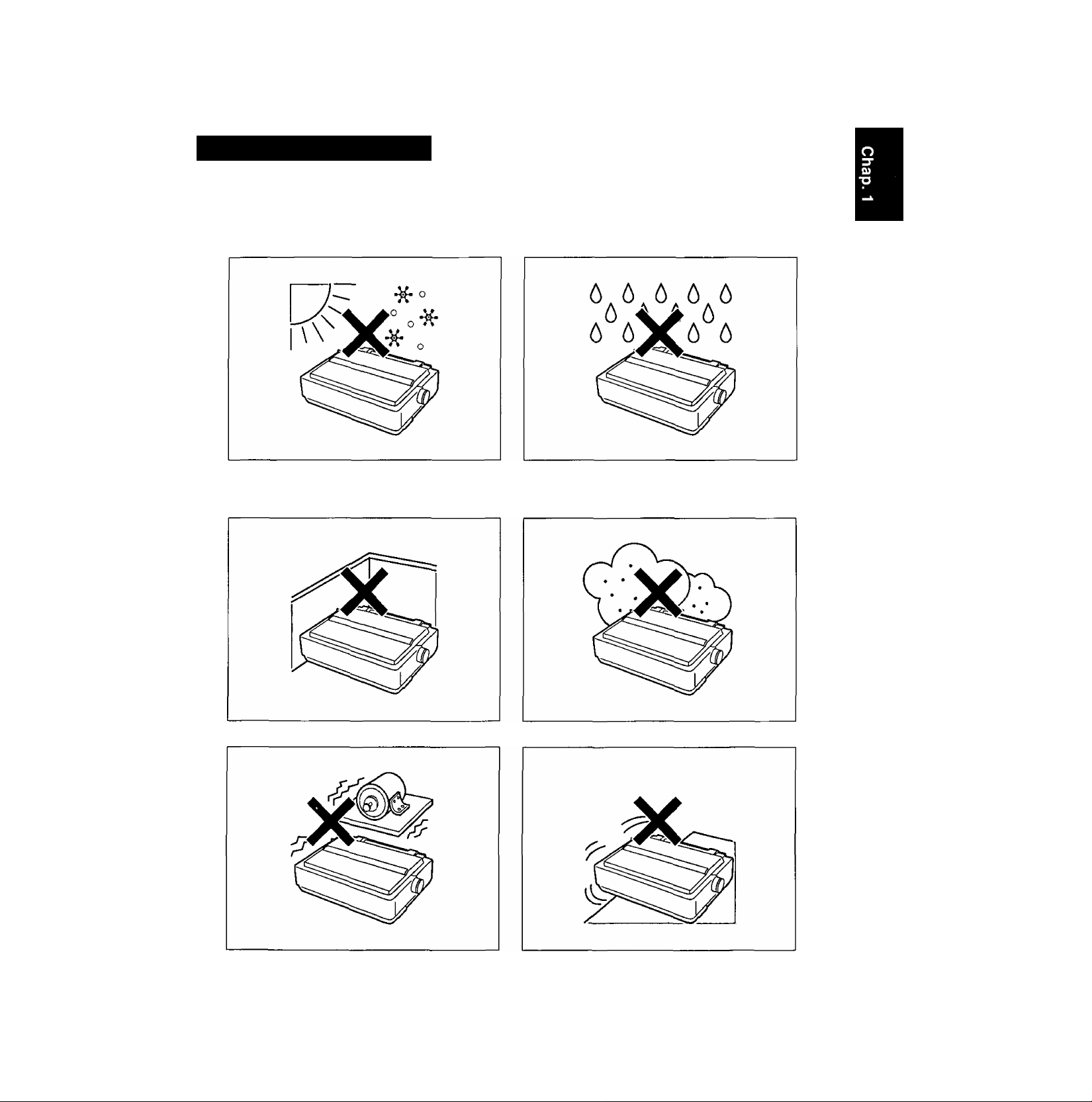
Operating Environment
• Do not use the printer under the following conditions.
Extremely high or low temperature Extremely high or low humidity
[temperature range: 10* to 35*C (50* to 95°F)] (humidity range: 30% to 80% RH)
Areas of poor ventilation
[a minimum of 4" (10 cm) clearance on all
sides is necessary to insure proper ventilation]
Areas of high dust concentration
00
(D
o
<D
<
O
c
CO
to
Areas with extreme vibration
•Power consumption:
(MAX—250 W, Stand by—12 W. Self Test—50 W)
Areas on an unstable or unlevel surface
Page 10
(^EOfflSODS
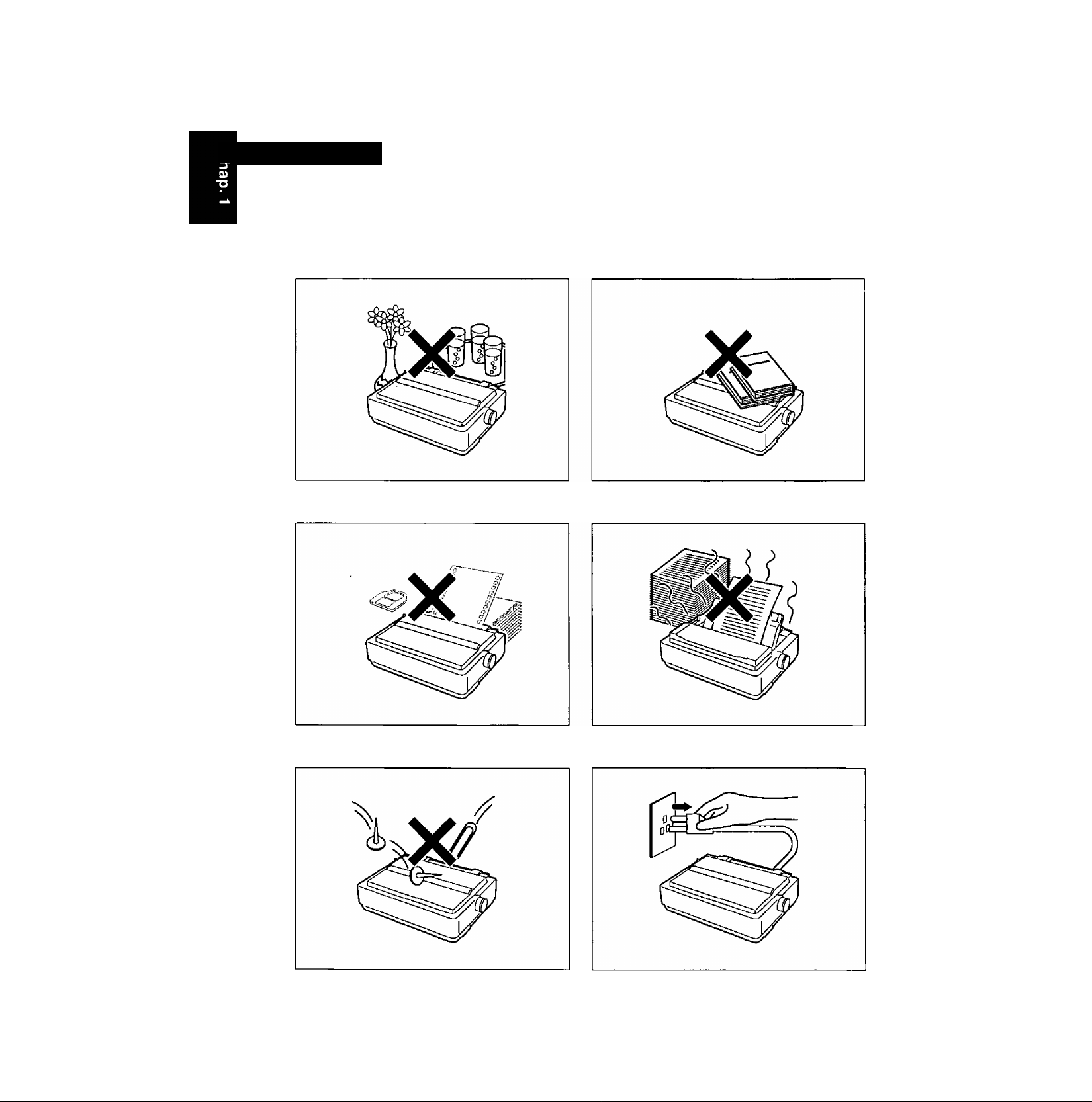
O ■ Precautions
The following precautions are recommended to extend the life of the printer.
w
(D
o
—i
o
<
o
c
CO
0)
a.
Keep all liquids away from the printer.
—Accidental spillage of a liquid into the printer Do not place books, paper, or other items
can cause severe damage. on top of the printer.
Do not operate the printer without paper
and a ribbon cassette installed.
Avoid prolonged use without allowing the
printhead time to cool.
Do not obstruct the movement of the
printhead while in operation.
10
If the printer is not going to be used for an
extended period, unplug the power cord.
Page 11
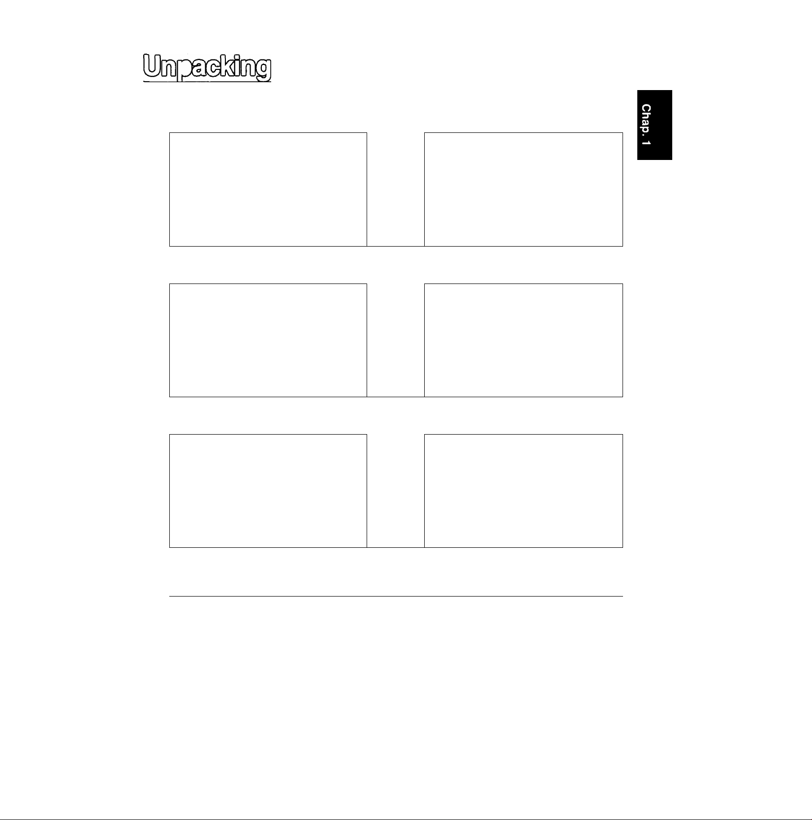
0
Having unpacked the printer, make sure none of the contents shown below are missing or damaged.
Report damage or shortages to the store from which the unit was purchased.
Printer (KX-P3124)
Ribbon cassette (KX-P150)
<D
C?'
CD
(D
O
(D
<
0
m
3.
)
Platen knob
Operating manual
<»
Setup Disk
• The Setup Disk contains a Printer-Driver for Windows Ver. 3.1 (t^ P. 39), a
Function Mode program {o^ P. 70) and a Command Reference program
P. 90).
• To use the Setup Disk you need to have an IBM-PC or a Compatible computer
with a 3.5" floppy disk drive.
• For detailed information on ATM Disk, refer to ATM Disk manual.
ATM Disk
Note:
• It is recommended that you save the original carton and packing materials for proper shipping
and transporting of the printer.
11
Page 12
W
(D
O
(D
-<
O
c
CO
Cl)
a.
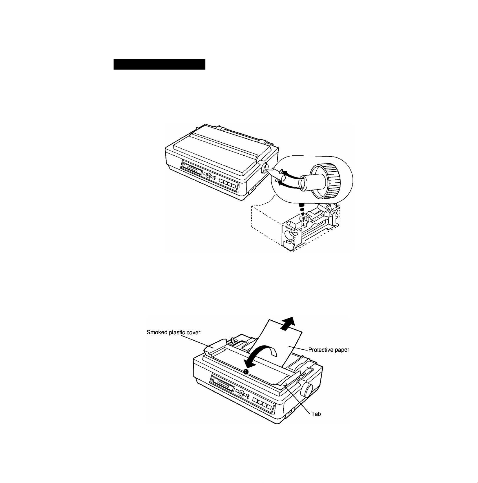
Assembling the parts
Insert the platen knob into the hole on the right side of the printer and
1
rotate it slowly until it slips onto the shaft. Push the platen knob onto the
platen shaft to secure.
Fold the smoked plastic cover, and remove the protective paper.
12
Page 13
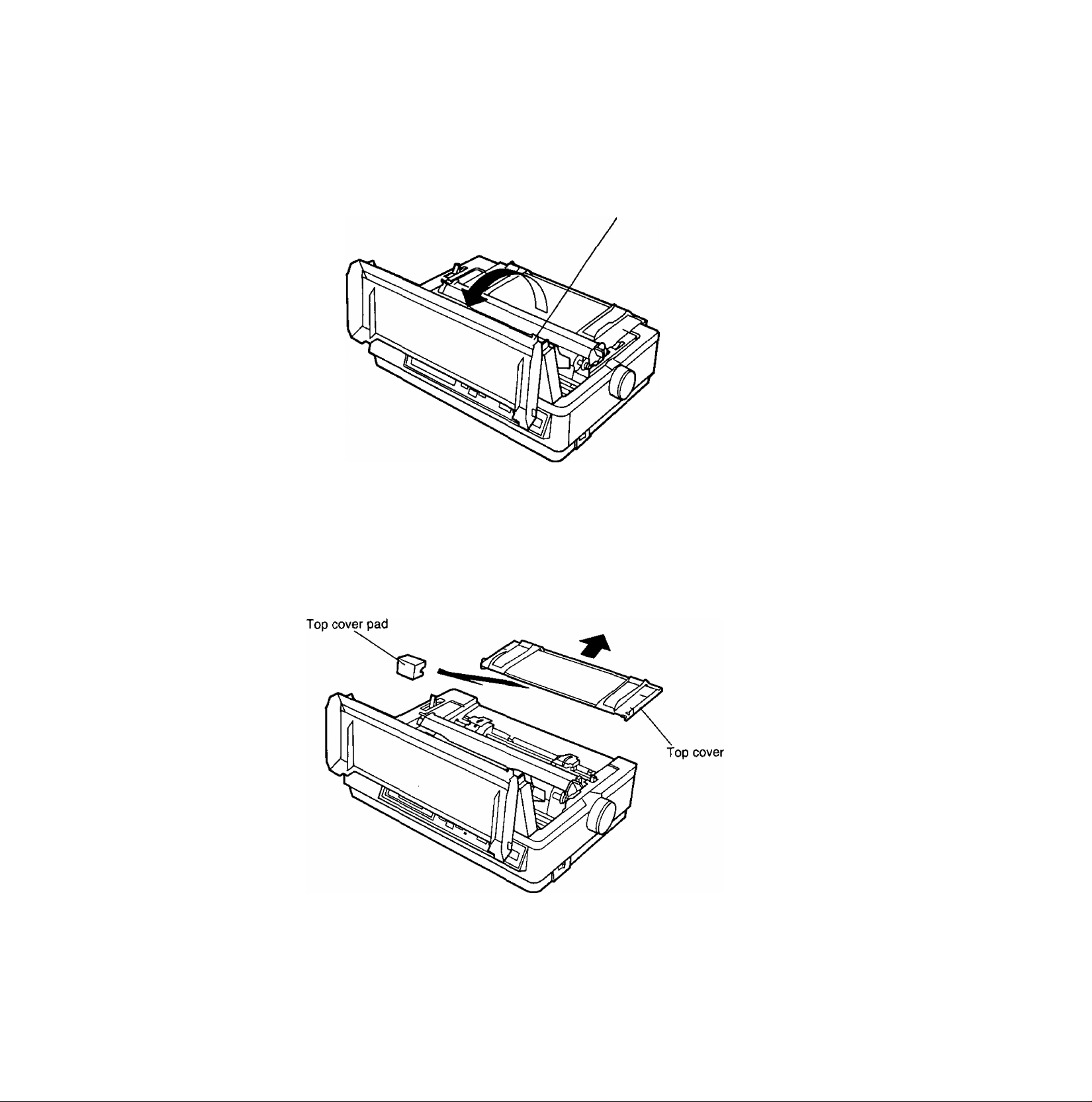
Open the smoked plastic cover.
Jab
CD
<D
O
—t
(D
<
O
c
CO
D1
3.
Remove the top cover pad.
13
Page 14
iMsfesiïtelMnfig?
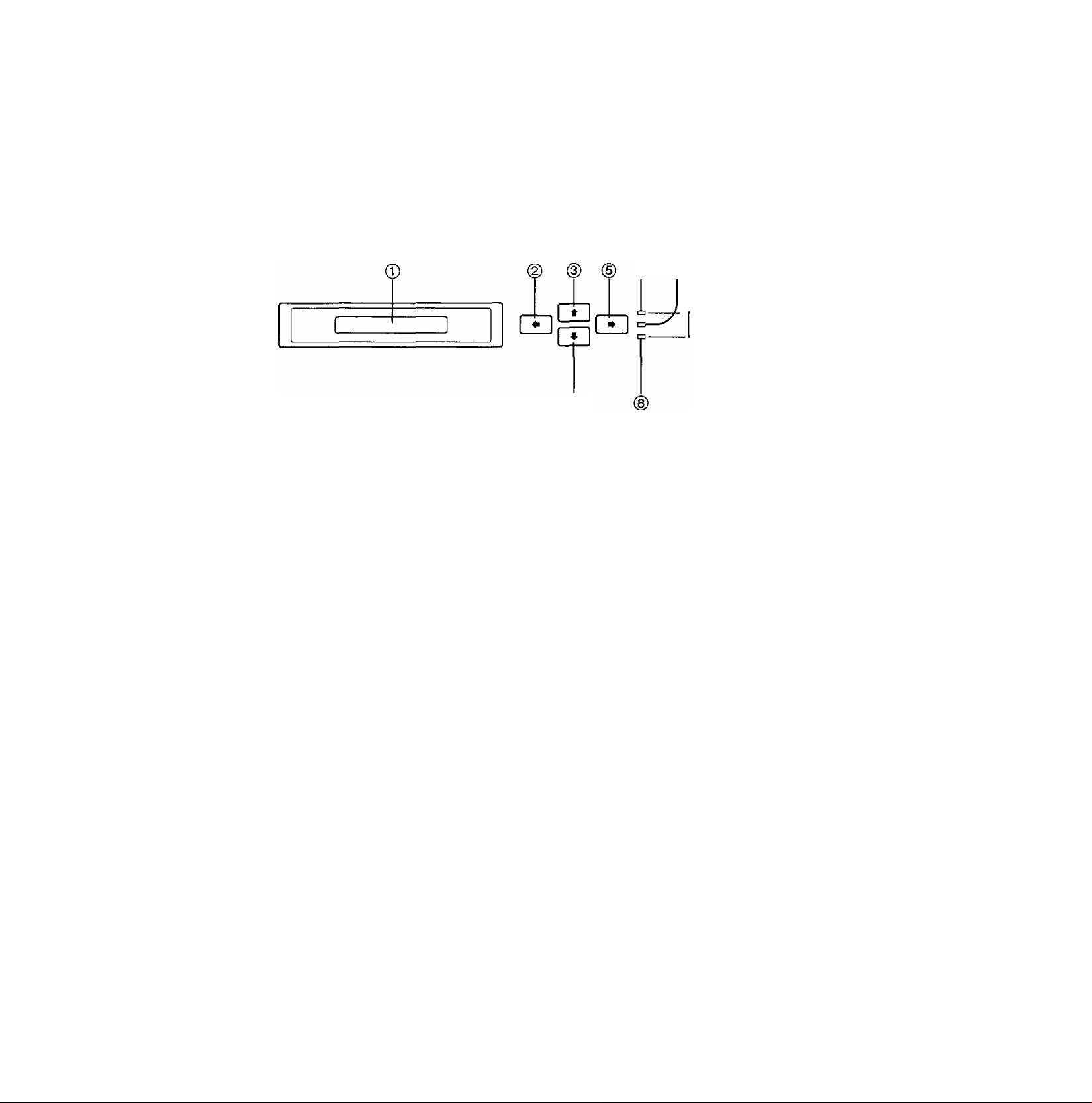
EZ set operator panel
W
O
O
(D
-<
O
c
CO
fi)
3.
© ©
® ® ® ®
16-Character Liquid Crystal Display (LCD)
A 16-character LCD prompts the user with mes
sages and step-by-step instructions.
In case of incorrect operations, the display will
immediately indicate the appropriate error mes
sages so you may take corrective action.
P. 96)
SUPER QUIET (^) Switch
Pressing this switch reduces print noise, however
it also reduces the printing speed. When it is
active, the SUPER QUIET indicator is lit and the
display briefly shows QUIET MODE=ON.
In the Function mode, this switch scrolls back
through the Main menu, the Sub-menu and the
selections or conditions of the item.
TEAR OFF (♦) Switch
Pressing this switch advances or reverses the
paper for tear off in the OFF LINE mode or when
not printing in the ON LINE mode. (Q^ P. 44)
In the Function mode, this switch returns you to
the previous menu level such as “Selection ^
Sub-menu Main menu”.
LOAD/PARK(*) Switch
This switch loads/parks the paper in the OFF
LINE mode or when not printing in the ON LINE
mode.
In the Function mode, this switch lets you scroll
down to the next menu level such as “Main menu
^ Sub-menu ^ Selection”.
TOF SET (^) Switch
This switch allows you to set the Top of Form in
the OFF LINE mode or when not printing in the
ON LINE mode, (t^ P. 50)
In the Function mode, this switch scrolls through
the Main menu, the Sub-menu and the selections
or conditions of the item.
ON LINE/FUNCTION Indicator
This indicator is lit when the printer is in the ON
LINE mode, and the indicator is not lit in the OFF
LINE mode.
In the Function mode, the indicator blinks.
@ SUPER QUIET Indicator (№■ ®)
14
POWER/PAPER OUT Indicator
®
This indicator is lit when the power switch is
turned on and paper is installed. When an out of
paper condition occurs, the POWER/PAPER
OUT indicator blinks.
Page 15
09
(D
O
<D
-<
CO
fl)
ON LINE (FONT) Switch 0
This switch opens and closes the communication
line with the computer. When the power switch is
turned on and paper is installed, the ON LINE
indicator is lit, the display shows “ON LINE", and
the printer is ready to receive data from the com
puter. In the OFF LINE mode, the indicator is out,
the display shows “OFF LINE’’ and the printer can
no longer receive data.
In the Function mode, this switch lets you di
rectly access the FONT selection with one step.
p. 55) @
FF (PITCH) Switch
S)
This switch moves the carriage to the center and
advances the paper to the top of the next page
(depending on your TOF setting) in the OFF LINE
mode or when the printer is not printing in the ON
LINE mode.
In the Function mode, this switch lets you di
rectly access the PITCH Selection with one step.
P. 55)
LF (SET) Switch
This switch advances the paper one line. Holding
the switch down performs multiple line feeds.
These functions are active in the OFF LINE mode
or when the printer is not printing in the ON LINE
mode._________________________________
In the Function mode, this switch sets selec
tions or conditions of the item shown on the dis
play and returns you to the Sub-menu.
FUNCTION Switch
This switch allows you to enter and exit the Func
tion mode.
In the Function mode, the ON LINE/FUNCTION
indicator blinks and the E2 Set Operator Panel
switches have secondary capabilities, for easily
setting your desired print conditions. ((^ P. 52)
15
Page 16
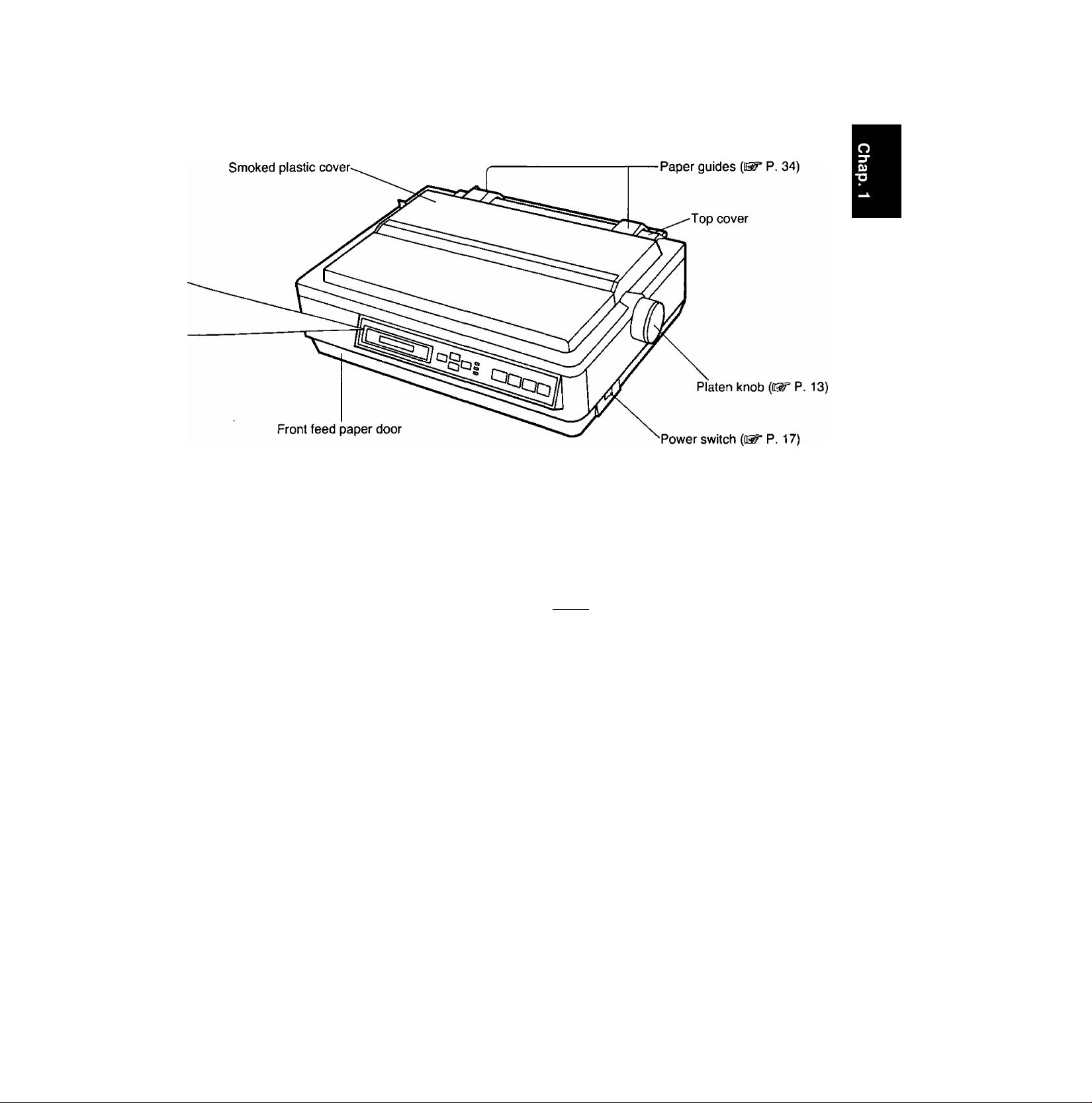
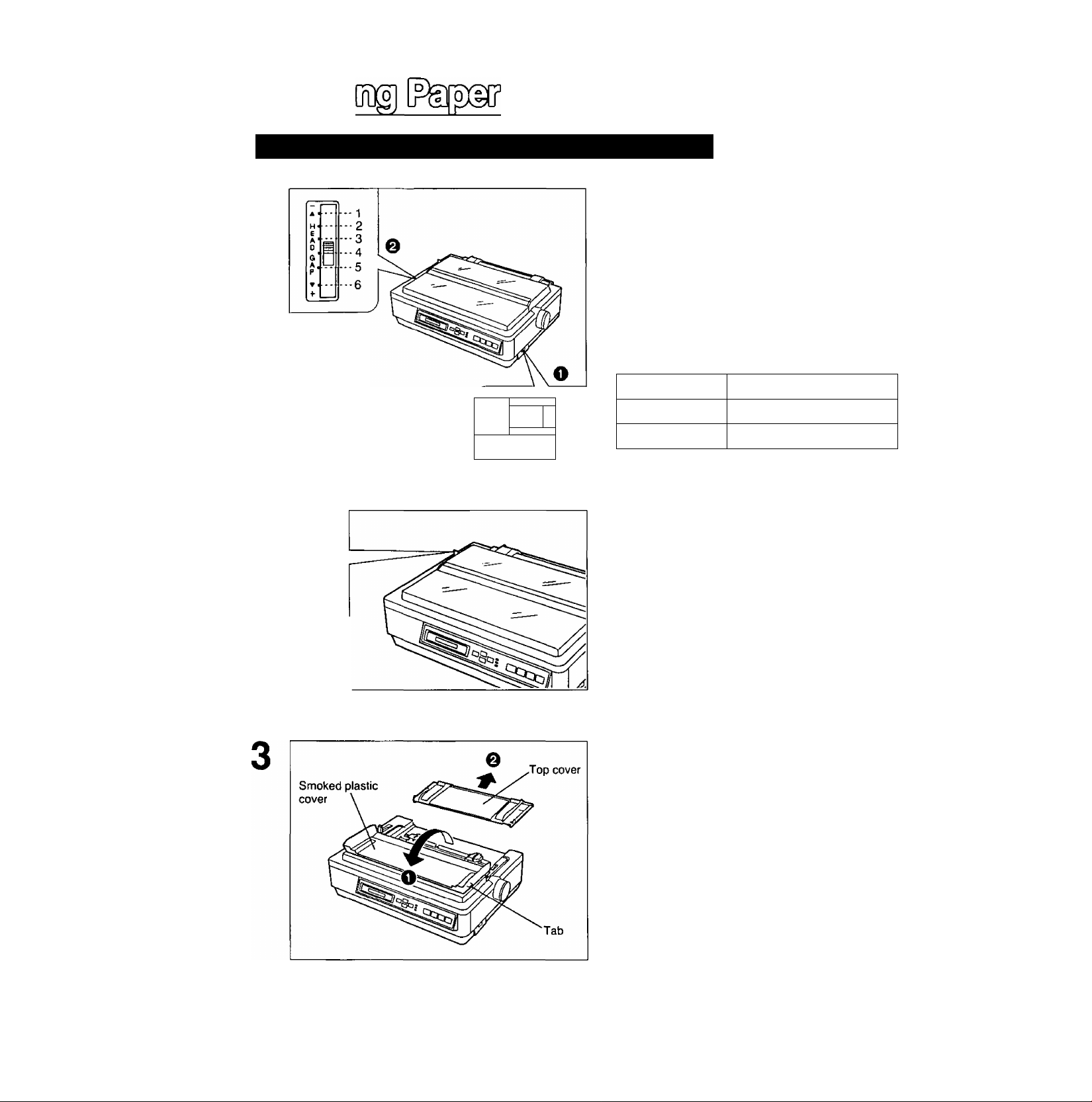
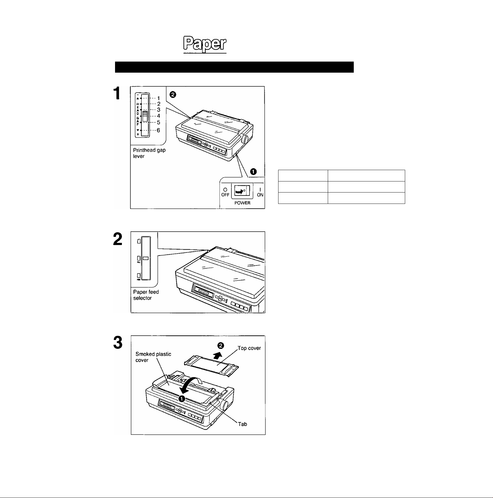
Printhead gap lever
Adjusts the gap between the platen and the printhead. The lever moves
in increments of 0.0028 inch (0.07 mm).
OD
O
o
(D
-<
O
c
0)
fii
3.
Top cover
AC power cord
p. 17)
1—-,
2-—K’
E
X‘
0
4-*-
a’
5--"
p'
6
---
+
Position
1 or 2
3, 4, 5 and 6
Smoked plastic cover
Thinner sheets
Thick or multiple sheets
Used for
Envelopes
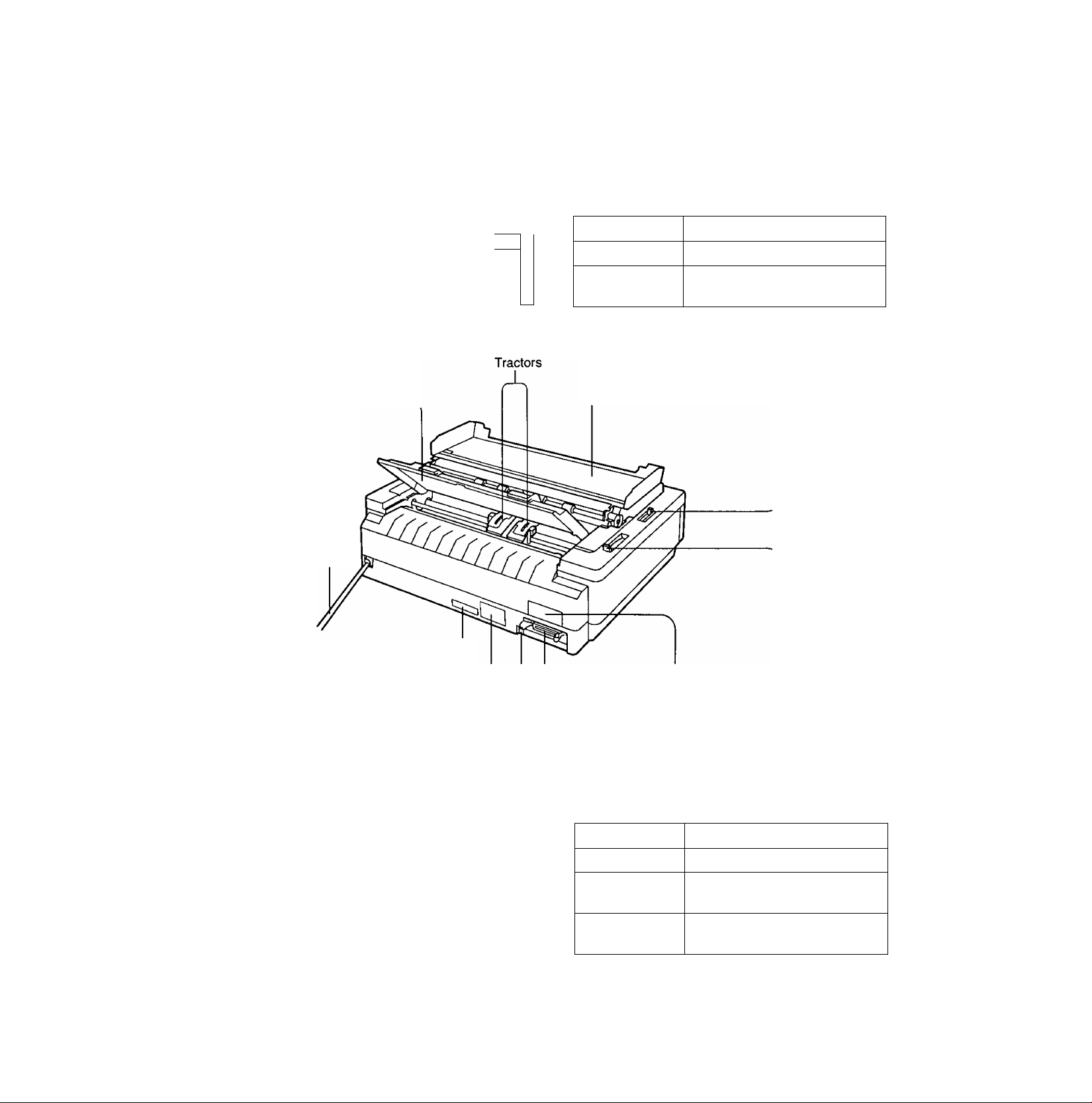
Serial No. label
Nameplate
Frame ground terminal
Centronics parallel interface connector
Paper teed selector (o^ P. 23)
□
Serial interface cover
Position
Q (Friction)
Q (Tractor)
PULL
0 (Tractor)
PUSH
Used for
Single sheets and Envelopes
Fanfold paper with PULL
tractor mode
Fanfold paper with PUSH
tractor mode
16
Page 17
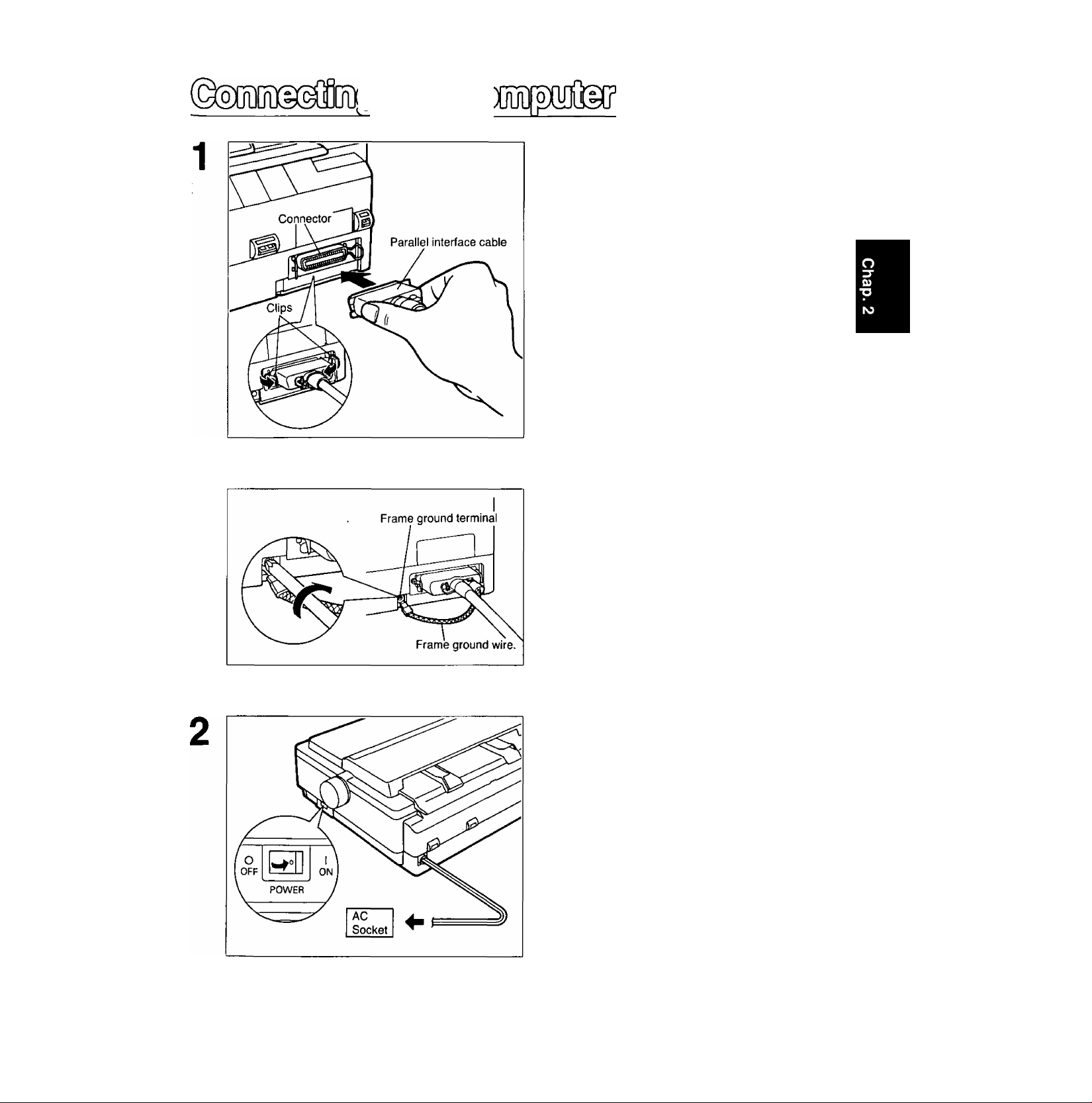
Attach one end of the parallel interface cable to your printer as shown, and the other end to your computer.
Be sure to secure the printer clips.
Note:
• If you do not have a parallel interface cable,
you will need to purchase one from your
local computer store or dealer.
If the cable has a frame ground wire, connect it to the frame ground terminal.
c/>
(D
C
■O
Plug printer into a grounded 3 prong
AC socket.
When power is supplied to the printer, the power
indicator on the EZ Set Operator Panel will light.
17
Page 18
0)
(D
C
■o
oloio
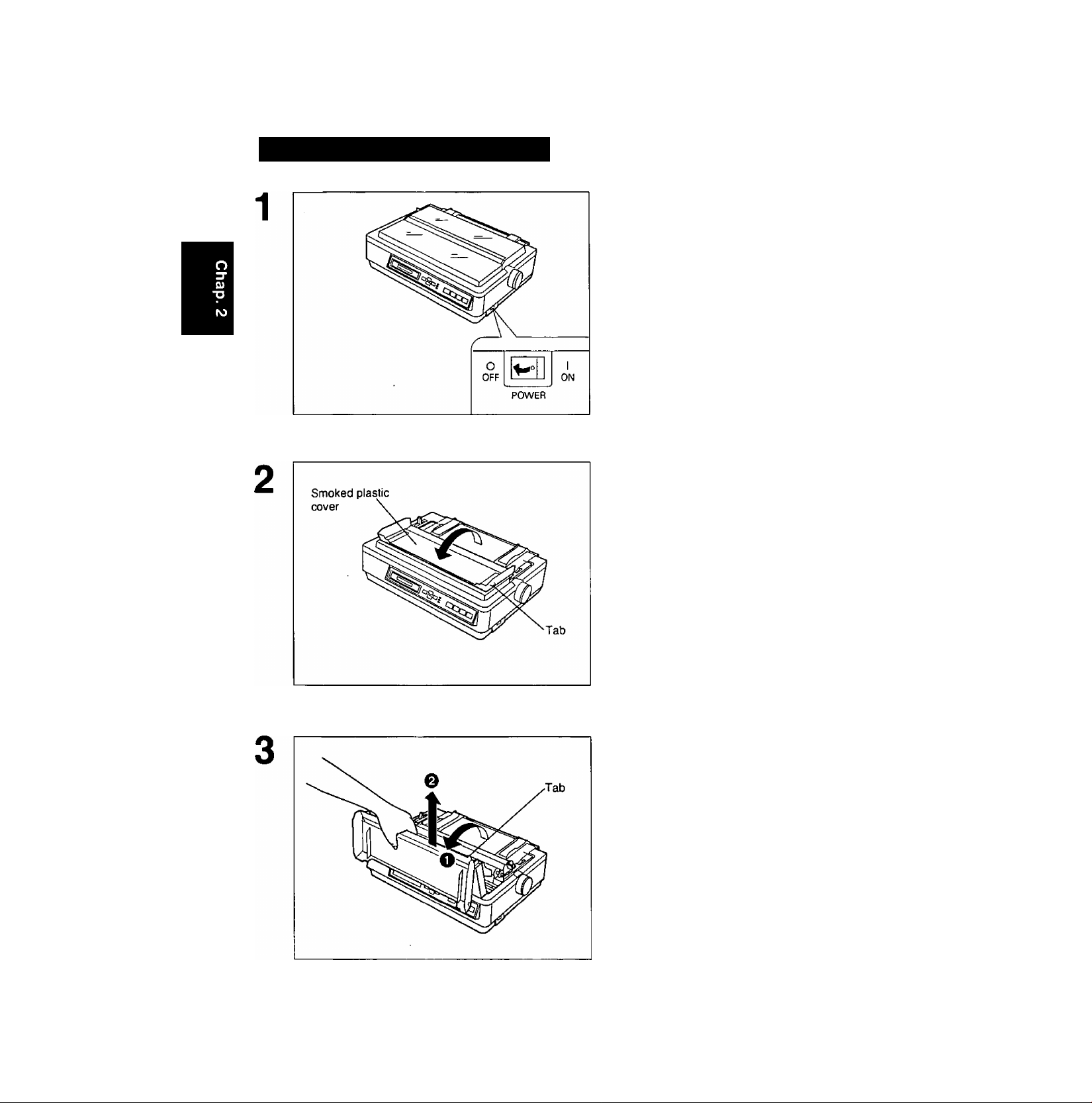
Installing the Ribbon Cassette
Turn the power switch off for safety.
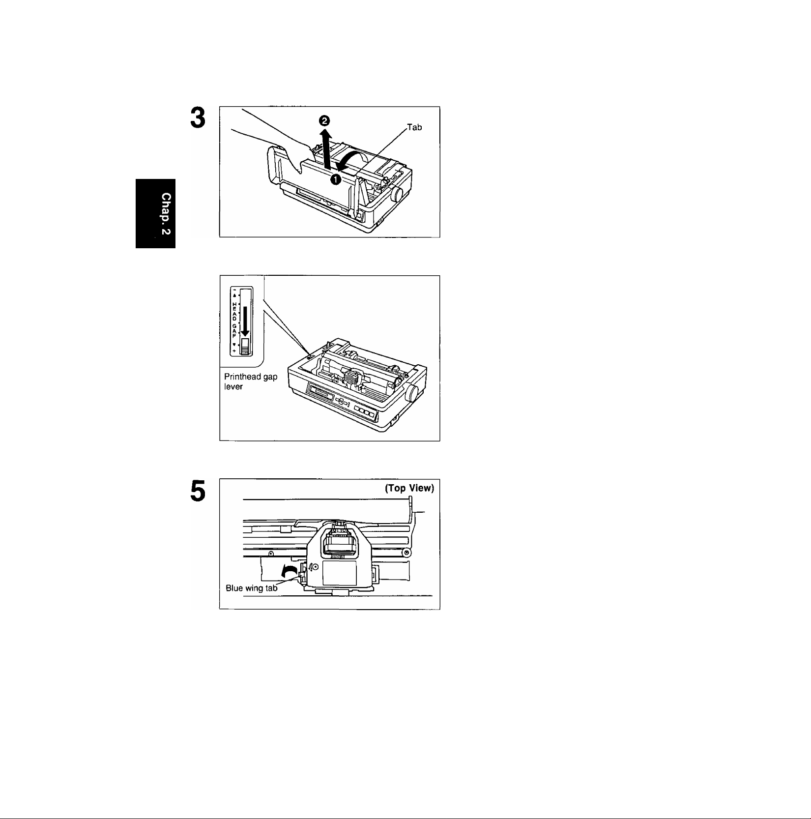
Fold the smoked plastic cover forward
by lifting the tab on right side.
18
O Raise the smoked plastic cover.
0 Remove the smoked plastic cover.
Caution:
•The printhead may be hot, use caution
when cover is open.
Page 19
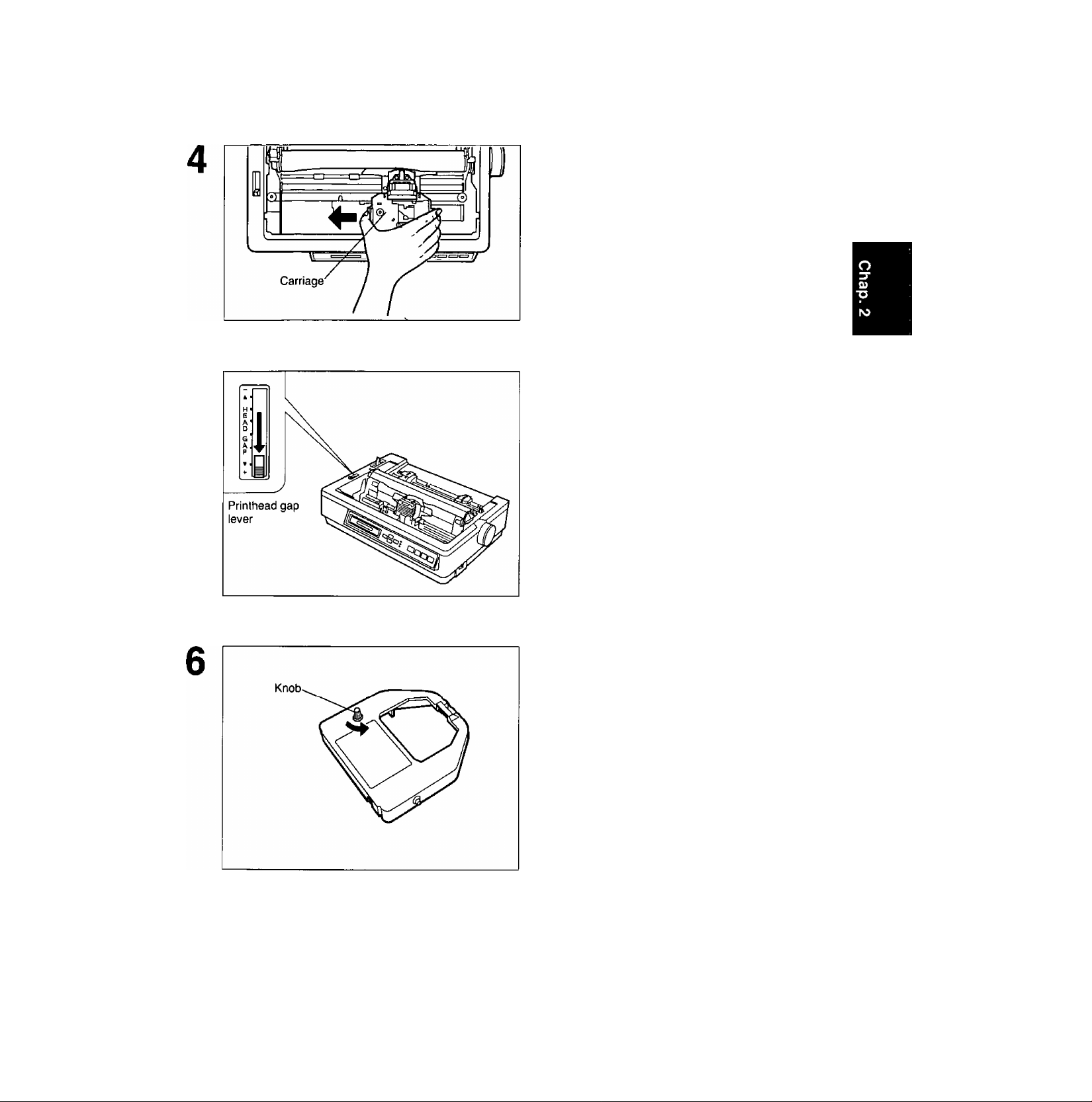
raSofeEOD
Slide the carriage gently toward the
center of the unit.
Move the printhead gap lever to the (+)
position.
CO
(D
C
■O
Rotate the knob on the ribbon cassette
to remove any slack.
19
Page 20
ra0tefe(sin]{^e@3Qa3
(A
(D
C
■O
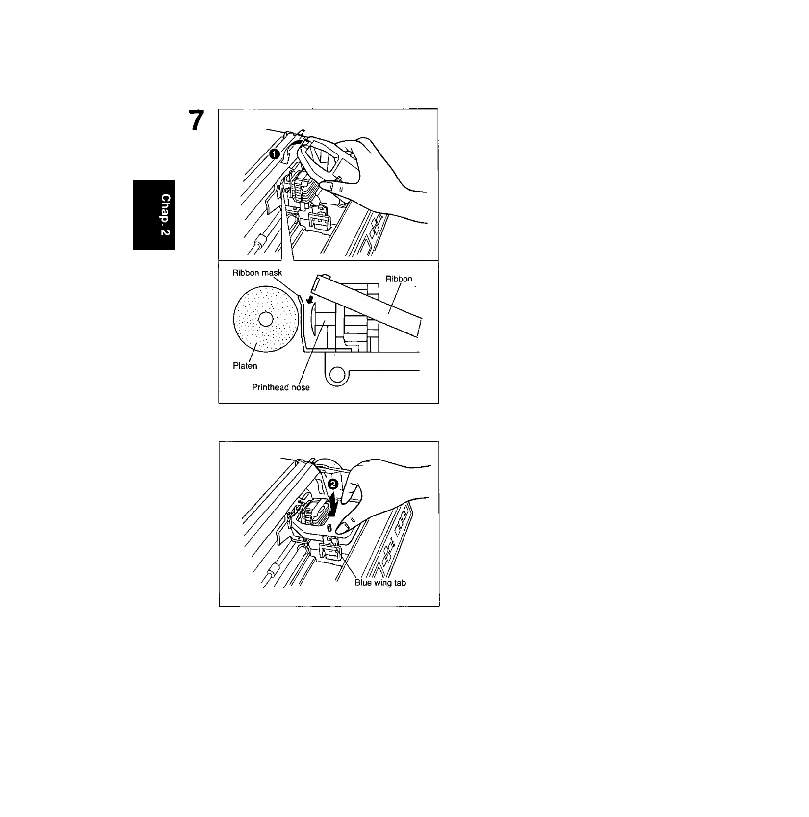
O Slip the ribbon between the ribbon
mask and the printhead nose.
8
Q Press down on rear of the cassette
until the blue wing tab snaps into
place.
Replace the smoked plastic cover.
20
Page 21
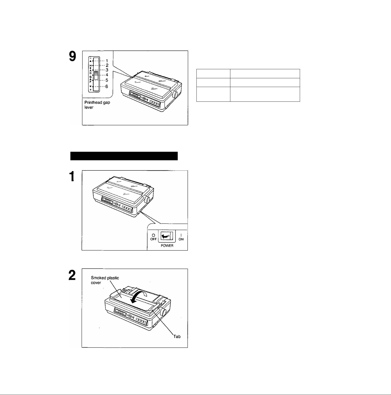
Adjust the printhead gap lever for the
thickness of paper you are using.
Removing the Ribbon Cassette
Position
1 or 2 Thinner sheets
3, 4, 5 and 6
Turn the power switch off for safety.
Thick or multiple sheets or
envelopes
Used for
CO
(D
Fold the smoked plastic cover forward
by lifting the tab on right side.
21
Page 22
CO
<D
C
■O
E3Qofe®0D ^3@@@03s
O Raise the smoked plastic cover.
@ Remove the smoked plastic cover.
Caution:
•The printhead may be hot, use caution
when cover is open.
Move the printhead gap lever to the (+)
position.
Spread the blue wing tab and lift up the
cassette.
22
Page 23
o o.
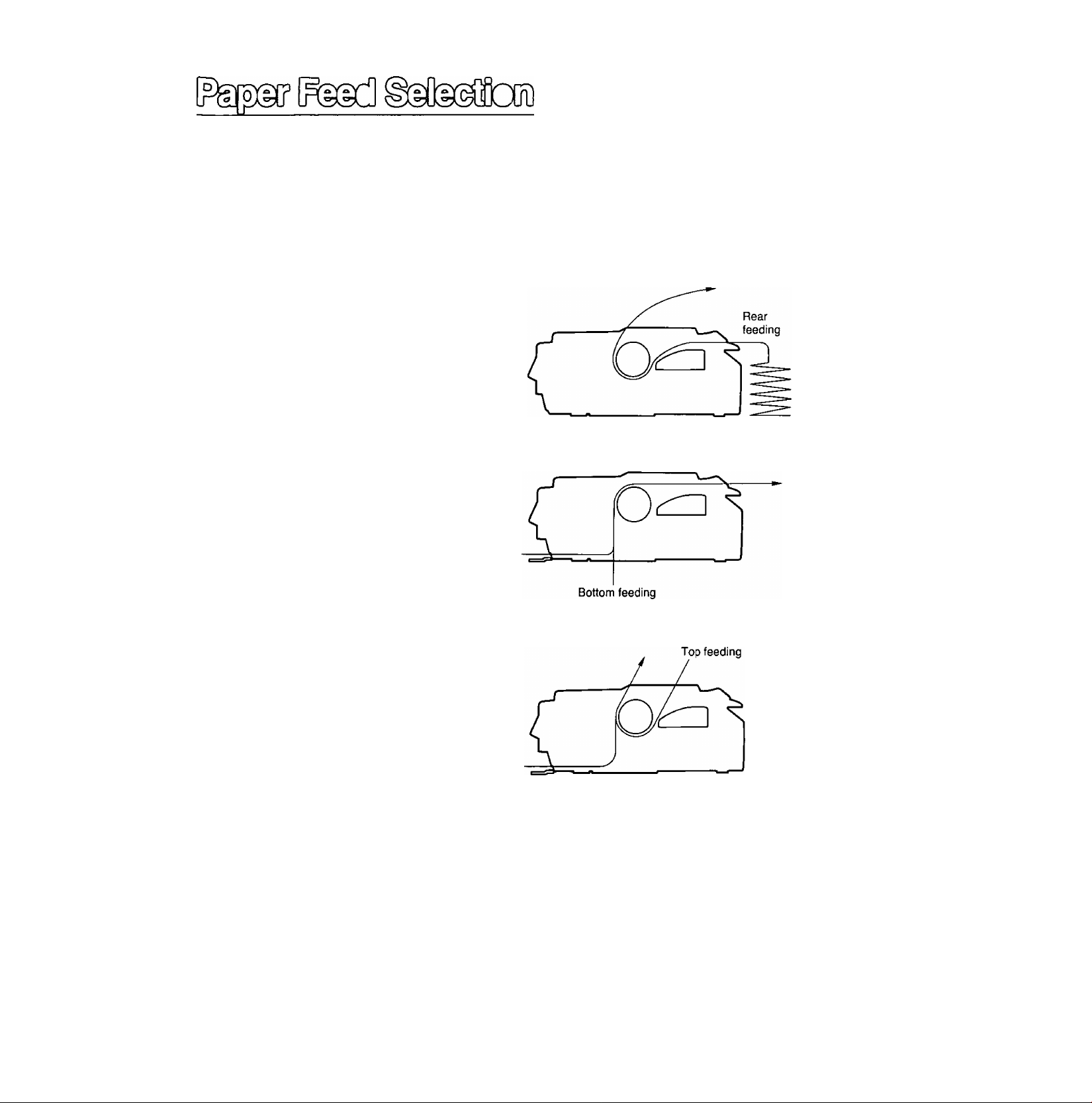
This printer has two paper feed mechanisms to support 4 paper paths. One mechanism is TRACTOR
mode for continuously fed paper. In the tractor mode you can choose between PUSH or PULL.
The other paper feed mechanism is FRICTION mode. In the friction mode you can feed single sheets
or envelopes through the front or top. The optional KX-PT11 Cut Sheet Feeder will accommodate
automatic feeding of single sheets, from the top paper path.
Push Tractor mode (Q PUSH)
—fanfold paper (1 part)
—multipart forms consisting of 2 parts
Pull Tractor mode (0 PULL)
—multipart forms consisting of 3
or 4 parts
—labels
—fanfold paper {1 part)
C/>
o
Front
feeding
Friction mode (Q)
—single sheets
(The KX-PT11 Cut Sheet Feeder
allows you to automatically feed up
to 80 sheets of 20 lb paper.)
—envelopes
Front
feeding
Note:
•For optimum print quality, do not use reverse line feeding in pull mode. If reverse feeding is
necessary in pull mode, set REV LF/PULL in the INSTALL menu to ON through the
Function mode.
•Paper Parking is not available in pull mode.
• Multipart forms consisting of 2 parts, may be used for rear feeding (PUSH mode). For 3 or
4 part forms, we recommend bottom feeding {PULL mode) for optimum print quality.
•When printing on envelopes or thick sheets, front feeding is recommended.
23
Page 24
Fanfold Paper; Push Tractor Mode—Rear Feed
O Turn the power on.
1
A beep will sound once and the PAPER OUT
indicator will flash. This indicates that there is
no paper installed in the printer.
CO
<D
C
■o
Printhead gap
lever
1
Paper feed
selector
0
OFF
POWER
ON
0 Adjust the printhead gap lever for
the thickness of paper you are
using.
Position Used for
1 or 2 Thinner sheets
3, 4, 5 and 6
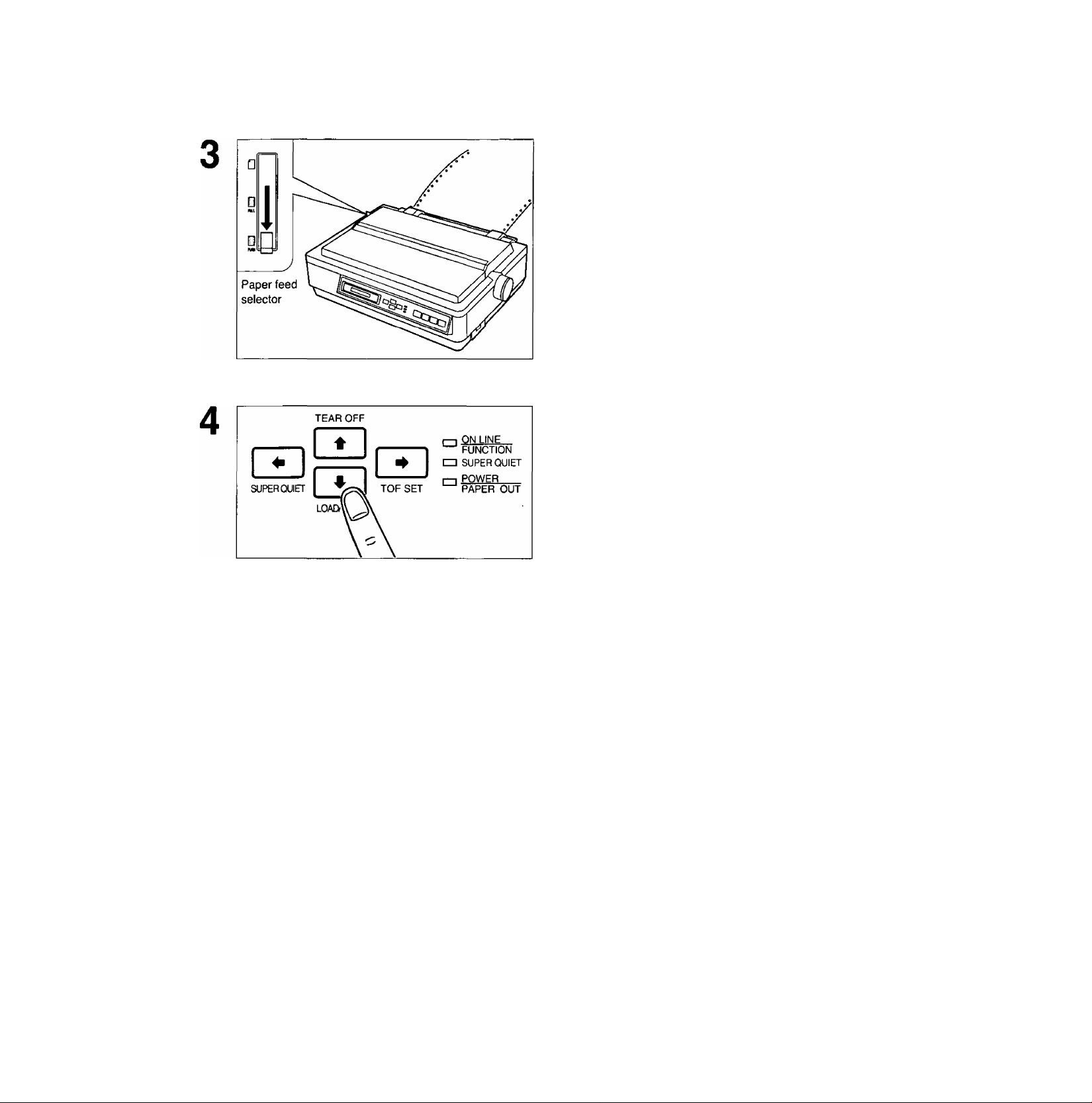
Set the paper feed selector to the “0 PUSH” position.
The display briefly shows “TRACTOR/PUSH".
Thick or multiple sheets
24
O Fold the smoked plastic cover for
ward by lifting tab on right side.
0 Remove the top cover.
Page 25
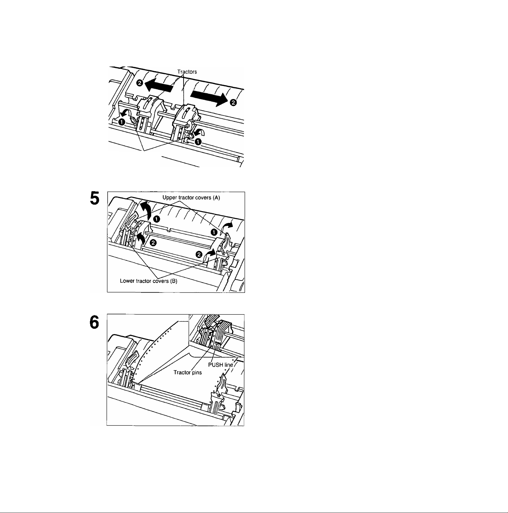
Tractor clamping
levers
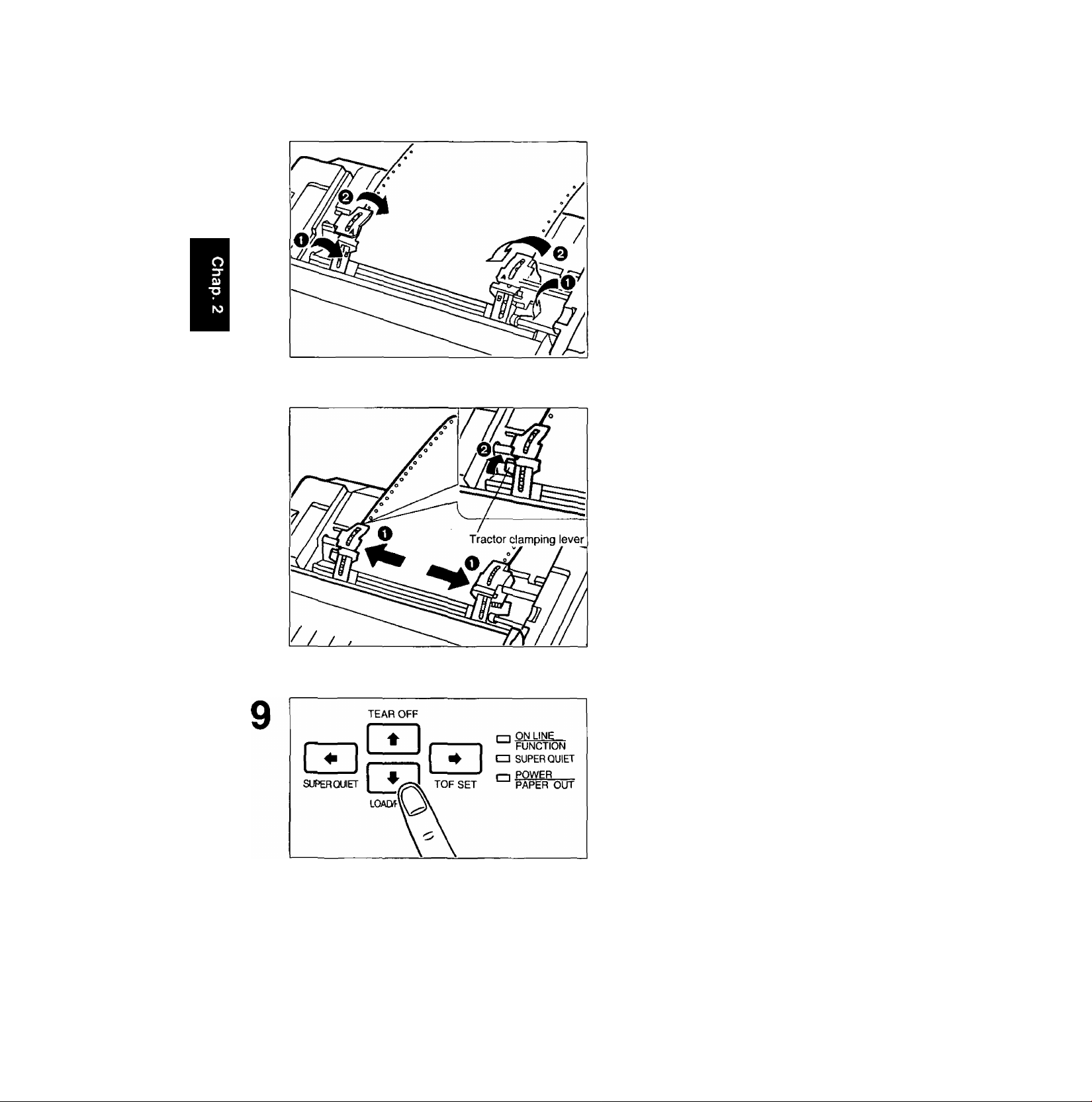
ODQSíMIBiDg)
O Unlock the tractors by pulling the
tractor clamping levers forward.
0 Slide the tractors to accommodate
the approximate width of the paper
being used.
In most applications, you will find that the 0
indicator on the tear bar is a useful tool for
predetermining your left most print position.
O Raise the upper tractor covers (A).
0 Raise the lower tractor covers (B).
*o
CO
<D
C
Place paper holes onto tractor pins and
align top edge of paper with PUSH lines
on tractors.
25
Page 26
CO
(D
C
■O
QsSMilg) [?fe(P(7
8
O Close the lower tractor covers (B).
0 Close the upper tractor covers (A).
O Adjust the tractors to remove any
slack in the paper.
0 Lock the tractor clamping levers.
26
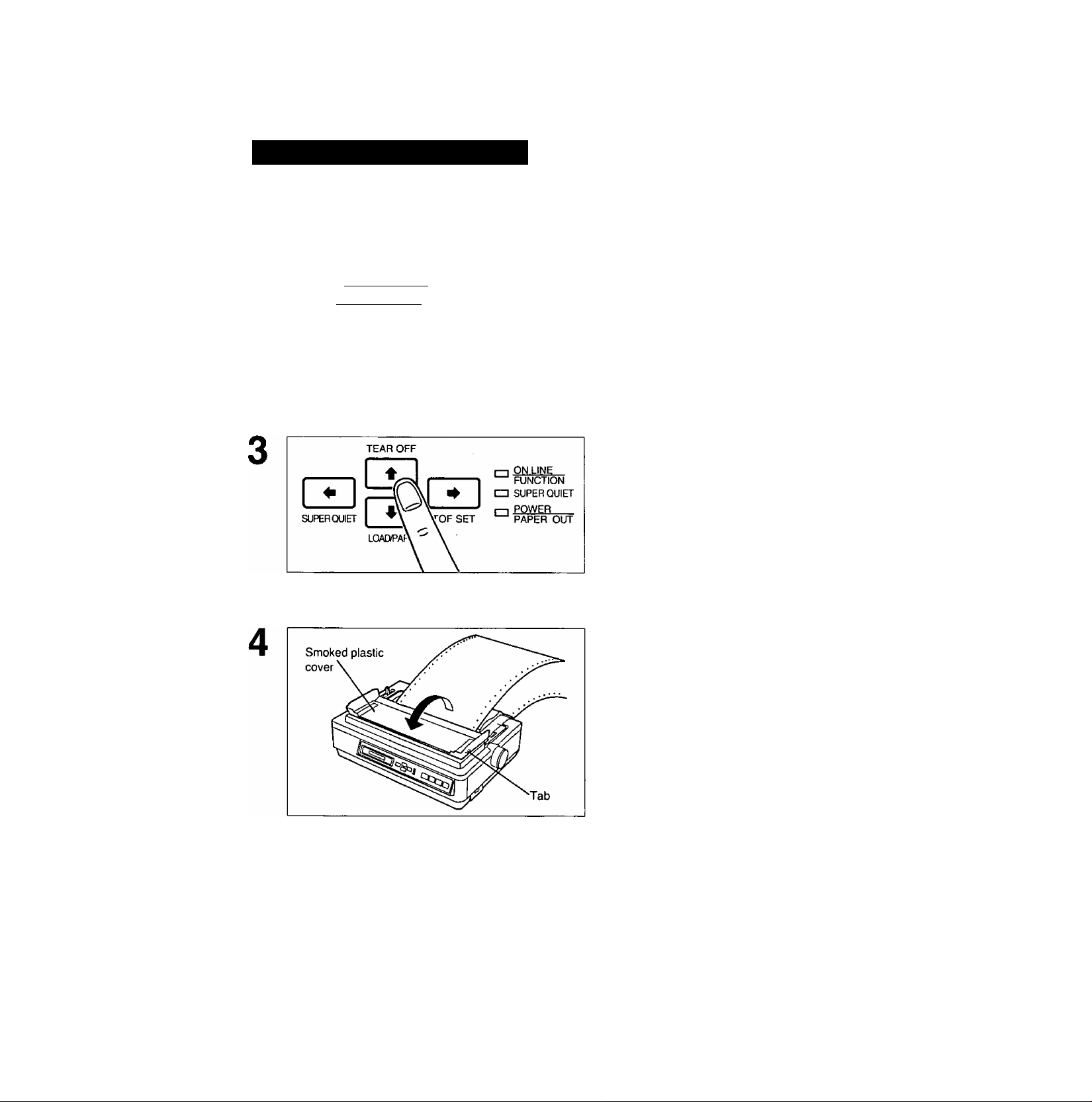
Press [T) (LOAD/PARK).
This will load the paper to the first print line.
The display shows “PAPER LOAD” and the
PAPER OUT indicator will stop blinking.
Page 27
10
11
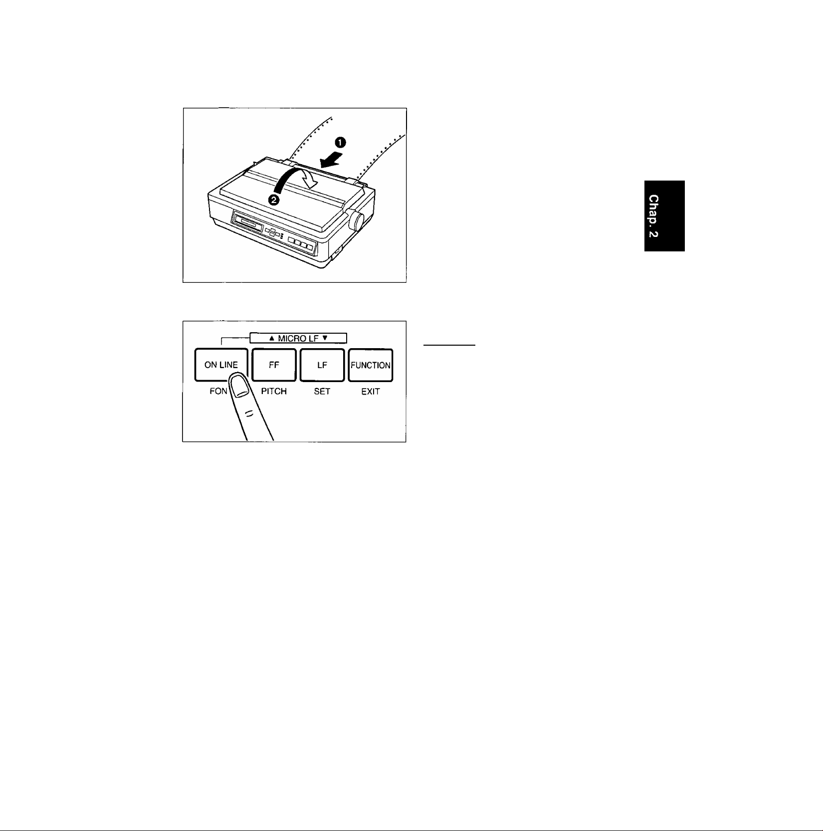
O Replace the top cover.
0 Close the smoked plastic cover.
If ON LINE indicator is not lit, press
[ON LINE] to get ready to print.
CO
(D
Note:
•To avoid paper cur! in PUSH mode, park
the paper after use.
27
Page 28
CO
o
c
■O
[ñlgíMlflnii^
Fanfold Paper: Pull Tractor Mode—Bottom/Front Feed
O Turn the power on.
A beep will sound once and the PAPER OUT indi
cator will flash. This indicates that there is no paper
installed in the printer.
Q Adjust the printhead gap lever for
the thickness of paper you are
using.
Position
1 or 2 Thinner sheets
Used for
3, 4, 5 and 6
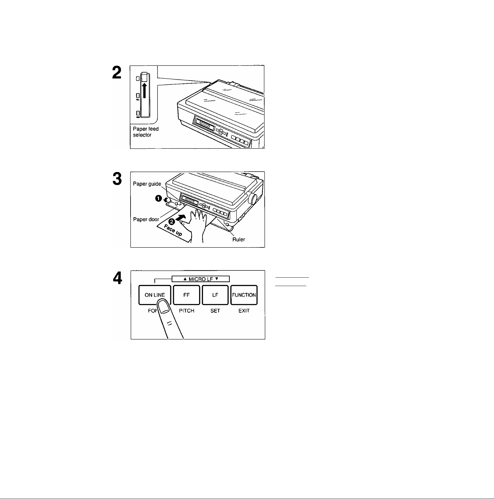
Set the paper feed selector to the
“0 PULL” position.
The display briefly shows “TRACTOR/PULL”.
Thick or multiple sheets
O Fold the smoked plastic cover for
ward by lifting tab on right side.
0 Remove the top cover.
28
Page 29
Tractor clamping
levers
IMMBDïig)
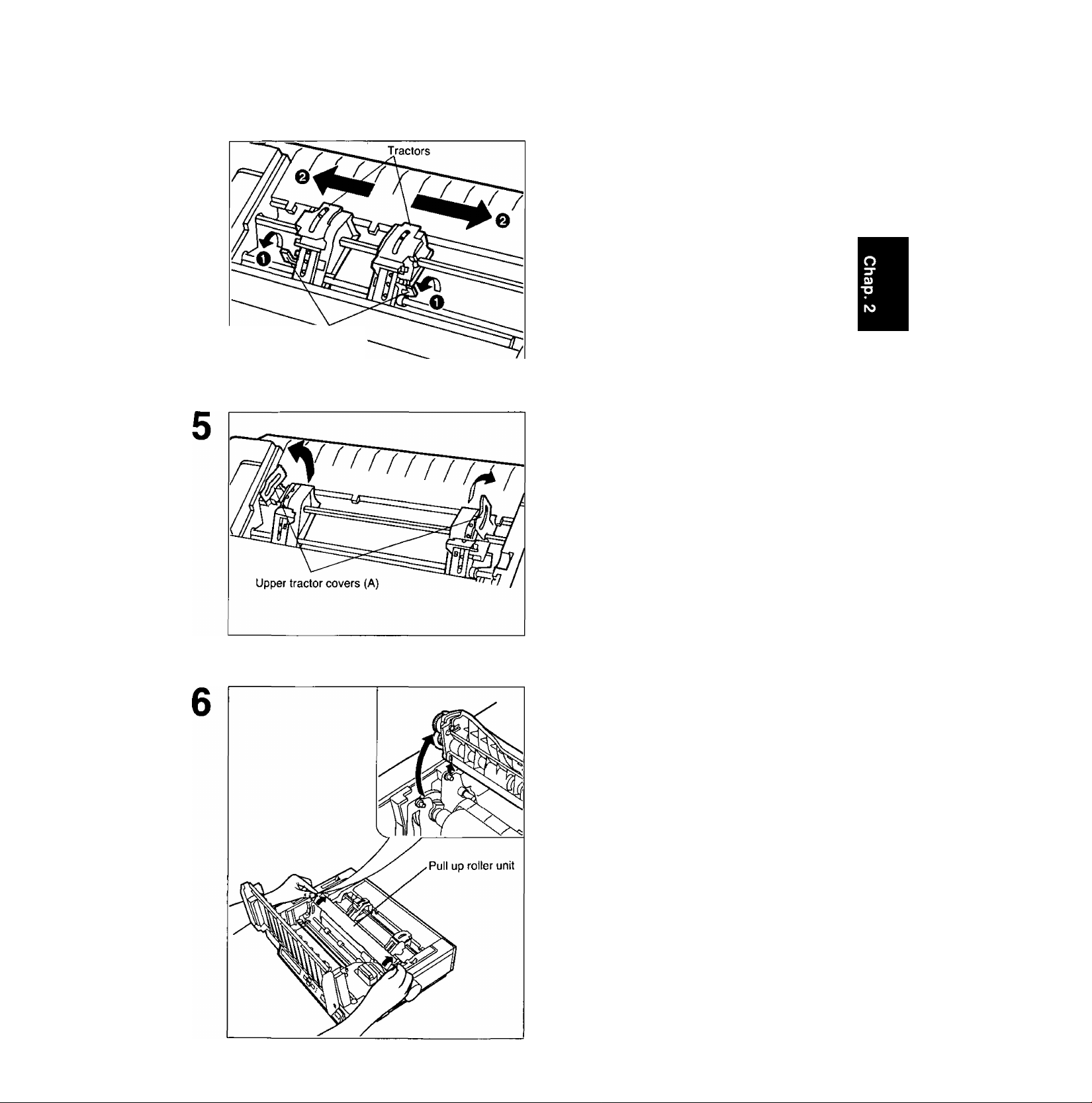
O Unlock the tractors by pulling the
tractor clamping levers forward.
0 Slide the tractors to accommodate
the approximate width of the paper
being used.
In most applications, you will find that the 0
indicator on the tear bar is a useful tool for
predetermining your left most print position.
Raise the upper tractor covers (A) only.
CO
(D
C
*o
Remove the pull up roller unit as shown.
Note:
• Do not forget to remove the pull up roller
unit before using PULL mode.
29
Page 30
C/)
(D
c
*o
ODDSiMBji©
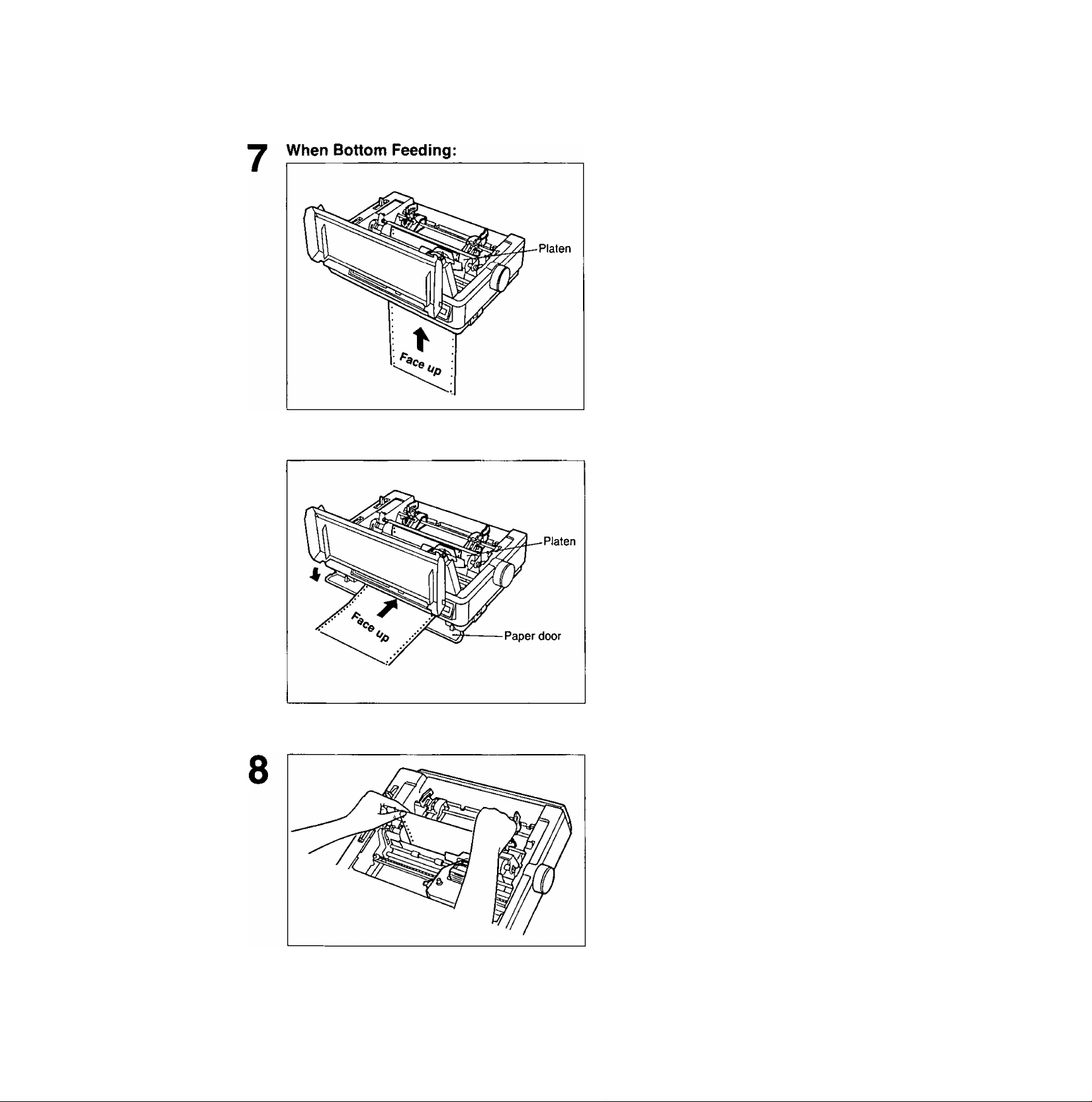
Push the paper up through the bottom
opening until it appears in front of the
platen.
When Front Feeding:
Open the paper door and insert the
paper along the paper guides until it
appears in front of the platen.
Note:
•When feeding fanfold paper through the
front paper door, paper types and condition,
as well as temperature and humidity
conditions may effect accurate line feeding
and print quality may not be optimum. For
optimum output bottom feed is
recommended.
Adjust the paper position by pulling it
up as shown.
30
Page 31

10
QseiMDDDiig
O Align the paper sprocket holes
with the tractor pins making sure
the paper is straight.
Q Close the tractor covers.
O Adjust the tractors to remove any
slack in the paper.
0 Lock the tractor clamping levers.
c/>
(D
c
■O
11
Replace the pull up roller unit.
Note:
•Be sure to press down the pull up roller unit
until it snaps into place.
31
Page 32

CO
(D
C
T3
OMMBjDg] ffepa?
12
13
O Replace the top cover to its origi
nal position.
0 Close the smoked plastic cover.
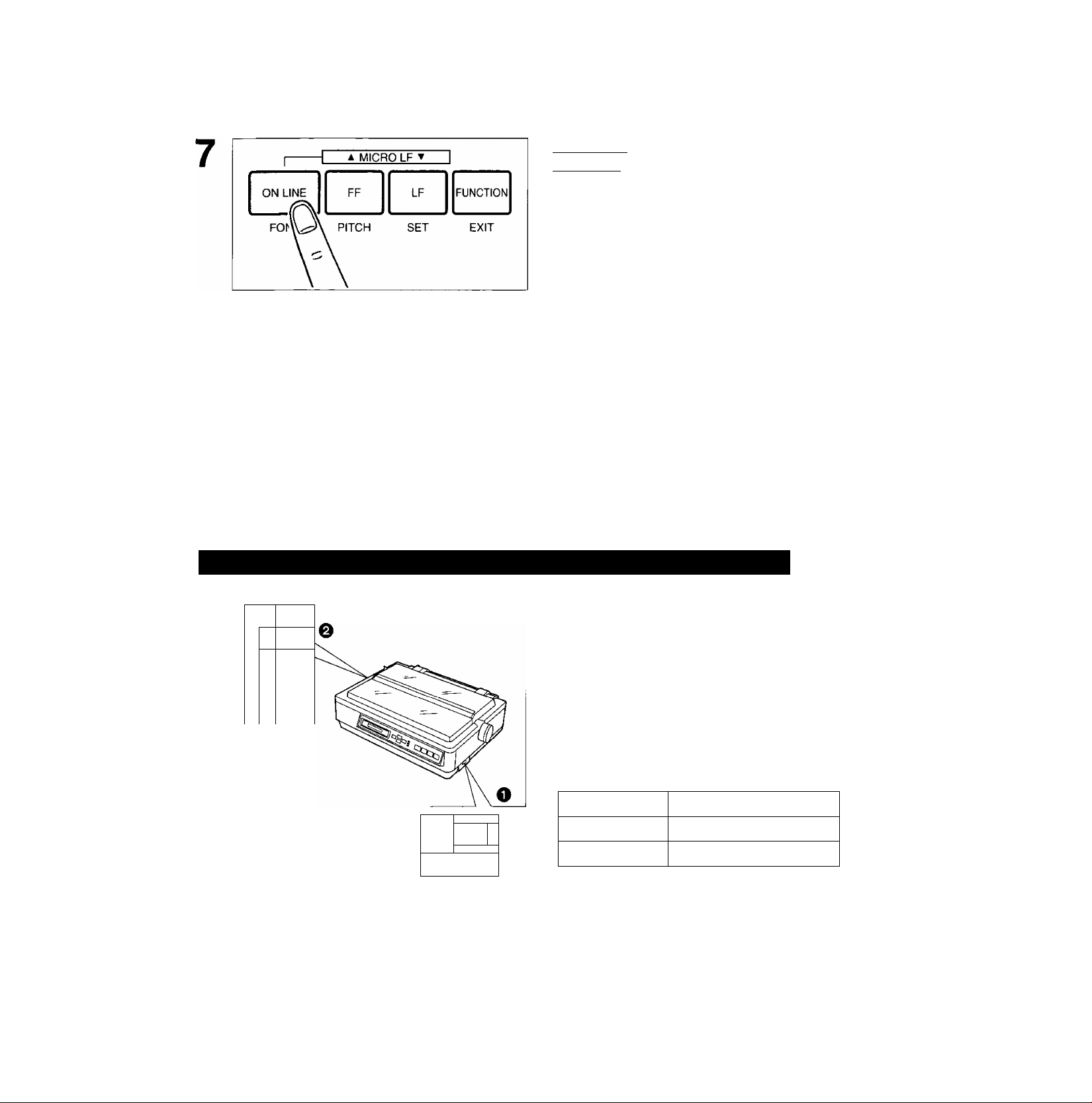
If ON LINE indicator is not lit, press [ON LINE) to get ready to print.
Note:
• In the pul! tractor mode, reverse feed functions will not feed paper correctly and the resulting
printout may not be correct.
If reverse feeding is necessary in pull mode, set REV LF/PULL in the INSTALL menu to ON
through the Function mode.
32
Page 33

ODOgteOBjilg
Single Sheets and Envelopes: Friction Mode—Top Feed
O Turn the power switch on.
A beep will sound and the PAPER OUT indica
tor will flash. This indicates that there is no
paper installed in the printer.
Q Adjust the printhead gap lever for
the thickness of paper you are
using.
CO
o
Position
1 or 2
3, 4, 5 and 6 Thick sheets or Envelopes
Set the paper feed selector to the
position.
The display briefly shows “FRICTION".
Thinner sheets
Used for
O Fold the smoked plastic cover by
lifting tab on right side.
Q Reposition the top cover into the
singie sheet position by inserting
the top cover pins into the siots in
the printer.
33
Page 34

CO
(D
C
■O
QjQ@[№l|]
Separate the paper guides to the ap
proximate width of your paper.
Note:
•To predetermine your left most print
position, move the left paper guide until it
clicks into place.
Insert one sheet of paper into the paper
guide slots.
The paper will automatically load to the first print
line.
34
Fold the smoked plastic cover until it
rests against top cover.
Page 35
If ON LINE indicator is not lit, press
(ON LINE) to get ready to print.
Note:
•If the paper does not automatically load, press (5D (LOAD/PARK).
•When the paper feed selector is in the “0” position, the buzzer will sound to inform you that
the selector is in the wrong position.
•When loading an envelope, if the envelope will not load smoothly, move the paper feed
selector to the “0 PULL” position and insert the envelope manually, then move the selector
back to the “Q” position.
•When printing on envelopes or thick sheets, front feeding is recommended.
Single Sheets and Envelopes: Friction Mode—Front Feed
O Turn the power switch on.
1
Printhead gap
lever
A Ц
H<
E
A '
0
a'
▼ 1
+
... 1
--2
...
g
...4
--5
A beep will sound and the PAPER OUT indica
tor will flash. This indicates that there is no
paper installed in the printer.
...0
0 Adjust the printhead gap lever for
the thickness of paper you are
using.
0)
(D
C
■O
0
OFF
^0
POWER
ON
Position Used for
1 or 2 Thinner sheets
3, 4, 5 and 6
Thick sheets or Envelopes
35
Page 36
CO
<0
c
■O
Set the paper feed selector to the
position.
The display briefly shows "FRICTION".
O Open the paper door.
0 Insert one sheet of paper along the
front paper guide until you feel re
sistance.
The paper will automatically load to the first
print line.
If ON LINE indicator is not lit, press
(ON LINE) to get ready to print.
Note:
• If the paper does not automatically load, press (5D (LOAD/PARK).
•When the paper feed selector is in the "0” position, the buzzer will sound to inform you that
the selector is in the wrong position.
•When loading an envelope, if the envelope will not load smoothly, move the paper feed
selector to the “0 PULL” position and insert the envelope manually, then move the selector
back to the “Q" position.
•When printing on envelopes or thick sheets, front feeding is recommended.
36
Page 37
OCiD@[aiB¡Dg
Characters Alignment
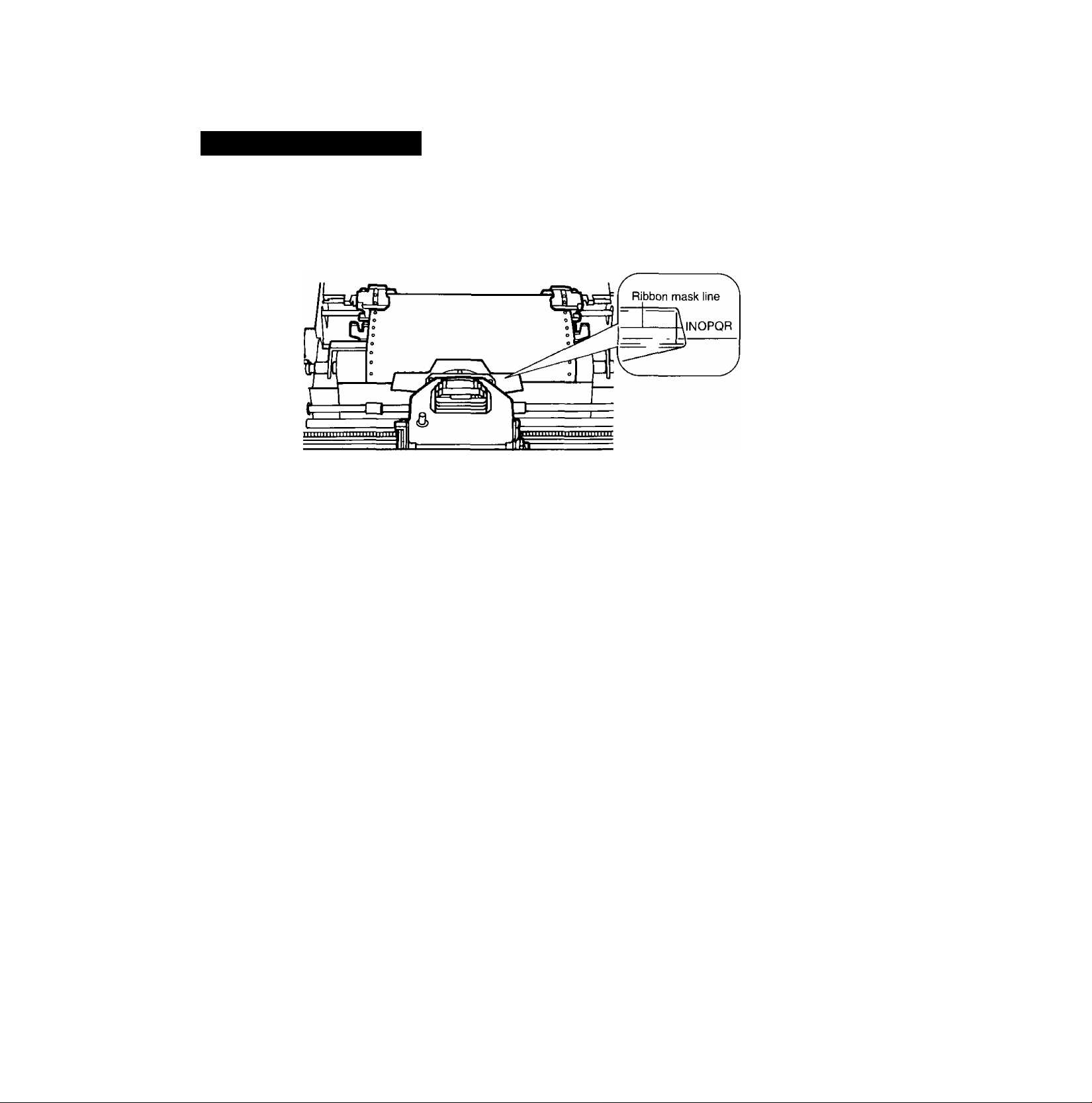
The center of all characters printed on this printer will be aligned with the ribbon mask line (RML).
The RML is a useful marker that shows you exactly where your print line is located.
CO
o
Note;
• Remember that once you rotate the platen knob, the top of form (TOP) will no longer be
recognized.
37
Page 38

The Printer-Driver Selection contains the software codes your application software program uses to
access the printer's features,
This procedure is the final step before printing and is performed in your application software program.
The steps will vary, depending on the software program. Consult your software package for proper
procedures. The Panasonic KX-P3124 will be your first choice. However, if the Panasonic KX-P3124
printer is not listed in your software, you must select an alternative from the following table.
Printer-Driver Selections (in order of priority)
Color Printer Selections'^
Printer Selection
(KX-PCK11 Color Kit must be installed
in the KX-P3124)
CO
0
C
■O
Panasonic KX-P3124
Panasonic KX-P3123 Panasonic KX-P3123
Epson LQ-570 (ESC/P2™) Panasonic KX-P2124
Panasonic KX-P2124 Panasonic KX-P2123
Panasonic KX-P2123 Epson LQ-860
Panasonic KX-P1124/
Epson LQ Series
IBM Proprinter X24E
IBM Proprinter X24
When you use IBM Proprinter X24E/X24 mode;
Change the Emulation to IBM Proprinter X24E/X24 mode in the Function mode (0^ P. 52—77) and
select the appropriate Printer-Driver in the software package.
* To obtain color and utilize the internal scalable fonts, the Panasonic KX-P3124 printer driver must
be selected in your software.
Panasonic KX-P3124
Epson LQ-2500/2550
*
38
Page 39

DoiiigiMIDCiJi]^ Q PM(sx!i!^ SdDd
If you are using Windows Ver. 3.1, please insert your Setup Disk into drive A or B and follow the
directions below.
Before you use the Setup Disk, it is recommended that you make a back-up copy and store the
original in a safe place.
Note:
• Use the DISKCOPY command of the operating system to make a back-up copy. Refer to your
DOS manual for further information.
In “Main Group”, select “Print
1
Manager”.
in “Options”, select “Printer
Setup”.
Click Add>>
In “List of Printers”, seiect
“Install Unlisted or Updated
Printer”.
Click Install...
Insert the Setup Disk into
drive A.
If you choose to insert the Setup Disk
into drive B, you must type B:\.
Default Printer —
xxxxxxxxxxxxxx
Installed Printer:
XXXXXXXXXX
Set As Default Printer
Default Printer —
XXXXXXXXXXXXXX
Installed Printer:
Set As Default Printer
List of Printers:
[insta lIlQn listedTo^Updated
Rrinters
Printers
JO
0)
(D
C
■o
Cancel
Connect..
Setup-
Remove
Add»
Help
Cancel
Connect..
Setup...
Remove
0
Add»
Help
Install...
0
39
Page 40

ODDgQaCDBdí© 0 \!5ia?o Sbí))
Click OK
InstalliDriver
co
o
Highlight your Panasonic
8
printer model.
Inserí unlisted, updated, or
vendor-provided printer driver
disk in:
A:\
List of Printers:
[gana son iclK-X;R3Y2'4
OK
Cancel
Browse...
Help
0
OK
Cancel
Help
10
11
12
40
Click OK .
Click “Set As Default Printer”.
Click Close
Exit the “Print Manager”.
Page 41

The printer has a self test feature which allows you to test the printer.
Load a sheet of paper (fanfold or single
1
sheet), then turn the power off.
((BT P. 28--36),
While pressing (lQ, turn the power on.
After starting the printing, release (TtI-
CO
<D
A sample printout will begin, which
serves as a self test.
Version
Draft
! /0123456789
! ’■#$%&’( ./0123456789:
)*+,-./0123456789: ;
):t:+./0123456789: ;<
./0123456789: ; < =
: ; < = >?@ABCDEFGHIJKLMNOPQRSTUVWXYZ[\]
; < = >?@ABCDEFGHIJKLMNOPQRSTUVWXYZ [\]
< = >?@ABCDEFGHI JKLMNOPQRSTUVUJXYZ [\]
=>?@ABCDEFGHIJKLMNOPQRSTUVWXYZ[\]
> ?@ABCDEFGHIJKLMNOPQRSTUVWXYZ[\] ab
Courier
!"#$%&'()*+,-./0123456789
!”#$%&’C)*+,-./0123456789:
"#$%&'()*+,-./0123456789:;
#$%&’()*+,-./0123456789:;<
$%&*()*+,-./0123456789: ;< =
: ;< = >?@ABCDEFGHIJKLMNOPQRSTUVWXYZ[\]
; < = >?0ABCDEFGHI JKLMNOPQRSTUVWXYZ [ \ ]''.
< = >?@ABCDEFGHIJKLMNOPQRSTUVWXYZ[\]"_
= >?$ABCDEFGHIJKLMNOPQRSTUVWXYZ[\2
>?0ABCDEFGHIJKLMNOPQRSTUVWXYZ[\]"_'a!
P
If the printer is functioning properly, you
may turn the power off during the self
test, or you may run the entire test (ap
proximately 20 minutes).
.BCDE
F G HIJ KL MNO P QR S TUVWXYYJJU^
•*-*ULJtyT
----
41
Page 42

010
The Super Quiet mode is a useful feature for further reducing print noise, however, it also reduces the
printer’s speed.
Turning on the Super Quiet mode:
Press @ (SUPER QUIET).
The SUPER QUIET indicator is lit and the display
briefly shows “QUIET MODE= ON”.
Turning off the Super Quiet mode;
Press @ (SUPER QUIET) again.
(D
The SUPER QUIET indicator is off and the display
briefly shows “QUIET MODE= OFF".
Note:
•When enabled this feature will decrease your print speed.
•Your printer has the capability of saving this feature through the Function mode.
(0^ P. 52-77)
42
Page 43

You can adjust the paper position by using the front panel switches when the printer is in the OFF
LINE mode or when the printer is not printing in the ON LINE mode.
Form Feed
Pressing fFF] advances the paper to
the next top of form position.
Line Feed
Pressing (T^ once advances the paper
one line.
Micro Line Feed
Reverse Micro Line Feed
Holding the switch will advance the paper continu
ously until the switch is released.
Pressing [F0 while pressing [ON LINE] advances the paper one micro line
(Vi 80").
Holding the switches will advance the paper contin
uously until the switches are released.
Pressing [LFl while pressing [ON LINE]
reverses the paper one micro line
(Vl80").
C
w
5'
(Q
(D
"D
5'
(D
The printer cannot reverse the paper past the print
able area. Holding the switches will reverse the
paper continuously until the switches are released.
Note:
• In the pull tractor mode, Reverse Micro Line Feed will not feed paper correctly.
•When pressing (fQ or [TfI. the amount of paper which is fed is determined by the current
setting for lines per inch as specified in the Function mode or software command.
43
Page 44
o
■0
5‘
(D
Tear Off (Rear feeding only)
This function allows you to advance your fanfold paper’s perforation to the tear position. This is not
dependent on your top of form position but is dependent on your form length. After tearing off the
page you can return your paper to the top of form. This function can be automatic through the
Function mode.
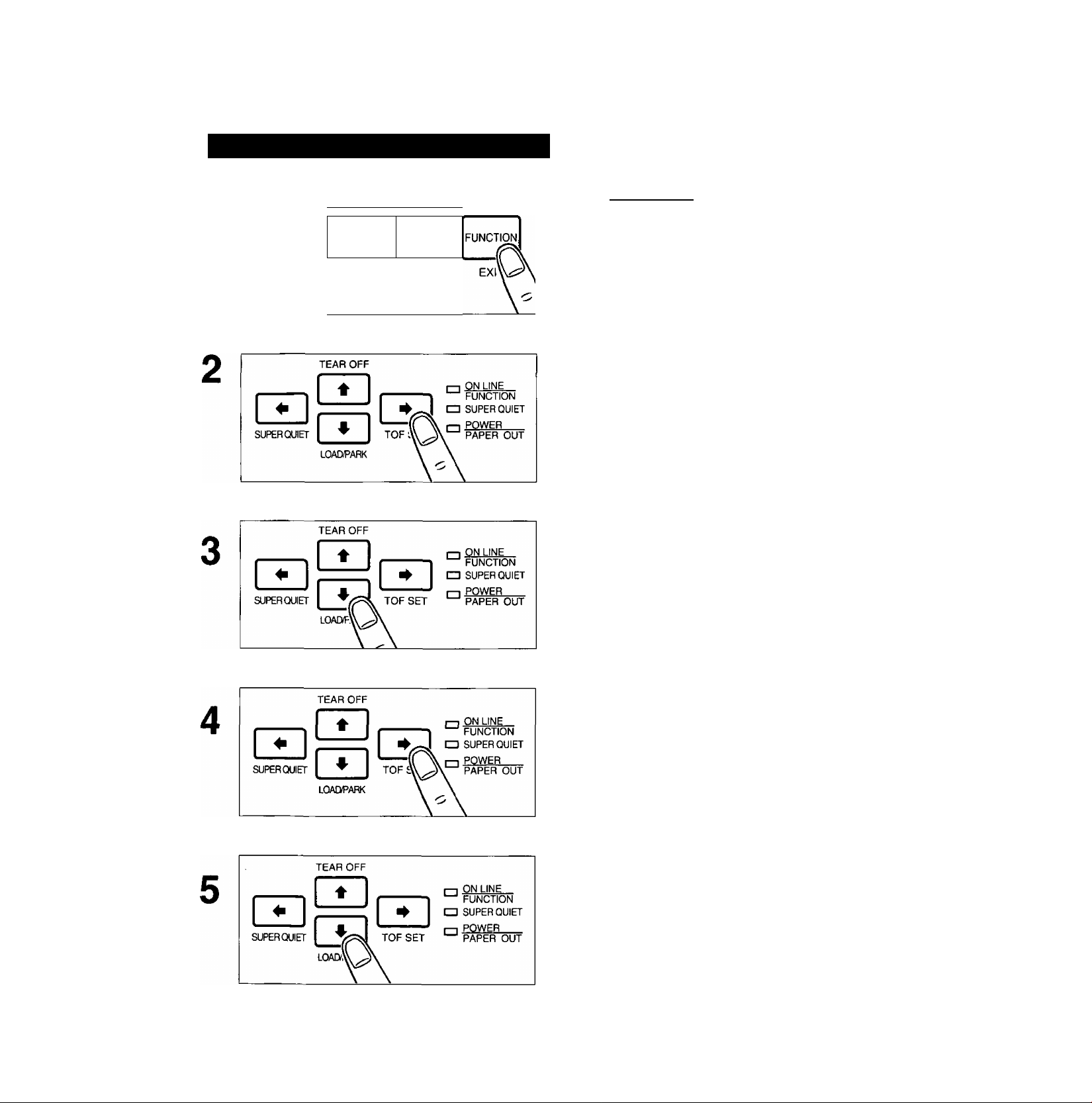
If the ON LINE indicator is blinking,
1
press (FUNCTION] to exit the Function
mode.
Be sure the paper feed selector is in the
“0 PUSH” position.
Press (T] (TEAR OFF) to advance the
paper to the tear bar.
Fold the smoked plastic cover forward
by lifting the tab on right side.
44
Page 45

RaaiBDiig
Tear off the page, using the tear bar.
Press [T] (TEAR OFF) again to reverse
the paper back to the top of form.
—A Top of Form setting (0^ P. 50) past the print
able area is ignored by Tear Off. Tear Off will
use the Top of Form setting that was last saved.
—If you do not press (T] (TEAR OFF) the second
time, once data is received, the printer will auto
matically reverse the paper to the top of form
position.
Replace the smoked plastic cover.
c
S2.
5'
<Q
3*
(D
3
(D
45
Page 46

Paper Parking (Rear feeding only)
This function allows you to use single sheets or envelopes without removing or wasting your fanfold
paper.
Parking the Fanfold Paper
Be sure power is on and the paper feed
1
selector is in the “Q PUSH” position.
c
»
5'
(O
(D
"D
5'
(D If the ON LINE/FUNCTION indicator is
blinking, press [FUNCTION].
Tear off the printed page(s) of the fanfold paper being used, (et P. 44—45)
Press (X) (LOAD/PARK) to reverse the
fanfold paper to the parked position.
While the paper is going back, the display shows
"PAPER BACK”, and when the paper is parked,
the display shows “PAPER OUT”, with the PAPER
OUT indicator blinking. If the printer is in the ON
LINE mode, it automatically goes back to the OFF
LINE mode.
46
Page 47

Loading Single Sheets or Envelopes
1
Paper feed
selector
O Move the paper feed selector to the
position.
The display briefly shows “FRICTION”.
0 Fold the smoked plastic cover.
O Raise the top cover to the single
sheet position.
0 Separate the paper guide and load a
single sheet or an envelope.
(q^ P. 33-35 “Single Sheets and En
velopes”)
O Open the paper door.
0 Load a single sheet or an envelope.
([^ P. 35-36 “Single Sheets and En
velopes”)
c
<2
5'
(Q
(D
■0
5'
(D
Press (ON LINE] to enable printing.
The ON LINE indicator will be lit and the display will
show “ON LINE”.
47
Page 48

c
w
5'
(Q
(D
■D
Reloading the Fanfold Paper
When you are finished printing, remove
the sheet from the printer by rotating
the platen knob.
O Lower the top cover for fanfold
paper.
0 Replace the smoked plastic cover to
its original position.
O Close the paper door.
0 Replace the smoked plastic cover to
its original position.
48
Page 49
Move the paper feed selector to the
PUSH” position.
Press (2 (LOAD/PARK) to reload the
fanfold paper to the first print iine.
c
2
5*
(O
(D
“0
5'
!.
49
Page 50

Top of Form Function
This printer allows you to set and store the first print line position and automatically load the paper to
that location. The first print line position (TOF) will remain stored in memory when power is turned off.
The printer can store the 3 different top of form positions depending on the paper feed method
[fanfold paper (0 PUSH), single sheet (Q), and single sheet with the Cut Sheet Feeder option:
KX-PT11].
o
TJ
5’
<D
If necessary, redefine the page length of
1
the paper you are using through your
application software (o^ P. 82, 88) or the
printer’s Function mode (o^ P. 58, 63).
If the ON LINE/FUNCTION indicator is
blinking, press [FUNCTION].
To redefine your paper’s first print posi
tion, it is recommended that you use
your application software. If this feature
is not provided in your software, adjust
the paper position by using Line Feed,
Micro Line Feed, or Reverse Micro Line
Feed, (c^ P. 43)
A page is defined by setting the page length
through the Function Mode or the Software com
mand.
Press [T] (LOAD/PARK) to load the
paper.
50
Note:
• Do not rotate the platen knob, the printer will
not be able to count the number of lines.
Page 51

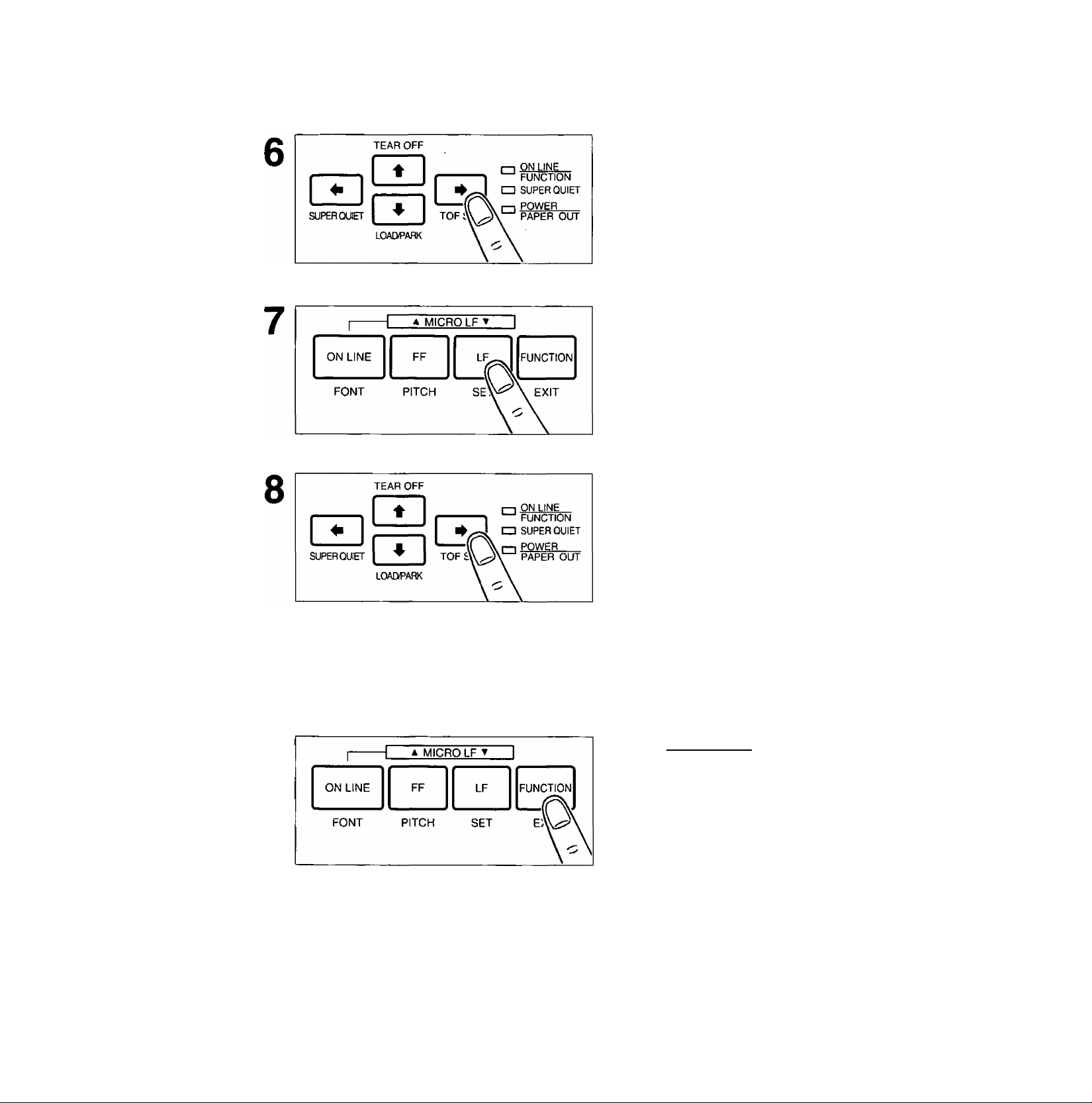
Press @ (TOP SET) to set the Top of Form for the current position.
Saved Top of Form
A Top of Form position (less than or equal to 5"
from the top of page) will be saved even after the
power is turned off. Pressing (2 (LOAD/PARK)
will advance the paper to the most recently saved
Top of Form setting.
Temporary Top of Form
A Top of Form position set in the area greater than
5 inches will not be saved after the power is turned
off, after parking the paper, after using Tear Off, or
after pressing
[fEI when using a single sheet.
Note:
•A temporary Top of Form setting is indicated by one beep. A saved Top of Form setting
is indicated by two beeps.
•When using fanfold paper, the Top of Form position must be set on the first page because the
printer does not accept a top margin which is longer than one page.
C
(0
5'
(O
<D
“O
5'
(D
51
Page 52
You can control a wide variety of printing conditions through the Function mode. The Function mode
is comprised of a Main menu and Sub-menus that allow you to select modes and parameters.
(D3^ P. 58-“69 “Function Mode Menu")
Operation
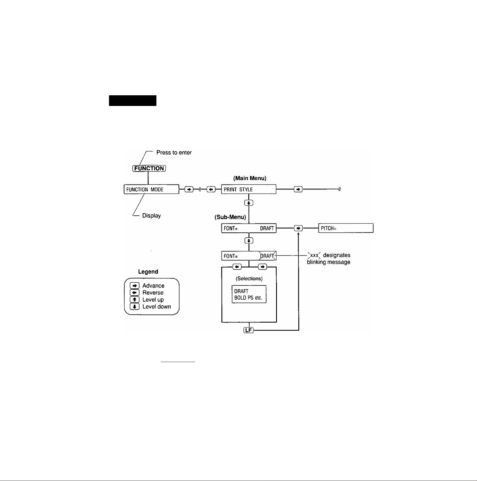
The following flow chart diagrams the operation using the EZ Set Operator Panel. After entering the
Function Mode, the black lettering (FONT, PITCH, SET and EXIT) and outlining (^, t, ^) will
help you navigate through the Main menus, Sub-menus and selections.
3
o
o
a
(D
SE T
Set and returns you to
the Sub-menu
Press (TUNCTioFTl to exit.
52
Page 53
Setting the Function Mode Items
QMfflg ffi© (1§ ©SB
1
I
-------
ON LINE
FONT
1 A MICRO LF T I
■ FF LF
PITCH
Press iFUNCTION) to enter the Func
tion mode.
The display briefly show “FUNCTION MODE" and
the ON LINE/FUNCTION indicator blinks.
SET
Press (3 O'' E) to scroll to the appro
priate Main menu topic (ex; PRINT
STYLE).
Press to enter the Sub-menu.
A status message will appear (ex; FONT=DRAFT)
to reflect the current setting. If you do not want to
change the current setting, skip to step 8 on p. 54.
Press (3 or (3 to scroll to the appro
priate Sub-menu topic (ex; PITCH).
(3 to enter the selection menu.
A status message of your current selection will
blink. ^ ^
(ex; PITCH= NoCP()
c
3
o
o
3
o
a
o
53
Page 54
[UfeGmg ffios ®sG
Press (3 O'" (S to view the other
selections.
A blinking status message will appear as you
scroll through the selections.
Press (L0 (SET) to set the new selec
tion.
The status message will stop blinking and an
equal sign will appear to reflect your new current
selection. If other changes are required at the
Sub-menu level, repeat steps 4~7.
c
3
o
o’
3
o
a
o
10
Press (3 O'' El to make other
changes within the current Sub
menu.
If you do not want to make any other changes,
proceed to step 10.
If changes must be made to another
Main menu topic, press once and
repeat steps 2 through 7.
Press (FUNCTION] to exit the Func
tion mode.
54
•This example can be used for setting any print selection. For direct access to FONT/PITCH,
see page 55 for more details.
•All settings made are temporary unless saved in a Macro.
•Temporary settings are lost when power is turned off.
•The desired settings when power is turned on should be stored as POWER ON MACRO.
Page 55

(1M]D® iii© (Ig ©SG
Direct Access to FONT and PITCH Setting
1
H AMICROLFT I
ON LINE
FONT PITCH
I
-------
ON LINE FF LF FUNCTION
FONT PITCH SET
(For FONT) (For PITCH)
TEAR OFF
SUPER C3UIET
FF LF FUNCTION
SET
1 AMICROLFT I
LOAEiPARK
EXIT
rn ON LINE
FUNCTION
□ SUPER QUIET
POWER
PAPER OUT
.a
Press [FUNCTION] to enter the Func
tion mode.
The display briefly shows “FUNCTION MODE’
and the ON LINE/FUNCTION indicator blinks.
For font, press (ON LINE! (FONT).
For pitch, press fFF| (PITCH).
A status message of your current selection will
appear. ^ ^ ^ ^
(ex; FONT=^DRAFT) (ex; PITCH=NoCPIJ
Press or El to view your desired
font or pitch.
A blinking status message will appear as you scroll
through the selections.
o
3
Press [lFI (SET) to set the new seiec-
tion.
A beep will sound, the status message will stop
blinking and an equal sign will appear to reflect
your new current setting.
Press [FUNCTiON] to exit the Function
mode.
o
a
<0
55
Page 56

ffiDS 1^ ©SG
Setting POINT SIZE
Press [FUNCTION] to enter the Func
tion mode.
The display briefly shows “FUNCTION MODE’
and the ON LINE/FUNCTION indicator blinks.
1
H A MICRO LF ▼ I
ON LINE
FONT PITCH
FF LF
SET
FUNCTION
Press (3 once to select “PRINT STYLE”.
Press (2 to enter the Sub-menu.
A status message will appear {ex; FONT=
c
3
o
DRAFT) to reflect the current setting.
o
a
<D
Press to enter the font selection menu.
A status message of your current selection will
blink.
(ex; FONT=^DRAFTJ
Press (3 or El to select the desired SC font (ex; COURIER-SC).
A blinking status message will appear as you scroll
through the selections.
“SC” is a scalable font.
56
Page 57

QJfeflDO® ffi© ig gsB
Press (lQ (SET) to set the selection.
The display will show “POINT SIZE= 10.5’’.
Press to enter the font selection menu.
A status message of your current point size will
blink.
(ex; POINT SIZE=No.5J
Press @ or ® to select the desired
point size.
A blinking status message will appear as you scroll
through the selections.
Press [L0 (SET) to set the selection.
The display will show your selected point size after
showing “UPDATING CPI" and “UPDATING LPI".
Note:
• If you set a wrong point size, pressing fTl
allows you to make a new selection.
Note:
•When a SC FONT is selected, PITCH will be changed to “PROPORTION" (Proportional
Spacing) and LINES/INCH will be changed to “SC” automatically.
c
3
o
5‘
3
o
Q.
<D
57
Page 58

010
You can control a wide variety of printing conditions through the Function mode. The Function mode
is comprised of a Main menu and Sub-menus that allow you to select modes and parameters by
using the EZ Set Operator Panel or the Setup Disk.
c
3
o
5‘
3
3
o
a
(D
Function Mode Main menu Sub-menu
PRINT SEHING
([^P. 61)
PRINT STYLE
(D^P. 61)
H---------- EMUUTION -[T]- EMUUTION^ EPSON -(T)- EPSON
([^ P. 63)
I®
--------
PAGE FORMAT -QD“ LINES/INCH= 6 -(T>
(11^ P. 63)
-{T]- F0NT= DRAFT "(D-
POINT SIZE=
(®- PITCH= 10 CPI -[T>
Selection
■ffl (All)
-fLFl (Current)
SET
® s
DRAFT SCRIPT
BOLD PS SUPER LQ
COURIER
OCR-B COURIER-SC
ORATOR
PRESTIGE ROMAN-SC
ROMAN S.SERIF-SC
SANS SERIF
—m—j 8 to 96 with 10.5 and 21
10.5
The number increases or
decreases by 2.
10 CPI
12 CPI 5 CPI
15 CPI
17 CPI 7.5 CPI
20 CPI 8.5 CPI
1 3 6 10
4
1.5
2
4.5
2.5 5
BOLD PS-SC
PRESTIGE-SC
SCRIPT-SC
PROPORTION
6 CPi
IBM
7.5
8 SC
9
12
-m
SET
m
SET
SET
SET
SET
(Continued)
• Factory Settings are indicated in
the Sub-menus.
*’“POINT SIZE” will be displayed
only when a SC font is selected in
the FONT Sub-menu.
*2“SC” will be displayed only when a
SC font is selected in the FONT
Sub-menu.
*^The value number depends on the
CPI which has been selected.
58
¡30- P. LENGTH = 11.00" -(Ty-
(Page length)
®-|t. MRGN= 0.00" 1-(TH 0 00" to 2.50"
(Top margin)
30- B. MRGN= 0.00" -(Ty-
(Bottom margin)
L. MRGN= 0/10 CPi
(Left margin)
-CT>
(30- R. MRGN= 80/10 CPI -(T)-
(Right margin)
(®-| CTR PRINTHEAD= 40 |-(®H ^0 to 45 I—(TF)
(Centering)
O.T' to 14.9" with 11.66"
The number increases or
decreases by 0.1.
-[LF]
SET
-(LF)
The number increases or
decreases by 0.05.
0.00" to 4.90" —
0 to 88/10 CPr" I—(LF)
0 to 90/10 CPr^ 1—0
The number increases or SET
decreases by 1.
SET
SET
SET
SET
Page 59

RffilSuQsn]
Function Mode
Main menu Sub-menu Selection
PRINT MODE
((^ P. 64)
TEXT ENHANCEMENT -(T]- B0LD=
—TT1~[ G.D1RECTI0N= UNI [-[Tl— UNI (Unidirectional print)
(Graphic direction)
T,DIRECTION= 81 j Bl (Bidirectional print)
(Text direction)
- PRINT WIDTH^
PANEL LOCK= OFF
8" ~[±}-
OFF -CEh
Bl (Bidirectional print)
UNI (Unidirectional print)
8" 9"
-s>
OFF PITCH ALL
FONT F&P
OFF ON
(0^ P. 65)
DBL HIGH= OFF -[T> OFF ON
(Double high)
ra- DBL STRIKE= OFF -{JJ- OFF ON
(Double strike)
DBL WIDE= OFF -(T> OFF
(Double wide)
® s
ON
-[LF)
SET
■CkE)
SET
-dE)
SET
SET
■0
SET
-(LF)
SET
m
SET
-dE
SET
s-
CHARACTER SET “CD- COUNTRY= USA -(Th
(B^ P. 66)
(Continued)
• Factory Settings are indicated in the
Sub-menus.
^’“ITALIC” is available only in the EPSON
mode.
- ITALICS=
OFF -CD- OFF
t
OUTLINE=
SHADOW=
ZERO FONT= NORMAL -I
CDH CHR SET= ITALIC 1-CDH ITALIC
(Character set)
CODE PAGE= US^®-fuSA
OFF -[Th OFF
OFF -CDh
♦ H NORMAL POINT
ON
ON
OFF
SLASH
USA LTN AMER
DENMARK1
DENMARK2 LEGAL
FRANCE
GERMANY SPAIN1
ITALY SPAIN2
JAPAN SWEDEN
KOREA UK (England)
GRAPH1 (Graphic 1)
GRAPH2 {Graphic 2)
C.FREN (Canada French)
MULT (MuStilingual)
NORWAY
PORT (Portugal)
TURKEY
ON
(Later America)
NORWAY
-dE
SET
-dE
SET
-dE
SET
-dE
SET
-dE
SET
-dE
SET
-dE
SET
59
Page 60

Function Mode
ra
Main menu Sub-menu Selection
INSTALL “(Tl- AGM/IBM=
(0^ P. 67)
(Alternate Graphic Mode)
OFF -ffl“
OFF ON
SS
-m
SET
c
3
o
5‘
3
o
Q.
(D
I- AUTO CR/I8M= OFF “S“
J-| AUTO LF=
^2i
------------
AUTO L0ADING= ON “(T]“ ON
8UZZER=
- P.0.DETECT= ON -{T}- ON OFF
(Paper Out detector)
QUIET M0DE= OFF
SH REV LF/PULL= OFF -CT]~jO^
(Reverse Feeding
in PULL Mode)
Si TEAR 0FF= MANUAL KiDi MANUAL AUTO |—EE
)- CSF M0DE= OFF -[£}- OFF
(Cut Sheet Feeder Mode)
D0WNL0AD=
C0L0R=
OFF “S“ OFF
ON -(T]- ON
-ffl-
OFF
-53-[ot
BLACK
-CD-
OFF ON
ON
OFF
OFF
OFF ON
ON
ON
ON
BLACK ORANGE YELLOW
BLUE RED
GREEN VIOLET
-EE
-m
SET
-ClE
SET
-[LF]
SET
m
SET
-m
SET
-[lE
SET
-(lE
SET
SET
SET
-EE
SET
-EE
SET
S’
s-
s-
DISPLAY LANGUAGE “S“ LANGUAGE= ENGLISH
INTERFACE
MACRO MODE
• Factory Settings are indicated in the
Sub-menus.
^'Effective in the IBM mode only.
^^Ineffective when using the Cut Sheet
Feeder.
*^“SERIAL" is effective only when the
optional KX-PS14, RS-232C Serial in
terface board is installed.
60
(1^ P. 69)
([^ P. 69)
((^ P. 69)
ENGLISH SPANISH
FRENCH
GERMAN TURKISH
l/F=
D.LENGTH= 8 BIT “E“
(DATA Length)
H SAVE MACR0= #1 HSH #1 #2 #3 #4 |—EE
POWER ON MACR0=1 “S"
PARALLEL “S“
8 BIT 7 BIT
#1
#2 #4
1 3 F
2 4
ITALIAN
PARALLEL SERIAL"^ j—EE
-EE
#3 FCTRY
(Factory setting)
(Factory setting)
-EE
-EE
SET
SET
SET
SET
SET
-EE
SET
Page 61

H!DDD§iBa]Q
PRINT SETTING Menu
(To Print Out the Function mode Settings)
Before you change the Function mode settings, you can verify the settings by printing them.
To print...
Current settings only—Press [L0 (SET) after selecting the PRINT SETTING Main menu.
All settings (current, MACROS and Factory)—Press after selecting the PRINT SETTING Main
menu.
PRINT STYLE Menu
(To Change the Font/Pitch)
FONT
This Sub-menu in the PRINT STYLE Main menu will allow you to select and set a desired font. This
printer has draft, 8 LQ (Letter Quality), 1 Super LQ fonts and 6 scalable fonts. Draft is printed at the
fastest speed and is normally used for printing draft documents. LQ produces the high print quality
and SLQ produces much better print quality than LQ; they are used to print the final version of formal
documents. If you want to see all of the font samples, use the Self Test feature on page 39.
(Print Example)
Draft:
ABCDEFGHIJKLMN0PQRSTUVWXYZ0123456789
abcdefghijklmnopqrstuvwxyz
Bold PS:
ABCDEFGHIJKLMNOPQRSTUVWXYZ0123456789
abcdefifhi jklmnopqrstuvwxyz
Courier:
ABCDEFGHIJKLMNOPQRSTUVWXYZ0123456789
abcdefghi jklmnopqrstuvwxyz
OCR-B:
ABCOEFGHIJKLMNOPQRSTUVWXYZO123456789
abcdefghijk Lmnopqrstuvuxyz
Orator:
ABCDEFGHIJKLMN0PQRSTUVWXYZ0123il56789
ABCDEFGHIJKLMNOPQRSTUVWXYZ
Prestige:
ABCDEFGHIJKLMNOPQRSTUVWXYZ0123456789
abcdefghijklmnopqrstuvwxyz
Roman:
ABCDEFGHIJKLMNOPQRSTUVWXYZO123456789
abcdefghi jklmnopqrstuvwxyz
Sans Ser i f:
ABCDEFQHIJKLMNOPQRSTUVWXYZO123456789
abcdefgh i jkImnopqrstuvwxyz
c
3
o
5'
3
o
a
(D
A8COEFGHrJKLMNOPQRSrUVWXyZ01234567S9
at give j Ivimno z
Super Letter Quality (Roman):
ABCDEFGHIJKLMNOPQRSTUVWXYZO123456789
abcdefghi jklmnopqrstuvwxyz
61
Page 62

(SffiûSOflSïB
PITCH
The Sub-menu in the PRINT STYLE Main menu will allow you to select and set a desired pitch. This
printer has 10 pitch selections.
The height of the characters in the different pitches is the same; only the width varies. The pitches are
fixed pitch {within a pitch, all characters have the same width).
In proportional spacing, character widths vary with the character. An “I”, for example, takes up less
space than an “M” or a “W". Proportional printing gives the document a typeset appearance.
The following tables shows pitch availability for each font.
Font
Draft
Bold PS
Courier
OCR-B
Orator
Prestige
Roman
Sans Serif
Script
SUPER LQ
OCR-B micron prints using the Sans Serif font.
{Print Example)
5 6 7.5 8.5
О о о О
О о
о о
о о
о о
о о
о о
о о о
о о о
о
5 c:p± E>r-±ntinsr
О
CPicrsi elonerated.)
О о о о о
О о о о о
•
о о о
О о о о о
О о о о о о о
О о о о о о о
о о О о о о о
о о О о о о о
6 cpi printing
(Elite elongated)
7 . cp± |p]riir\%±ng
( C XT on a 1 OY>9 A ^ Ad )
8.5 cpi printing
(Compressed elongated)
10 cpi printing (Pica)
12 cpi printing (Elite)
13 cpi printing (Hlcron)
IT cpi piintiag (Coipressed)
TO cpi piloting {Elite Covrened)
Proportional Spacing
10
12
15 17 20 PS
о о о о о
о о о
о о о
•
о о о
о о о
о О
о
о
62
• For direct access to font and pitch settings, see page 55.
•To override your software with these two features (FONT and/or PITCH) activate the above
setting(s); see “PANEL LOCK”, P. 64)
POINT SIZE
You can alter the point size to make a font larger or smaller only when the scalable font (BOLD-SC,
COURIER-SC, PRESTIGE-SC, ROMAN-SC, SANS SERIF-SC and SCRIPT-SC) is selected in the
FONT Sub-menu.
When a SC font is selected, PITCH will be changed to “PROPORTION" (Proportional Spacing) and
LINES/INCH will be changed to “SC” automatically.
Page 63

RiffiDSiMiD (iil5^
EMULATION Menu
(To Change Your Printer’s Emulation)
This printer can emulate the Epson LQ-570 or the IBM Proptinter X24E.
P. 38 “Printer-Driver Selection")
PAGE FORMAT Menu
(To Change the Lines Per Inch/Page Format)
LINES/INCH This Sub-menu in the PAGE FORMAT main menu will allow you to change lines per inch.
Note:
•When a SC font is selected in the FONT Sub-menu, lines per inch will be changed to “SC”
automatically. The value of “SC” will be changed by the point size and the most suitable
space between the lines for the each point size is set up. You can change the lines per inch
within even if a SC font is selected.
Page formating is determined by:
© Page length (P.LENGTH)
(2) Top margin (T.MRGN)
@ Bottom margin (B.MRGN)
@ Left margin (L.MRGN)
© Right margin (R.MRGN)
I I
-H @ Left margin |
I
© Right margin
•The center position default is 40. If you have shortened your printable area, you may want to
reposition your printhead to a new centered position. This is accomplished through the CTR
PRINTHEAD Sub-menu in the PAGE FORMAT Main menu.
c
(5
E
Q.
O
c
p
n
E
E
o
o
CD
® ©
_l
0.
O)
c
(U
0
O)
CO
63
Page 64

ISlDDiXSiMjD (Möxa§
Note;
•When changing the left/right margins, / (3 moves the carriage right or left.
Pressing (5]! (3 when the carriage reaches the end of the platen moves it to the opposite
end.
• If the left margin is set to the right of the right margin, the right margin is reset to 80 {10 cpi)
automatically.
•The skip perforation command overrides the front panel bottom margin setting.
•When the PRINT WIDTH is changed, the left margin will default to 0" and the right margin will
default to 8" or 9" automatically depending on your selection of the print width. Please refer to
chart on page 97 for the maximum number of characters per line according to your pitch
selection. To change the print width to either 8" or 9", refer to “PRINT MODE Menu” (in this
page).
PRINT MODE Menu
(To Change Print Direction etc.)
This printer allows you to select print direction in graphics and text modes.
When you print graphics such as tables, set the G.DIRECTION Sub-menu to UNI. The printer will
print left-to-right only and provide precise vertical alignment. Setting to Bl will print in both directions
and reduces printing time, however the vertical alignment may not be as precise.
c
3
o
5’
3
o
a
(D
PRINT WIDTH
This Sub-menu in the PRINT MODE Main menu will allow you to change the print width to either 8"
or 9".
PANEL LOCK
This Sub-menu in the PRINT MODE Main menu will allow you to decide the priority between the
printer’s front, panel settings and the software commands. This PANEL LOCK Sub-menu is set to
OFF when shipped which allows the software commands to override the printer’s front panel settings.
To activate the printer’s
Font only—Set PANEL LOCK=FONT
Pitch only—Set PANEL LOCK=PITCH
Font and Pitch only—Set PANEL LOCK=F&P
All settings—Set PANEL LOCK=ALL
Note:
•When you set a SC font in the FONT Sub-menu and “FONT” in the PANEL LOCK Sub-menu,
PITCH will be changed to “PROPORTION” (Proportional Spacing) automatically.
64
Page 65

RnMBajD Gfils^
TEXT ENHANCEMENT Menu
(To Enhance Your Text)
This printer allows you to have a variety of print styles using this Sub-menus.
Any enhancements can be set to ON (enable) or OFF (disable).
Enhancements are independent and are set individually, therefore, any enhancement can be
combined with another.
Double high printing makes the height of a character twice that of a normal one.
Double wide printing makes the width of a character twice that of a normal one.
Double strike printing uses a double strike with two passes of the printhead.
Bold (Emphasized) printing is done with one pass of the printhead at half speed, which allows
horizontally adjacent dots to be printed.
Outline printing makes the outline character of a normal one.
Shadow printing makes the shadow character of a normal one.
Italic printing makes a character slope from the right downwards.
(Print Example)
Emphasized Printing
Double High
Double Strike Printing
Dovilole Wide
Italic
Shadow Printing
ZERO FONT
This mode will allow you to set one of the following zero font selections.
Numeral “0" and alphabet “0” are very similar. To easily distinguish between them in a document,
print “0” or “0" instead of normal zero. Select and set one of the following in the ZERO FONT
Sub-menu.
Selections
Printing
Zero font
c
3
o
o'
3
o
a
(D
NORMAL
POINT
SLASH
When the international character set is set to Norway, zero slash is printed as 0.
0
0
0
65
Page 66

(MïïDiXSiMjD GiaaSs
CHARACTER SET Menu
(To Change the Character Set)
COUNTRY
This Sub-menu in the CHARACTER SET Main menu will allow you to set one of the following
international character set selections.
c
3
o
5‘
3
o
a
<D
Selections
USA
DENMARK1
DENMARK2
FRANCE
GERMANY
ITALY
JAPAN
KOREA
CHR SET
This Sub-menu in the CHARACTER SET Main menu will allow you to set one of the following
character set selections.
Selections
ITALIC
GRAPH1
GRAPH2
CODE PAGE
This Sub-menu in the CHARACTER SET Main menu will allow you to set one of the following code
page selections.
Character set
USA
Denmark 1
Denmark 2
France SPAIN1
Germany
Italy
Japan
Korea
Character set
Italic
Graphic 1 Epson or IBM mode
Graphic 2
Selections Character set
LTN AMER Latin America
LEGAL
NORWAY
SPAIN2 Spain 2
SWEDEN Sweden
UK
Epson mode only
Legal
Norway
Spain 1
England
66
Selections
USA
C.FREN
MULT
Code page
USA
Canadian French PORT
Multilingual
Selections Code page
NORWAY
TURKEY
Norway
Portugal
Turkey
Page 67

(R!!InX§[M)D (Mais
INSTALL Menu
(To Control Initial Setup Conditions)
Alternate Graphics Mode
The alternate graphics mode (AGM) will allow you to selects Epson graphics while in the IBM mode.
Sub-Menu Selections Function
AGM/IBM ON
OFF
Sets Alternate Graphics Mode
Releases Alternate Graphics Mode
Automatic CR
Sub-Menu
AUTO CR/IBM
Selections Function
ON Activates Automatic CR on LF, VT, ESC+“J”
OFF Prevents Automatic CR on LF, VT, ESC+“J”
Automatic LF
Sub-Menu Selections Function
AUTO LF ON
OFF Activates CR only
Activates CR+LF
Automatic Paper Loading
When the AUTO LOADING Sub-menu is ON, the printer automatically loads a single sheet or an
envelope to the first print line.
■n
c
3
o
5’
3
o
a
(D
Buzzer Sound Controi
Select and set ON (sounds) or OFF (no sound) in the BUZZER Sub-menu.
Paper Out Detector
When the P.O.DETECT Sub-menu is ON, the printing stops once the paper is no longer under the
platen.
To avoid this and print to the end of the paper, set the P.O.DETECT Sub-menu to OFF.
67
Page 68

RiddosìM) GSteéte
INSTALL Menu
Super Quiet Printing
This feature reduces printing noise, however, it also reduces the printing speed.
Select and set ON (activate) or OFF (deactivate) in the QUIET MODE Sub-menu.
Reverse Feeding in Pull Mode
When you control reverse feeding in pull mode, select and set ON (enable) or OFF (disable) in the
REV LF/PULL Sub-menu.
Automatic Tear Off
This feature loads the fanfold paper’s perforation to the tear off position automatically.
Sub-Menu Selection Function
TEAR OFF
AUTO Automatic Tear Off
MANUAL Manual Tear Off (using TEAR OFF switch)
Cut Sheet Feeder Mode
CSF MODE
This Sub-menu will allow you to use the Cut Sheet Feeder (ON). This menu should be OFF when not
in use.
(This setting is effective only when the paper feed selector is in “Q” position and C.S.F. option
3
o
(KX-PT11) is installed. ((®° C.S.F. manual)
Download Buffer Control
o
Q.
(D
If you need to download special characters, set the DOWNLOAD Sub-menu to ON. By setting the
Sub-menu to OFF, more data can be sent to your printer’s buffer, thereby freeing up your computer.
Color Printing
Before you use this function, make sure that the color kit (KX-PCK11) is installed in the
printer. ([^ The color kit manual)
COLOR
Your desired print color may be selected through the front panel or through your application software.
68
Note:
•The appropriate driver must be selected in the application software which supports color.
Refer to page 38 for Printer-Driver Selection information.
• Only one color can be printed at a time.
Multi-color printing may be accessible through your application software.
Page 69

HaoiisuOaiD
DISPLAY LANGUAGE Menu
(To Select the Display Language)
Select and set one of the six display languages in the LANGUAGE Selection.
INTERFACE Menu
(To Select Interface)
The INTERFACE menu allows you to select the appropriate method of communication (parallel/se-
hal) with the computer.
To activate serial communication, you must first install the KX-PS13 or KX-PS14 serial interface.
With the KX-PS13 installed, the parallel interface is deactivated.
MACRO MODE Menu
(To utilize the MACROS)
A MACRO allows you to store a combination of your most frequently used print conditions {all settings
in the Function mode) into the printer’s memory which can be easily recalled and/or changed. This
will enable you to recall one of 4 combinations (MACROs #1, #2, #3, #4) at the touch of a button
eliminating the need to reset all your frequently used features.
SAVE MACRO
The SAVE MACRO is a Sub-menu in the MACRO MODE Main menu. This mode will allow you to
save your current customized printing requirements to any SAVE MACRO (#1, #2, #3 or #4)
selection. To load (recall) your customized macro select the same number in the LOAD MACRO
Sub-menu.
LOAD MACRO
The LOAD MACRO is a Sub-menu in the MACRO MODE Main menu. This mode wilt allow you to
recall your current customized printing requirements from any LOAD MACRO (#1, #2, #3 or #4)
selection.
POWER ON MACRO
The POWER ON MACRO is a Sub-menu in the MACRO MODE Main menu. This mode will allow you
to automatically recall a desired MACRO or FACTORY setting each time you turn on the printer.
FACTORY setting (Default setting): All the original settings in the Function mode can be restored
in the printer, as they were originally set when the printer was shipped. However, it does not change
any of the settings which are stored in MACRO #1, 2, 3 or 4. To do so, recall the Factory setting, and
save each Macro one at a time.
69
Page 70

Moigl §sífea[g [Ditefe
This Setup Disk can only be used in an IBM-PC or a compatible computer with a 3.5" floppy disk drive.
Before you use the Setup Disk, it is recommended that you make a back-up copy and store the
original in a safe place.
This printer has been factory set to operate with most of the popular software packages. In
most cases there will be no need to change the Function mode items. Refer to pages 58—60
to verify that the factory settings meet your requirements. If no changes are required, you
should be ready to print.
Note:
• Use the DISKCOPY command of the operating system to make a back-up copy. Refer to your
DOS manual for further information.
•You may find it convenient to install the Setup Disk programs directly onto your C Drive, rather
than reading them from the Setup Disk each time a change is necessary. Either method is
acceptable.
To perform an automatic installation of the Setup Disk files onto your C Drive, follow the steps
below:
1. Insert the Setup Disk into drive A or B.
2. Type A: {or B:) and press Enter.
3. Type INSTALL and press Enter.
C
3
o
5‘
3
S
o
Q.
(D
This procedure automatically creates a directory called 3124 and copies all of the programs
from your Setup Disk onto your C Drive.
At your C:\> prompt, type CD 3124 and press Enter.
Type SETUP and press ( Enter 1 to complete the procedure. Be sure to type this
instruction as one word.
If not, you will receive a Syntax error message.
Running the Setup Program
Insert your Setup Disk into either drive A or B.
1
<For Dos>
Type A: (or B:) and
2
press ( Enter),
Type SETUP
3
<For WINDOWS>
Select Run from the File
2
menu.
Type A:\SETUP
3
(or B:\SETUP)
70
Press ( Enter).
4
You will receive a “Please wait!I” message
until your first screen automatically appears.
Click I OK I (or Press ( Enter]).
4
Page 71

QMn® ffl© (IM^
The first screen is an introduction to the operation of the Setup Disk.
Please read it through and press any key to continue.
The <Menu> window will
be highlighted.
Note:
•You can proceed through the
Setup Disk using a computer
mouse or your arrow keys.
^ < Menu >;
GeRINTlSTyLEl
-.EMULATION
.PAGE FORMAT
.PRINT MODE
.TEXT ENHANCEMENT
.CHARACTER SET
.INSTALL
.DISPLAY UNGUAGE
.INTERFACE
.POWER ON MACRO
<< Setup Utility [XXXXXXKXXXX) »
F < Item > -
FONT
PITCH
•[ESC] exits you to DOS when
you are at the <Menu> window.
Using the keyboard:
•m / (3D to move within the
current window.
•(3) to advance to <)tem> and
<Setting> windows.
« COMMENT »
Select print style
« KEY OPERATION » =
[F1=HELP]
[F2-FACTORY SETTINGS]
[F3=SAVE TO DISK]
]F4=LOAD FROM DISK]
[F5=PRINT SETTINGS]
[F10-SENDTO PRINTER] 1ESC = EXIT]
•[Enter]to make selection in
<Setting> window.
•(3 to return to previous
window.
Using the mouse:
• Highlight the selection and click
the left mouse button.
•Click the right mouse button to
move to the previous screen.
Print Settings
Before you change any selections on the Setup Disk, you can verify the settings by getting a print-out.
c
3
o
o'
3
o
Q.
(D
Press CE^.
1
A Print Setting window will be
displayed.
Press [a) O'' ©) O'' high
light the appropriate com-
mand and press [ Enter).
“A”: All the settings (current,
MACROS, Factory)
will be printed.
“C": Current settings will be
printed.
If you do not want a print
out of your settings, press
(US-
:< Menu >:____
Gf?R!NT-STYLEl
.EMULATION
.PAGE FORMAT
.PRINT MODE
.TEXT ENHANCEMENT
.CHARACTER SET
.INSTALL
.DISPLAY LANG
.INTERFACE
.POWER ON Mfi
« COMMENT » :
Select print style
« KEY OPERATION >>:
<< Setup Utility (xxxxxxxxxxx) >>
F < Item >:
FONT
PITCH
Please select PRINT SETTING (AiC)
[CURRENT]
r[F5=PRINT SETTINGS] t
[ESC=EXIT]
71
Page 72

OMifl® ®Q3 ©3Q]qp (Mis
Setting Selections on Setup Disk
1
c
3
o
5*
3
o
Q.
o
In the <Menu> window, press [T] or m.
Select the desired menu
(ex; PRINT STYLE).
Press @.
<ltem> window will be highlighted.
Press [T] or .
Highlight the desired item
(ex; FONT).
Press @.
<Setting> window will be
highlighted.
Press C±] or (X) ■
< Menu >:
CipniNrsTyLE;
^EMULATION
*PAGE FORMAT
♦ PRINT MODE
♦ TEXT ENHANCEMENT
♦ CHARACTER SET
♦ INSTALL
♦ DISPLAY LANGUAGE
♦ INTERFACE
♦ POWER ON MACRO
« COMMENT » =
Select font style
Style of typeface.
SC is SCALABLE FONT.
« KEY OPERATION » =
[FI = HELP]
[F2 = FACTORY SETTINGS]
<< Setup Utility (xxxxxxxxxxx) »
[F < item >:
Cfont_
PITCH
[F3=SAVE TO DISK]
[F4=L0AD FROM DISK]
f < Setting > ♦
V[DRAirrJ
[F5-PRINT SETTINGS]
[F10=SEND TO PRINTER] [ESC = EXIT]
BOLD PS
COURIER
OCR-B
ORATOR
PRESTIGE
ROMAN
SANS SERIF
SCRIPT
SUPER LQ
BOLD PS SC
COURIER SC
PRESTIGE SC
ROMAN SC
SANS SERIF SC
SCRIPT SC
72
Highlight the desired setting
(ex; BOLD PS).
Press {Enter ].
The desired item has been set.
A V will appear next to the
new setting.
Page 73

Press ®.
<ltem> window will be
highlighted.
To make additional changes in
the <ltem> window, repeat
steps 3 to 6.
Press ©.
8
<Menu> window will be
highlighted.
(№BQi© (IS©
10
11
To make additional changes in
the <Menu> window, repeat
steps 1 to 6.
When all changes have
been made, you may
perform any one of the
following operations:
•Save to Disk—IF3) (0^ P. 74)
•Print Settings—fF^ {(^ P. 71)
•Send to Printer—[ F1Q1 ((^ P. 75)
After performing one of
the above operations,
and with the <Menu>
window highlighted,
press f ESCl.
Press [y] or ® •
“Y": You have exited the Setup
program.
“N”; The display will return to
the <Menu> window.
fp < Menu > :
GpniNT.'STyCE'
* EMULATION
»PAGE FORMAT
»PRINT MODE
»TEXT ENHANCEMENT
»CHARACTER SET
»INSTALL
»DISPLAY UNG
»INTERFACE
»POWER ON M^
<< COMMENT » :
Select print style
« KEY OPERATION »=;
[FI-HELP]
[F2=FACTORY SETTINGS]
<< Setup Utility {xxxxxKxxxKK) >>
fp < Item > :
FONT
PITCH
[F3=SAVE TO DISK]
[F4=LOAD FROM DISK]
[F5-PRINT SETTINGS]
[F10-SEND TO PRINTER] [ESC-EXIT]
a
(D
73
Page 74

CMS© ©saiqp (110@te
Save to Disk
Press [ F3 ].
1
A Save to Disk window will be
displayed.
Enter a file name (up to
8 characters, upper or
lower case).
Press [ Enter).
All the settings will be saved
on the disk and the display
will return to the <Menu> window.
Press [ESC], [Y] to exit to DOS.
3
o
o’
3
o
a
(D
Load from Disk
Press [~F4).
1
A Load from Disk window will be
displayed.
Use [T] or [T] to highlight
your desired file name.
Press [ Enter ].
All the settings in the file
will be loaded to your screen.
To transfer these settings to your
printer, you must perform the
(Ftp]Send to Printer operation:
(B^ P. 76)
rf < Menu > =
□ PRINTjSTyi:E_
+EMULATION
*PAGE FORMAT
*PRINT MODE
tTEXT ENHANCI
♦ CHARACTER S
»INSTALL
♦ DISPLAY LANG
♦ INTERFACE
»POWER ON Mfi
« COMMENT » :
Select print style
« KEY OPERATION »:
__
<< Setup Utility (xxxxxxxxxxx) >>
F < Item > -
FONT
PITCH
File name : (I i to highlight; Enter)
I xxxx.DAT 1
xxxxxxxx.DAT
xxxxx.DAT
xxxxxx.OAT
XXX. DAT
[[F4=LOAD'FROM DISK)!
[ESC=EXIT]
74
Page 75

Send to Printer
(yfeflDiig) ffl© ©saoq«)
Press (F10].
1
A Port Selection window will be
displayed.
Press [T] Of ® ■
Select the desired Port selection
item (ex; PORT).
Press @.
A Selection window will be
displayed.
Press [T] or [T] •
Highlight the desired setting
(ex; LPT1).
Press [ Enter).
The desired item has been set.
, < Menu >:
DiPRlNTjSTyLEl
+EMULATION
+PAGE FORMAT
+PRINT MODE
»TEXT ENMANCEMI
»CHARACTER SET
»INSTALL
»DISPLAY LANGUA
»INTERFACE
»POWER ON MACF
« COMMENT » :
Select print style
« KEY OPERATION >>:
< Menu >
DtERINT.'STyLE
»EMULATION
»PAGE FORMAT
X PRINT MODE
»TEXT ENHANCEMI
»CHARACTER SET
»INSTALL
»DISPLAY LANGUA
»INTERFACE
»POWER ON MACF
« COMMENT >>:
Select print style
« KEY OPERATION »:
<< Setup Utility (xxxxxxxxxxx) »
F < Item >:
[ceont:
Port selection
PORT : lEPXr]
BAUD RATE
PARITY
DATA LENGTH
PROTtXOL
Send to printer (Y/N)
[YES] [NO]
<< Setup Utility (xxxxxxxxxxx) >>
Port selection
PORT
BAUD RATE
PARITY
DATA LENGTH
PROTOCOL
Send to printer
]YES] |N0]
: [9600 )
: [NONeI
: [6bit ]
:[OTR ]
|LPTr]|
: [9600 j
: (NONE)
: (Bbit 1
;(DTR 1
(WN)
W-
[2: LPT2)
[3: LPT3]
[4:
[5:
(6:
[[FlQgSENDlTO'PRINTERlI [ESC- EXIT]
!j1: LPTIll
[2: LPT2]
[3: LPT3)
[4: C0M1]
[5: COM2)
[6: COM3]
|1F10-SENP;TO'PRINTER]1[ESC=EXIT]
UPTDl
C0M1)
COM2]
COM3]
t i
c
3
o
5‘
3
o
a
(D
Press ®.
To make additional changes in
the Port Seletion menu, repeat
steps 2 to 5.
75
Page 76

CMiOg iiii© ©saiq») (1)^
Press [T] until YES is
highlighted.
Press [Y] or [N] .
8
"Y”: All the settings will be sent
to the printer.
"N”: The display will return to
the <Menu> window.
Press [ESC], [Y] to exit to
DOS.
FACTORY Setting
< Manu >:
PRINT STYLE'
«EMULATION
«PAGE FORMAT
«PRINT MODE
«TEXT ENHANCEM
«CHARACTER SET
«INSTALL
«DISPLAY LANGUA
«INTERFACE
«POWER ON MACF
« COMMENT » :
Select print style
« KEY OPERATION » =
« SeUp Utility (xxxxxxxxxKx) »
< Item >:
FONT
It
Port selection
PORT
BAUD RATE
PARITY
DATA LENGTH
PROTOCOL
Send to printer (YiN)
[[VESn [NO]
[LPT1)
[9600]
[NONE)
[Bbit]
(DTR)
[[F10~5ENOTO~PRINTER1|(ESC°EXIT]
C
3
o
5*
3
S
o
Q.
(D
Press
1
Press [y] or [N] .
“Y": All the screen settings will
be reset to the FACTORY
settings.
"N”: The display will return
to the <Menu> window.
If [Y] was selected, you
may perform one of the
following operations:
• Save to Disk —(l^ P. 74)
• Print Setting —fFTl (i^ P. 71)
• Send to Printer —[ FI 01 ([@^ P. 75)
Press [ESC], (y) to exit to
DOS.
f? < Menu >:
QF^RINt STYLE'
«EMULATION
«PAGE FORMAT
«PRINT MODE
«TEXT ENHANCEMENT
«CHARACTER SET
«INSTALL
«DISPLAY LANG
«INTERFACE
«POWER ON M/
« COMMENT »:
Select print style
« KEY OPERATION » =
irF2=FACTORY'5ETTING5]| (ESC-EXIT)
<< Setup Utility (xxxxxxxxxxx) »
F < Item >:
FONT
PITCH
Are you sure ? [Y/N)
[NO]
76
Page 77

Help
If you cannot remember what a particular function does, HELP will show you the explanations of the
functions.
Press [fT].
1
A Help Item screen will be
displayed.
Press ® ® / C±3 /
Highlight your desired item,
(ex; AGM/IBM)
Press fEnter].
A definition will be displayed.
Press (ESC].
The Help Item screen will be
displayed.
Press [ESC].
« HELP ITEM »
L<AGM/IBM^
<AUTO cr;ibm> < EMULATION > < POINT SIZE:;.
<AUTO LF>
<ALTrO LOADING> <G.DIRECTION> <PRINT MOOE>
<BOTTOM MARG!N>
<BOLD>
<BUZZER>
<CHARACTER SET>
<CODE PAGE> <LEFT MARGIN> <REV LF/PULL>
<COLOR> <L1NEANCH> <SERIAL>
<COUNTRY>
<CSF MODE> <PAGE LENGTH>
<CTR PRINTHEAD>
<DOUBLE HIGH>
<DOUBLE STRIKE> <PANEL LOCK> <TEXT ENHANCEMENT>
<DOUBLE WIDE>
<DISPLAY LAN6UAGE>
« KEY OPERATION FOR HELP » =
m
( - ) t - I [ENTER KEY]
<DOWNLOAD>
<FONT>
<tNSTALL>
<interface>
< IT ALIO
<ITALICS>
<OLm.1NE>
<p.o.detector>
<PAGE FORMAT>
<PARALL£L> <ZERO FONT>
<PITCH>
<POWERON MACRO>
<PRINT STYLE>
<PRINT WIDTH>
<OUIET MODE>
<RIGHT MARGIN>
<SHADOW>
<T.DIRECTION>
<TOP MARGIN>
<TEAR OFF>
m
« HELP ITEM »
C<AGM/IBM>]
<AUfb CR/IBM>
<AUTO LF>
<AUTO LOAOlNG>
<AGM/IBM>
The alternate graphics mode (AGM) will allow you to select
Epson graphics while in the IBM mode. If what you printed is
not exactly what is on the screen, but there is a symbol that
is replacing the symbol you expect, change the character set.
•"<<::TFrPffiHTHgACi>—
<DOUBLE HIQH>
<DOUBLE STRIKE>
<DOUBLE WIDE>
<DISPLAY UNGUAGE>
<DOWNLOAD>
<EMULATION>
<FONT>
<G.D|RECTI0N>
“<ir&,DETECT0tl>^
<PAGE FORMAT>
<PANEL LOCK>
<PARALLEL>
< PITCH >
<POIMT SIZE>
<POWER ON MACRO
<PRINT MODE>
<TEAR OFF>
<TEXT ENHANCEMENT>
<ZERO FONT>
[ESC-EXIT]
o
a
(D
The display will return to the
<Menu> window.
« KEY OPERATION FOR HELP » =
III
[ ^ 1 ( -*) [ENTER KEY]
[1]
[ESC=exiT]
77
Page 78

OIO
olorü
This section is for the development of programs and printer drivers and assumes the reader is
proficient in programming. More detailed information has been stored in the Command Reference
program on the Setup Disk. P. 90)
Font Selection
Function Name Parameter
Selects print quality
ESC “x" n
n=0: Draft
n=1; LQ
n=2: SLQ mode (Roman 5, 10, 6, and
12 CPI fonts only)
Selects print typeface
Selects sub/superscript printing ESC "S" n
Releases sub/superscript printing
Selects font by pitch and point
ESC “k” n
ESC “T”
ESC “X" m Hi Hi
Character Pitch Selection
Function
Sets pica pitch (10 cpi) printing
Sets elite pitch (12 cpi) printing* ESC "M"
Sets micron (15 cpi) printing ESC
ESC
“P"
"g"
Name
n=0: Roman n=4: Script
n=1: Sans Serif n=5: OCR-B
n=2: Courier n=6; Bold PS
n=3: Prestige n=7: Orator
n=0; Superscript
n=1: Subscript
0Sm^127 except 2, 3 and 4
m=0: No change to character spacing
1: Character spacing is set to PS
m=
m>4: Sets character spacing to 360/^ cPI
(0^n,g255)cfc (0^n.si27)oEc
n.=0 n!=0: No change to point size
[Total pOintS]=(n.+flix256^
Parameter
78
Sets compressed (17 cpi) printing*
Releases compressed printing
Sets/Releases proportional spacing
Sets programmable pitch/highlighting ESC “!” n (0Sn^255)c*c
based on the value of n
^When elite and compressed pitches are set simultaneously,
SI or ESC SI
DC2
ESC
“p” n n=0: Release
subsequent output is printed in 20 cpi
n=1: Set
n=0; Pica n=16: Double-strike
n=1: Elite n=32: Double-width
n=2; PS n=64: Italic
n=4: Compressed
n=8: Emphasized
(up to 160 cpI for an 8" print line).
n=128: Underlining
Page 79

Character Highlight Selection
Function
Sets emphasized printing ESC ‘E”
Releases emphasized printing ESC ‘F"
Sets/Releases double high printing ESC ‘w” n n=0: Release
Sets single-line double wide printing
Releases single-line double wide
printing
Sets/Releases double wide printing
Sets outline and shadow printing ESC “q" n
Sets double strike printing
Releases double strike printing ESC '“H”
Sets/Releases underlining
SO or ESC SO
DC4
ESC "W" n
ESC '‘G”
ESC n
Name
n=1: Set
n=0: Release
n=1; Set
n=0: Releases outline/shadow
n=1: Outline
n=2: Shadow
n=3: Outline with Shadow
n=0: Release
n=1: Set
Parameter
Sets/Releases score ESC “(" 3 0 1 d, dr
Word Processing Mode Selection
Function Name
Sets character dots spacing
Sets unit
Sets Horizontal Motion Index (HMI)
ESC SP n {OSnS127)oEc
ESC “U” 1 0 n
ESC “c” ni r\i
di = 1: Underline
di=2; Strikethrough
di=3; Overscore
dr=0: Cancel the score line
selected by di
dp^1: Single continuous line
dr=2: Double continuous line
dr=5: Single broken line
d2=6: Double broken line
Parameter
n=10, 20, 30, 40, 50, 60
(unit=rn^600 inch)
HMI = n.+nrx256
(0gn,^255)o£c (0Snr^4)D£c
79
Page 80

ll(öm(D ßllsxas
Character Set Selection
Function
Sets Italic printing
Releases Italic printing
Sets international character set
Selects graphic character set 1
Selects graphic character set 2
Selects character table
Assigns character table
Name
ESC “4”
ESC “5”
ESC “R” n
ESC "7”
ESC "6”
ESC “t" n .
ESC “{” “t” 3 0 ni ni ni
Parameter
n=0: USA n=8: Japan
n=1: France
n=2: Germany
n=3: UK
n=4: Denmark 1
n=5: Sweden
n=6: Italy n=13: Korea
n=7: Spain 1 n=64: Legal
n=0: Italic
n=1: PC437(US)
n=2: User-defined characters
n=3: PC437 (US)
0Sn,^3, 48£m£51
n=9: Norway
n=10: Denmark 2
n=11: Spain 2
n=12: Latin
America
0^02^255, n3=0
na=0
Italic
n2=1
PC437 (US)
n2=3
PC850 (Multilingual)
n2=5
PC853 (Turkey)
n2=7
PC860 (Portugal)
PC863 (Canada-French)
n2=8
n2=9
PC865 (Norway)
Prints data as characters
ESC "{" ni Hi Data
Bit Image (Graphics) Mode Selection
Function
Sets 8-pin image standard density
(60 dpi)
Sets 8-pin image double density
(120 dpi)
Sets 8-pin image double density/
double speed (120 cpi)
Sets 8-pin bit image quadruple
density (240 dpi)
(Continued)
ESC "K” n, n2 Data
ESC "L” n, nj Data
ESC "Y” ni n; Data
ESC “Z” ni m Data
Name
(0^ni^255)DEc (0^n2^127)DEc
Parameter
80
Page 81

(Ipcgio §©©il^ GS)®^
Bit Image (Graphics) Mode Selection
Function Name
Sets bit image mode selection
Reassigns graphics mode density
Selects graphics mode
Prints raster graphics
Parameter
ESC “*" m ni Data 8-pin Dots/Inch
m=0: 60
m=1; 120
m=2: 120D
m=3: 240
m=4: 80
m=6: 90
ESC "?” n m
ESC “(” "G" 1 0 n n=1,49
ESC c V h m ni nj
Data
n=75: Reassign Standard Density
(ESC+ *‘K” + Hi + na)
n=76: Reassign Doubie Density
(ESC+"*L’'+ni+n?)
n=89: Reassign Double Speed,
Double Density
(ESC+"Y'’+ni+na)
n=90; Reassign Quadruple Density
(ESC+“Z’’+ni+na)
m is same as m of “Sets bit image
mode selection”
c=0, 1 v=10, 20 h=10, 20
(1^m^24)
(0Sn, £255)dec (0s1 27)dec
24-pin Dots/Inch
m=32: 60
m-33: 120
m=38; 90
m=39: 180
m=40: 360
Paper Feed Selection—
Function
Sets paper feed to inch (3.2 mm)
Sets paper feed to i/fe inch (4.2 mm)
Sets paper feed to fvfeo inch
Sets paper feed to fyiso inch
Sets paper feed to fviieo inch
Paper Feed Selection
Function
Feeds paper one line
Feeds paper to next top of form
Executes paper feed of fVigo inch
for one line
Executes reverse paper feed of
rViso inch for one line
Amount
Name
ESC "0”
ESC “2”
ESC “A" n
ESC “3" n (0Sn^255)DEc
ESC n
Name Parameter
LF
FF
ESC “J” n
ESC "j" n
(0^n^127)«Ec
(0^nS255)pEc
(0^n^255)oEc
(0Sn^255)ccc
Parameter
81
Page 82

@[0©®(5Q [Ms 01^^
Page Format Selection
Function Name
Sets page length in inches ESC “C" 0 n
Sets page length in lines
Sets left margin
Sets right margin
Sets skip perforation
Releases skip perforation
Sets page length in defined unit
Sets page format
ESC “C" n
ESC ‘T n
ESC “Q" n
ESC “N" n
ESC “0"
ESC “(" “C" 2
ESC “c" 4
n, m
Parameter
(0Sn£22)oEc
(0£n^127)oEc
8"
print line
Pica; 0^n^78
Elite;
Micron
Compressed: 0Sng133 0^n^151
Pica: 2Sn£80
Elite:
Micron 3SnS120 3^n^136
Compressed:
0^n^93
0£n^117 0gn^133
8'
print iine
3^nS96 3^n^108
4^n^137
9" print line
0Sng88
O^nSIOS
9" print line
2Sn^90
4gnS155
(1 ^n^127)DEC
n=nt+n2x256
m=nrii + m2x256
m: Top margin in defined units
n=ni+n2x256
n: Bottom margin in defined units
Tabulation—Horizontal
Function Name
Sets horizontal tab ESC “D" ni ... n, 0
Releases horizontal tab
Executes horizontal tab
ESC “D" 0
HT
Tabulation—Vertical
Function Name
Sets vertical tab
Releases vertical tab
Executes vertical tab
ESC “B”
ESC
VT
n, ... n> 0
“B” 0
Parameter
(1ÉXS32)
Parameter
(1^x^16)
82
Page 83
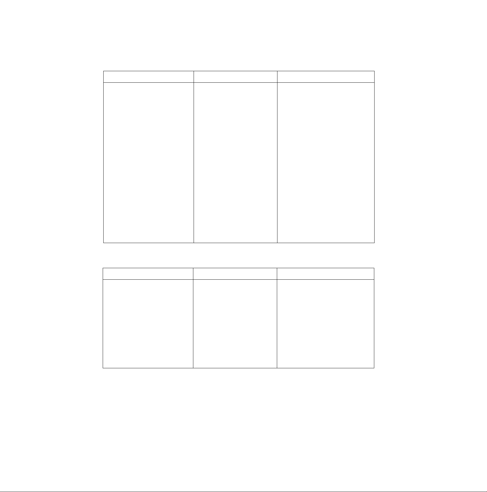
Carriage Control
[i[o©®(jD
Function
Prints, then backspaces one
character
Prints a line, then returns carriage CR
Unidirection mode (single line)
Sets/Releases single direction
printing
Sets/Releases half speed printing ESC “s”
Moves the print position to an
absolute horizontal position
Moves the print position to a relative
horizontal position
Sets absolute vertical print position
Sets relative vertical print position
BS
ESC
ESC
ESC
ESC
ESC
ESC
“U” n
T
r
Name
n=0: Release
n=1: Set
n
ni
n=0: Release
n=1: Set
n=m+n2x256
(0^n,S255)[*c (0^n2^127)cic
ni
r\i n=m +02x256
(0^n,^255)oEc {0^n2S127)oEc
“V”
2 0 Hi Or n=n.+02x256
(0^n,^255)oEc (0Sn2£127)Kc
“v" 2 0 ni 02
n=ni+n2x256
(0^n,S255)oEc (0^n2S127)DEc
Parameter
Data Control
Function
Clears data in line buffer
Selects printer remotely
Deselects printer remotely
Deletes last printable character
Sets MSB on
Sets MSB off
Cancels MSB setting
CAN
DC1
DC3
DEL
ESC “>”
ESC "=”
ESC “#”
Name
Parameter
83
Page 84
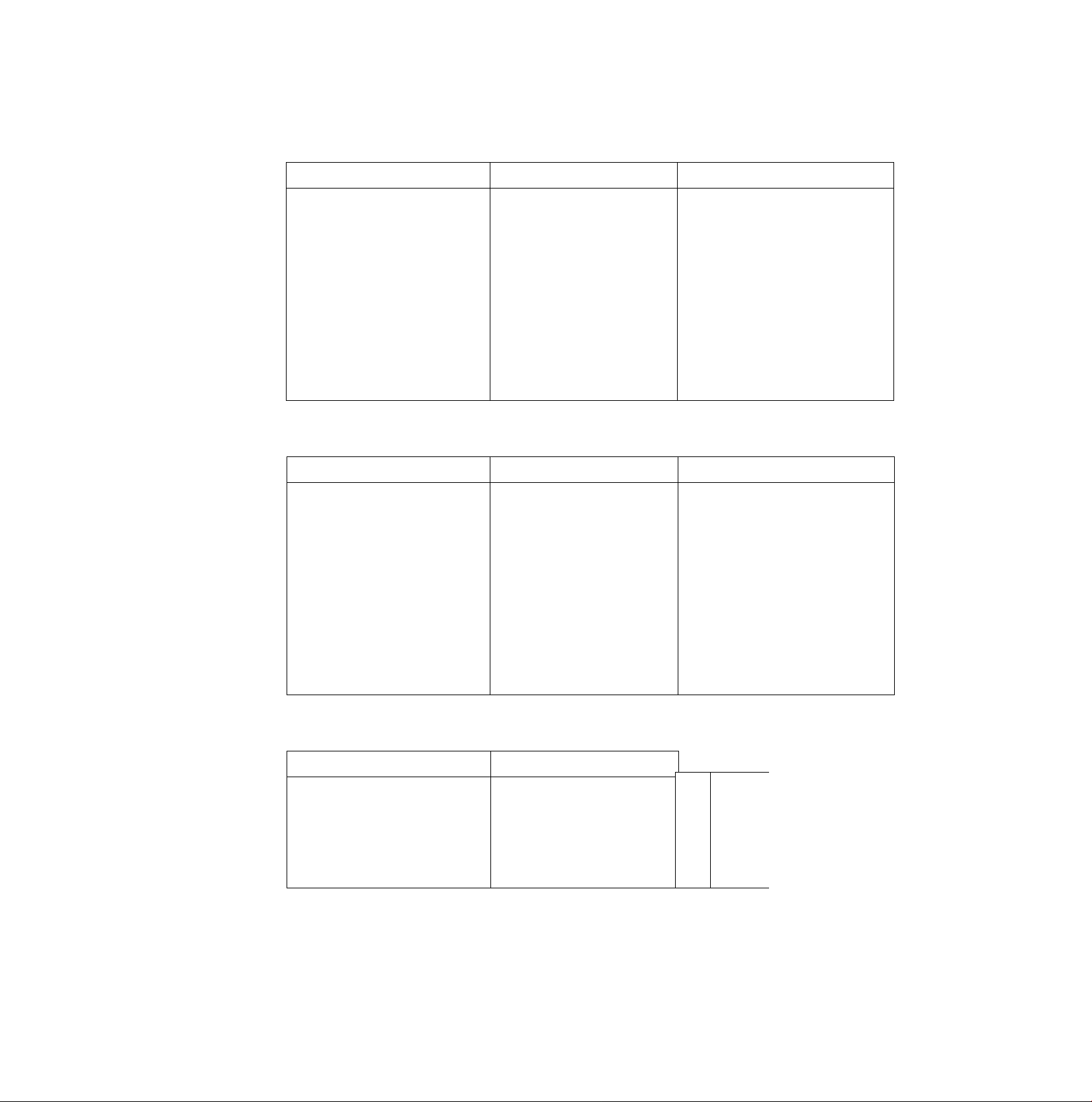
§[ö®2XiD
Download Character Selection
Function
Defines download font
Selects ROM CG
Selects download CG
Copies internal ROM CG font into
download CG
Miscellaneous
Function
Sounds the buzzer
First byte of multi-byte control codes
Last byte of certain multi-byte control
codes
Name Parameter
ESC 0 n m di di di
Data
ESC “%" n n=0: Select ROM Character Generator
n=1: Select download CG
ESC 0 n 0
n=0: Roman
n=1; Sans Serif
n=2; Courier
n=3: Prestige
n=4; Script
n=5; OCR-B
n=6: Bold PS
n=7; Orator
Name Parameter
BEL
ESC
NUL
Initializes the printer
Cut sheet feeder control
Color Selection
Function
Selects print color
ESC
ESC EM n n-“R"; Eject a sheet
n="0”: Cut Sheet Feeder mode
is OFF
n=“4Cut Sheet Feeder mode
is ON
Parameter
Black
Red
Green
ESC “r" n
Name
n=0
n=1
n=2 Blue
n=3 Violet
n=4 Yellow
n=5 Orange
n=6
84
Page 85

This section is for the development of programs and printer drivers and assumes the reader is
proficient in programming. More detailed information has been stored in the Command Reference
program on the Setup Disk, {o^ P. 90)
Font Selection
Function
Selects print quality
Selects print typeface
Selects subscript printing
Selects superscript printing
Releases sub/super script printing
ESC "I” n
ESC “k” n
ESC “S" n
ESC “T”
Name
Parameter
n=0: Internal Draft 10 cpi font
n=2: Internal LQ 10 cpi font
n=3; Internal Proportional LQ font
n=4; Download Draft 10 cpi font
n=6: Download LQ 10 cpi font
n=7: Download Proportional LQ font
n=8: Internal Draft 12 cpi font
n=10: Internal LQ 12 cpi font
n=12: Download Draft 12 cpi font
n=14; Download LQ 12 cpi font
n=16: Internal Draft 17 cpi font
n=18: Internal LQ 17 cpi font
n=20: Download Draft 17 cpi font
n=22: Download LQ 17 cpi cont
n=0: Roman
n=1: Sans Serif
n=2: Courier
n=3: Prestige
n=0: Superscript
n=1: Subscript
n=4: Script
n=5: OCR-B
n=6: Bold PS
n=7: Orator
Character Pitch Selection
Function
Sets elite pitch (12 cpi) printing ESC
Sets compressed (17 cpi) printing SI or ESC SI
Releases elite and compressed
printing
Sets/Releases proportional spacing
DC2
ESC “P” n
Character Highlight Selection
Function
Sets emphasized printing
Releases emphasized printing ESC “F"
Sets double strike printing ESC “G"
Releases double strike printing ESC “H”
Sets single-line double wide printing
ESC “E”
SO or ESC SO
Name
Name
Parameter
n=0: Release n=1: Set
Parameter
(Continued)
85
Page 86

Character Highlight Selection
Function
Releases single-line double wide
printing
Sets/Releases double wide printing
Sets double high & double wide
printing
Sets/Releases underlining
Sets/Releases overlining
Name
DC4
ESC "W” n n=0: Release n=1: Set
ESC “[” 4 0 0 0
mi Line feed
ms m. 0: Unchanged
1: Unchanged
2: Unchanged
16: Single
17: Single
18: Single
32: Double
33: Double
34: Double
m4=0: No change
m4=1: Single-wide
nri4=2: Double-wide
ESC
ESC
n
n
n=0: Release
n=0: Release n=1: Set
Parameter
Character height
Unchanged
Single-line
Double-high
Unchanged
Single-high
Double-high
Unchanged
Single-high
Double-high
n=1: Set
Character Set Selection
Function
Selects alternate character set 1
Selects alternate character set 2
Changes the current code page
ESC “7”
ESC “6”
ESC
nt Hi
Name
Bit Image (Graphics) Mode Selection
Function
Sets 8-pin image standard density (60 dpi)
Sets 8-pin image double density (120 dpi)
Sets 8-pin image double density/double
speed (120 dpi)
ESC K Oi n* Data
ESC "L” ni n* Data
ESC "Y" n, m Data
Name
Parameter
ni=00H and ni=00M: Current
ni=0lH and ni=B5H: USA
n.=03H and ni=52n: Multilingual
ni=03H and nj=5CH: Portugal
ni=03H and ni=5FH: Canada French
ni=03H and ni=6lH: Norway
n.=03H and n2=59M: Turkey
Except the above: Download font
Parameter
86
Sets 8-pin image quadruple density
(240 dpi)
(Continued)
ESC “Z” ni nj Data
Page 87
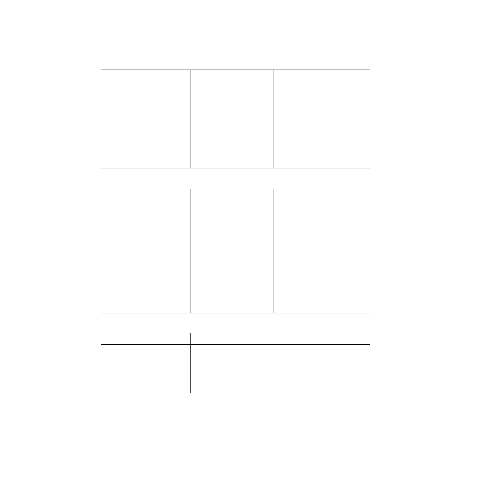
Bit Image (Graphics) Mode Selection
Function
Sets bit image mode selection
Sets bit image mode selection ESC
Paper Feed Selection—
ESC ” m ni m Data 6-pin Dots/Inch
Data m=0: 60 m=8: 60
Amount
Function
Sets paper feed to inch (3.2 mm) ESC “0"
Sets paper feed to 7/^2 inch (2.5 mm)ESC “1”
Executes line spacing set by
ESC “A" n
ESC
Name Parameter
m=0: 60 m=32: 60
m=1: 120 m=33: 120
m=2: 120D
m=3: 240
m=4: 80
m=6: 90
“g" ni ni m
8-pin Dots/Inch
m=1: 120
m=2: 120D
m=3: 240
Name
‘'2’’
24-pin Dots/Inch
m=38: 90
m=39: 180
m=39; 180
24-pin Dots/Inch
m=9: 120
m=11: 180
m=12: 360
Parameter
Sets paper feed to inch ESC
(or rVeo inch in A.G.M. mode)
Sets paper feed to inch ESC "3’’ n {0^n^255)Mc
(or ryiso inch in A.G.M. mode)
Seiects the base line feed unit for ESC
ESC “3’' and ESC “J”
Sets/Reteases automatic line feed
"A” n
T ‘V 4 0 0 0 0
n n=216: 1/^16 inch base unit
ESC "5’’ n n=0; Release
(0Sn^255)D€c
n=180: 1/180 inch base unit
Paper Feed Selection
Function
Feeds paper one line
Feeds paper to next top of form
Executes one-line paper feed of ESC “J” n (0^n^255)DEc
inch
(or f/i80 inch in A.G.M, mode)
LF
FF
Name
n=1: Set
Parameter
87
Page 88
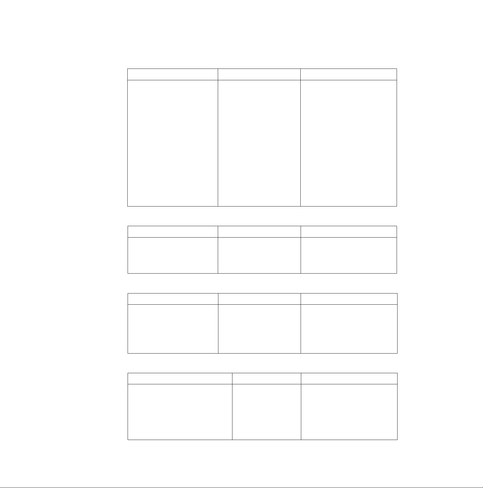
DEGffl
Page Format Selection
Function
Sets page length in inches ESC "C” 0 n (1 ^n^255)oEc
Sets page length in lines ESC "C" n (1gng255)oEc
Sets left and right margins
Sets skip perforation
Reieases skip perforation
Sets top of form
ESC “X" Hi Oi 8" print line
ESC “N" n
ESC “0"
ESC “4”
Name
Pica: 1£niS78 3£ 02^80
Elite: 1^nig93 4Sn2S96
Comp.: 1^01^133 5^02^137
Pica: 1^ni^88 3^02^90
Elite: 1^ni^105 4^02^108
Comp.: 1gn,^151 5^n2g155
(1^n^255)DEc
Tabulation—Horizontal
Function
Sets horizontal tab ESC
Name
“D”
ni m .. n. 0 (1^x^32)
Parameter
9" print line
Parameter
CO
o
fi)
—1
(D
o
o
3
3
0)
3
a
(0
HT
"D”
0
Releases horizontal tab ESC
Executes horizontal tab
Tabulation—Vertical
Function
Sets vertical tab
Releases vertical tab ESC “B” 0
Executes vertical tab VT
Returns to default tabs
ESC “B” ni ni ... n. 0
ESC "R”
Name
(1^x^64)
Parameter
Carriage Control
Function
Prints, then backspaces one character
Prints a line, then returns carriage CR
Sets/Releases single direction printing ESC “U” n n=0: Release n=1: Set
BS
Name
Parameter
88
Moves the print position to a relative
horizontal position (1V120 inch)
ESC “d” ni n* Position: ni+(256xni)
Page 89

Data Control
Function
Clears data in line buffer CAN
Selects printer remotely
Deselects printer remotely
DC1
ESC "0” 36
Download Character Selection
Function
Defines download font
ESC “=” m ns 35 A, Ai
Data
Miscellaneous
Function
Sounds the buzzer
First byte of multi-byte control codes
Last byte of certain multi-byte control
Prints continuously from All
Charalcter chart
BEL
ESC
NUL
ESC “V ni n;
Name
Name
Name
Parameter
Parameter
Parameter
Total count: n2x256-*-ni
Prints one character from All
Character chart
Sets OFF LINE mode
Resets to initial state
Color Selection
Function
Selects print color
ESC
ESC 1"
ESC “K" n, 0 m 36
p. p.
Name
ESC “r” n
Parameter
n=0: Black n=4: Yellow
n=1: Red n=5: Orange
n=2: Blue n=6: Green
n=3: Violet
CO
o
€
fi)
<D
o
o
3
3
o>
3
a
(A
89
Page 90

0 oi o
The Command Reference program allows you to access a detailed explanation of each software
command or the proportional spacing tables on your computer screen. Each displayed explanation
can be printed out if required.
Before you use the Setup Disk, it is recommended that you make a back-up copy and store the
original in a safe place.
Note:
• Use the DISK COPY command of the operating system to make a back-up copy. Refer to your
DOS manual for further information.
•You may find it convenient to install the Setup Disk programs directly onto your C Drive, rather
than reading them from the Setup Disk each time a change is necessary. Either method is
acceptable.
To perform an automatic installation of the Setup Disk files onto your C Drive, refer to page 70.
Insert the back-up disk into either drive A or B.
1
<For DOS>
Type A: (or B:) and
Press [Enter],
Type CMDREF
Press [Enter].
Screen 1 will be displayed.
Screen 1
< < Panasonic KX-P3124 command reference utility (xxxxxxxxxxx) > >
- - SELECT EMULATION - -
LEPSpNj
IBM
<For WINDOWS>
Select Run from the File menu.
Type A:\CMDREF (or B:\CMDREF)
^ Click |OK| (or Press [Enter]).
Screen 1 will be displayed.
90
ttlMi]
[Enter]
IE]
Select emulation
Set emulation
Exit to DOS
Page 91

Press [tD of m.
Select an emulation.
©5M]DDaii)ä
Press [Enter].
The emulation will be set and
screen 2 will be displayed.
Press ( Pg.Up] / [ Pg.Down]
O'’®/®-
Select a command.
Screen 2
< < Panasonic KX-P3124 command reference utility (xxxxxxxxxxx) > >
- - SELECT COMMAND - - (EPSON)
FONT SELECTION
[ESCT’x’+n
ESC+ ’k'+ n
ESC+ ’S’+ 1
ESC+ ’S’+ 0
ESC+ T’
ESC+ ’X’+ m+ ni+ 02
CHARACTER PITCH SELECTION
ESC+ 'P'
ESC+ 'M'
ESC+ 'g'
SI
ESC+ SI
DC2
Select command
Ifig.Upl/ipg .Down]
Enter]
Esc)
I
El
m/[i]
[Pg.Up]/
[Pg.Down]
Go to previous/next category
View command description
SELECT EMULATION mode
Exit to DOS
Move the cursor one line up/down
Moves the cursor to the first command
of the previous/next item
'Selects print quality
'Seleas prinffont style
Selects subscript printing
Selects superscript printing
Releases sub/su|^rscript printing
Selects font by pitch and point
Sets pica pitch (10 cpij printing
Sets elite pitch (12 cpi) printing
Sets micron (15 cpi) printing
Sets compressed (17 cpil printing
Sets compressed (17 cpi) printing
Releases compressed printing
_______________
[Enter]
[Esc]
[E]
Displays the explanation of the command
Returns to screen 1
Exits to DOS
Note:
•There is a list of proportional spacing tables after the software commands list.
If you want to see a porportiona! spacing table, select your desired table and press [ Enter).
91
Page 92

©amnsDixi
Press [Enter],
8
This screen will show the
detailed explanation of the
command.
If you want to exit the
Command Reference
Program, go to step 9.
If you want to print this
explanation, press f Enter]
again and press (Y).
“Y”: The explanation will be
printed.
“N”: The display will return to
screen 3.
Screen 3
< < Panasonic KX-P3124 command relerence utility (xxxxxxxxxxx) > >
[ ESC+’x’+n
TpRllTf'QUAUTYV’
Selects print quality.
Name: ESC
Dec.: 27
Hex.: IB
Comments:
*The following values of n can be used:
n=0: Draft font
n* 1: LQ font
n=2: SLQ mode {Roman 5, 10, 6 and 12 CPI fonts only)
*PANEL LOCK in the Function mode affects this command.
Selects print quality
X
120
78
Text scroll-down/up
Go to previous/next command
SELECT COMMAND mode
Print current command description
Exit to DOS
—^[EPSON]~|
- - END- -
Screen 4
< < Panasonic KX-P3124 command reference utility (xxxxxxxxxxx) > >
[ ESC+_'xV_n __Selects print quality ^^EPSON] j
”plilNT~QUAUfY> * '
Selects print quality.
Name: ESC
Dec.: 27
Hex.: IB
x n
120 n
78 n
Comments:
‘The following values of n can be used:
n* 0: Draft font
n= 1: LQ font
ns: 2: SLQ mode (Roman 5, 10, 6 and 12 CPI fonts only)
Press (E]*
You have exited the
Command Reference
Program.
‘PANEL LOCK in the Function mode affects this command.
Print current command description? (Y / N)
Yes No
Scrolls the text one line down/up
[Pg.Up]/
[Pg.Down]
[Esc]
[Enter]
Displays the explanation of
previous/next command
Returns to screen 2
Prints the detailed explanaion of the
- - END- -
command
[E]
Exits
Note:
•You can proceed through the Command Reference Program using a computer mouse or your
keyboard. Highlight the desired item and click the left mouse button, or follow the directions on
your screen for keyboard operation.
92
Page 93

010
The printer does not require any routine maintenance. However, reasonable care of the printer will
extend its life. The following precautions and periodic measures are recommended:
■Cleaning the unit is the most important operation the user can perform.
The frequency of cleaning is dependent upon the environment.
—Turn the power OFF.
—Clean the case and covers with a soft cloth. Use any mild commercial cleaner on the cloth, do not
spray directly on the printer.
— Remove the top and the smoked plastic covers. Vacuum or dust the inside area of the unit. Be
very careful not to damage the printhead ribbon cable and the carriage drive belt.
—The platen should be cleaned with denatured alcohol only.
—The carriage guide bar can be lubricated with a very light oil. Contact your Authorized Panasonic
Service Center for advice on lubrication.
Ribbon Cassette
A single ribbon permits the printing of approximately 3 million total draft characters. When the printing
starts to fade, gently push the counter spring in the ribbon cassette hole with the tip of a ballpoint pen
or other object. Once the ribbon cassette is mounted onto the carriage and printing is
performed for a short time, the characters will become darker.
Note:
• Do not re-ink the ribbon before printing starts to fade. If the ribbon has too much ink, the
characters may smear when printed.
•Wear and tear of the printhead pins may cause serious damage to the ribbon and cause the
printing to fade. In such cases the printer needs servicing.
5’
(D
3
D)
3
o
<D
93
to
O
c
a
<D
to
3"
o
o
5'
Page 94

olU 0
Most probiems associated with the printer can be traced to improper setup, installation, or cabling.
The error messages shown on the display ((^ Table 6.2) and the following table will assist the user
in identifying and correcting some of the more common problems. If you need additional help, contact
the store from which the unit was purchased.
oio.
Symptom
Ink smears
Printout is faint
Carriage moves but there is
no printing
Printer does not power up
Power is on but printer does
not print
Paper out sensor is
inoperative
Buzzer sounds when installing
single sheet
Possible Cause
Printhead gap lever is not in
the proper position
Printhead gap lever is not in
the proper position
Ribbon not installed correctly Re-insert ribbon
Printhead gap lever is not in
the proper position
No AC power Check power cord
Printer is not ON LINE
Interface cable is not properly
connected
P.O.DETECT is OFF
Paper feed selector is in “[]
PUSH” or “□ PULL” position
Probable Solution
Move the lever toward the {+)
position until ink does not
smear (0^ P. 16)
Set the lever to the proper
position
(Q^ P. 16)
(G^ P. 18-22)
Set the lever to the proper
position
(D^P. 16)
(11^ P. 17)
Press ON LINE switch
Secure connection
p. 17)
Set P.O.DETECT to ON
([®= P. 60, 67)
Set selector to “Q” position
(fl^ P. 16)
u
5*
(D
3
Q>
3
o
(D
Po
o
c
Z
(D
(0
D"
O
O
5'
<o
Paper wrinkles when using
tractor feed
Printer can’t load single sheet
in Friction mode
Unexpected characters
appear in printing
Table 6.1 Troubleshooting (Continued)
No reverse tension on paper
C.S.F. is ON
Paper feed selector is in "[]”
position
Emulation is set incorrectly
Set paper supply lower than
printer
Set C.S.F. to OFF when not
using the Cut Sheet Feeder
(or P. 60, 68)
Set paper feed selector to
position
Check printer driver of your
software package and set
emulation accordingly
(0^ P. 38-40, 58, 63)
94
Page 95

“ÜljiMaiSgODSS^
Symptom
Printout is double-spaced
Keeps printing on the same
line
Wrong character set printed
Cannot change print style
from computer
*KX-PS14 {serial interface
board) is installed but cannot
print
*Cannot use parallel interface
when installing serial
interface board
Possible Cause
AUTO LF is ON Set AUTO LF to OFF
Computer is not sending a LF
command
Wrong character set selected
PANEL LOCK is ON for FONT
and PITCH modes
l/F is set to PARALLEL Set l/F to SERIAL and select
KX-PS14
l/F is set to SERIAL Set l/F to PARALLEL
KX-PS13
Parallel interface cannot be
used when a KX-PS13 is
installed
Probable Solution
{Q^ P. 60, 67)
Set AUTO LF to ON
p. 60, 67)
Set the character set as
required
((^ P. 59, 66)
Set PANEL LOCK to OFF
(Q^ P. 59, 64)
desired parameters
(D^ KX-PS14 manual)
KX-PS14 manual)
Remove KX-PS13 when using
parallel interface
(Q^ KX-PS13 manual)
*Printer does not print in color
*Prints in 2 different colors Yellow color gap lever of color
Table 6.1 Troubleshooting
* Option
Note:
•Your printer has a paper out detector. When an out of paper condition occurs, printing stops,
the printer goes to the OFF LINE mode, and the PAPER OUT light starts blinking. To continue
printing to the end of the current page, follow the steps below.
© Press [ON LINE) repeatedly until the page is completed.
@ Install the new paper.
© Press [ON LINE].
•The paper out detector can be disabled through the Function mode.
Color kit (KX'PCK11) is not
installed
Incorrect emulation is set Select proper printer driver In
kit is not in the proper position
Install the color kit
(KX-PCK11)
your software (Q^ P. 38)
Set color gap lever of color kit
to the proper position
(0^ “Color Adjustment" in the
color kit installation manual)
Reinstall the color kit
(Q^ “Installing the Color Kit”
in the color kit installation
manual)
fio
O
c
<D
CO
3"
o
o
5'
(Q
5*
(D
3
D)
3
o
<D
“I
95
Page 96
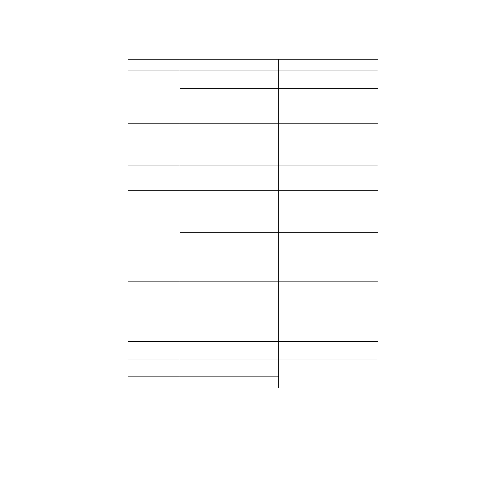
Error Messages
Possible Cause Probable Solution
CANT LOAD
MACRO
CANT PRINT
OUT
CANT SET
MARGIN
PAPER OUT
NO COLOR
RIBBON
NO COLOR KIT
OVERLOAD
Printer can’t load a MACRO in Hex.
Dump mode
Some data remains in printer
Some data remains and printer can’t
output
Margins are set incorrectly
Paper is not installed or is not under
platen
Printer can’t perform color printing
with a black ribbon or without a color
ribbon
Printer can't perform color printing
without a color kit and a color ribbon
Path of printhead is blocked Power off then eliminate
Paper is jamming
Power off then on
Press ON LINE switch to print out
remaining data
With paper installed press ON LINE
switch to print out remaining data
Set margins correctly
{(sr P. 58, 63)
Install paper or load paper by
pressing LOAD/PARK switch
(t^ P. 24-36)
Install a color ribbon
(D^ The color kit installation manual)
Install a color kit and a color ribbon
(D^ The color kit installation manual)
the blockage
Power on to resume printing
Power off then remove the jammed
paper and set paper correctly
Power on to resume printing
Q)
<D
fi)
3
o
(D
o
c
<D
CO
3-
o
o
PRINTHEAD
HOT
NO REV LF/PULL
CANT BACK
PAPER
TOP MARGIN
CANT SET TOF
EEP ROM
ERROR
RAM ERROR
Table 6.2 Error messages
Printhead is overheated and printer
pauses until the printhead
temperature decreases
REV LF/PULL is OFF
Printer can’t back paper past
printable area
Printer can’t back paper past top
margin (only when a top margin is
set)
Printer can't set top of form Check your paper installation
EEP ROM chip is out of order
RAM chip is out of order
Automatic recovery
Set REV LF/PULL to ON
(tl^ P. 60, 68)
Do not back paper past printable
area
Do not back paper past top margin
or reset top margin to 0
((^ P. 24-36)
Contact a local Authorized Service
Center
(O
96
Page 97

Power requirements:
Frequency:
Current:
Interface:
Print fonts:
Software Emulation:
Buffer:
Character sets:
Dot configuration:
Refer to the nameplate located on the rear of the printer.
Centronics parallel
RS-232C/Serial interface board [KX-PS13, KX-PS14] (option)
3 Draft (Pica, Elite, Micron)
8 Letter Quality (Courier, Prestige, Bold PS, Script, Sans Serif, Orator,
Roman, OCR-B)
1 Super Letter Quality (Roman)
6 Scalable fonts (Courier-SC, Bold PS-SC, Prestige-SC, Script-SC,
Sans Serif-SC, Roman-SC)
Epson LQ-570, IBM Proprinter X24E
52K (standard)
96 ASCII characters,
96 Italic ASCII characters,
33 International characters—14 language sets-i-Legal,
33 Italic International characters—14 language sets-i-Legal,
158 IBM-PC special characters—sets 1 &2,
38 Multilingual characters
Vi27 inch (0.2 mm) dot diameter
Draft LQ SLQ
Matrix
(Hor.xVer.) 9x24
Dot pitch
(Hor.) Vl20"
(0.21 mm) (0.07 mm) (0.07 mm)
(Ver.) 1/180"
(0.14 mm) (0.14 mm)
30x24
1/360"
1/180" 1/360"
30x48
1/360"
(0.07 mm)
Maximum number
of characters per
line (cpI):
Print line (879")
Printing speed
[characters per
second (cps)]: LQ 106 cps
with black
(Continued)
Print line
Pica [10 characters per inch (cpi)] 80 / 90 cpi
Elite (12 cpi) 96 / 108 cpi
Micron (15 cpi) 120/ 136 cpi
Compressed (17 cpi)
Elite compressed (20 cpi)
Pica elongated (5 cpi)
Elite elongated (6 cpi) 48/ 54 cpi
Micron elongated (7.5 cpi)
Compressed elongated (8.5 cpi)
Elite compressed elongated (10 cpi) 80 / 90 cpi
Draft 320 cps
SLQ
8" / 9"
137/ 155 cpi
160/ 181 cpi
40 / 45 cpi
60/ 68 cpi
68/ 77 cpi
Micron Elite Pica
256 cps 213 cps
85 cps
42 cps
71 cps
35 cps
97
Page 98
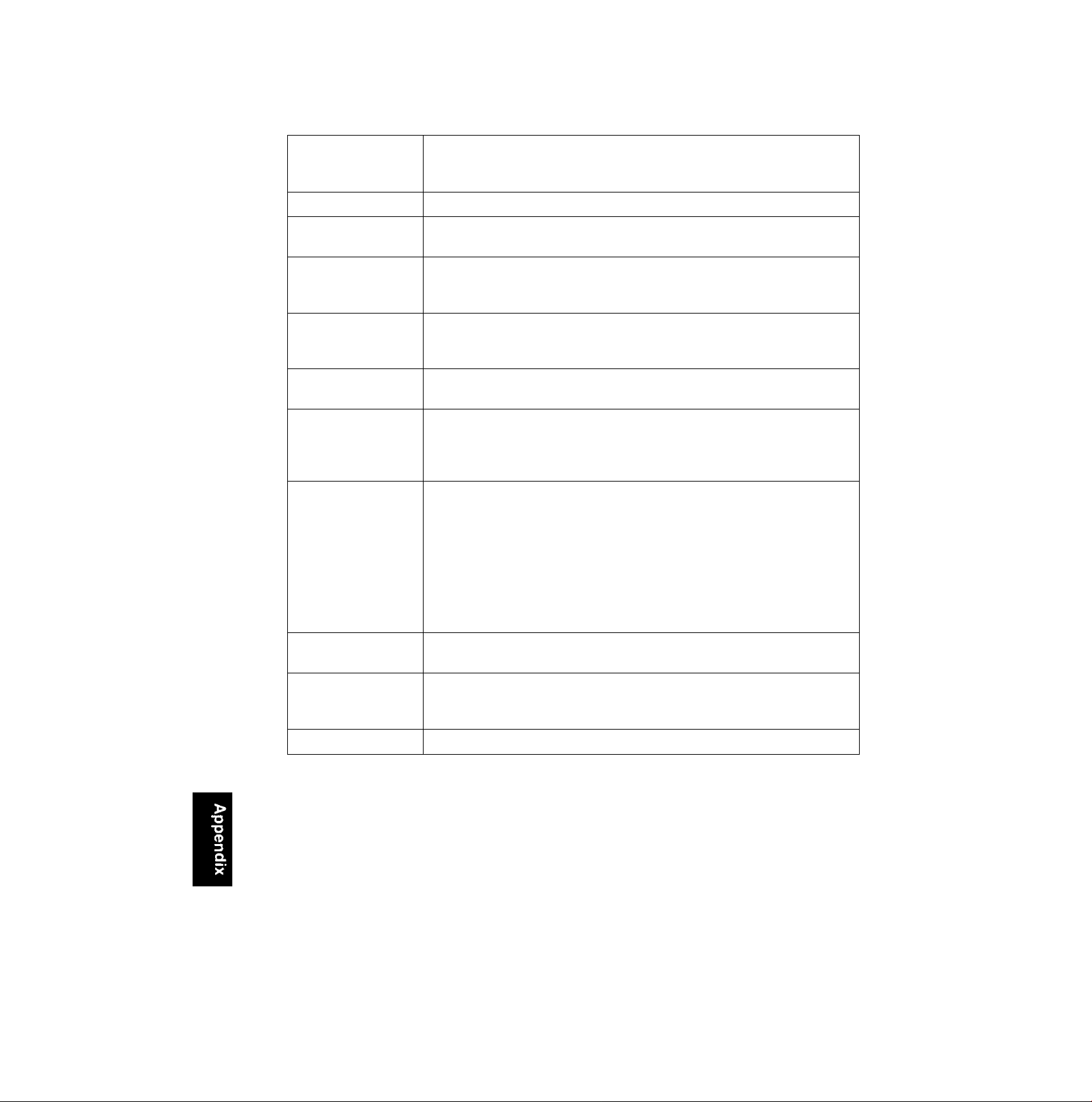
Printing direction:
Line feed time: Approx. 90 msec [with i/fe inch (4.2 mm) line feeding] 2.5 ips at Form Feed
Paper feed: Push/Pull (user selectable) Tractor feed (with fanfold paper)
Bi-directional Character & Graphics
Uni-directional Character & Graphics:
Color Printing
Friction feed (with single sheet or envelopes)
Operating
environment:
Power consumption: MAX—250 W
Storage
environment:
Head service life;
Ribbon:
Dimensions:
Temperature: 10°C to 35°C (50“F to 95T}
Humidity: 30 to 80% RH (Please allow the printer to stabilize at room
temperature within the operating temperature range before operation)
Stand by—12 W
Self Test—50 W
Temperature: -20“C to 60”C (-4°F to 140“F}
Humidity: 10 to 90% RH
Black ribbon;
Approx. 200 million strokes in draft mode
Color ribbon:
Approx. 100 million strokes in draft mode
Cassette seamless fabric ribbon
Black ribbon cassette KX-P150:
Life expectancy (in Draft mode) (rolling ASCII)
Approx. 3 million characters
Color ribbon cassette KX-P150C (option):
Life expectancy (in Draft mode) (rolling ASCII)
Black: Approx. 0.7 million characters
Red (Magenta)/Blue (Cyan): Approx. 0.7 million characters
Yellow: Approx. 0.4 million characters
484 (W)x391 (D)x160 (H) mm
{19.0"x15.4"x6.3"}
98
Detectors Paper out detector
Overheat detector
Overload detector
Mass {Weight}:
Approx. 8.5 kg (18.7 lbs.)
Page 99

Paper which may be used with this unit must be within the specifications provided below.
Fanfold Paper
Width: 4 to 10 inches (102 to 254 mm)
Quality and number of sheets:
Weight
Type of paper
Fine-quality paper
Non-carbon
Multi-layered with carbon
^only for the last sheet
Note:
•When using multi-part fanfold paper, especially in environments which have very high or low
temperature and/or humidity, we recommend the use of the bottom feed pull mode to optimize
paper handling and print quality.
•To insure optimum print quality, 16 to 22 lbs (60 to 83 g/m^) is recommended for graphic
printing.
• In multi-layered paper with carbon, the carbon is equivalent to a sheet of paper.
•“Weight in pounds" represents the weight of 500 [17x22 inches (432x559 mm)] sheets.
•The printer will handle multipart papers up to 0.013 inch (0.32 mm) thick. Up to 4 copies of
14 lb. chemical release paper can be used.
• Multipart forms consisting of 2 parts may be used for rear feeding (Push mode). For 3 or 4 part
forms, we recommend bottom feeding for optimum print quality.
Sheets
push pull push pull
1
2 to 4 11 to 14 (17*) 41 to 53 (64*)
2
16 to 22 16 to 24 60 to 83 60 to 90
lbs
11 to 14 (17*) 41 to 53 (64*)
g/m^
Single Sheet
Width: 4 to 11.7 inches (102 to 297 mm)
Height: 5 to 14.3 inches (127 to 363 mm)
Weight in pounds (g/m^): 14 to 24 (53 to 90 g/m^)
Envelope
#6 and #10 size envelopes are recommended. Since envelopes vary in size, paper weight and
construction, we cannot guarantee print quality and paper handling for all types of envelopes.
Note;
•To optimize print quality printing should not occur in areas where the edges overlap.
99
Page 100

^[pecsflOOsgiM?^
Printing Area
Fanfold paper
o
o
o
o
1st character
o
o
o
Printing area
o
o
o
-Q ~
Paper perforations
o
A 1" (25.4 mm)
B
C
D
Push Pull
0.7" (17.8 mm)
0.6" (15.2 mm)
1" (25.4 mm)
5.4" (137 mm)
o
o
o
o
o
Printing area
o
o
■e-
o
A: Value A indicates the area near the paper perforations
where the quality may not be optimum.
B; Value B indicates the minimum distance between the
sprockets and first printable character. {When the left tractor
is set on the left end and the margin is set to 0.)
C: Value C indicates the area from the top edge of the paper to
the top of the first printed character.
D: Value D indicates the position where paper out is detected
and printing may not be optimum.
Single sheet and Envelope
1 St character
Printing area
Single Sheets and Envelopes
B
1.5" (38 mm)
c 0.6" (15.2 mm)
D 1"(25.4 mm)
B: Value B indicates the minimum distance between the
edge of the paper and the first printable character. (When
the left paper guide is set to the left end and the margin is
set to 0.)
C: Value C indicates the area from the top edge of the paper
to the top of the first printed character.
D: Value D indicates the position where paper out is detected
and printing may not be optimum. (When printing on enve
lopes do not print on area where edges overlap. Print
quality may not be optimum.)
100
 Loading...