

Page 1

Panasonic
Operating Instructions
Impact Dot Matrix Printer
KX-P3123
Quiet
Before operating this unit, please read these instructionscompietely.
C tUiftftMi CUdnc KIrtWii Co Lti
AM rntrvts uoeiOieoad
copy«9 iN etinNten s • vioMKfn of iiw
Page 2

FOR USER IN THE UNITED STATES ONLY
This equipment has been tested and found to comply with the limits for a Class B digital
device, pursuant to Part 15 of FCC Rules. These limits are designed to provide
reasonable protection against harmful interference in a residential installation. This
equipment generates, uses and can radiate radio frequency energy and, if not installed
and used in accordance with the instructions, may cause harmful interference to radio
communications. However, there is no guarantee that interference will not occur in a
particular installation. If this equipment does cause harmful interference to radio or
television reception, which can be determined by turning the equipment off and on, the
user is encouraged to try to correct the interference by one or more of the following
measures:
® Reorient or relocate the receiving antenna.
® Increase the separation between the equipment and receiver.
° Connect the equipment into an outlet on a circuit different from that to which the receiver
is connected.
® Consult the dealer or an experienced radio/TV technician for help.
The user may find the booklet "Something About Interference" available from FCC local
regional offices helpful.
FCC Warning: To assure continued FCC emission limit compliance, the user must use
only the recommended shield interfacing cable when connecting to a host computer. Also,
any unauthorized changes or modifications to this equipment would void the users
authority to operate this device.
All Rights Reserved. © COPYRIGHT 1993 KYUSHU MATSUSHITA ELECTRIC CO., LTD.
Page 3

WARNING
® The power source voltage of this unit is listed on the nameplate. Plug the printer only
into an outlet with the proper voltage.
* To prevent fire or shock hazard, do not expose this product to rain or any type of
moisture.
® When you operate this equipment, the outlet should be near the equipment and should
be easily accessible.
The serial number of the unit may be found on the label on the rear of the unit. For your
convenience, note this number below, and retain this book, along with your proof of
purchase, to serve as a permanent record of your purchase in the event of a theft, or for
future reference.
MODEL NO.
SERIAL NO.
KX-P3123
NAME OF DEALER
DATE OF PURCHASE
IBM and IBM-PC are registered trademarks of International Business Machines
Corporation.
Proprinter is a trademark of International Business Machines Corporation.
Windows is a trademark of Microsoft Corporation.
Epson is a registered trademark of Seiko Epson Corporation.
Epson ESC/P2 is a trademark of Seiko Epson Corporation.
Adobe, ATM and the ATM logo are trademarks of Adobe Systems Inc., which may be
registered in certain jurisdictions.
Any details given in these operating instructions are subject to change without notice.
Page 4

Table of Contents
Introduction
Features ................................................................. 7
Chap. 1
Chap. 2
Before You Start
Cautions
Operating Environment...................................................... 8
Precautions........................................................................ 9
Unpacking
Assembling the Parts
Parts of the Printer.............................................. 12
.................................................................
............................................................
.....................................................
8
10
11
Setup
Connecting to a Computer
Ribbon Cassette.................................................. 15
Installing the Ribbon Cassette ........................................ 15
Removing the Ribbon Cassette ...................................... 18
Paper Feed Selection.......................................... 20
Installing Paper
Fanfold Paper (Push Tractor Mode/Rear Feeding)
Fanfold Paper (Pull Tractor Mode/Bottom Feeding) .... 25
Single Sheets and Envelopes (Friction Mode)
Characters Alignment...................................................... 31
..................................................
.................................
.......
...............
14
21
21
29
Chap. 3
Printer-Driver Selection
Installing a Printer-Driver (Windows Ver. 3.1)
......................................
.........
32
33
Self Test ............................................................... 35
Using the Printer
SUPER QUIET Mode ........................................... 36
Feeding Paper ..................................................... 37
(Form Feed/Line Feed/Micro Line Feed/
Reverse Micro Line Feed)
Tear Off (Rear Feeding Only)
Paper Parking (Rear Feeding Only)
Setting the Top of Form (TOF) ....................................... 41
.............................................
..........................................
...............................
37
37
39
Page 5

Table of Contents
Setting the Control Table.................................... 43
Printing Out the Current Settings in MACROS
Setting the FONT/PITCH/FORM LENGTH
Setting the LEFT/RIGHT MARGIN ................................. 46
Defining MACRO (MACRO Save) .................................. 48
Recalling a Defined MACRO (MACRO Recall)
Recalling FACTORY Settings (Default Settings)
Setting a COLOR ............................................................ 53
...............
.....................
..............
............
43
44
50
51
Chap. 4
Chap. 5
Initial Setup Mode
________________
Using the Control Panel...................................... 55
Printing Out the Current Settings
Setting the Initial Setup Mode.......................................... 59
Resetting to FACTORY Settings
Using the Setup Disk
Running the Initial Setup Program
Printing Settings
Setting Selections on Setup Disk
Save to Disk..................................................................... 68
Load from Disk................................................................ 69,
Send to Printer................................................................. 69
Resetting to FACTORY Settings
Help................................................................................. 71
..............................................................
..........................................
....................................
...................................
.................................
....................................
...................................
58
61
62
65
66
66
71
Software Commands
Epson ESC/P2™ Mode (Epson LQ-570 Mode)
.........
73
Chap. 6
IBM Proprinter X24E Mode
.................................
Command Reference Program
(Using the Setup Disk)
...................................................
iVlaintenance & TroubOeshooting
Periodic Maintenance
Troubleshooting
..................................................
.........................................
79
84
87
88
Page 6

TabBe of Contents
Appendix
Printer Specifications
........................................
90
Paper Specifications........................................... 92
Fanfold Paper.................................................................. 92
Single Sheets
Envelopes........................................................................ 92
Printing Area.................................................................... 93
Interfacing
Parallel Interfacing........................................................... 94
.................................................................
............................................................
92
94
Initialization ......................................................... 97
Hex Dump............................................................. 98
Character Set Tables........................................... 99
Glossary
..............................................................
105
Index.......................................................................Ill
Options and Supplies
.......................................
114
Page 7

Congratulations on purchasing a Panasonic printer.
This printer is a versatile, high quality 24-pin dot matrix printer which is designed to meet the needs
of your office.
This printer has been factory set to operate with most of the popular software packages.
Your application software should control the printer functions. In most cases, there will be no need to
change the initial printer settings.
Printer Emulation:
Setup Disk:
ATM Disk:
Super Quiet Mode:
Color Printing:
Fonts:
Printing Speed:
Paper Handling:
Paper Paths:
Epson LQ-570 and IBM Proprinter X24E
A printer-driver for Windows Ver. 3.1, initial setup
program and command reference program
Adobe Type Manager with 13 scalable Adobe fonts for
Windows Ver. 3.0 or higher
Reduces printing noise
7 colors with the optional color kit (KX-PCK11)
3 Draft ( Pica i Elite . ^licron )
6 Letter Quality ( courier , bom ps, prestige , scM^jixt >
Sans Serif , Roman )
1 Super Letter Quality ( Roman )
4 Scalable fonts ( Roman , Sans Serif, Courier .Prestige )
Draft — 192 characters per second (12 cpi)
LQ — 64 characters per second (12 cpi)
SLQ — 32 characters per second (12 cpi)
Friction and Tractor (Pull and Push)
Rear, Bottom, Top
Tear Off:
Paper Parking:
Cut Sheet Feeder Option
(KX-PT10):
Serial Interface Option
(KX-PS13 and KX-PS14):
Advances fanfold paper’s perforation to tear position
Allows single sheets/envelopes to be used without
removing/wasting fanfold paper
Provides fast and automatic feeding of single sheets
You may select parallel or serial when either serial
interface board is installed
Page 8
i ■ ' if iij ! li',
I;. " t ». 11-I
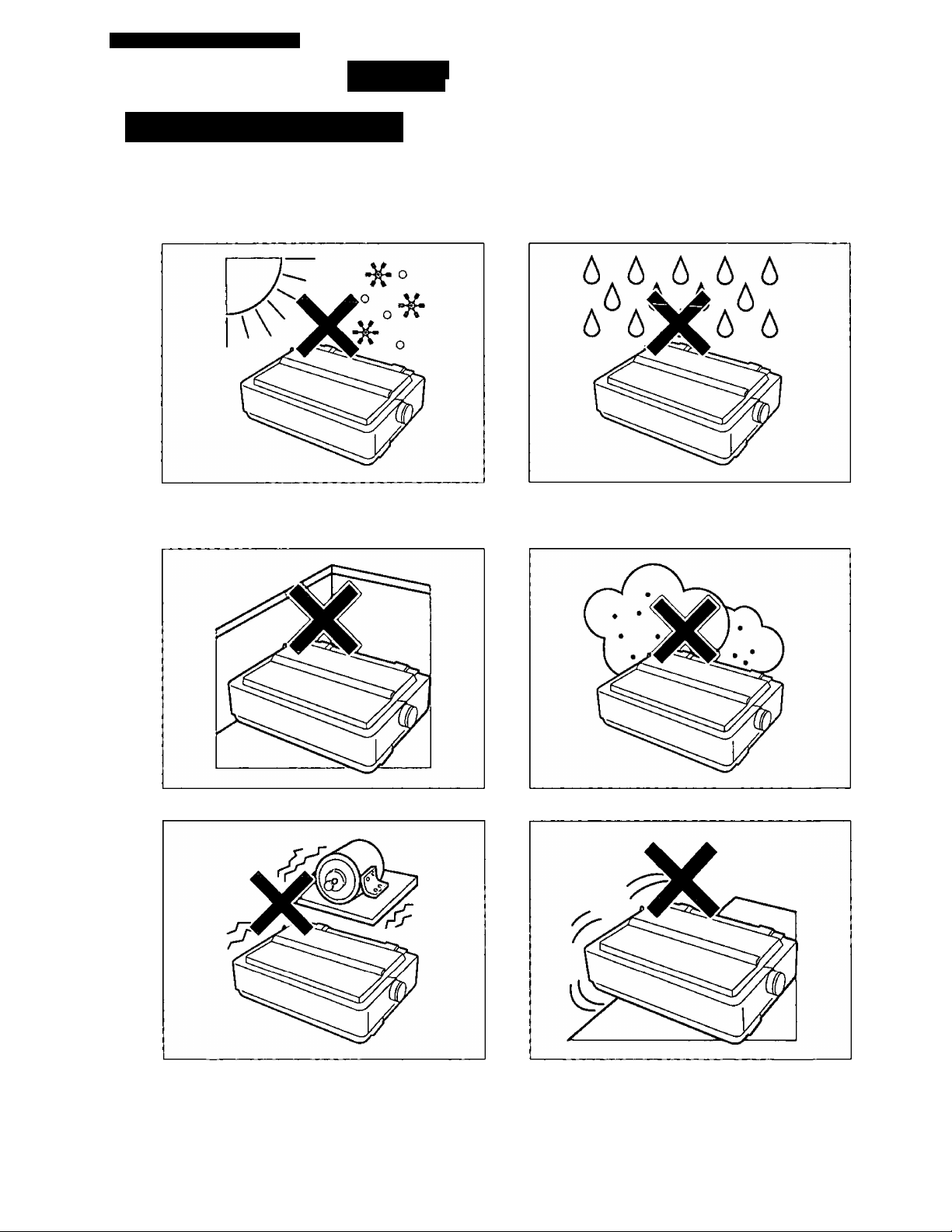
Operating Environment
Do not use the printer under the following conditions.
CO
D)
Extremely high or low temperature
[temperature range: 10-35'C {50~95T)]
Areas of poor ventilation
[a minimum of 4" (10 cm) clearance on all
sides is necessary to insure proper ventilation]
Extremely high or low humidity
(humidity range: 30-80% RH)
Areas of high dust concentration
8
Areas with extreme vibration
Areas on an unstable or unlevel surface
Page 9
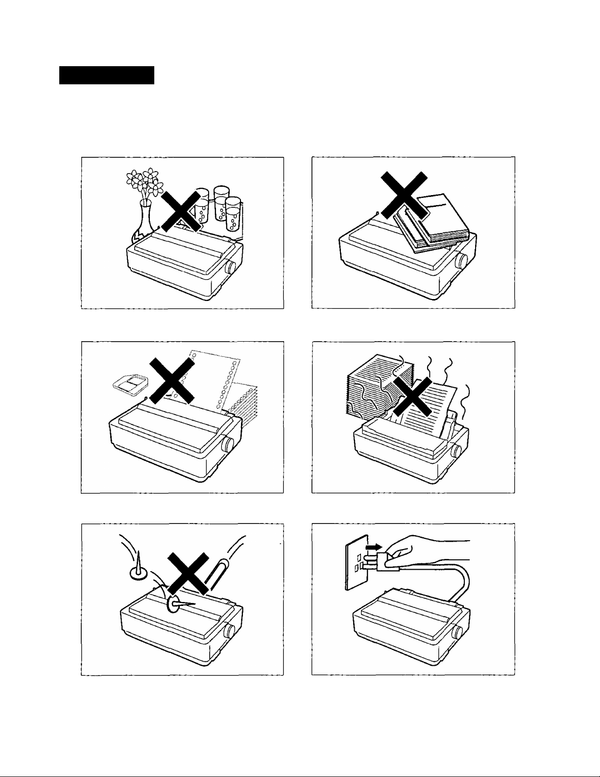
Precautions
The following precautions are recommended to extend the life of the printer.
Keep all liquids away from the printer.
— Accidental spillage of a liquid into the printer
can cause severe damage.
Do not place books, paper, or other items
on top of the printer.
Do not operate the printer without paper
and a ribbon cassette installed.
Do not obstruct the movement of the
printhead while in operation.
Avoid prolonged use without allowing the
printhead time to cool.
If the printer is not going to be used for an
extended period, unplug the power cord.
Page 10
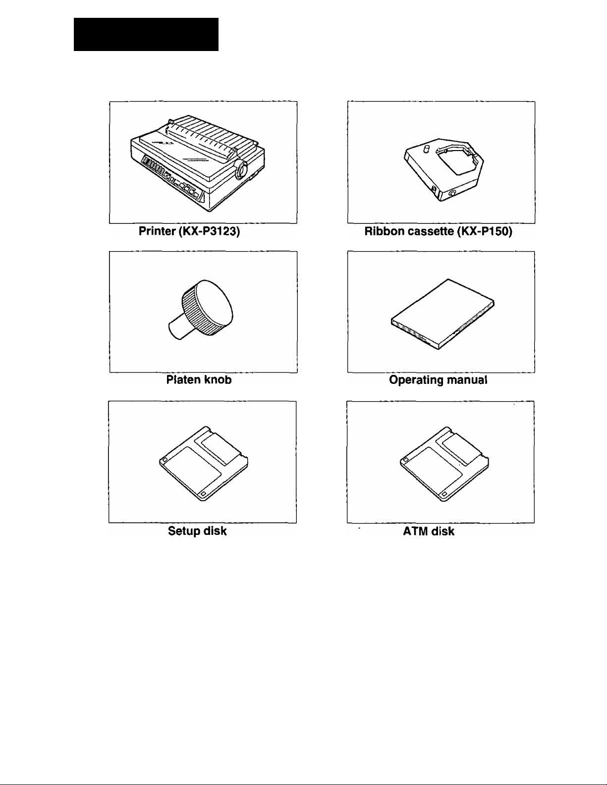
Unpacking
Having unpacked the printer, make sure none of the contents shown below are missing or damaged.
Report damages or shortages to the store from which the unit was purchased.
10
This setup disk contains a printer-driver
for Windows Ver. 3.1 (P. 33), an
initial setup program (i®’ P. 55) and a
command reference program
P.84).
To use this setup disk you need to have
an IBM-PC or a compatible computer
with a 3.5'" floppy disk drive.
Note:
• It is recommended that you save the original carton and packing materials for proper shipping
and transporting of the printer.
• For detailed information on ATM
disk, refer to ATM disk manual.
Page 11
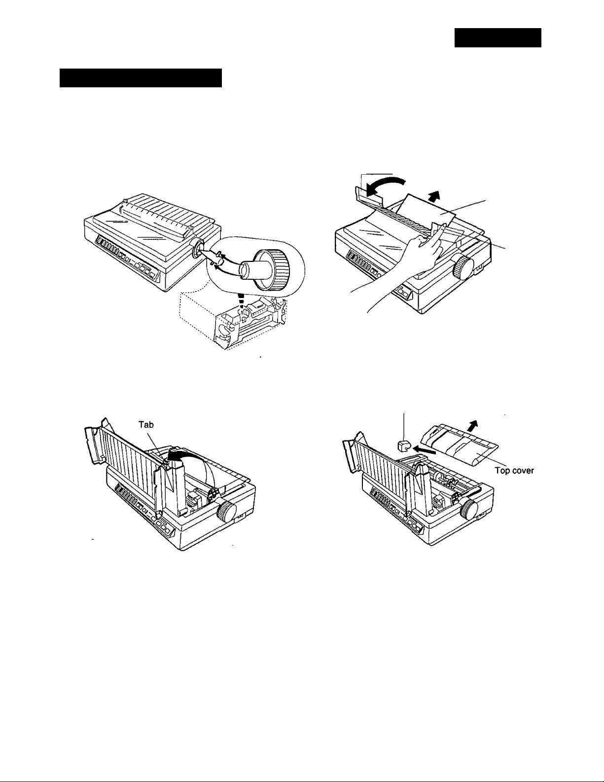
Assembling the Parts
Unpacking
O Insert the platen knob into the hole
on the right side of the printer and rotate it
slowly until it slips onto the shaft. Push the
platen knob onto the platen shaft to secure.
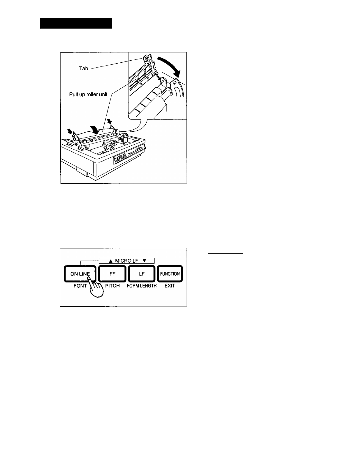
® Open the smoked plastic cover.
@ Fold the smoked plastic cover
forward, and remove the protective
paper.
Smoked plastic cover
O Remove the top cover pad.
Protective
paper
Tab
U)
o
o
(D
-<
O
c
0)
Q)
3.
Top cover pad
11
Page 12
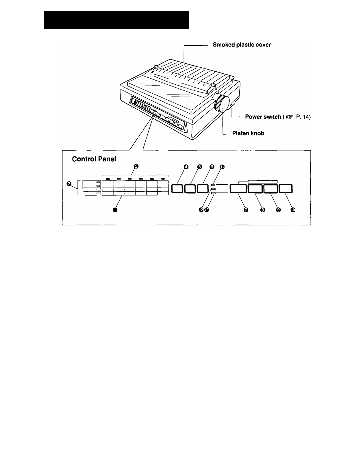
Parts of the Printer
® Control table
This control table shows the details of the
setting for each item.
® Row indicators
This indicates the selected item.
@ Column indicators
This indicates the elements of each item.
@ SUPER QUIET (TOF) switch
Pressing this switch reduces print noise,
however, it also reduces the printing speed.
Pressing this switch alternately turns the
SUPER QUIET mode on/off. P. 36)
In the FUNCTION mode, pressing this
switch sets the Top of Form (TOF).
(C5* P. 41)
® TEAR OFF (OTHERS) switch
Pressing this switch will advance or reverse
the paper for tearing off in the OFF LINE
mode, or when not printing in the ON LINE
mode, (ns* P. 37)
In the FUNCTION mode, pressing this
switch wiil advance the column position
for the OTHERS on the controi table.
© LOAD/PARK (SET) switch
Pressing this switch will load/park the paper
in the OFF LINE mode, or when not printing
in the ON LINE mode. (>®’ P. 39)
In the FUNCTION mode, pressing this
switch will set or release the items on the
control table.
@ ON LINE (FONT) switch
This switch opens and closes the
communication lines with the computer.
In the FUNCtiON mode, pressing this
switch advances the column position for
the FONT on the control table.
® FF (PITCH) switch
Pressing this switch advances the paper to
the top of form on next page in the OFF LINE
mode or when the printer is not printing in the
ON LINE mode (depending on your TOF
setting).
In the FUNCTION mode, pressing this
switch advances the coiumn position for
the PITCH on the control table.
12
Page 13
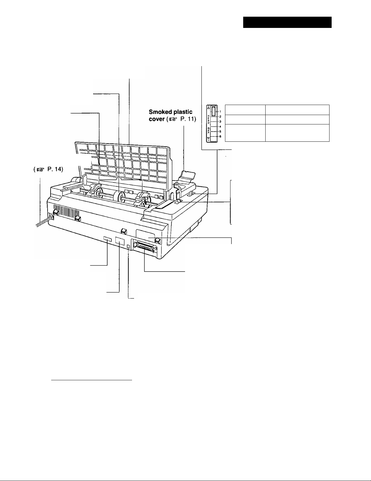
(Rear View)
Parts of the Printer
Paper support
(c^ P.22)
Tractors
( P. 22)
AC power cord \\
Top cover
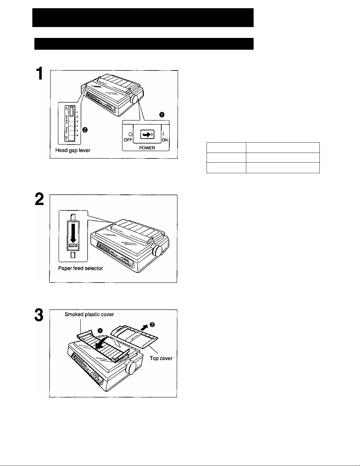
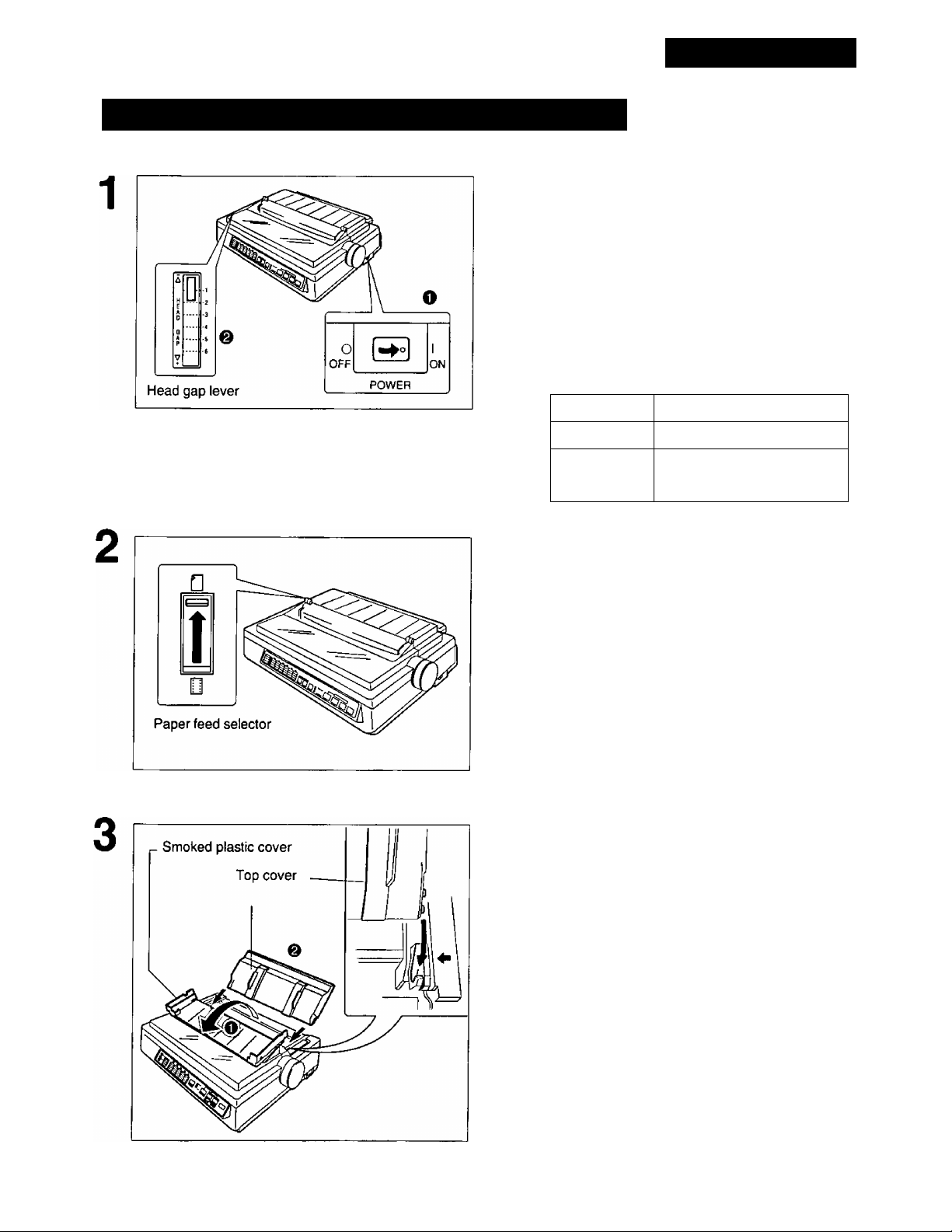
Head Gap Lever
Adjusts the gap between the platen and the
printhead. The lever moves in increments of
0.0028 inch {0.07 mm).
Position Used for
1 or 2 Thinner sheets
3, 4, 5 and 6 Thick or multiple
sheets, envelopes
Paper Feed Selector
“ Q ” (Friction) Single sheets
and envelopes
“ |]]” (Tractor) Fanfold paper
Serial No. Label
Nameplate
Frame ground
terminal ( d®“ P. 14)
LF (FORM LENGTH) switch
Pressing this switch advances the paper one
tine at a time. Holding this switch wilt
advance the paper continuously until the
switch is released. These functions are
active in the OFF LINE mode or when not
printing in the ON LINE mode.
In the FUNCTION mode, pressing the
switch advances the column for the
FORM LENGTH on the control table.
_________
FUNCTION switch
This switch allows you to enter and exit the
FUNCTION mode.
Serial interface cover
Centronics parallel interface
connector (us* P. 14, 94)
(Q) ON LINE/FUNCTION indicator
This indicator is lit when the printer is in the
ON LINE mode, and is out in the OFF LINE
mode. It blinks in the FUNCTION mode.
@ SUPER QUIET indicator
This indicator is lit when the printer is in the
SUPER QUIET mode.
@ POWER/PAPER OUT indicator
This indicator is lit when the power is on and
paper is installed. It blinks when paper is not
installed.
13
Page 14
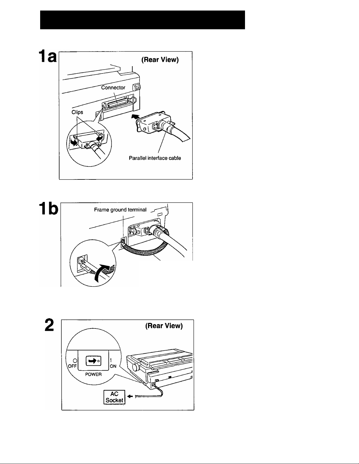
Connecting to a Computer
Attach one end of the parallel interface
cable to your printer as shown, and
the other end to your computer.
Be sure to secure the printer clips.
r Note:
• If you do not have a parallel interface
I from your local computer store or dealer.
cable, you v^ill need to purchase one
Frame ground wire
If the cable has a frame ground wire,
connect it to the frame ground
terminal.
Plug the printer into a grounded 3
prong AC socket.
When power is supplied to the printer, the
power indicator on the control panel will
light.
14
Page 15
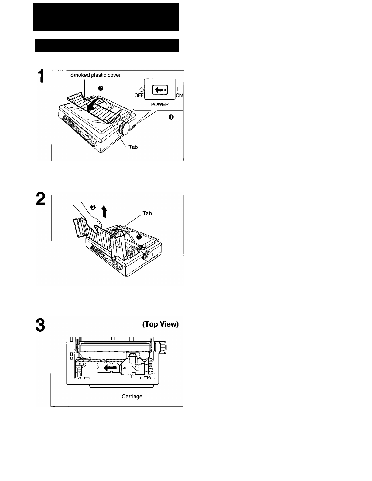
Rlbbfti Cassette
Installing the Ribbon Cassette
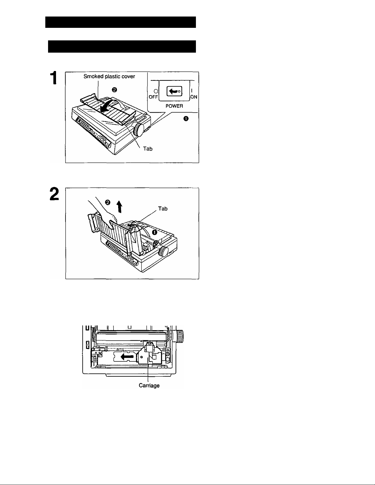
O Turn the power switch off for
safety.
@ Fold the smoked plastic cover
forward by lifting tab on right side.
O Raise the smoked plastic cover.
O Remove the smoked plastic cover.
Caution:
• The printhead may be hot. Use caution
when the cover is open.
Gently slide the carriage toward the
center of the unit.
15
Page 16
Ribbon Cassette
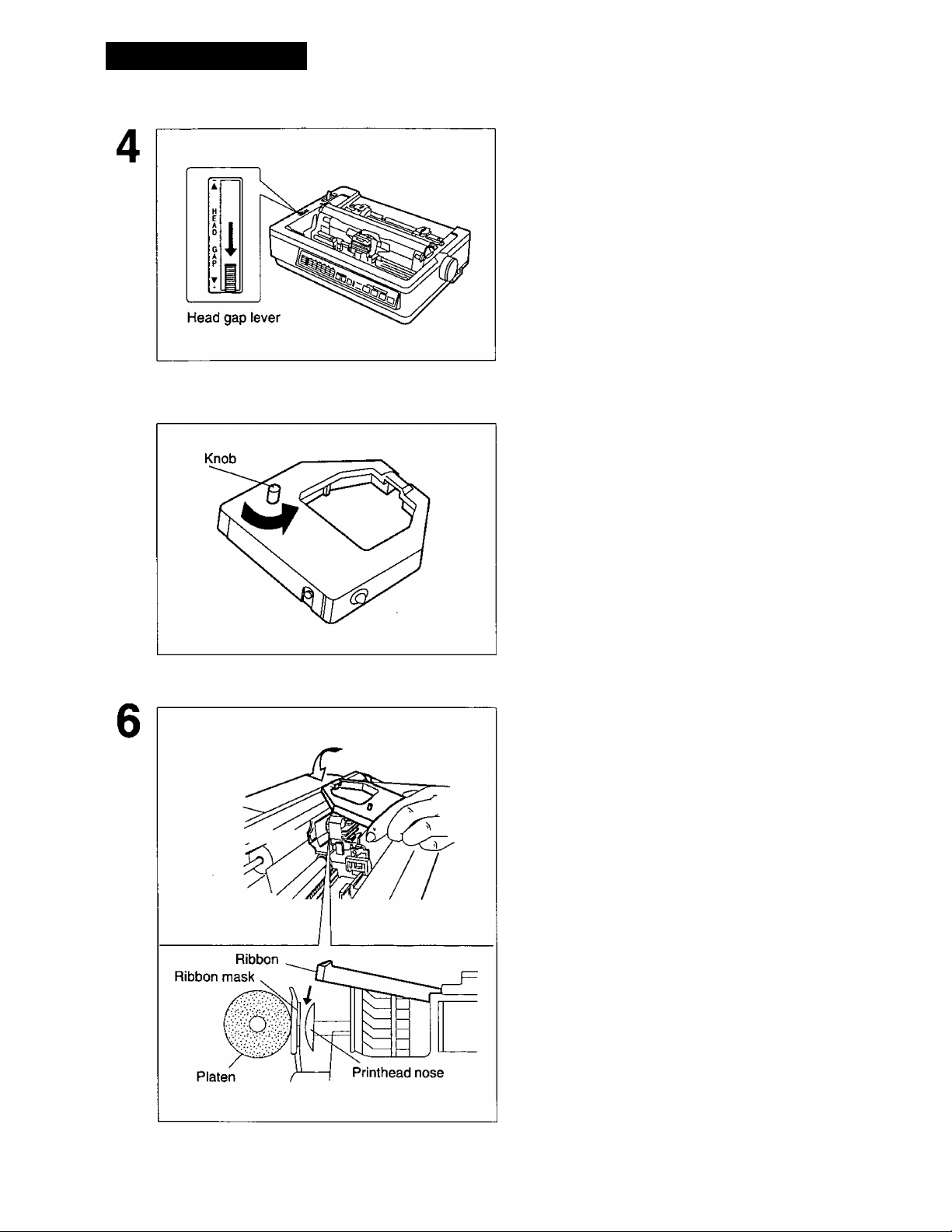
Move the head gap lever to the (+)
position.
Rotate the knob on the ribbon
cassette to remove any slack.
Slip the ribbon between the ribbon
mask and the printhead nose.
16
Page 17
Replace the smoked plastic cover to
8
its original position.
Ribbon Cassette
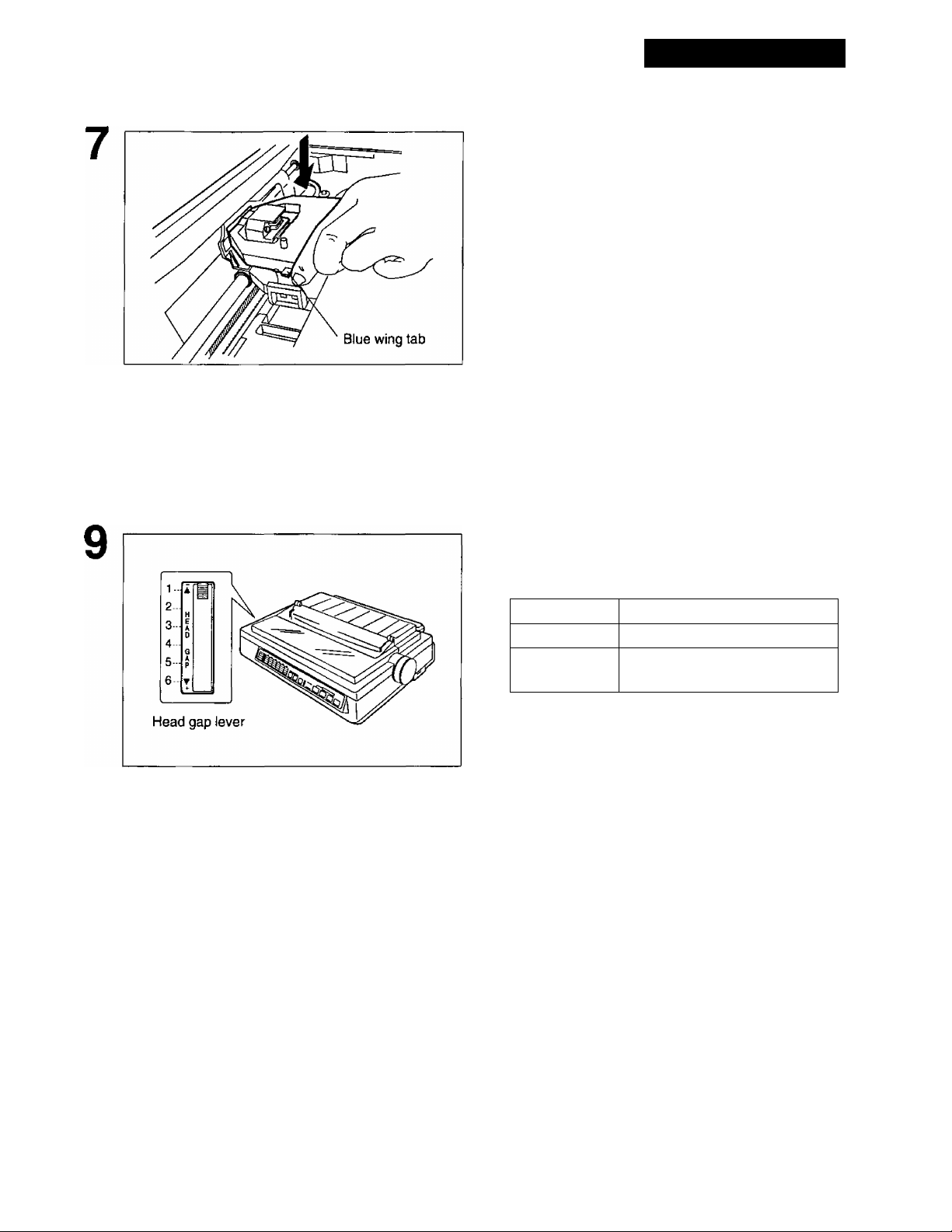
Press down on rear of the cassette
until the blue wing tab snaps into
place.
Adjust the head gap lever for the thick
ness of the paper you are using.
Position
1 or 2 Thinner sheets
3, 4, 5 and 6 Thick or multiple sheets or
envelopes
Use for
17
Page 18
Ribbon Cassette
Removing the Ribbon Cassette
O Turn the power switch off for
safety.
@ Fold the smoked plastic cover
forward by lifting tab on right side.
O Raise the smoked plastic cover.
(Top View)
O Remove the smoked plastic cover.
Caution:
• The printhead may be hot. Use caution
when the cover is open.
Gently slide the carriage toward the
center of the unit.
18
Page 19
Ribbon Cassette
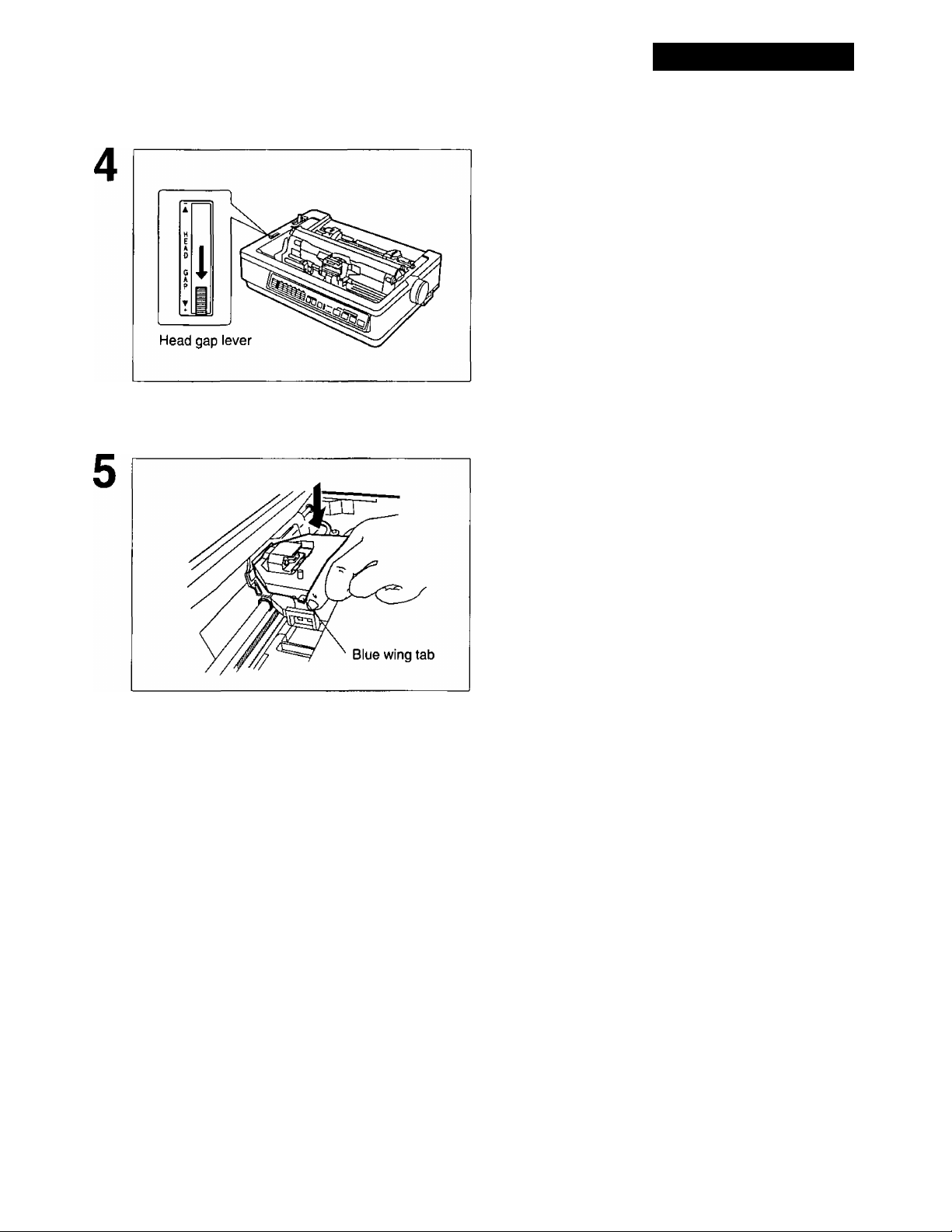
Move the head gap lever to the (+)
position.
Spread the blue wing tab and lift upthe
cassette.
19
Page 20
Paper Feed Selection
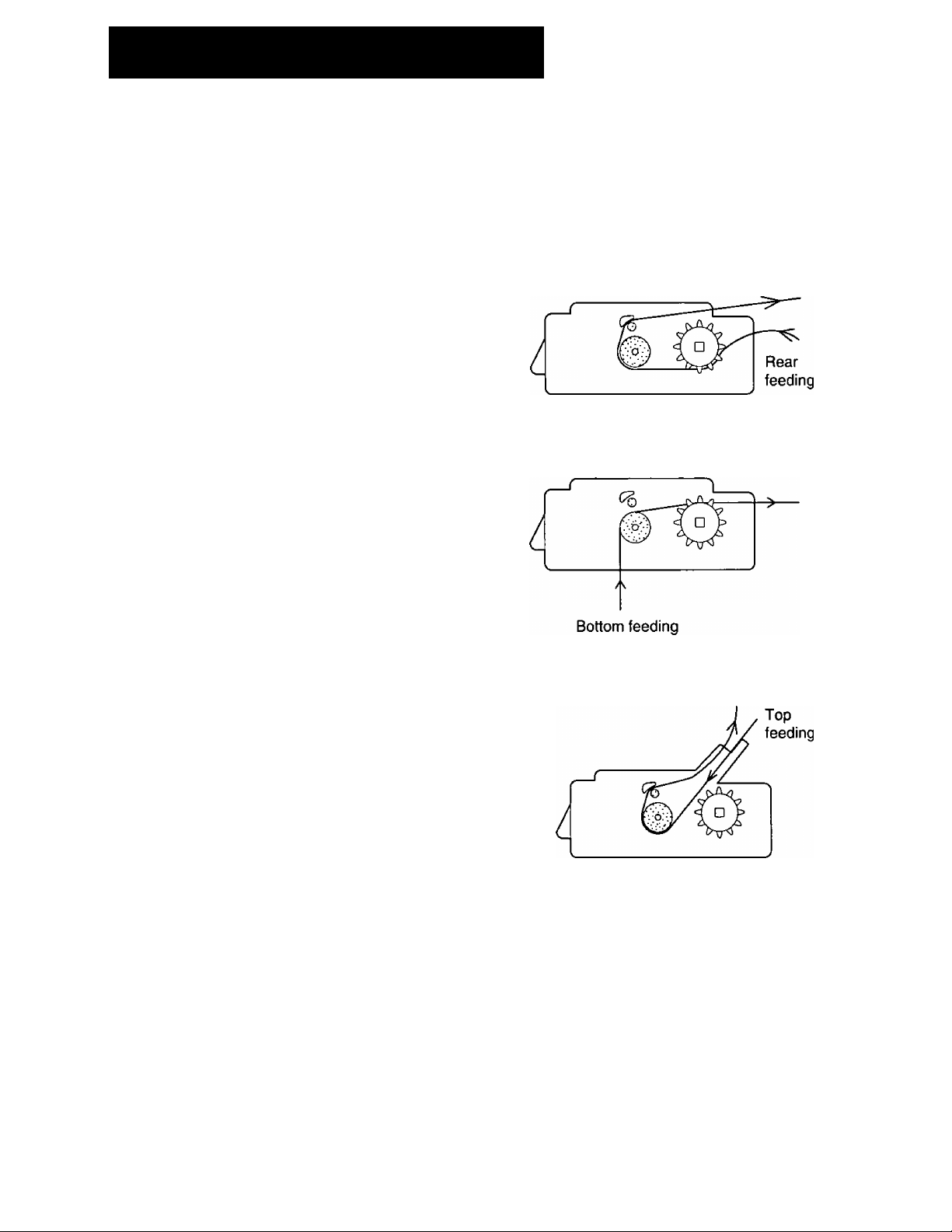
This printer has two paper feed mechanisms to support 3 paper paths. One mechanism is TRACTOR
mode for continuously fed paper. In the tractor mode you can choose between PUSH or PULL.
The other paper feed mechanism is FRICTION mode. In the friction mode you can feed single sheets
or envelopes through the top. The optional KX-PT10 Cut Sheet Feeder will accommodate automatic
feeding of single sheets, from the top paper path.
Push Tractor Mode
— fanfold paper (1 part)
— multipart forms consisting of 2 parts
Pull Tractor Mode '* [T| ” (Bottom Feeding)
— multipart forms consisting of 3 or 4
parts
— labels
— fanfold paper (1 part)
Friction Mode “ Q
ti [« ’I
(Rear Feeding)
— single sheets
(The KX-PT10 allows you to automatically
feed up to 80 sheets of 20 lb paper.)
— envelopes
Note:
• When feeding paper from the bottom, do not use reverse line feed. Paper may not feed
correctly and print quality may not be optimum.
• Paper Parking is not available when the paper is installed from the bottom.
• Multipart forms consisting of 2 parts may be used for rear feeding (Push mode). For 3 or
4 part forms, we recommend bottom feeding (Pull mode) for optimum print quality.
20
Page 21
Installing Paper
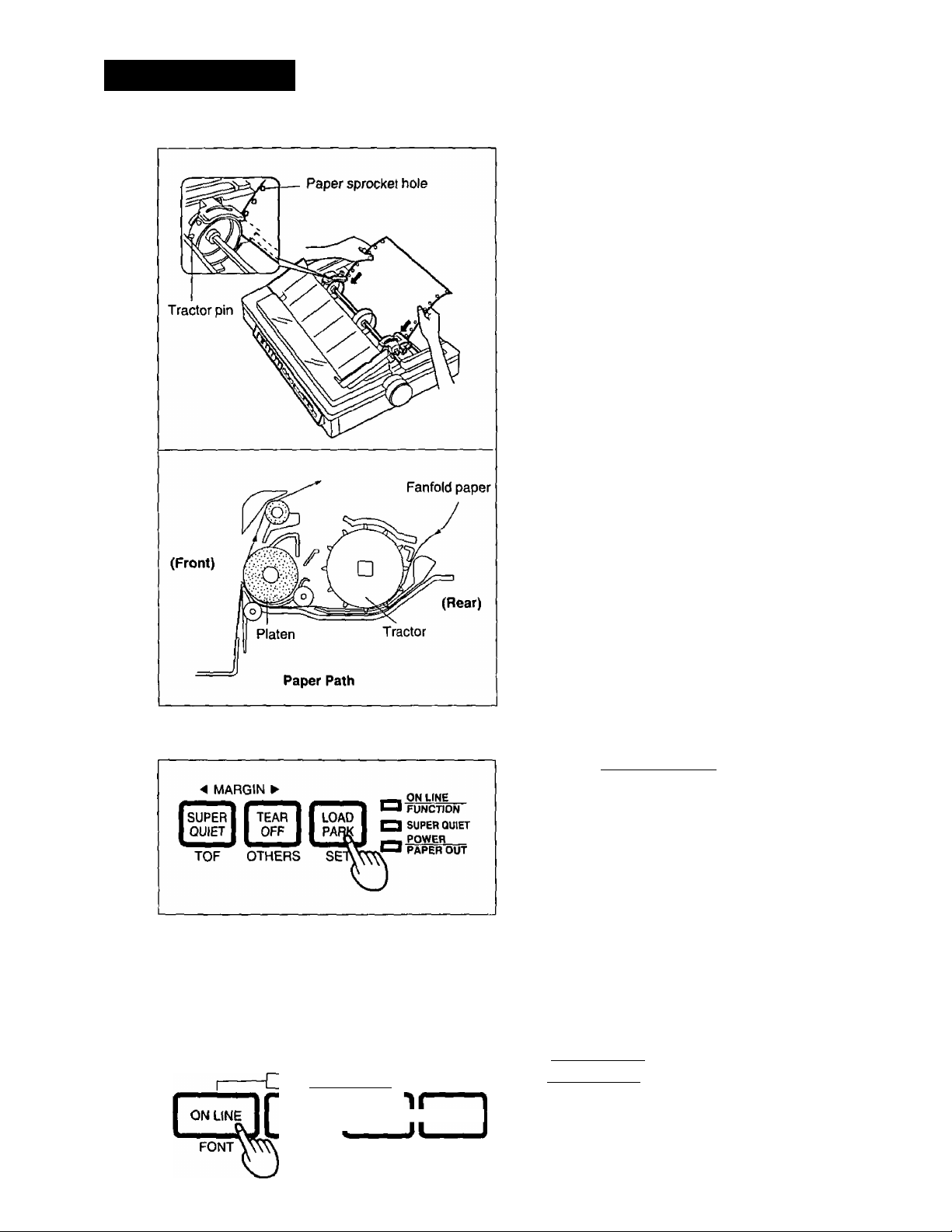
Fanfold Paper (Push Tractor Mode/Rear Feeding)
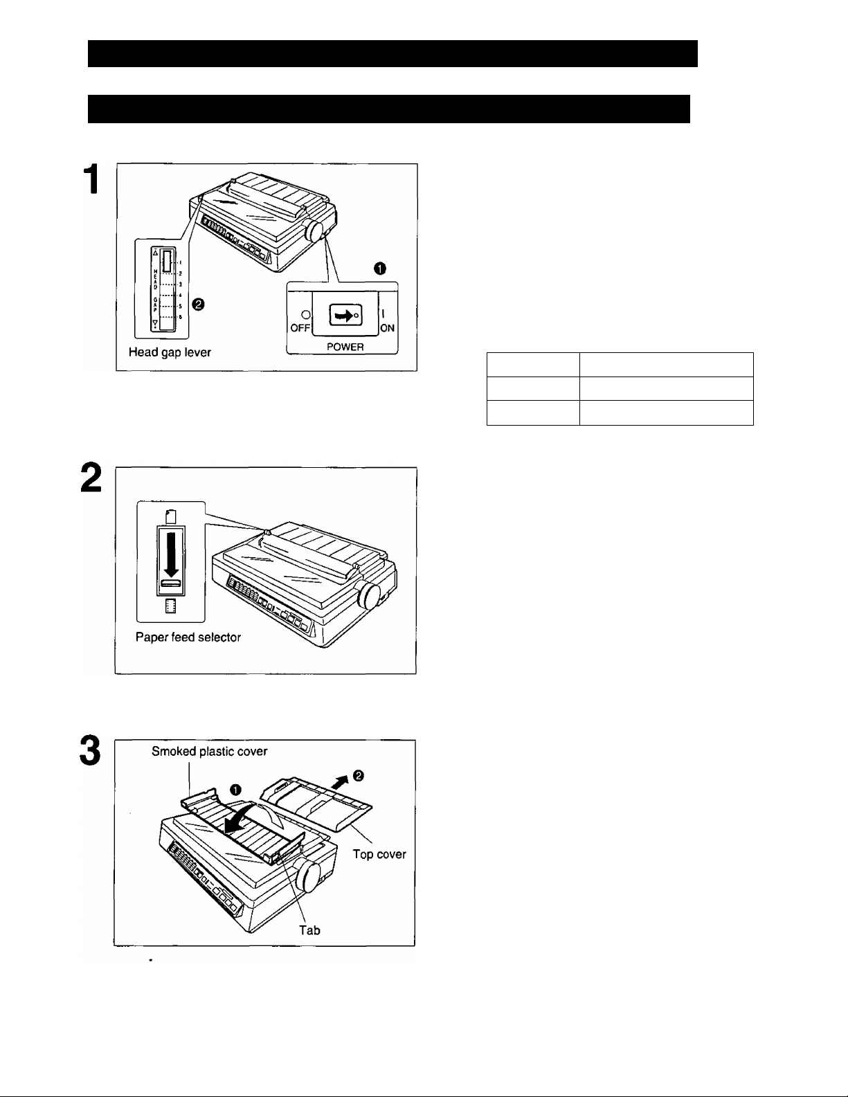
O Turn the power on.
You will hear a beep.
The PAPER OUT indicator will flash
indicating that paper is not installed in the
printer.
& Adjust the head gap lever for the
thickness of paper you are using.
Position
1 or 2
3, 4, 5 and 6
Set the paper feed selector to the
“ [Q] ” position.
O Fold the smoked plastic cover
forward by lifting the tab on right
side.
Thinner sheets
Thick or multiple sheets
Use for
@ Remove the top cover.
21
Page 22
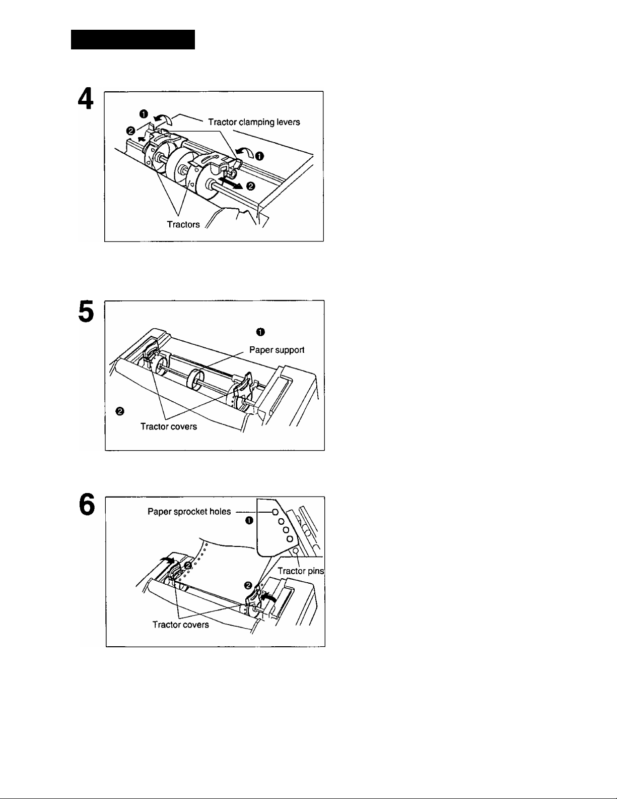
Installing Paper
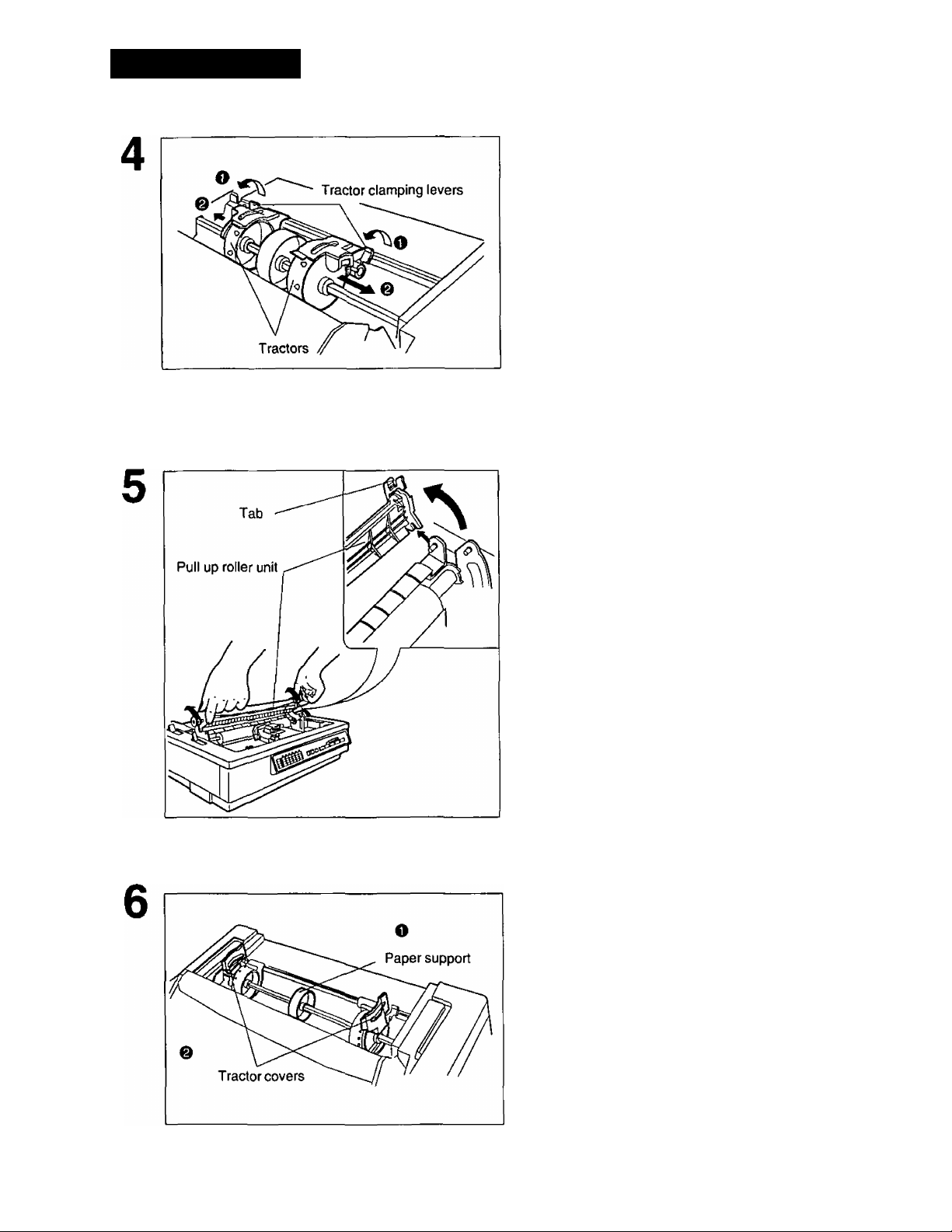
O Unlock the tractors by pulling the
tractor clamping levers forward.
0 Slide the tractors to opposite ends
of the printer.
Note:
• In most applications, you will find that
the 0 indicator on the tear bar is a
useful tool for predetermining your left
most print position.
Move the paper support to the
center position.
@ Open the tractor covers.
To set the tractors to the proper
width, align the paper sprocket
holes with the tractor pins by
moving the tractors.
Note:
• Make sure the paper is straight before
closing the tractor covers.
* •
O Close tractor covers.
22
Page 23
Open the tractor covers and remove
8
the paper, then close the tractor
covers.
Installing Paper
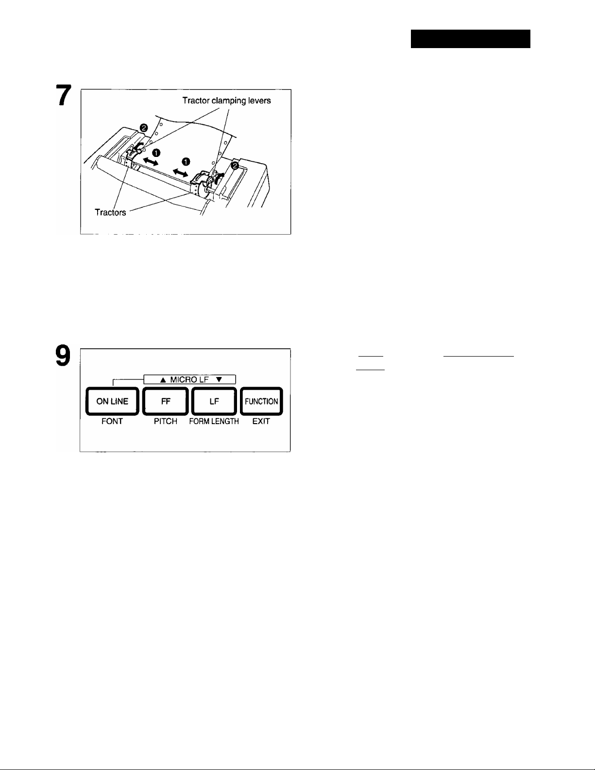
O Adjust the tractors to remove any
slack in the paper.
@ Lock the tractor clamping levers.
While holding down [ ON LINE ] ,
press [ FF ].
Note:
• This will cause the tractors to rotate
slowly for approximately 60 seconds.
23
Page 24
Installing Paper
10
While the tractors are rotating, insert
the fanfold paper evenly behind the
tractors, until the tractor pins catch
the paper sprocket holes.
11
1 2 cover to its original
* ^ position, then close the smoked
plastic cover.
r
13
24
MICRO LF T I
FF
PITCH FORM LENGTH EXIT
LF 11 FUNCTION I
Press rtOAD/PARI^ once.
Note:
• This will load the paper to the first print
line.
If the ON LINE indicator is not lit, press
fON LINE ] to get ready to print.
Note:
• To avoid paper curl in push mode, park the
paper after use.
Page 25
Fanfold Paper (Pull Tractor Mode/Bottom Feeding)
O Turn the power on.
You will hear a beep.
The PAPER OUT indicator will flash
indicating that paper is not installed in the
printer.
e Adjust the head gap lever for the
thickness of the paper you are
using.
Installing
Position
1 or 2
3, 4, 5 and 6
Thinner sheets
Thick or multiple sheets
Use for
Set the paper feed selector to the
“ (0] ” position.
Fold the smoked plastic cover
forward by lifting the tab on the
right side.
O Remove the top cover.
25
Page 26
Installing Paper
Unlock the tractors by pulling the
tractor clamping levers forward.
Slide the tractors to accommodate
e
the approximate width of the
paper you are using.
Note:
• In most applications, you will find that the
0 indicator on the tear bar is a useful tool
for predetermining your left most print
position.
Remove the pull up roller unit.
Note:
• Be sure to remove the pull up roller unit
before using the bottom feeding.
O Move the paper support to the
center position.
26
O Open the tractor covers.
Page 27
Installing Paper
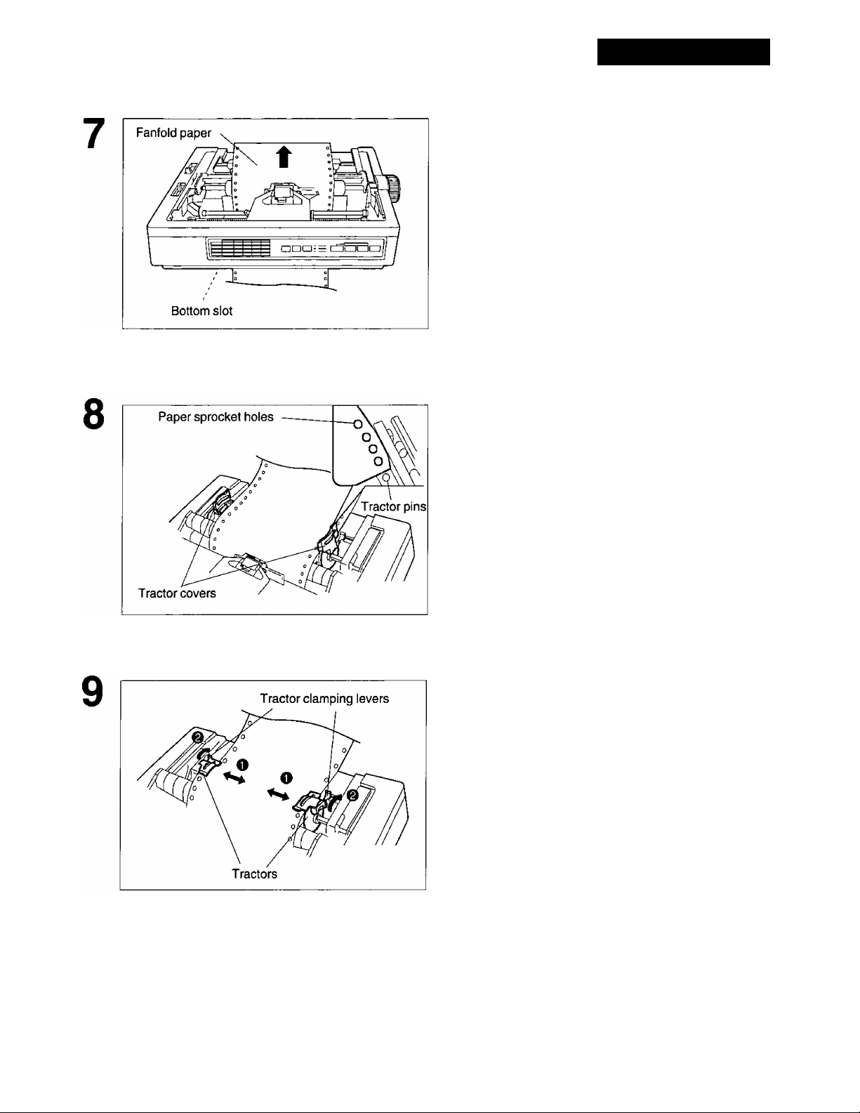
Push the fanfold paper up through the
bottom opening until it appears on the
platen.
Align the paper sprocket holes with
the tractor pins.
Make sure the paper is straight before
closing the tractor covers.
O Adjust the tractors to remove any
slack from the paper.
& Lock the tractor clamping levers.
27
Page 28
Installing Paper
10
Replace the pull up roller.
Note:
• Be sure to press down the pull up roller
unit it snaps into place.
11
12
Replace the top cover to its original position, then close the smoked plastic cover.
If the ON LINE indicator is not lit, press
[ ON LINE] to get ready to print.
Note:
• In the pull tractor mode (Bottom feeding), reverse line feed will not feed paper correctly
and the resulting printout may not be correct.
28
Page 29
Single Sheets and Envelopes (Friction Mode)
O Turn the power on.
You will hear a beep.
The PAPER OUT indicator will flash
indicating that no paper is installed in the
printer.
0 Adjust the head gap lever for the
thickness of the paper you are
using.
Installing Paper
Position
1 or 2
3, 4, 5 and 6
Thinner sheets
Thick or multiple sheets or
envelopes
Use for
Set the paper feed selector to the
“ Q ” position.
Fold the smoked plastic cover
forward by lifting the tab on the
right side.
0 Reposition the top cover into the
single sheet position by inserting
the top cover pins into the slots in
the printer.
These slots are indicated by black arrows
( ^ ^ ) on the printer cabinet.
29
Page 30
Installing Paper
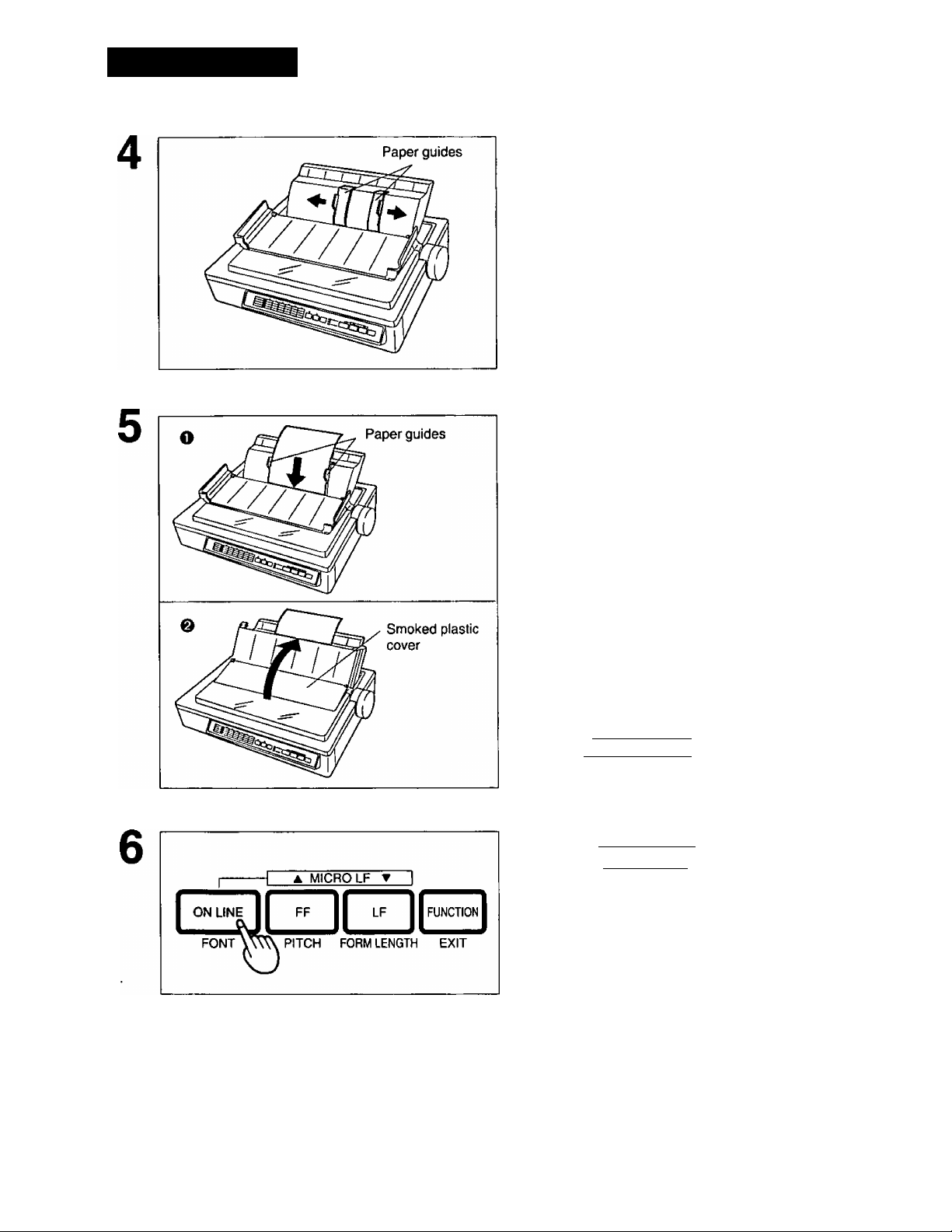
Separate the paper guides to the approximate width of your paper or envelope.
Note:
• To predetermine your left most print
position, move the left paper guide until
it clicks into place.
I
____
_________ __________ _
Insert a sheet of paper through the
paper guides and behind the
platen.
The paper will automatically load to the first
print line position.
Fold the smoked plastic cover
e
until it rests on the top cover.
Note:
• To disable Auto Load, turn Auto Load
off in the initial setup mode.
P.55)
• If Auto Load is disabled, press
[ LOAD/PARK] to automatically load
paper to the first print line.
If the ON LINE indicator is not lit, press [ ON line) to get ready to print.
30
Page 31

Installing Paper
Note:
• When Automatic load is set to off in the initial setup mode, press the [ LOAD/PARK] switch
to load the paper to the first print line.
• When the paper feed selector is in the “ p ” position, the buzzer will sound to inform you
that the selector is in the wrong position.
• When loading an envelope, if the envelope will not load smoothly, move the paper feed
selector to the “ ” position and insert the envelope manually, then move the selector
back to the “ Q ” position.
Characters Alignment
The center of all characters printed on this printer will be aligned with the ribbon mask line (RML).
The RML is a useful marker that shows you exactly where your print line is located.
Note:
• Remember that once you rotate the platen knob, the top of form (TOP) will no longer be recognized.
31
Page 32

Printer-Driver Selection
The Printer-Driver Selection contains the software codes your application software program uses to
access the printer’s features.
This procedure is the final step before printing and is performed in your application software program.
The steps will vary, depending on the software program. Consult your software package for proper
procedures. The Panasonic KX-P3123 wilt be your first choice. However, if the Panasonic KX-P3123
printer is not listed in your software, you must select an alternative from the following table.
Printer-Driver Selections (in order of priority)
Printer Selections
Panasonic KX-P3123 Panasonic KX-P3123
Panasonic KX-P3124 Panasonic KX-P3124
Epson LQ-570(ESC/P2™)
Panasonic KX-P2123 Panasonic KX-P2124
Panasonic KX-P2124 Epson LQ-860
Panasonic KX-P1124i Epson LQ-2500/2550
Epson LQ series
IBM Proprinter X24E
IBM Proprinter X24 *■'
*1
If selecting the IBM Proprinter X24E or IBM Proprinter X24 in your software, printer emulation
must also be changed in the initial setup mode. C®*p. 55-72)
*2
To obtain color and utilize the internal scalable fonts, the Panasonic KX-P3123 printer-driver must
be selected in your software.
Color Printer Selections
(KX-PCK11 Color Kit must be instalied)
Panasonic KX-P2123
32
Page 33

Installing a Printer-Driver (Windows Ver. 3.1)
If you are using Windows Ver. 3.1, please insert your setup disk in drive A or B and follow the
directions below.
Before you use the setup disk, it is recommended that you make a back-up copy and store the original
in a safe place.
Note:
* Use the DISKCOPY command of the operating system to make a back-up copy. Refer to your
DOS manual for further information.
In ‘‘Main Group”, select
1
“Print Manager”.
In “Options”, select “Printer Setup”.
Click Add »
In “List of Printers”, select “Install Unlisted or Updated Printer”.
Click Install...
r
Default Printer
xxxxxxxxxxxxxx
(- Installed Printer:
XXXXXXXXXXX
Set As Default Printer
Default Printer —
XXXXXXXXXXXXXX
r Installed Printer;
XXXXXXXXXXX
Set As Default Printer
Printers
Printers
m
m
*
Cancel
Connect...
Setup...
I Remove
I Add»
I Help
Cancel
Connect...
Setup,,, ]
Remove
Add»
I Help
List of Printers:
Install Unlisted or Updated Printer
[ Install... ^ ^
33
Page 34

Installing a Printer-Driver (Windows Ver. 3.1)
Insert the setup disk into drive A.
H you choose to insert the setup disk
into drive B, you must type B:\
Install-Driver
8
10
Click OK
Highlight your Panasonic Printer model.
Click OK .
Click Set As Default Printer
Insert unlisted, updated, or
vendor-provided printer driver disk in:
[sr
Add Unlisted or Updated Printer
List of Printers:
Panasonic KX-P3123
RTl
I
I Cancel I
I Browse... I
I Help ~]
L. OK -e
1 Cancel
1 Help
Click Close!.
11
12 Exit “Print Manager’
34
Page 35

Se
This printer has a self test feature which allows you to test the printer.
Load a sheet of paper (fanfold or single
1
sheet), then turn the power off.
P. 21-31)
While pressing [ LM , turn the power
on, then release.
Do not release f LFl until printing has
started.
A sample printout will begin, which
serves as a self test.
Version A
Draft
! "#$%&’(
I ’( )
)*+
’( )*+ ,
Courier
!"#$%&'(
!”#$%&*()
"#$%&'()*
#$%&*()*+
$%&'(}*+,
Prestige
! ’ (
"ft
+./0123456789:;<
./0123456789: ; <=->
)*+,-./0123456789:
*+,-./0123456789:;
+,-./0123456789:;<
,-,/0123456789:;<=
-./0123456789:;<=>
)*+,-./0123456789:
111,^1^1234 56789: ;
V0123456789:
./0123456789:i
./0123456789:;<-
9; :<
; < = >?@ABCDEFGHIJKLMNOF
<^>?@ABCDEFGHIJKLMNOPC
^>?@ABCDEFGHIJKLMN0PQF
> 78A8CDEFGHIJKLMN0PQR
Tt^ABCDEFGHIJKLMNOPQRS
;<=>?@ABCDEFGHIJKLMNOl
<=>?@ABCDEFGHIJKLMNOPi
->?@ABCDEFGHIJKLMNOPQ]
>?@ABCDEFGHIJKLMNOPQR
?@ABCDEFGHIJKLMNOPQRS'
: <->?0ABCDEFGHI.JKLMNO]
<=>?@ABCDEFGHlJKLMNOP{
= >?(aABC0EFGHIJKLMN0PQ]
>70ABCDEFGHIJKLMNOP
nHX
If the printer is functioning properly,
you may turn the power off during the
self test, or you may run the entire
test, (approximately 20 minutes.)
35
Page 36

SUPER QUIET Mode
The SUPER QUIET mode is a useful feature for further reducing print noise, however, it also reduces
the printer’s speed.
The printer can store this function in the MACRO as one of the printing conditions. To simplify the
MACRO setting process, you should set the SUPER QUIET mode before setting any other item on
the control table.
Turning on the SUPER QUIET mode:
■
c
«
5’
(Q
3"
(D
Be sure the power is on.
1
Note:
• Make sure the ON LINE/FUNCTION indicator
is not blinking. If it is blinking, press
[ FUNCTION I. j
i
Press [ SUPER QUIET ) to turn the SUPER
< MARGIN ►
SUPER
QUlEt
TOF^ l^HERS
3
TEAR
OFF
LOAD
PARK
SET
ON LINE
function
SUPER QUIET
POWER
PAPER OUT
QUIET mode on.
You will hear a beep and the SUPER QUIET
indicator will light.
Turning off the SUPER QUIET mode:
Be sure the power is on.
1
36
2
Press [ SUPER QUIET ] again to turn the SUPER QUIET mode off.
The SUPER QUIET indicator will not be lit.
Page 37

Feeding Paper
You can adjust the paper position by using the front panel switches when the printer is in the OFF
LINE mode or when the printer is not printing in the ON LINE mode.
Form Feed
With paper installed, pressing [ FF] moves the printhead to the center and advances the paper to the
next Top of Form (TOF) position.
Line Feed
With paper installed, pressing [ LF] once advances the paper one line. Holding the switch will move
the printhead to the center and advances the paper continuously until you release the switch.
Micro Line Feed
With paper installed, while pressing (ON LINE) , press [ FF] once to advance the paper one micro
line (1/180"). Holding the switch will advance the paper continuously until you release the switch.
Reverse Micro Line Feed
With paper installed, while pressing [ ON LINE ] , press (TQ once to reverse the paper one micro
line (1/180"). Holding the switch will reverse the paper continuously until you release the switch. The
printer cannot reverse the paper past the printable area, (b^ P. 93)
Note:
• Reverse Micro Line Feed will not work correctly in the pull tractor mode.
• When pressing [FF] or (TQ , the amount of paper which is fed is determined by the current
setting for lines per inch (Ipi). The Ipi is specified by the software command or through the control
panel.
Tear Off (Rear Feeding Only)
This function allows you to advance your fanfold paper’s perforation to the tear position. This is not
dependent on your Top of Form (TOF) position, but is dependent on your form length. After tearing
off the page, you can return your paper to your Top of Form. This function can be automatic through
the FUNCTION mode.
(D
Be sure the power is on.
1
Note:
• Make sure the ON LINE/FUNCTION
indicator is not blinking. If it is blinking, press
[ FUNCTION
i
37
Page 38

Feeding Paper
Press [ TEAR OFF] to advance the paper’s perforation to the tear bar.
Fold the smoked plastic cover forward by lifting tab on right side.
5*
(O
(D
"0
5'
(D
Close the smoked plastic cover.
Tear off the page, using the tear bar.
Press [TEAR OFF) to reverse the paper back to the Top of Form.
Note:
• A Top of Form setting (i®" P. 41) in the
non-printable area is ignored by Tear Off.
Tear Off will use the Top of Form setting
that was last saved.
If you do not press [TEAR 01^ the
second time, once data is received, the
printer will automatically reverse the paper
to the top of form position, if you choose the
automatic Tear Off function.
38
Page 39

Feeding Paper
Paper Parking (Rear Feeding Only)
This function allows you to use single sheets or envelopes without removing or wasting your fanfold
paper.
Parking the Fanfold Paper
Be sure power is on and the paper feed selector is in the “ [T| ” position.
1
Tear off the printed page(s) of the fanfold paper being used.
2
If the ON LINE/FUNCTION indicator is blinking, press ( FUNCTION ).
3
Press [ LOAD/PARK ] to reverse the fanfold
paper to the park position.
Loading Single Sheets or Envelopes
1
Move the paper feed selector to “ ”
(Friction mode).
O Fold the smoked plastic cover by lifting
tab on right side.
0 Raise the top cover to single sheet
position.
39
Page 40

Feeding Paper
1
Separate the paper guides and load a single
sheet or an envelope.
(i®* P. 29 “Single Sheets and Envelopes”) When
you are finished printing, remove the sheet (or
envelope) from the printer.
O Lower the top cover for fanfold paper.
(O
(D
■D
5’
& Replace the smoked plastic cover to its
original position.
Move the paper feed selector to “ ¡n] ”
(Push Tractor mode).
Press [ LOAD/PARK ] to reload the fanfold
paper to the Top of Form.
40
Page 41

Feeding Paper
Setting the Top of Form (TOF)
This printer has a Top of Form (TOF) function which stores the first print line position and loads the
paper to the designated position automatically. The first print line position will be stored even after the
power is turned off. Additionally, the printer can store 3 different Top of Form positions depending on
the paper feed method, [fanfold paper-push ( Q ), single sheet ( Q ) and single sheet using the cut
sheet feeder (option: KX-PT10)]
Be sure the power is on.
1
If necessary, redefine the FORM LENGTH of the paper you are using through your application
software or the printer’s control table (eg* P. 44).
Press { LOAD/PARK] to load the paper.
To redefine your paper’s first print line position, It is recommended to use your
application software. If this feature is not provided in your software, adjust the paper
position by using the Line Feed, Micro Line Feed, or Reverse Micro Line Feed.
(113=* P.37)
Press f FUNCTION ] to enter the FUNCTION
mode.
Note:
• Do not rotate the platen knob, otherwise the
printer will not be able to count the number of
lines.
41
Page 42

Feeding Paper
Press! SUPER quiet) (TOP) to set the Top
of Form for the current position.
Note;
• A Top of Form position (less than 5 inches from
the top of page) will be saved even after the
power is turned off. Pressing (LOAD/PARKl
will advance the paper to the most recently
saved Top of Form setting.
• A Top of Form position set in the area greater
than 5 inches will not be saved after the power
is turned off, after parking the paper, or after
using Tear Off.
• Temporary Top of Form setting is indicated by
one beep. Saved Top of Form is indicated by
two beeps.
• When you use fanfold paper, the Top of Form
position must be set on the first page because
the printer does not accept a top margin which
is longer than one page.
• When bottom feeding, do not use this function.
Press ( FUNCTION I (EXIT) to exit the
FUNCTION mode.
Press (ON LINE
1
to receive data.
42
Page 43

Setting the Control Table
While in the function mode, the black lettering (FONT, PITCH, FORM LENGTH, etc.) will help you
navigate through the Control Table. These settings will be temporary, unless stored in a MACRO.
Refer to page 48.
Printing Out the Current Settings in MACROS
Before changing any settings on the control table, you should verify the current settings.
Load a sheet of paper (fanfold or single sheet).
1
Press (FUNCTION I to enter the FUNCTION
mode.
The ON LINE/FUNCTION indicator will blink.
Press and release [TEAR OFF] (OTHERS)
until all the column indicators are blinking.
Press [ LOAD/PARK ) (SET) to print out the
current settings.
Press [ FUNCTION I (EXIT) to exit the
FUNCTION mode.
(D
43
Page 44

Setting the Control Table
Setting the FONT/PITCH/FORM LENGTH
Be sure the power is on.
1
Press [ FUNCTION I to enter the FUNCTION
mode.
The ON LINE/FUNCTION indicator will blink.
<D
3A
3B
3C
FONT
PITCH
FORM LENGTH
Press and release ( ON UNE I (FONT) to
reach the desired font. Go to step 4.
Press and release fFFl (PITCH) to reach
the desired pitch. Go to step 4.
Press and release [ LF ] (FORM LENGTH)
to reach the desired form length.
44
Page 45

4 MARGIN ►
SUPER
QUIET
TOF OTHERS setV^
TEAR
OFF PAF^
LOAD
ON LINE
FUNCTION
SUPER QUIET
POWER
PAPER OUT
Setting the Control Table
Press [ LOAD/PARK) (SET) to store the setting into the temporary memory.
You will hear a beep. The ON LINE/FUNCTION
indicator will stop blinking and be lit.
If you wish to make additional changes, refer to
step{s) 3A, B or C.
Note;
• When making multiple changes,
[LOAD/PARK] (SET) must be pressed after
each selection is made.
A
1
---------
ONLINE 1 FF LF
FONT PITCH FORM LENGTH EXIT
MICRO LF
T
Press ( FUNCTION
FUNCTION mode.
1
(EXIT) to exit the
(O
o
T3
(D
45
Page 46

Setting the Control Table
Setting the LEFT/RIGHT MARGIN
Be sure the power is on.
1
UHE
3^FUNCTK3N
SUPER own
ifOWFI
I?№rouT
A MICRO LF y I
ICDCZIC
PITCH FORM LENGTH EXIT
ionI
%
Press [^UNCTION ] to enter the FUNCTION
mode.
The ON LINE/FUNCTION indicator will blink.
Press and release[ TEAR OFF) (OTHERS)
until the column indicator is biinking over
the desired margin.
Press [ LOAD/PARKl (SET) to enter the
MARGiN mode.
The column indicator will be lit.
46
Page 47

4 MARGIN ►
TEAR
OFF PARK
HERS SET
LOAD
ON LtNE
FUNCTION
SUPER QUIET
POWER
PAPER OUT
Setting the Control Table
Press ( SUPER QUIET] (TOF) to move
the printhead to the left.
0
Press [ TEAR OFF ) (OTHERS) to move
the printhead to the right.
4 MARGIN ►
SUPER
QUIET
1 TEAR 1 LOAD
1 1
TOF OTHEM^ V SET
PARK
ON UNE
FUNCTION
SUPER QUIET
POWER
___
PAPER OUT
NOTE:
When the printhead is at the far
left, press ( SUPER QUiET] twice to
move it to the far right. You will hear
a beep a few times.
When the printhead Is at the far
right, press ( TEAR OFF ] twice to
move it to the far left. You will hear a
beep a few times.
Press [ LOAD/PARK] (SET) to specify the
margin location, and to exit the MARGIN
mode.
You will hear two beeps. The column inciicator will
blink.
Note:
• If the left margin is set to the right of
the right margin, the right margin is
reset to 80 (10 cpi) automatically.
• If the right margin is set to the left of'
the left margin, the left margin is reset
to 0 automatically.
(Q
(D
TI
Press ( FUNCTION ] (EXIT) to exit the
FUNCTION mode.
Note:
• You can set either the left or the right
margin first.
You can also change the margins by
software commands. This will
override the control table settings.
47
Page 48

Setting the Control Table
Defining MACRO (MACRO Save)
A MACRO allows you to store a combination of your most frequently used Font, Pitch, Form Length,
Left/Right Margin, Color, and Super Quiet mode settings into the printer’s memory which can be easily
recalled and/or changed. This will enable you to recall one of two combinations (MARCOs #1, #2) at
the touch of a button eliminating the need to reset all your features each time you have a print job that
uses a previously set combination.
When you turn the power switch on, the printer reads MACRO #1 automatically. Therefore it is
recommended to store the format you use most often in MACRO #1.
Be sure the power is on.
1
Press ( FUNCTION I to enter the FUNCTION
mode.
The ON LINE/FUNCTION indicator will blink.
to
3"
(D
■D
5'
<D
Set the print features you wish to store as the current settings. [FONT/PITCH/FORM LENGTH P.44), LEFT/RIGHT MARGIN (<^ P.46), COLOR (I®* P.53), SUPER QUIET (cs’ P.36)]
Note:
• COLOR can not be set without installation
of the color kit {KX-PCK11).
Press and release (TEAR OFF) (OTHERS) until the column indicator is blinking over MACRO #1 or #2.
48
Page 49

< MARGIN ►
I
SUPER
I
QUIET
TOP OTHERS
TEAR LOAD
OFF
PAF^I^
ON LINE
FUNCTION
SUPER QUIET
POWER
PAPER OUT
Setting the Control Table
Press (LOAD/PARK) (SET) to set the
MACRO mode.
You will hear a beep. The column indicator over your
desired MACRO will be lit.
RECALL*MACRO-SAVE
M MARGIN ►
SUPER TEAR LOAD
QUIET OF^ PARK
A
MICRO LF
SET
T
LF
TOP OTHE*
Z]
FONT PITCH FORM LENGTH E
ON LINE
FUNCTION
SUPER QUIET
POWER
PAPER OUT
Press [ TEAR OFF) [SAVE] to save the
current settings to the MACRO.
You will hear two beeps.
Press ( FUNCTION
1
(EXIT) to exit the
FUNCTION mode.
(Q
(D
“0
5‘
o
49
Page 50

Setting the Control Table
Recalling a Defined MACRO (MACRO Recall)
Be sure the power is on.
1
Press ( FUNCnoiT) to enter the FUNCTION
mode.
The ON LINE/FUNCTION indicator will blink.
Press and release [ TEAR OFF ] (OTHERS)
until the column indicator is blinking over
MACRO #1 or #2.
< MARGIN ►
ON UNE
FUNCTION
SUPER QUIET
POWER
PAPER OUT
Press I LOADTparITI (SET) to set the
MACRO mode.
You will hear a beep. The column indicator over your
desired MACRO will be lit.
Press ( SUPER QUIET ) [RECALL] to recall
the MACRO.
You will hear a beep. The previously defined MACRO
is recalled as a current setting.
Press (FUNCTION I (EXIT) to exit the
FUNCTION mode.
50
Page 51

Setting the Control Table
Recalling FACTORY Settings (Default Settings)
All of the original settings in the Function mode can be restored in the printer as they were originally
set when the printer was shipped. You can recall the factory settings anytime. {You cannot change
the factory settings. The MACROS settings are not canceled by recalling the factory settings.)
Be sure the power is on.
1
Press i FUNCTION ] to enter the FUNCTION
2
. 1---------------------------------------1 AMICROLFT^
^LJ ^RJM CnON
^3 S UPE R QU ET
_ POWER
— P APER OO T
ON LINE
FF LF FU NCTK)n|
PITCH FOFW LENGTH
exi tW^
mode.
The ON LINE/FUNCTION indicator will blink.
< MARGIN ►
ON LINE
FUNCTION
SUPER QUIET
POWER
PAPER OUT
Press and release [ TEAR OFF ) (OTHERS)
until the column indicator is blinking over
FACTORY.
Press ( LOAD/PARK
(SET) to set the
FACTORY mode.
You will hear a beep. The column indicator over
FACTORY will be lit.
51
Page 52

Setting the Control Table
A
MICRO LF
T
Press (SUPER QUIET) [RECALL] to recall
the FACTORY setting.
You will hear a beep. The FACTORY setting is
recalled as a current setting.
Press (function) (EXIT) to exit the
FUNCTION mode.
ON LINE
FONT PITCH FORM LENGTH EXIT
.jJ
LF
52
Page 53

Setting the Control Table
Setting a COLOR
Before you use this function, make sure that the color kit (KX-PCK11) is installed in the printer.
Be sure the power is on.
1
Press ( FUNCTION ) to enter the FUNCTION
mode.
The ON LINE/FUNCTION indicator will blink.
Press and release [TEAR OFF) (OTHERS)
until the column indicator is blinking over
COLOR (OPTION).
Press [ LOAD/PARK] (SET) to enter the
COLOR mode.
You will hear a beep. The OTHERS row indicator will
blink.
Press and release ( TEAR OFF ) (OTHERS)
until the column indicator combination is
blinking over your desired color.
53
Page 54

Setting the Control Table
< MARGIN ►
SUPER TEAR
QUIET OFF
TOF OTHERS
A
MICRO LF
T
ON LINE
FUNCTION
SUPER QUIET
POWER
PAPER OUT
Press ( LOAD/PARK] (SET) to store this setting into the temporary memory and exit the COLOR mode.
You will hear two beeps. The OTHERS row indicator
will be lit. The column indicator over COLOR will
blink.
Press ( FUNCTION ] (EXIT) to exit the FUNCTION mode.
ON LINE
FONT
FF
PITCH FORM LENGTH EXIT
CZ
FUNCTION
This printer allows you to select any one of the colors given in the table below.
COLOR
BLACK
RED (MAGENTA)
ORANGE
YELLOW
GREEN
BLUE (CYAN)
VIOLET
(Control table)
Cl
1 1
1 1
1 1
1' 1
1
--1—1
□
COLUMN Indicator
C2
1
___
) 1 1 1 i
□ 1
1 1 1—1
1 1
1
1
1 1
1 1
1__!
___
1 1 1
i—1
|.„ 1
C3 C4 C5
___
1 1
___
wm
1 1
1 1 1 I
1 1
ON
1
L_
C6
1
___
1 1
□□
□
:=OFF
1
* •
54
Note:
• C3, C4, C5 and C6 are used to represent the color selection Cl and C2 have no function
when selecting color.
• Only one color can be printed at a time. Multi-color printing may be accessible through your
application software.
Page 55

Using the Control Panel
Your Printer allows you to select 32 initial setup items.
You can use the control panel to select following 24 of all the initial setup items.
Emulation
Epson*
IBM.....................IBM Proprinter X24E
Character Set P.99)
Italic* (Epson only)
Graphic character set 1
Graphic character set 2
Code Page (d^ P. 99)
PC-437 (USA)*
PC-850 (Multilingual)
PC-860 (Portugal)
PC-863 (Canada-French)
PC-865 (Nonway)
PC-853 (Turkey)
International Character Set (c^ P. 104)
USA*
France Italy
@
Germany
U.K.
Denmark 1
Zero Font
0* (Normal zero)
0 (Slashed zero)
0 (Point zero)
Download Buffer Control
ON
OFF*
Cut Sheet Feeder
ON
OFF*
[C.S.F. option (KX-PT10) is installed.]
Paper Out Detector
ON*
OFF ....................Ignored
Buzzer Sound Control
ON*
OFF
Alternate Graphics Mode (AGM)
ON
OFF*
(This setting is effective only in the IBM
mode.)
................
Sweden
Spain 1
Japan
Nonway
.....................
..................
.....................
..................
....................
....................
...................
.....................
..................
Epson LQ-570
Denmark 2
Spain 2
Latin America
Korea
LEGAL
Enable
Disable
Enable
Disable
Active
Enable
Disable
AGM is ON
AGM is OFF
Auto LF
ON.......................CR+LF
OFF*
...................
Auto CR
ON.......................LF, VT, ESC+“J”+CR
OFF*
...................
(This setting is effective only in the IBM
mode.)
Skip Perforation
ON.......................1 inch
OFF*
...................
Graphic Direction
Uni*
.....................
Bi
.........................
Auto Tear Off
ON.......................Auto Tear Off
©
OFF*....................Manual Tear Off
(using TEAR OFF switch)
Interface
ON.......................Serial interface
OFF*
...................
(This setting is effective only when
KX-PS14 is installed.)
Data Length
ON.......................7 bit data length
OFF* ..................
Auto Loading
ON*
.....................
OFF
.....................
(This setting is ineffective when using the
fanfold paper or C.S.F.)
Baud Rate
150 2400
300 4800
600 9600*
1200
Parity Control
®
None parity* Odd parity
Ignore parity Even parity
CRonly
LF, VT, ESC+“J”only
No skip
Uni-directional printing
Bi-directional printing
Parallel interface
8 bit data length
Enabled
Disabled
0)
C/l
(D
c
XJ
5
o
a
o
* denotes setting when shipped from factory.
55
Page 56

Using the Control Panel
Protocol Select
ON
.....................
OFF* *
Remaining Buffer Capacity to Suspend
Data Transfer (S.D.T.) (X/OFF)
@
ON*
OFF
Remaining Buffer Capacity to Resume
Data Transfer (R.D.T.) (X/ON)
— When the S.D.T. is set to ON
ON*
OFF
— When the S.D.T. is set to OFF
ON*
OFF
...............
...................
...................
...................
...................
...................
...................
X/ON-X/OFF Protocol
DTR Protocol
128 byte
512 byte
256 byte
384 byte
640 byte
768 byte
@
L
* denotes setting when shipped from factory.
The control table is replaced with the following table.
Column indicator
Designation of Signal Polarity for DTR
Protocol Mode
NO
...................
OFF*
...............
Note:
• Items ® ~
optional KX-PS14 serial interface board is
installed.
. When the signal is
“space”, the printer tells
the computer that it cannot accept transferring
data.
. When the signal is
“mark", the printer tells
the computer that it can
not accept transferring
data.
will only appear when the
CO
<D
Row indicator
R1
R2
R3
R4
SUPER
QUIET
C=1
czt
dJ
CD
Cl C2 C3 C4
CD CD
/
------
-----
TEAR
OFF
Note:
• The rightmost column indicator is ignored.
• Each indicator is controled by using the keys below.
\
^
/ ' >
LOAD
PARK
___________
CD CD CD
f ' >
ON LINE
L
>
---------
(
------------
j
V
______
FF
\
/
V
f
----------
______
C5
1—1
\
LF
4
56
Page 57

Using the Control Panel
SUPER
QUIET
Ri ;c
R2 ZÜ
R3
R4 zc
ni ■
R2 c
R3 c
R4 C
R1
R2
R3
R4
R1
R2
R3
R4
R1
R2
R3
R4
R1
R2
R3
R4
R1
R2
R3
R4
R1
R2
R3
R4
R1 C
R2 C
R3 C
R4 I
RI
R2
R3
R4
R1
R2
R3
R4
RI
R2
R3
R4
RI
R2
R3
R4
RI
R2
R3
R4
RI
R2
R3
R4
RI
R2
R3
R4
s
J
f
L
TEAR
OFF
C1
I-------1
c
LOAD
PARK
J
L
C2
ON LINE FF
C3
C4
Print Current Initial Setup Condition
0
Epson
Italic G1 G2
USA Multilingual Portugal
Turkey
IBM
Canada-
French
0
USA France Germany U.K. Denmark 1
Sweden
Italy
Denmark 2 Spain 2
Download
Buffer
0
C.S.F.
Auto LF Auto CR Skip Perf. G. Direction
©
Interface
150 300 600 1200
4800 9600
None Parity
Protocol S.D.T. R.D.T.
Data Length
Ignore
Parity
Spain 1
Latin
America
P.O.
Detector
Auto
Loading
Odd Parity
Japan Norway
Korea Legal
Buzzer A.G.M.
©
Even Parity
Signal
Polarity
--------------
^
LF
C5
I I
Factory Read
Norway
Auto
Tear Off
2400
ROW indicator condition:
=light is lit i i =light is not lit V \ =light is blinking
57
Page 58

Using the Control Panel
Printing Out the Current Settings
Before changing the items of the initial setup mode, you should get a print out to verify the current
settings.
O Load a sheet of paper (fanfold or
1
OFF
0
h-H
POWER
single sheet).
& Turn the power switch off.
CO
(D
o
a
o
While pressing [ FUNCTION^), turn the
power switch on.
The ON LINE/FUNCTION indicator will
blink, and all the row indicators will be lit.
Press [TEAR OFF], [ LOAD/PARK),
( ON LINE ], or (?§ .
All current settings will be printed.
58
Press [ FUNCTibN] (EXIT) to exit the
FUNCTION mode, or continue by
proceeding to page 59, step 2, if you
wish to make changes.
Page 59

Setting the Initial Setup Mode
1
Using the Control Panel
While pressing [ FUNCTION), turn the
power switch on.
The ON LINE/FUNCTION indicator will
blink, and all the row indicators will be lit.
RECALL-MACRO-SAVE
< MARGIN
OTHERS SET
0» UNE
FUNCTION
SUPER QUIET
POWER
A M ICRO LF T 1
PITCH FORM LENGTH
Press and release [ SUPER QUIET)
until your desired row indicator
combination is lit. P. 57)
Note:
I • Row indicators will switch each time you
I
press[ SUPER QUIET).
Use (TEAR OFF) (C1), ( LOAD/PARK]
(C2), [ON LINE) (C3), (FF) (C4), and
[ LF] (C5) to change the settings of
the column indicators, P. 57)
Note:
• Each column indicator is simply
controlled by pressing one of the 5
switches.
u
(/)
£
c
TJ
o
a
(D
Press ( FUNCTION) (EXIT) to store
your selection(s) and exit the initial
setup mode.
59
Page 60

Using the Control Panel
Examples
1. While pressing [FUNCTION) , turn the power on.
2. Press and release ( SUPER QUIET] until the desired row indicator
combination is lit.
3. Use f fEAR OFF ] (Cl), [XOAD/PARK ] (C2). [ON LINE] (C3), [FF) (C4),
and fLF) (C5) to change the settings of the column indicators.
u
U)
(D
C
D
O
a
(D
4. Press (Function
mode.
Emulation; Press [ SUPER QUIET] once.
Epson Mode —^ Press [ LOAD/PARK]
B
Code Page: Press [SUPER QUIET] 3 times.
USA ---------------► Press [ LOAD/PARK
Download Buffer Control: Press [ SUPER QUIET] 8 times.
OFF
---------------
B
Cut Sheet Feeder: Press [ SUPER QUIET] 8 times.
1
(exit) to store the settings and exit the initial setup
IBM Mode
► Press [ TEAR OFF ]
1
----------------
Multilingual
CD
► ON
60
OFF
Auto Loading; Press [ SUPER QUIÉT) 10 times.
ON
Indicators condition:
Mli=tight is lit
i=light is not lit
------------
I—I
B
-------------
Press [ LOAD/PARK 1
Press ( ON LINE ]
ON
OFF
Page 61

Using the Control Panel
Resetting to FACTORY Settings
You can reset all the initial setup mode settings to the FACTORY settings anytime.
Follow the steps below.
While pressing [ FUNCTION] , turn the
power switch on.
The ON LINE/FUNCTION indicator will
blink, and all the row indicators will be lit.
Press [Tf^.
You will hear a beep.
Press [ FUNCTION
initial setup mode.
1
(EXIT) to exit the
61
Page 62

Using the Setup Disk
This printer allows you to select 32 initial setup items shown in the table below. You can select all
these items by using the setup disk.
CO
(D
O
a
(D
Menu
PRINT STYLE
EMULATION EMULATION
PAGE FORMAT
PRINT MODE G. DIRECTION
TEXT ENHANCEMENT
CHARACTER SET COUNTRY USA* JAPAN
FONT
PITCH
POINT SIZE 8* to 96 with 10.5 and 21
SKIP PERF.
P. LENGTH 11 INCHES* 8 INCHES
L. MARGIN
R. MARGIN 2 to 80* (10 CPI)
ZERO FONT NORMAL* SLASH
CHARACTER SET
CODE PAGE USA*
Item Setting
PROGRAM* SCRIPT
DRAFT SUPER LQ
BOLD PS COURIER SC
COURIER PRESTIGE SC
PRESTIGE ROMAN SC
ROMAN SANS SERIF SC
SANS SERIF
PROGRAM* 15 CPI
10 CPI 17 CPI
12 CPI PROPORTION
(every 2 points)
EPSON* IBM
1 INCH* NO SKIP (This condition can
12 INCHES 8.5 INCHES
14 INCHES 11^ INCHES
0* to 78 (10 CPI)
UNI* Bl
POINT
FRANCE NORWAY
GERMANY DENMARK 2
U.K. SPAIN 2
DENMARK 1 L. AMERICA
SWEDEN KOREA
ITALY LEGAL
SPAIN 1
ITALIC* GRAPHIC 2
GRAPHIC 1
MULTILINGUAL
PORTUGAL
CANADA FRENCH
NORWAY
TURKEY
“SC” is a scalable
font.
When -SC
sequences are
selected, PITCH is
automatically set to
PROPORTION.
POINT SIZE is
displayed only when
-SC sequences are
selected in FONT.
also be changed
through software
commands.)
(1^ P. 104
“International
Character Set")
(BS* P. 99
“Character Set
Tables”)
62
* denotes setting when shipped from factory.
Page 63

Using the Setup Disk
Menu Item
INSTALL
INTERFACE
Setting
AGM/IBM OFF* ON
AUTOCR/IBM OFF* ON
AUTO LF
AUTO LOADING
BUZZER ON*
P. 0. DETECTOR
QUIET MODE OFF*
TEAR OFF
CSF MODE OFF*
DOWNLOAD
COLOR
INTERFACE PARALLEL* SERIAL
DATA LENGTH 8 BIT*
BAUD RATE
PARITY NONE*
PROTOCOL DTR*
RDT SDT+128*
SDT RBC 128*
SIGNAL POLARITY
OFF* ON (This condition can
ON* OFF
OFF (This setting is
OFF* ON
ON
MANUAL* AUTO
ON [This setting is effective
OFF* ON
BLACK* RED
BLUE
GREEN YELLOW option (KX-PCK11) is
ORANGE
150 2400 (These settings are
300
600 9600*
1200
IGNORE EVEN
MARK* SPACE
VIOLET only when Color Kit
7 BIT
4800
ODD
XNO/OFF
SDT+256
RBC 512
{This setting is effective
only in the IBM mode.)
(This setting is effective
only in the IBM mode.)
also be changed
through software
commands.)
(This setting is effective
only when the paper
feed selector is in
position.)
available only for BEL
command.)
only when C.S.F.
option (KX-PT10) is
installed.]
[This setting is effective
installed.]
(This setting is effective
only when KX-PSI4 is
installed.)
effective only when
KX-PS14 is installed.)
SL
CO
m
o
Q«
(D
* denotes setting when shipped from factory.
63
Page 64

Using the Setup Disk
This setup disk can only be used in an IBM-PC or a compatibie computer with a 3.5"fioppy disk
drive.
Before you use the setup disk, it is recommended that you make a back-up copy and store the original
in a safe place.
This printer has been factory set to operate with most of the popuiar software packages, in
most cases there wiii be no need to change the initiai setup items. Refer to page 62 to verify
that the factory settings meet your requirements, if no changes are required, you shouid be
ready to print.
Note:
• Use the DISKCOPY command of the operating system to make a back-up copy. Refer to your
DOS manual for further information.
• You may find it convenient to install the Setup Disk programs directly onto your C Drive, rather
than reading them from the Setup Disk each time a change is necessary. Either method is
acceptable.
To perform an automatic installation of the Setup Disk files onto your C Drive, follow the steps
below:
u
CO
o
o
a
(D
1. Insert the Setup Disk into drive A or B.
2. Type A: (or B:) and press [ Enter].
3. Type INSTALL and press [Enter].
This procedure automatically creates a directory called 3123 and copies all of the programs
from your Setup Disk onto your C Drive.
At your C:\ >prompt, type CD 3123 and press [Ynter].
Type SETUP and press 1 Enter] to complete the procedure. Be sure to type this instruction as
one word.
if not, you will receive a Syntax error message.
64
Page 65

Using the Setup Disk
Running the Initial Setup Program
^ Insert your setup disk into either drive A or B.
<For DOS> <For WINDOWS>
O Type A: (or B:) and
2 Seiect Run from the Fiie menu.
^ press [ Enter ].
Q Type SETUP
Press ( Enter) .
You will receive a “Please Wait" message until your first screen automatically appears.
Q Type A:\SETUP (or B:\SETUP)
^ Click I OK I (or Press ( Enter)).
The first screen is an introduction to the operation of the Setup Disk.
Please read it through and press any key to continue.
------
The <Menu> window will be highlighted.
fp < Menu >
« Setup Utility (x * X K X X X X X x) » =
? PRrNTStyUEZrZI]
♦ EMULATION
♦ PAGE FORMAT
♦ PRINT MODE
♦TEXTENHANCEMENT
♦ CHARACTER set'
♦ INSTALL
♦INTERFACE
■; Item >
CFONTZ
PITCH
ZD
« COMMENT »
Select print style
« KEY OPERATION »
[Ft =HELP] [F3=SAVE TO DISK) [F5= PR I NT SETTINGS]
[F2=FACTORY SETTINGS] [FA^LOAD FROM DISK] [F10=SEND TO PRINTER] [ESC=EXIT|
.................
....
.
Note:
• You can proceed through the Setup Disk using a computer mouse or your arrow keys.
• (esc) exits you to DOS when you are at the <Menu> window.
Using the keyboard:
• (J) /(t) to move within the current window.
• 0 to advance to <ltem> and <Setting> windows.
• [ Enter] to make selection in <Setting> window.
• B to return to previous window.
Using the mouse:
• Highlight the selection and click the left mouse button.
• Click the right mouse button to move to the previous screen;
65
Page 66

Using the Setup Disk
Printing Settings
Before you change the initial setup mode settings, you can verify the settings by printing them.
Press
1
A Print Setting window will
be displayed.
2 Press [y] or
“Y”: All the settings (current,
MACROS, FACTORY) will
be printed.
“N”: The display will return to
previous screen.
-----
[=< Manu >
« Setup Utility (x X X K X X X X X x) » =
♦PHIMT STYLE
♦ EMULATION
♦PAGE FORMAT
♦PRINT MODE
♦TEXTENHANCEMENT
♦CHARACTER SET
♦ INSTALL
♦ INTERFACE
« COMMENT »
Select print style
_______
I — g Item a
:
Are you sure 7 (Y/N)
FONT
PITCH
[NOl
O
a
(D
Setting Selections on Setup Disk
In the <Menu> window,
1
press (J) or [J].
Select your desired menu
(ex; PRINT STYLE).
2 Press Q.
The <ltem> window will
be highlighted.
« KEY OPERATION »:
[FS^niNTSETnNGSI
tESC=EXI'n
66
0 Press (J]or U]
Highlight the desired item
(ex; FONT).
Page 67

Press @ ,
Using the Setup Disk
The <Setting> window will be
highlighted.
C Press (T| or (Л
Highlight the desired setting
(ex; DRAFT).
Press f Enter] .
The desired item has been set.
A V will appear next to the new
setting.
^ Press Щ.
The <ltem> window will be
highlighted.
To make additional changes in
the <ltem> window, repeat steps
3to 6.
^— « Setup Utility (x X X X к Д x x x x) »
rF< Menu >
r^PRINTT STYLE !
♦ iMULATION
♦ PAGE FORMAT
♦ PRINT MODE
♦TEXT ENHANCEMENT
♦CHARACTER SET
♦ INSTALL
♦ INTERFACE
« COMMENT » =
Select font style
Style of typeface.
♦SC is SCALABLE FOTN.
« KEY OPERATION » —
[F1=HELP1 [F3=SAVE TO DISK] [F5=PRINT SETTINGS]
[F2=FACTORY SETTINGS] [F4=LOAD FROM DISK] [F10=SEND TO PRINTER] [ESC=EXT]
------
- < Menu > ■
« COMMENT »
Select font style
Style of typeface.
♦SC is SCALABLE FONT.
« KEY OPERATION ■ ■
[F1=HELP] [F3=SAVE TO DISK] [F5=PRINT SETTINGS]
[F2=FACTORYSETTINGS] [F4=LOAD FROM DISK] [F10=SEND TO PRINTER] [ESC=EXIT]
« Setup Utility (x xxxxx xxxx)» -—
¡♦PR]nt STYLE
♦ EMULATION
♦ PAGE FORMAT
♦ PRINT MODE
♦TEXTENHANCEMENT
♦CHARACTER SET
♦ INSTALL
♦INTERFACE
ttetti >
'FONT'
PITCH
~ < Item > :
[TFont_
PITCH
< betting
R PROGRAM
DRAFT П
BOLD PS
COURIER
PRESTIGE
ROMAN
SCRIPT
SANS SERIF
SUPER LQ
COURIER SC
PRESTIGE SC
ROMAN SC
SANS SERIF SC
—< Sotting >
PROGRAM
V DRA0G
BOLD PS
COURIER
PRESTIGE
ROMAN
SCRIPT
SANS SERIF
SUPER LQ
COURIER SC
PRESTIGE SC
ROMAN SC
SANS SERIF SC
-------
(/}
Ф
О
a
о
g Press @ .
The <Menu> window will be
highlighted.
To make additional changes in
the <Menu> window, repeat
steps 1 to 6.
= « Setup Utility (x X X X X X xxxx)»
Menu >
"♦PRiNT STYLE
♦EMULATION
♦ PAGE FORMAT
♦PRINT MODE
♦TEXT enhancement
♦CHARACTER SET
♦ INSTALL
♦INTERFACE
« COMMENT »:
Select print style
« KEY OPERATION ' " ■
[F1 =HELP] [F3=SAVE TO DISK] [F5=PR I NT SETTINGS]
[F2=FACTORY SETTINGS] [F4=LOAD FROM DISK] [F10=SEND TO PRINTER] [ESC=EXIT]
...........
.
--------
67
Page 68

Using the Setup Disk
When all changes have been made, you may perform any one of the following operations:
Save to Disk - [F3) (ns* P. 68)
Print Settings - (F5]_te P. 66)
Send to Printer - [ FIOl {u^ P. 69)
Press [esc) .
10
An Exit window will be displayed.
Press ® or ® .
11
“Y": You have exited the Initial
Setup program.
“N”; The display will return to
the <Menu> window.
------
|- < Menu >
« KEY OPERATION »
[FI^HELP]
[F2=FACT0RY SETTINGS] [F4=LOAD FROM DISK] [F10=SENO TO PRINTER] ESC=EXIT
« Setup Utility (x xxxxx xxxx)»
rrpRifir STYLE
♦ EMULATION
♦ PAGE FORMAT
♦ PRINT MODE
♦ TEXT ENHANCEMENT
♦ CHARACTER SEI
♦ INSTALL
♦INTERFACE
« COMMENT »
Select print style
■p < Item >
PFONT'
PfTCH
Exit to DOS ? (Y/N)
[NO]
[F3=SAVE TO DISK] [F5=PRINT SETTINGS]
U
CO
S
c
T3
o
a
(D
Save to Disk
Press ipsl.
1
A Save to Disk window will
be displayed.
Enter a file name (up to 8 cha
racters, upper or lower case).
Press [^nter]
All the settings will be saved
on the disk and the display will
return to the <Menu> window.
A Press ( esc) , to exit to DOS.
= « Setip Utilitv (x X X X X X xxxx)»
Menu >
nPRItfrSTVllE
♦EMULATION
♦ PAGE FORMAT
♦PRINT MODE
♦TEXT ENHANCEMENT
♦ CHARACTER SET
♦INSTALL
♦INTERFACE
« COMMENT »
Select print style
« KEY OPERATION »;
Rle name ■
fiSiSAVE.TODlSK]
f-=< Item >
---
••DAT
(Type filename: Enter)
(ESC=EXrn
68
Page 69

Load from Disk
Press [ F4 ].
1
A Load from Disk window will
be displayed.
Use or [J] to highlight
your desired file name.
f^< Menu >
r*PfllNT STYLE"
♦emulation’
♦ PAGE FORMAT
♦ PRINT MODE
♦TEXT ENHANCE^
♦CHARACTER SE"
♦ INSTALL
♦ INTERFACE
Using the Setup Disk
« Sehjp Uility (x X X X X K x x x x) » =
r-< iiem > ——
FONT
PITCH
File name : (T t to highlight; Enter)
xxxx.DAT
xxxxxxxx.DAT
xxxxx.DAT
xxxxxx.DAT
DAT
XXX.
Press Enter
All the settings in the file
will be loaded to your screen.
To transfer these settings to
your printer, you must perform the
[FIO] Send to Printer operation:
{US’ P.71)
Send to Printer
^ Press ( FI O ].
A Port Selection window will
be displayed.
Note:
• Before setting the Port
selections, it is recommended
to print out the current settings
of your printer (i®* P.58). Set
the Port selections so as to
match the settings of your
printer.
« COMMENT »
Select print style
KEY OPERATION » :
r?: < Menu > =
ITprint^style”
« COMMENT » :
Select print style
« KEY OPERATION
« Setup Utility (x X X X X X x x x x) » =:
♦EMULATION
♦PAGE FORMAT
♦PRINT MODE
♦TEXTENHANCEMEI
♦CHARACTER SET
♦INSTALL
♦INTERFACE
F:4=L0AD;FROM DISK!
— < Hem a —
rrowr !
Port selection
PORT
BAUD RATE
PARITY
DATA LENGTH
PROTOCOL
Send to Printer (Y/N)
[YES] [NO]
[9600]
[NONE]
[8 bit]
[DTR]
[ESC=EXIT]
i[1 : LPTi]
[2; LPT2]
[3; LPT3]
[4: COM1]
[5: COM2]
FICfiSENpjroPBTT^ [ESC=EXIT]
CO
a
c
■D
a
(D
2 Press U) or U] .
Select the desired Port selection
item, (ex; PORT)
69
Page 70

Using the Setup Disk
2 Press Q .
A Selection window will be
displayed.
A Press [t] or [T] .
Highlight the desired setting
(ex: LPT1).
Press Enter
The desired item has been set.
0 Press @ .
To make additional changes in
the Port selection menu, repeat
steps 2 to 5.
=:« Setup utility (x X X me X x x x x) »
7= < Menu >
»PRIHT STYLE
♦ EMULATION
♦ PAGE FORMAT
♦ PRINT MODE
♦TEXTENHANCEMEl
♦CHARACTER SET
♦INSTALL
♦ INTERFACE
« COMMENT » :
Select print style
« KEY OPERATION »:
r=< Item >
PORT
BAUD RATE
PARITY
DATA LENGTH
PROTOCOL
Send to Printer (Y/N)
[YES] [NO]
[9600]
(NONE)
(6 bit]
[DTR]
IBOiSEimOjraiNTEB [ESC=EXIT]
ifli)
LPT2]
LPT3]
COM1]
COM2]
u
CO
(D
c
*o
o
d
(D
Press [T] until YES is highlighted.
0 Press (y] or ® .
“Y’: All the settings will be sent
to the printer.
“N": The display will return to
the <Menu> window.
Press [ESC] , [y] to exit
to DOS.
= « Sotip Utility (x X X X X X X X X x) »
;= < Menu > :
♦EMULATION
♦PAGE FORMAT
♦PRINT MODE
♦TEXTENHANCEME
♦ CHARACTER SET
♦ INSTALL
♦ INTERFACE
« COMMENT » :
Select print style
« KEY OPERATION »;
PORT
BAUD RATE
PARITY
DATA LENGTH
PROTOCOL
Send to Printer (Y/N)
irygsil [NO]
LPT1
[9600]
[NONE]
[8 bit]
[DTR]
IF.i05SEND.'nj;PBINTEft (ESC=EXIT1
1(1“
[2
[3
[4
[5-
LPTil
LPT2]
LPT3)
COMt]
COM2]
70
Page 71

Resetting to FACTORY Settings
^ Press .
Using the Setup Disk
Press ® O'' ® ■
ii^\
All the settings will be
reset to FACTORY
settings.
w
The display will return to
the <Menu> window.
If (3 was selected, you may
perform one of the following
operations:
Save to Disk — [F3] (P. 68)
Print Settings — fF^ {^ P. 66)
Send to printer — fFiOl P.69)
^ Press (esc) , (Y1 to exit to DOS.
Menu >
DlPRJNISWLE
♦EMULATION
♦ PAGE FORMAT
♦ PRINT MODE
♦TEXT ENHANCEMENT
♦CHARACTER SET
♦ INSTALL
♦ INTERFACE
« COMMENT »
Select print style
« KEY OPERATION »:
« Setup Utility (x X X X X X x x x x>» =
[F2iFACTORY:SETnNGS!
Item > =
TFONT“
PITCH
Are you sure ? (Y/N)
fYESl NO
I
[ESC=EXrn
Help
When you cannot remember what a particular function is, HELP will show you the explanations of the
functions.
^ Press [ F1 ].
A Help Item screen will
be displayed.
2 Press @/ @ / [t] / g]
Highlight your desired item.
(ex; AGM/IBM)
<AUTOCFVIBM> <FONT>
<AUTO LF>
<AUTOLOADING> «INSTALU
<BUZZER> <INTERFACE> «QUIET MODE>
«CHARACTER SET>
«CODE PAGE> «LEFT MARGIN> «SERIAL>
«COLOR> «PAGE LENGTHS
«COUNTRY> «P.O.DETECTOR>
«CSFMODE> «PAGE FORMAT>
«DOWNLOAD> «PARAaEb. «ZERO FONT>
.r.r KPY nPFRATIDN PflR HFI P ------------------------------------------------------------------------------------------
m
[^] [^)
[il
<EMUUTION>
<G.DIRECTION> «PRINT MOOE>
<ITALIC>
[ENTER KEY)
«PITCH>
«POINT SIZE>
«PRINT STYLE>
«RIGHT MARG)N>
«SKtPPERFORATION>
«TEAR OFF>
«TEXT ENHANCEMENT>
(ESC=EXIT)
71
Page 72

Using the Setup Disk
0 Press ( Enter ).
A definition will be displayed.
Press ESC
The Help Item screen will be
displayed.
Press [esc] .
5
The display will return to the
<Menu> window.
:« HELPfTEM ».
5AGM/iBM3 <EMULATION> <PITCH>
<AUTO CfVIBM> <FOMT> <P01^П■ SIZE>
<ALTTO LF> <G,DIRECTION> <PRI^П■ MODE>
<AUTO LOADING> <INSTALL> <PRINT STYLE>
<AGM/I8M>
The alternate graphics mode (AGM) will allow you to select
Epson graphics while in the IBM mode. If what you printed Is
not exactly what is on the screen, but there is a symbol that
is replacing the symbol you expect, change the character set.
« KEY OPERATION FOR HELP » —
IÎ]
[r-I [->1 [ENTER KEY]
\i]
(ESC=EXIT|
u
C/)
S
c
*o
o
a
(D
72
Page 73

Epson ESC/P2 Mode (Epson LQ-570 Mode)
This section is for the development of programs and printer-drivers and assumes the reader is proficient
in programming. More detailed information has been stored in the command reference program on
the setup disk.
Font Selection
Function
Selects print quality
Selects print typeface
Selects sub/superscript printing ESC “S" n
Releases sub/superscript printing
Selects font by pitch and point
ESC V n
ESC “k” n
ESC T”
ESC “X" m ni n2
Name Parameter
n=0: Draft font
n=1: LQfont
n=2: SLQ mode (Roman 5,10, 6,
and 12 CPI fonts only))
n=0: Roman
n=1: Sans Serif
n=2: Courier
n=3: Prestige
n=4: Script
n=6: Bold PS
n=0: Superscript
n=1: Subscript
0 g m g 127 except 2,3 and 4
m=0: No change to character spacing
m=1: Character spacing is set to PS
m>4: Sets character spacing to ^°/m
CPI
(O^ni g255)DEC (0^n2^127)DEC
ni=0 n2=0: No change to point size
[Total points]=("‘''^^^2®®V2
Character Pitch Selection
Function Name
Sets pica pitch (10 cpi) printing
Sets elite pitch (12 cpi) printing*
Sets micron (15 cpi) printing
Sets compressed (17 cpi) printing*
Releases compressed printing
Sets/Releases proportional spacing
Sets programmable pitch/
highlighting based on the value
of n
ESC “P"
ESC “M"
ESC "g”
SI or ESC SI
DC2
ESC “p" n
ESC “!” n
n=0: Release
n=1: Set
(0^n^255)oEC
n=0: Pica n=16: Double-strike
n=1: Elite n-32: Double-width
n=2: PS n=64: Italic
n=4: Comp. n=128: Underlining
n=8: Emphasized
* When elite and compressed pitches are set simultaneously, subsequent output is printed in
20 cpi (up to 160 cpI).
Parameter
73
Page 74

Epson ESC/P2 Mode (Epson LQ-570 Mode)
Character Highlight Selection
Function
Sets emphasized printing
Releases emphasized printing
Sets/Releases double high printing ESC V n
Sets single-line double wide printing
Releases single-line double wide DC4
printing
Sets/Releases double wide printing
Sets outline and shadow printing
Sets double strike printing
Releases double strike printing
Sets/Releases underlining
ESC “E"
ESC “P
SO or ESC SO
ESC "W” n
ESC “q" n
ESC “G”
ESC “H”
ESC n
Name Parameter
n=0: Release
n=1: Set
n=0: Release
n=1:
Set
n=0: Releases outllne/shadow
n=1:
Outline
n=2:
Shadow
n=3: Outline with Shadow
n^O: Release
n=1:
Set
Sets/Releases score
ESC “(” “-”3 0 1 di d2
Word Processing Mode Selection
Function
Sets character dots spacing
Sets unit
Sets horizontal motion index (HMI)
ESC SP n
ESC “(” “U” 1 0 m
ESC “c" ni n2
Name
di=1: Underline
di=2: Strikethrough
di=3: Overscore
d2=0: Cancel the score line
selected by di
d2=1: Single continuous line
d2=2:
Double continuous line
d2=5: Single broken line
Double broken line
d2=6:
Parameter
(0^n^127)DEC
m=10, 20, 30, 40, 50, 60
(unit='"/3600inch)
HMl=ni+02x256
(O^ni S255)DEC (0gn2^4)DEC
74
Page 75

Epson ESC/P2 Mode (Epson LQ-570 Mode)
Character Set Selection
Function Name
Sets Italic printing
Releases Italic printing
Sets international character set ESC “R” n n=0
Selects graphic character set 1
Selects graphic character set 2 ESC “6”
Selects alternate character set ESC T n
Assign character table
ESC “4”
ESC V
ESC “7”
ESC T T 3 0 ni n2 0
n=1
n=2
n=3
n=4 Denmark 1 n=12: Latin
n=5
n=6 Italy n=13: Korea
n=7
n=0:
n=1: PC437 (US)
n=2: User-defined characters
n=3: PC437 (US)
(0^ni^3) (48sni^51) (0Sn2^255)
n2=0: Italic
n2=1 : PC437(US)
n2=3
n2=5: PC853 (Turkey)
n2=7
n2=^
n2=9
Parameter
USA n=8; Japan
France n=9: Norway
Germany n=10: Denmark 2
UK n=11: Spain 2
Sweden America
Spain 1 n=64: Legal
Italic
: PC850 (Multitigual)
: PC860 (Portugal)
: PC863 (Canada-French)
: PC865 (Norway)
Prints data as character
ESC “(" m na Data (O^ni g255)DEC (0^n2^125)DEC
Bit Image (Graphics) Mode Selection
Function Name
Sets 8-pin image standard density ESC “K" ni n2 Data
(60 dpi)
Sets 8-pin image double density ESC “L” ni n2 Data
(120 dpi)
Sets 8-pin image double density/ ESC “Y” ni n2 Data
double speed (120 cpi)
Sets 8-pin bit image quadruple ESC “Z” ni n2 Data
density (240 dpi)
Sets bit image mode selection
ESC m ni 02 Data 8-pin Dots^nch 24-pin Dots/Inch
m=0
m=1
m=2
m=3
m=4
m=6
Parameter
60
120
120D
240
80
90
m=32
m=33
m=38
m=39
m=40
60
120
90
180
360
75
Page 76

Epson ESC/P2 Mode (Epson LQ-570 Mode)
Bit Image (Graphics) Mode Selection (Continued)
Function Name Parameter
Reassigns graphics mode density ESC n m n=75: Reassign Standard Density
(ESC “K” ni n2)
n-76: Reassign Double Density
(ESC “L” m 02)
n=89: Reassign Double Speed,
Double Density (ESC “Y” ni ri2)
n=90: Reassign Quadruple Density
(ESC “Z” ni n2)
m is same as m of “Sets bit image
mode seiection"
Selects graphics mode
Prints raster graphics ESC “." c V h m ni n2
ESC T “G” 1 0 n
Data
Paper Feed Selection—Amount
Function Name Parameter
Sets paper feed to Vs inch (3.2 mm) ESC “0"
Sets paper feed to Ve inch (4.2 mm) ESC “2"
Sets paper feed to "/eo inch
Sets paper feed to "Лео inch ESC “3” n
Sets paper feed to ^/зео inch ESC “+” n
ESC “A” n
Paper Feed Selection
Function Name Parameter
Feeds paper one line LF
Feeds paper to next Top of Form FF
n=1,49
c=0, 1 v=10,20 h=10,20
(1 ^ m S24) (0 ^ ni ^ 255)dec
(0gri2g127)DEC
(О^пё 127)dec
(0^n^255)oEC
(0^n^255)DEC
76
Executes paper feed of "/leo inch
for one line
Executes reverse paper feed of
"/leo inch for one line
Page Format Selection
Function Name Parameter
Sets page length in inches
Sets page length in lines
Sets left margin
Sets skip perforation
ESC “J" n
ESC T n
ESC “C" 0 n
ESC “C" n
ESC T n
ESC “N” n
(Oén^255)oEC
(0sn^255)DEC
(0 ^ n ё 22)dec
(1 ^nSl27)DEC
0sn^78: Pica
0^n^93: Elite
0^n£l17: Micron
0^n^133: Compressed
(1 ^пё 127)dec
Page 77

Epson ESC/P2 Mode (Epson LQ-570 Mode)
Page Format Selection (Continued)
Function
Sets right margin
Releases skip perforation ESC “0"
Sets page length in defined unit
Sets page format
ESC “Q” n 2^ng80: Pica
ESC T “C" 2 0 ni na
ESC X "c” 4 0 mi m2 ni n2 m=mi+nri2x256
Tabulation—Horizontal
Function
Sets horizontal tab
Releases horizontal tab
Executes horizontal tab
ESC “D” ni ... nx 0
ESC “D" 0
HT
° Name
3^n^96: Elite
3^n^l20: Micron
4 ^ n ^ 137: Compressed
n=ni+02x256
m: Top margin in defined units
n+ni+02x256
n: Bottom margin in defined units
Name Parameter
(1^xg32)
Parameter
Tabulation—Vertical
Function Name
Sets vertical tab
Releases vertical tab
Executes vertical tab
ESC “B” ni ... nx 0 (1^x^16)
ESC “B” 0
VT
Carriage Control
Function
Prints, then backspaces one
character
Prints a line, then returns carriage CR
Unidirection mode (single line) ESC “<”
Sets/Releases single direction
printing
Sets/Releases half speed printing
Moves the print position to an ESC T ni n2
absolute horizontal position
BS
ESC “U” n
ESC “s" n
Name
Parameter
Parameter
n=0: Release n=1: Set
n=0: Release n=1: Set
n=n 1+02x256
(0 ^ ni g 255)dec (0 g 02 S 1 27)dec
Moves the print position to a ESC T ni n2
relative horizontal position
n=ni+02x256
(0^ ni S 255)dec (0^ 02S 127)dec
77
Page 78

Epson ESC/P2 Mode (Epson LQ-570 Mode)
Carriage Control (Continued)
Function Name Parameter
Sets absolute vertical print position
ESC T “V” 2 0 ni n2
(0 ^ ni ^ 255)DEC (0 ^ n2 £ 127)DEC
Sets relative vertical print position
ESC T V 2 0 ni 02
Data Control
Function Name Parameter
Clears data in line buffer
Selects printer remotely
Deselects printer remotely
Deletes last printable character
Sets MSB on ESC “>”
Sets MSB off ESC “="
Cancels MSB setting ESC
CAN
DC1
DC3
DEL
Download Character Selection
Function Name Parameter
Defines download font
ESC 0 n m do di d2
Data
(0 ^ ni ^ 255)dec (0 ä n2 ^ 1 27)dec
0>
S
o
o
3
3
0)
3
a
V)
Selects ROM CG
Selects download CG n=1: Select download CG
Copies internal ROM CG font into ESC 0 n 0 n=0: Roman n=3: Prestige
download CG
ESC “%” n
n=0: Select ROM Character
Generator
n=1: Sans Serif n=4: Script
n=2; Courier n=6: Bold PS
Miscellaneous
Function
Initializes the printer ESC
Cut sheet feeder control
Sounds the buzzer
ESC EM n
BEL
Name Parameter
n=“R”: Eject a sheet
n=“0”: Cut sheet feeder mode is OFF
n=“4”: Cut sheet feeder mode is ON
Color Selection
Function
Selects print color
ESC V n
Name
n=0: Black n=4: Yellow
n=1:
n=2: Blue n=6: Green
n=3: Violet
Parameter
Red n=5: Orange
78
Page 79

IBM Proprinter X24E Mode
This section is for the development of programs and printer-drivers and assumes the reader is proficient
in programming. More detailed information has been stored in the command reference program on
the setup disk.
Font Selection
Function Name
Selects print quality
Selects print typeface
Selects subscript printing
Selects superscript printing
Releases sub/superscript printing
ESC T n
ESC “k" n
ESC “S" n
ESC ‘T”
Parameter
n=0 Internal Draft 10 cpi font
n-2
Internal LQ 10 cpi font
n=3 Internal Proportional LQ font
n=4 Download Draft 10 cpi font
n=6
Download LQ 10 font
n=7
Download Proportional
LQ font
n=8
Internal Draft 12 cpi font
n=10: Internal LQ 12 cpi font
n=12: Download Draft 12 cpi font
n=14: Download LQ 12 cpi font
n=16: Internal Draft 17 cpi font
n=18: Internal LQ 17 cpi font
n=20: Download Draft 17 cpi font
n=22: Download LQ 17 cpi font
Roman
n=0
n=1
Sans Serif
Courier
n=2
n=3
Prestige
n=4
Script
Bold PS
n=6
n=0
Superscript
n=1:
Subscript
Character Pitch Selection
Function Name
Sets elite pitch (12 cpi) printing
Sets compressed (17 cpi) printing SI or ESC SI
Releases elite and compressed
printing
Sets/Releases proportional spacing ESC “P” n
ESC
DC2
Parameter
n=0: Release
n=1; Set
79
Page 80

IBM Proprinter X24E Mode
Character Highlight Selection
Function
Sets emphasized printing
Releases emphasized printing
Sets double strike printing
Releases double strike printing
Sets single-line double wide printing
Releases single-line double wide
printing
Sets/Releases double wide printing
Sets double high & double wide
printing
Name
ESC “E"
ESC “P
ESC “G"
ESC “H"
SO or ESC SO
DC4
ESC “W" n
ESC “[" 4 0 0 0 m3 m4
n=0: Release
n=1: Set
m3
Line feed
0
Unchanged
1
Unchanged
2
Unchanged
Single
16
17
Single
Single
18
32
Double
Double
33
34
Double
Parameter
Character height
Unchanged
Single-line
Double-high
Unchanged
Single-high
Double-high
Unchanged
Single-high
Double-high
Sets/Releases underlining
Sets/Releases overlining
ESC n
ESC “ " n
Character Set Selection
Function Name
Selects alternate character set 1
Selects alternate character set 2 ESC “6"
Changes the current code page
ESC “7"
ESC T “T* 4 0 0 0 ni n2
m4=0: No change
m4=1: Single-wide
m4=2: Double-wide
n=0: Release
n=1: Set
Release
n=0:
n=1: Set
Parameter
ni=00H and n2=00H: Current
ni=0lH and n2=B5H: USA
ni=03H and n2=52H:
ni=03H and n2=5CH;
ni=03H and n2=5FH:
ni=03H and n2=6lH:
ni=03H and n2=59H: Turkey
Except the above: Download font
Multilingual
Portugal
Canada French
Norway
80
Page 81

Bit Image (Graphics) Mode Selection
IBM Proprinter X24E Mode
Function
Sets 8*pin image standard density
{60 dpi)
Sets 8-pin image double density
(120 dpi)
Sets 8-pin image double density/
double speed (120 dpi)
Sets 8-pin image quadruple density
(240 dpi)
Sets bit image mode selection ESC m ni ri2 Data
(A.G.M. mode only)
Sets bit image mode selection
ESC “K” ni H2 Data
ESC “L” ni m Data
ESC “Y” ni n2 Data
ESC “2" ni n2 Data
ESC T “g” ni n2 m Data
Name Parameter
8-pin Dots/Inch 24-pin Dots/Inch
m=0: 60 m=32: 60
m=1: 120
m=2: 120D m=38: 90
m=3: 240
m=4: 80
m=6: 90
8-pin Dots/Inch
m=0: 60
m=1: 120
m=2: 120D
m=3: 240 m=12: 360
m=33: 120
m=39: 180
m=40: 360
24-pin Dots/Inch
m=8: 60
m=9: 120
m=11: 180
Paper Feed Selection—Amount
Function
Sets paper feed to Vs inch (3.2 mm)
Sets paper feed to V72 inch
(2.5 mm)
Executes line spacing set by
ESC “A” n
Sets paper feed to V72 inch
(or '^/eo inch in A.G.M. mode)
Sets paper feed to *^/216 inch
(or ^/iso inch in A.G.M. mode)
Selects the base line feed unit for
ESC “3” and ESC “J”
Sets/Release automatic line feed ESC “5” n
ESC “0"
ESC “1”
ESC “2”
ESC “A” n
ESC “3” n
ESC T ‘V 4 0 0 0 0 n
Name Parameter
(0^n^255)oEC
(0 ^ n ^ 255)dec
n=180: V18O inch base unit
n=216: V216 inch base unit
n=0: Release
n=1: Set
81
Page 82

IBM Proprinter X24E Mode
Paper Feed Selection
Function
Feeds paper one line
Feeds paper to next top of form
Executes one-line paper feed of ESC "J” n
"/216 inch
(or "/180 inch in A.G.M. mode)
LF
FF
Page Format Control
Function
Sets page length in inches ESC “C" 0 n
Sets page length in lines ESC “C" n
Sets left and right margins
Sets skip perforation ESC “N'’ n
Releases skip perforation
Sets Top of Form
ESC “X” ni ri2
ESC “0"
ESC “4"
Name
Parameter
(0Sng255)oEC
Name Parameter
(1 ^ng255)DEC
(1 gng255)oEC
Pica: 1 ^ni S78 3^n2^80
Elite: 1 ^ni S93 4^n2S96
Comp.: 1^ni^133 5^n2S137
(0snS255)oEC
Tabulation—Horizontal
Function
Sets horizontal tab
Releases horizontal tab
Executes horizontal tab HT
Tabulation—Vertical
Function
Sets vertical tab
Releases vertical tab
Executes vertical tab
Returns to default tabs
Name Parameter
ESC “D" ni nz ...nx 0
ESC “D" 0
Name Parameter
ESC “B" ni nz ... nx 0
ESC “B" 0
VT
ESC “R"
(1 gxg32)
(1 SXS64)
82
Page 83

Carriage Control
IBM Proprinter X24E Mode
Function
Prints, then backspaces on
character
Prints a line, then returns carriage CR
Sets/Release single direction
printing
Moves the print position to a relative
horizontal position {0^120 inch)
BS
ESC “U” n n=0: Release
ESC “d” ni n2
Name Parameter
Data Control
Function
Clears data in line buffer
Selects printer remotely
Deselects printer remotely
CAN
DC1
ESC “Q” 36
Name Parameter
Download Character Selection
Function
Defines download font ESC “=” ni n2 35 Ai Aa
Data
Name Parameter
n=1: Set
Position; ni+(256xn2)
Miscellaneous
Function
Prints continuously from ESC T m P2
All Character Chart
Prints one character from
All Character Chart
Sets OFF LINE mode ESC “j”
Resets to initial state
Sounds the buzzer BEL
ESC
ESC T “K” ni 0 m 36 pi p2
Color Selection
Function
Select print color
ESC r n
Name Parameter
Total count: n2x256+ni
Name Parameter
n=0: Black
n=1: Red
n=2: Blue
n=3: Violet
n=4: Yellow
n=5: Orange
Green
n=6:
83
Page 84

Command Reference Program
The command reference program allows you to access a detailed explanation of each software
command or the proportional spacing tables on your computer screen. Each displayed explanation
can be printed out if required.
Before you use the setup disk, it is recommended that you make a back-up copy and store the original
in a safe place.
Note:
• Use the DiSKCOPY command of the operating system to make a back-up copy. Refer to your
DOS manual for further information.
• You may find it convenient to install the Setup Disk programs directly onto your C Drive, rather
than reading them from the Setup Disk each time a change is necessary. Either method is
acceptable.
To perform an automatic Installation of the Setup Disk files onto your C Drive, refer to page 64.
Insert your setup disk into either drive A or B.
1
<For DOS>
Type A: (or B:) and
2
press (Enter).
Type CMDREF
3
Press ( Enter).
4
Screen 1 will be displayed.
Screen 1
<For WINDOWS>
Select Run from the File menu.
o
Type A:\CMDREF (or B:\CMDREF)
3
A
Click OK (or Press [Enter ]).
4
Screen 1 will be displayed.
« Panasonic KX-P3123 command reference utility (xxxxxxxxxxx) »
-- SELECT EMULATION
lEPSOrC
IBM
—
84
[T]/(i]
[Enter]
(Ej
Select emulation
Set emulation
Exit to DOS
Page 85

C Press [t]or U].
Select an emulation.
Press [ Enter ].
The emulation will be set and
screen 2 will be displayed.
^ Press [Pg.Up] /[Pg.Down)
Select a command.
Command Reference Program
Screen 2
« Panasonic KX-P3123 command reference utility (xxxxxxxxxxx) »
-- SELECT COMMAND^- (EPSON)
FONT SELECTION
! E3C+’X’+n
ESC+‘k'+n
ESC+’S'+1 Selects subscript printing
ESC+’S’+O Selects superscript printing
ESC+T Releases sub/superscript printing
CHARACTER PITCH SELECTION
ESC+’P’
ESC+’M’
ESC+’g’ Sets micron (15 cpi) printing
SI
ESC+SI
DC2
ESC+'p’+1 Sets proportional spacing
it]/U]
jPg.UpJ^Pg.Down] :
[Enter]
[Esc] SELECT EMULATION mode
[E]
Selects orint quaiitv I
Selects print font style
Sets pica pitch (10 cpi) printing
Sets elite pitch 0^ prining
Sets compressed (17 cpi) printing
Sets compressed (17 cpi) printing
Releases compressed printing
Select command
Go to previous/next category
View command description
Exit to DOS
["ri/i-L]
[pg.up]/
[Pg.Down]
Moves the cursor one line up/down
Moves the cursor to the first command of
the previous/next item
[Enter] Displays the explanation of the command
[Esc]
[E]
Returns to screen 1
Exits to DOS
Note:
• There is a list of proportional spacing tables after the software commands list. If you want to see
a proportional spacing table, select your desired table and press f Enter ].
Q>
(D
O
O
3
3
fi)
3
a
CD
85
Page 86

Command Reference Program
Screen 3
Press (Enter).
8
The screen will show the
detailed explanation of the
command.
If you want to exit the
Command Reference
Program, go to step 9.
If you want to print out this
explanation, press [Enter]
again and press [y) .
The explanation will
be printed.
The display will return
to screen 3.
« Panasonic KX-P3123 command reference utility (xxxxxxxxxxx) »
ESC+’x’+n Selects print quality j
<PRINT QUALITY>
Selects print quality
Name: ESC
Dec.: 27 120 n
Hex.: 1B 78 n
Comment:
*The following values of n can be used:
n=0: Draft font
n=1:
n=2: SLQ mode (Roman 5,10, 6 and 12 CPI fonts only)
[T]/[i]
[Pg Up] / IPg.Down]: Go to previous/next command
[Esc]
[Enter] : Print current command description
X n
LQ font
: Text scroll-down/up
: SELECT COMMAND mode
Screen 4
« Panasonic KX-P3123 command reference utility (xxxxxxxxxxx) »
[ESC+’x’+n
<PRINTQUALITY>
Selects print quality
Name: ESC
Dec.: 27 120
Hex.: IB
Comment:
*The following
n=0: Draft font
n=1: LQfont
n=2: SLQ mode (Roman 5,10,6 and 12 CPI fonts only)
'Selects print quality
x
78
values of n can be used:
n
n
n
riEPSON]"!
--END--
riEFSON]"!
--END--
86
Print current command description ? (Y / N)
YES NO
Press CID-
You have exited the
Command Reference
Program.
[T]/[il
[Pg.Up]/
[Pg.Down]
[Esc]
[Enter]
Scrolls the text one line down/up
Displays the explanation of previous/next
command
Returns to screen 2
Prints the detailed explanation of the
command
[E]
Exits to DOS
Note:
• You can proceed through the Command Reference Program using a computer mouse or your
keyboard. Highlight the desired item and click the left mouse button, or follow the directions on
your screen for keyboard operation.
Page 87

Periodic Maintenance
The printer does not require any routine maintenance. However, reasonable care of the printer will
extend its life. The following periodic measures are recommended:
• Cleaning the unit is the most important operation the user can perform.
The frequency of cleaning is dependent upon the environment.
— Turn the power off.
— Clean the case and covers with a soft cloth. Use any mild commercial cleaner on the cloth, do
not spray directly on to the printer.
— Remove the top and the smoked plastic covers. Vacuum or dust the inside area of the unit. Be
very careful not to damage the printhead ribbon cable or the carriage drive belt.
— The platen should be cleaned with denatured alcohol only.
— The carriage guide bar can be lubricated with a very light oil. Contact your authorized Panasonic
Service Center for advice on lubrication.
Ribbon Cassette
A single ribbon permits the printing of approximately 3 million total draft characters. When the printing
starts to fade, gently push the counter spring in the ribbon cassette hole with the tip of a ballpoint pen
or other object. Once the ribbon cassette is mounted onto the carriage and printing is performed for a
short time, the characters will become darker.
Note:
• Do not re-ink the ribbon until printing starts to fade. If the ribbon has too much ink, the characters
may smear when printed.
• If the ribbon begins to catch, snag, or tear from the printhead, your printer requires sen/icing.
Self Test
After re-inking the ribbon, to make sure that the characters are no longer smearing, you may perform
steps 1 -3 of “Self Test”, (ns* P. 35)
87
(O
5’
(D
3
fi)
3
o
(D
O
c
CT
o
(0
3*
o
o
3:
5'
Page 88

Troubleshooting
Most problems associated with the printer can be traced to improper setup, installation, or cabling.
The following table 5.1 will assist the user in identifying and correcting some of the more common
problems. If you need additional help, contact the store from which the unit was purchased.
Table 5.1 —Troubleshooting
5’
(D
3
tt
3
o
<D
O
c
2
(D
(0
o
o
Symptom
Ink smears Head gap lever is not in the
Printout is faint
Carriage moves but there is no
printing
Paper out detector inoperative P.O. Disable
Printer does not power up
Power is on but printer does not
print
Carriage stops moving, all
indicators start blinking
Paper wrinkles when using
tractor feed
Printer cannot load single sheet
in Friction mode
Cut sheet feeder does not work
Unexpected characters appear
in printing
Printout is double-spaced Auto LF is ON
(Continued)
Possible Cause
proper position
Head gap lever is not in the
proper position
Ribbon is not installed correctly
Head gap lever is not in proper
position
No AC power
Printer is not ON LINE
Interface cable is not properly
connected
Out of paper Install new paper
Printhead has become
overheated
Path of printhead is blocked
No reverse tension on paper
Selector switch is in " Q ’’
position
Cut sheet feeder is Enable
Paper feed selector is in “ "
position
Cut sheet feeder is Disable
Paper feed selector is in the
“ P ” position
Emulation is set incorrectly
Probable Solution
Move the lever toward the (+)
position until ink does npt smear
(D®*P. 13)
Set the lever to the proper
position (1®* P. 13)
Re-insert ribbon ( cs* P. 15)
Set the lever to the proper
position {cs* P. 13)
Set P.O. Enable (P. 55, 63)
Check power cord (c®* P. 13)
Press ON LINE switch
Secure connection (cs’ P. 14)
{Note on next page)
Allow the printhead some time to
cool down. The printer will
automatically resume printing
Turn the power off. Clear the
path then turn the power back on
to resume printing
Set paper supply lower than
printer
Set selector to “ || ” position
Set cut sheet feeder to Disable
when not using the cut sheet
feeder (i®* P. 55, 63)
Set selector to “ Q ” position
Set cut sheet feeder to Enable
{P. 55)
Set paper feed selector to the
“ Cl ” position
Check printer
software paci*
emulation accor(
(US’ P.32)
Set Auto LF to C
(i^ P.55,63)
(O
88
Page 89

Troubleshooting
Symptom Possible Cause
Keeps printing on the same line
Cannot change form length
Cannot print ASCII characters
with code above 127
Wrong character set is printed
Cannot change print mode from
computer
Fanfold paper is jamming
‘Printer does not print in color
‘Prints in 2 different colors
Computer is not sending a LF
command
Cut sheet feeder is Enable
Data length is set incorrectly
Wrong character set is selected
FONT and PITCH modes are set
incorrectly
Paper not installed correctly in
tractors
Color kit {KX-PCK11) is not
installed
Incorrect emulation is set
Yellow color gap lever of color kit
is not in the proper position
Probable Solution
Set Auto LF to ON
{1^ P. 55, 63)
Set cut sheet feeder in Disable
{iS* * P.55,63)
Set data length as required
(B®* P. 55, 63)
Set the character set as required
(I®* P. 55, 62)
Set to PROGRAM mode
P.62)
Set selector switch to “ Q ”
position to easily remove
jammed paper
Reinstall paper correctly into the
tractors {US’ P.21-31)
Install the color kit (KX-PCK11)
Select proper printer driver in
your software (P. 32)
Set color gap lever of color kit to
the proper position
(B®* “Color Adjustment” in the
color kit installation manual)
Reinstall the color kit
(i^ “Installing the Color Kit” in
the color kit installation manual)
(* Option)
Note:
• Your printer has a paper out detector. When an out of paper condition occurs, printing stops, the
printer goes to the OFF LINE mode, and the PAPER OUT light starts blinking. To continue printing
to the end of the current page, follow the steps below.
CD Press [ON LINE] repeatedly until the page is completed.
(D Install the new paper.
CD Press f ON LINE].
The paper out detector can be disabled through the initial setup mode.
m
<D
Q)
3
o
(D
O
c
2
(D
(f>
3"
o
o
3*
(O
3
89
Page 90

Printer Specifications
Power requirements:
Frequency:
Current:
Interface: Centronics parallel
Print fonts:
Software emulation: Epson LQ-570
Buffer: 46K (standard)
Character sets: 96 ASCII characters, ITALIC
Dot configuration: Vi27 inch (0.2 mm) dot diameter
Refer to the nameplate located on the rear of the printer.
RS-232C/Seria! interface board [KX-PS14, KX-PS13] (option)
3 Draft (Pica, Elite, Micron)
6 Letter Quality (Courier, Bold PS, Prestige Elite, Sans Serif, Script,
Roman)
1 Super Letter Quality (Roman)
4 Scalable Font (Roman, Courier, Prestige, Sans Serif)
IBM Proprinter X24E
33 International characters (14 countries -i- LEGAL Set no Science)
158 (IBM-PC special characters
38 Multilingual characters
Draft LQ SLQ
Matrix
(Hor. X Ver) 9 X 24
Dot pitch
(Hor.) Vl20"
(0.21 mm) (0.07 mm)
(Ver.) Viso"
(0.14 mm) (0.14 mm) (0.07 mm)
Maximum number of
characters per line (cpI):
Printing speed [characters Micron
per second (cps)]: Draft 240 cps
With Black Ribbon
Printing direction: Bi-directional character & graphics
Line feed time: Approx. 100 msec
Paper feed:
Pica [10 cpi (characters per inch)]
Elite (12 cpi)
Micron (15 cpi)
Compressed (17 cpi) 137 cpi
Elite compressed (20 cpi) 160 cpi
Pica elongated (5 cpi) 40 cpi
Elite elongated (6 cpi)
Micron elongated (7.5 cpi)
Compressed elongated (8.5 cpi)
Elite compressed elongated (10 cpi)
LQ 80 cps 64 cps
SLQ
Uni-directional character & graphics .
[with 1/fe inch (4.2 mm) line feeding]
Pull/Push tractor feed (with fanfold paper) (user selectable)
Friction feed (with single sheets or envelopes)
30x24 30x48
1/^0"
(0.07 mm)
V180" 1/^60"
80 cpi
96 cpi
120 cpi
48 cpi
60 cpi
68 cpi
80 cpi
Elite Pica
192 cps 160 cps
53 cps
32 cps
....
Color printing
26 cps
90
(Continued)
Page 91

Printer Specifications
Operating environment: Temperature: 10*C~35*C (50*F~95*F}
Humidity: 30-80% RH
{Please allow the printer to stabilize at room temperature within the
operating temperature range before operation)
Power consumption: MAX —150 W
Stand by — 11 W
Self Test — 49 W
Storage environment:
Head service life:
Ribbon:
Detectors:
Dimensions;
Mass {Weight}:
Temperature: -20’C~60’C {-4‘F~140*F}
Humidity: 10-90% RH
Black ribbon:
Approx. 200 million strokes in DRAFT mode
Color ribbon:
Apporx. 100 million strokes in DRAFT mode
Cassette seamless fabric ribbon
Black ribbon cassette KX-P150:
Life expectancy (in DRAFT mode) (rolling ASCII)
Approx. 3 million characters
Color ribbon cassette KX-P150C (option):
Life expectancy (in DRAFT mode) (rolling ASCII)
Black Approx. 0.7 million characters
Red (Magenta)/Blue (Cyan): Apporx. 0.7 million characters
Yellow: Approx. 0.4 million characters
Paper out detector
Overheat detector
Overload detector
459 (W) X 365 (D) X 149 (H) mm
(18.1" X 14.3" x5.8^'}
Approx. 8.6 kg {19 lbs}
91
Page 92

Paper Specifications
Paper which may be used with this unit must be within the specifications provided below.
Fanfold Paper
Width: 4-10 inches (102 - 254 mm)
Quality and number of sheets:
Weight
Type of paper
Fine-quality
paper
Non-carbon 2-4 11 - 14 (17* *)
Multi-layered
with carbon
(* only for the last sheet)
Note:
I • When using multi-part fanfold paper especially in environments that have very high or low
temperature and/or humidity, we recommend the use of the bottom feed pull mode to optimize paper
I handling and print quality.
i • To insure optimum print quality, 16 - 22 lbs (60 - 82.5 g/m^) is recommended for graphic printing.
• In multi-layered paper with carbon, the carbon is equivalent to a sheet of paper.
• “Weight in pounds” represents the weight of 500 [17x22 inches (432x559 mm)] sheets.
• The printer will handle multipart papers up to 0.013 inch (0.32 mm) thick. Up to 4 copies of 14 lb.
chemical release paper can be used.
• Multipartformsconsistingof 2 parts may be used for rear feeding (Push mode). For 3 or 4 part forms,
we recommend bottom feeding for optimum print quality.
Sheets
push
1
2 11 - 14 (17*)
16 - 24
lbs
g/m^
pull
16-22 60-90 60 - 82.5
push pull
41 -53 (64*)
41 - 53 (64*)
Single Sheets
Width: 4 - 11.7 inches (102 - 297 mm)
Height: 5 - 14.3 inches (127 - 363 mm)
Weight in pounds (g/m^): 14-24 lbs (53 - 90 g/m^)
Note:
Paper should be within operating temperature and humidity ranges at least 24 hours prior to use.
Envelopes
#6 and #10 size envelopes are recommended. Since envelopes vary in size, paper weight and
construction, we cannot guarantee print quality and paper handling for all types of envelopes.
Note:
• To optimize print quality, printing should not occur in areas where the edges overlap.
92
Page 93

Printing Area
Fanfold Paper
Paper Specifications
1-0
Push
A
o
o
o
o
o
o
o
o
o
o
o
o
o
o
o
o
o
o
o
o
o
St character
Printing area
Paper perforations
Printing area
B
C 0.6" (15.2 mm)
D 1"(25.4 mm)
A: Value A indicates the area near the paper perforations where
the quality may not be optimum.
B: Value B indicates the minimum distance between the sprockets
and first printable character. (When the left tractor is set on the
left end and the margin is set to 0.)
C: Value C indicates the area from the top edge of the paper to the
top of the first printed character.
r(25A mm)
0.7" (17.8 mm)
Pull
5.4" (137 mm)
D: Value D indicates the position where paper out is detected and
printing may not be optimum.
Single Sheets and Envelopes
St character
Printing area
B: Value B indicates the minimum distance between the edge of
C: Value C indicates the area from the top edge of the paper to
D: Value D indicates the position where paper out is detected and
Single Sheets and Envelopes
B
1.5" (38 mm)
c 0.6" (15.2 mm)
D
the paper and the first printable character. (When the left paper
guide is set to the left end and the margin is set to 0.)
the top of the first printed character.
printing may not be optimum. (When printing on envelopes, do
not print on area where edges overlap. Print quality may not be
optimum.)
1"(25.4 mm)
93
Page 94

Interfacing
Parallel Interfacing
A method of transfering data from a computer to a printer through a parallel interface based on the
centronics standard.
Specifications:
• data transfer speed; 1000 cps minimum
• synchronization: external STROBE pulse
• logic levels: TTL (Transistor-Transistor-Logic) levels
• handshaking: BUSY and AC К signals
• connector type: 57-30360 (AMPHENOL) or equivalent
• cable: use a shielded cable (6^571.95 meters) or less in length.
When the printer is processing data, the BUSY signal is high. The printer will not accept new data from
the computer. After the processing is completed, the BUSY signal goes low. (The BUSY signal is also
high when the printer is OFF LINE). When the BUSY signal occurs, the ACK signal goes low indicating
to the computer that the data has been processed and the printer is ready to accept more data. This
handshaking routine occurs each time a character is sent to the printer.
BUSY SLOT PO
ON LINE LOW HIGH •
OFF LINE
PAPER OUT HIGH LOW
Printer status signals
Parallel interface connector (printer side)
Signal
pin
10
11
12
Return
side
pin
1
2
3
4
5
6 24
7
8
9
19
20
21 DATA 2
22
23
25 DATA 6
26
27 DATA 8
28
29
HIGH LOW LOW LOW
18 1
oooooooooooooooooo
oooooooooooooooooo
l36 19.
Signal
STB
DATAI
DATA3
DATA 4
DATA 5
DATA 7
ACK
BUSY
PO
Direc
tion
Input
Output
ERROR
LOW
HIGH
Singal
pin
31
32
33
34
35
36
Return
side
pin
13 SLOT Output
14
15
16
17
18 +5 V
30
Signal
AUTO FEED XT Input
SG
FG
PRIME
ERROR
SG
HIGH
LOW
Direc
Output
Output
tion
Input
94
Pin configuration (Parallel)
Page 95

Interfacing
Connector Pin Signals
STB...STROBE
• This is a synchronizing input signal to read data into the printer.
• This signal is normally high. Data is read in when it is low.
DATA1-DATA8
• These are the input signals which carry the 8 data )5its of information.
• The signal is read in synchronization with the STROBE pulse. A high level indicates a logical “1".
ACK...ACKNOWLEDGE
• This is an output signal to the computer indicating that the printer is ready to receive the next data.
When the condition becomes true, the signal goes low.
• The ACK signal is automatically sent whenever the printer is switched ON LINE and the BUSY signal
drops from high to low.
BUSY
• This output signal indicates the status on which the printer cannot receive data.
• The signal is high under the following conditions:
1. receive buffer full
2. printer is processing data
3. printer is OFF LINE
4. printer is in an error condition
PO...PAPER OUT
• This output signal indicates the absence of paper and goes high during a “Paper Out” condition.
SLCT...SELECT
• This output signal is high in the ON LINE mode and low when OFF LINE.
• The printer enters the ON LINE mode:
1. When the printer is turned on
2. when PRIME is received
3. when the RESET command is received
4. when the ON LINE switch is pressed
• The printer enters the OFF LINE mode:
1. when the printer is out of paper
2. when the printer is switched OFF LINE
AUTO FEED XT (AFXT)
• While this input signal is low, one line feed (LF) command will be added to each carriage return (OR).
• Auto LF setting in the FUNCTION mode can alter the response by the printer to an AFXT signal. If
auto LF'is ON, the printer will perform a CR+LF regardless of the level of the AFXT signal. When
auto LF is OFF, automatic action is disabled.
* •
95
Page 96

Interfacing
SG...SIGNAL GROUND
• The twisted pair return wires (pins 19-30) are connected to signal ground.
FG...FRAME GROUND
• Frame ground is the same as chassis ground.
+5V
• This is for evaluation only. It should not be used to supply power for external equipment.
PRIME
• This input signal is normally high and goes low to reset the printer. It can be received anytime during
printer operation.
ERROR
• This output signal is normally high, and goes low when an error occurs. An error condition can be
caused by:
1. A “Paper Out" condition
2. The printer is OFF LINE
3. An overload condition exists
Timing diagram
Timing Chart (When normal printing code is received)
T1...0.5 ps (Min)
T2...1ps (Min)
T3...0.5 ps (Min)
T4...5 ps (Max)
T5...1 ms or less when buffer is not full
1 s or less when buffer is full
96
Page 97

Inilializalion
The printer is initialized under the following conditions:
— the AC power is turned on
— the PRIME signal is received
— the RESET PRINTER command is received
— the clear buffer function is used
When the printer is initialized, the following conditions are set:
— the print buffer is cleared
— the receive buffer is cleared (not cleared by RESET PRINTER command)
— the download character buffer is cleared (not cleared by PRIME signal in IBM Proprinter X24E
mode or by RESET PRINTER command)
— the initial setup modes are read and set
— horizontal tabs are set every 8 columns
— vertical tab settings are cleared
— all modes set by control and escape commands will be cleared
— present form position is designated as Top of Form
— the self test mode is cleared
— the control panel settings are read and set
— control panel settings are not changed by PRIME signal or RESET PRINTER command*
— the printhead goes to the home position
Some software packages send PRIME signal at the beginning of their programs. Print modes set
by the control panel will not change.
____
User Clear Function
This function initializes the printer from the control panel. This feature is very useful when you want to
clear the receive buffer (information recently sent from the computer and is currently printing) without
changing the control panel.
Press fON LINE^I to stop the printing and enter the OFF LINE mode.
While pressing ( FUNCTION ] , press
( LF) to clear the data in the receive
buffer.
ON LINE
FONT
A MICRO LF
FF II ^^J^nJN^Nl
PITCH FORM LENGTH EXIT
Press (ON LINE) to re-enter the ON LINE mode.
97
Page 98

Hex Dump
In this mode, all data received from the computer is printed in hex code instead of the normal ASCII
characters. Function codes for the printer (CR, LF, HT, etc.) are not executed. This mode is very useful
to debug programs.
To Enter the Hex Dump Mode:
While pressing both (T§ and [F§ , turn the
power on.
To Release the Hex Dump Mode:
Turn the power off, then back on.
98
Page 99

Character Set Tables
Epson Italic Character Set (USA)
PC-437
1
DC1
OC2'2 B
DC3
DC4 $
HT EM
SO
32 48
2
3
SP 0 0
1 A Q
#
3 c S
4 D T
% 5 E u
&
6
7 G w
9
)
< L \ 1 1 FF
=
> N n-SO
/
Dec. 0 16
Hex. 0
00NUL
1 1
2
2
3 3
4
4
5
5
e 6
7 7 BEL
B8BS CAN(8
9 9
10ALF J
11BVT ESC K
12CFF
13 D Cfl
14
E
15 F SI
64 BO96112 128 144
4 5
F V
H X
1
M
0 0 ECU SI
7 8
6
P
P
a
q
R
b DC2
c $ DC3
d i
U % 5 E u e u
e
1 V s
w BEL 7 G w
Q
X
ti
BS CAN
Y
2
1
)
HT
i
y
2 LF
i
VT
k
(
CR
m
}
176 192 20B 224 240
160
A B C D E F
9
0
SP
/
1
DC1
•
2 B
# 3 C s C s
OC4
4 0 T d f
S
6 F V f '4
8
(
EM
9
)
*
ESC
<
- =
>
7
/
6
A
H X h X
1
J
K
L 1
M
N f)
0
P
0
B b
Y i
z
(
}
—
a
9
j
k
1 \
m
0
Epson Graphic Character Set 2 (USA)
0 16
Dec.
Hex. 0 t
P
Q
t
w
y
z
i
}
-
Not
0 0
1 DC1
1
2 2 DC2■2
3 3
4 4 DC4
5 % 5
5
6 6 &
7 7 BEL
—
e 3 BS CAN
9 9
10 A
11 BVTESC
12 c
13 0
14ESO > N n
F SI / 7 0 0
15
£ 4B6480 96
3
2
NUL
HT EM)9
LF
FF < L
CR
SP
\
DC3 «
s
'
(
*
0 0 P
1
3
4
6 F V (
7
8 H X h X
=
4
A
B R b r 4 /E a
C
D T
E
Q w
1
J
K
M
Note;
• Set 1 is the same one which 80h~9Fh is
switched to OOh-1 Fh.
112
7
6
5
P
B
0
q
C a a a Ü
s
d t
u
u e
V
w
e
Y
y
z
2 a LI
i
k
[
{
1
\ 1
m
)
)
-
DEL
144 160 176
128
8 9
t
Q
80 1
0
a 0
a a
a 0 a
Ü 0
t
a
y
a Ö
1
I E
1 Y
Ä Pt
k
/
132 206
A B
a
n — k z
ft o
¿
l~
1
T
1
4
i
« J
»
0 E
C
L iL
J_
T
][
-
_
-
Tl
L
if
r
=1
1
T
r
L
J
r
1
_u
—
1
JL
1
ir
±
■
1
224 240
a
ß
r 2
X
M
X
<p
e
0
5
^г
»
0
C
n
F
B
±
4'
*
-
•
■
SP
Epson Character Set 2 (Multilingual)
PC-850
Dec. 0 16 32 4864BO 96 112 12B 144 160
1
Hex. 0
00NUL SP00
1
2 2
3 3
4 4
5
6
77BEL
e 8 BS
9 9
10 A LF
11BVT ESC
12CFF
13 D CR
14
15FSI /
DC1
1
DC2
DC3 #
DC4
5 % 5 E
6 a 6
CAN
HT EM
E SO
4
2 3
1
1 A
■
2 B
3 C
4
$
D
F V
7 G w
H X h
8
(
1
9
)
J
*
K
+
< L \ 1 1
M
- =
N
>
7
0
5 6
P
Q
a
R
b
S
C
T d 1
u
e
1
9
Y
i
z
1
k
[
m
1
n
0 oa
_
7
8 9
C
P
G £B
q
a /E
r
a a
£
a
a
U
a
V
Vi
f
a
X
6 Ö e
y
z a LI
i
{
t
1
1
-
Ä
A
176
192 208
A B C
t a
i
a
Ü § Ö
a a
6 N A I Ö
0
a
Ü
p
y 1
1
0
T
3
1
E
4
0 i
« ¥
X
»
/
X
I
1
—
A a [
A A i
o
3
ir
i
=z
i
JL
ir
1
D
L
3
o
r
ä a
Ü
I
J
r
1
T
t
■
r
1
1
)
T
Q
224 240
E F
6
P
Ö
M
P
0
Cl
LI
y
Y
-
Epson Character Set 2 (Portugal)
PC-860
0
Dec.
±
f
3
+
•
-
•
1
3
i
m
SP
0
1 1 OC1
2 2
3 3 DC3 # 3
4
5 5
6
77ea
8 8 BS CAN(8
9 9
10
11 BVTESC
12 c
13
14 E SO >
15
16 32
1
Hex. 0
NUL
0
DC2 2 B R b a
4 DC4*4 0 T d
6 &
HT EM)9
LF
A
FF < L
D CR
F SI
64
48
60
4
2 3
SP 0 0 P
1
% 5 e u 6
•
-
t
5 6
1 A
0
C
S
6 F V 1 V
7
G w
H
X h
1
Y i
J
z
K
[
\ 1
M
1
N ''
7
O
_
98 112
■
a
C S a a Ü
144 160
128
7
8 9
P
C
A
Ü
q
t
a n —
a
u
a a N 0
A 0 a
w
i
X
a
£ Ö
¥
7 a LI
(
i
\
6
1 0
}
-
A R
u Q
i
£
g
i
k
m
n
0 A Ö
A B
a
(
a
1
Ö
1
2
1
T
i
«
»
176
ill
-
Tl
1
3
T
J
_LT
JL
1 X
J
224
208
192
C D E F
L ii
a B
p
T
r
IT
IL
n
-
L
I
I
M
- t
J:
4>
J
e
fr
JL
n
X
6
1
T
L
-
r
-P-
=
0
1
JL
e
i
*i,r
J.
1
n
240
±
2
i
1
1
-
•
>r
i
m
SP
99
Page 100

Character Set Tables
Epson Character Set 2 (Canada-French)
PC-863
Note;
• Set 1 is the same one which 80h-9Fh is switched to OOh-1 Fh.
Epson Character Set 2 (Norway)
PC-865
Epson Character Set 2 (Turkey)
PC-853
0
Dec.
0 0
1 1 DC1
2
3 3
4 4
5 S % 5 E u Q
e 6
7 7
B S BS
9 9
10 A
11
12
13 D CR
14 E SO > N n A
15
IB 32 4B648096112 I2B
1
Hex. 0
2
B
C
F
2 3 4
NUL SP 0
1 1
DC2*2 B R
OC3 #
OC4
$
& 6 F V ( V
B£L 7
CAN
(
KT EM
1
LF
•
VT
ESC K
FF
-
/
SI
3 C 5
4 D T d t i 5 n
e H X b X 6
9
<
-
7 0 0 DEL
0
A Q
G w
1
J z
L \
M
6 7 a
5
P
a
b
C i &
9
Y
i
I
k
(
1 1 t
m
1
r Note:
• Set 1 is the same one which 03h~06h and 1 5h
are switched to NUL, and 80h-9Fh is switched
to 00h~1Fh.
144
9
P
C
U aa i
q
r i /E 6
u
a
5
& a
w
U
i
1
0 r~
y
z a
u
I
{
£
1 ¥
)
§
Ai»
160 176 192 20B 224 240
A
c D E F
B
L
li
a
0
-
N a
-
6
i
T1
i
1
J
—\
i r
1
7
T
IT
i
«
zJ
JL
a
J.
p
T
r 2
IT
1r
n
iz
i
I
-
i
O
T
x
e
J?
a
r
fi
r
r
-
r
-P-
0
f
JL
C
]
ir
X
i
n
±
s
r
J
+
-
•
•
•
z
■
SP
100
 Loading...