

Page 1

Section 200
General Description
Page 2

s
Introduction
0
System
Configuration
FF1
System
FF2
Trunks
FF3
Extensions
The contents of this document are subject to change without notice
and do not constitute a commitment on the part of Matsushita
Communications Industrial Co, Ltd (MCI) Every effort has been
made to ensure the accuracy of this document. However, due to
ongoing product improvements and revisions, Panasonic cannot
guarantee the accuracy of printed material after the date of
publication, nor can it accept responsibility for errors or omissions.
Panasonic will update and revise this document as needed.
The software and hardware described in this document may be used or
copied only in accordance with the terms of the license pertaining to
said software or hardware.
© 1998 by Matsushita Communications Industrial Co., Ltd. (MCI)
FF4
FF-/Soft Key
FF5
Groups
FF6
TRS/ARS
FF7
Applications
FF8
Maintenance
All rights reserved.
Appendix A
Appendix B
Page 3

Panasonic Telecommunications Systems Company
Business Telephone Systems Division
Publication Information
At the time of this document’s publication, the covered product (DBS 576) was still under
development. Although every effort was made to present this product as accurately as possible, the
information contained in this document is subject to change without notice and should not be
construed as a commitment b y the P anas onic Telecommunications Systems Compan y (PTSC). PTSC
reserves the right, without notice, to make changes to equipment design as advances in engineering
and manufacturing methods warrant.
The software and hardware described in this document may be used or copied only in accordance
with the terms of the license pertaining to said software or hardware.
Reproduction, publication, or duplication of this manual or any part thereof, in any manner
mechanically, electronically, or photographically, is prohibited without permission of PTSC.
Copyright 1997 by Panasonic Telecommunications Systems Company, Division of Panasonic
Communications & Systems Company, a unit of Matsushita Electric Corporation of America.
Win32s, Windows, Windows 95, and Windows NT are either trademarks or registered trademarks of
Microsoft Corporation in the United States and/or other countries.
Reference to third-party products is for information only and does not constitute an endorsement or
recommendation. Panasonic does not assume responsibility for the performance of third-party
products.
2
Page 4

PREFACE - REQUIREMENTS
OVERVIEW
This section provides information the telephone company may require before providing you with
service. Additionally, important notices and warnings are listed for your knowledge and safety.
FCC REGISTRATION NUMBERS
The Feder al Communications Commission (FCC) has estab li she d rules whic h pe rmit the DBS 576 to
be directly connected to the telepho ne network. To ensure that the DBS 576 complies wit h these FCC
rules, the local telephone company may ask you for the FCC registration numbers when attaching
their equipment to the DBS 576.
The DBS 576 can be configured as either a KEY or PBX telephone system. The wa y you register y our
system depends on how you use the system. First, determine how you will be operating the system,
and then refer to t he tab le belo w f or FCC registr ation numbers . The following tables also list additiona l
information that may be required by your local telephone company.
KEY Operation
A KEY system requires you to manual ly select an outside line to mak e a n outgoing call. Typically,
line keys on a telephone represent the specific lines that are attached to the system (f or e xample ,
Key 1 represents line 1; Key 2 represents line 2; etc.).
PBX Operation
A PBX system allows automatic selection of outgoing lines, such as pooled key operation, dial
access, least cost routing (LCR), etc. (for e xample , depress a ke y to select from a pool of li nes; or
dial 9 to select an outside line).
REGISTRATION INFORMATION (DBS values shown below - DBS 576 t/b plugged in later)
Network Address
System Operation Ringer Equivalence
DBS 576 KEY
DBS 576 PBX
* The Ringer Equivalence Number (REN) is used to deter m ine how many devices can be connected to your telephone line. In
most areas, the sum of the RENs of all devices on any one line should not exceed five (5.0). If too many devices are attached,
they may not ring properly.
.5B* E xxxnxn-nnnnn-xx-x
.5B* E xxxxxx-nnnnn-xx-x
Signaling Code FCC Registration
INTERFACE INFORMATION
The DBS 576 offers several types of interface cards that allow you to connect to different circuits
offered b y y our telephon e compan y. Listed below is additional inf ormation that the t elephone compan y
may require before providing you with these different services.
REGISTRATION INFORMATION (DBS info shown - DBS 576 t/b plugged in later)
Port Type Type of Interface USOC Jack Connector Service Order Code Facility Interface Code
Loop Start Trunk 2-wire loop
Ground Start Tr unk 2-wire ground
RJ21X 9.0F 02LS2
RJ21X 9.0F 02GS2
Preface - Requirements 3
Page 5

Port Type Type of Interface USOC Jack Connector Service Order Code Facility Interface Code
DID Trunk 2-wire DID
T-1 Trunk T-1
ISDN T-1
E&M Type I 2-wire
Type I 4-wire
Type II 2-wire
Type II 4-wire
RJ21X 9.0F 02RV2-T
RJ48C 6.0F 04DU9-DN,
04DU9-1SN
RJ48C 6.0F 04DU9-DN,
04DU9-1SN
RJ1CX 9.0F TL11M, 2-wire
TL31M, 4-wire
TL12-Type II, 2-wire
TL32-Type II, 4-wire
DIRECT INWARD DIALING (DID) REQUIREMENTS
Operating this equipment in a manner that does not provide for proper answer supervision is a
violation of Part 68 of the FCC Rules. Proper answer supervision occurs if this equipment returns
answer supervision to the Public Switched Telephone Network (PSTN) when DID calls are:
• Answered by the called station
• Answered by the attendant
• Routed to a recorded announcement that can be administered by the Customer Premise Equipment (CPE) user
• Routed to a dial prompt.
T-1 REQUIREMENTS
This device must only be attached to the T-1 network connected behind an FCC Part 68 registered
Channel Service Unit (CSU). Direct connection is not allowed.
ADDITIONAL PRECAUTIONS
• If the unit appears to be malfunctioning, it sho uld be disconnected from the telephone lines until y ou
determine if either your equipment or the telephone line is the source of the problem. If your equipment needs repair, it should not be reconnected until it is repaired.
• If the telephone company finds that this equipment is exceeding tolerable parameters, the telephone company ma y tempor arily disconnect service, althou gh they will atte mpt to giv e you adv ance
notice if possible.
• Under the FCC Rules, no customer is authorized to repair this equipment. This restriction applies
regardless of whether the equipment is in or out of warranty.
• The goal of the telephone company is to provide the best service it can. In order to do this, it may
occasionally be necessary for them to make changes to their equipment, operations, or procedures. If these change s migh t affect your service or the operation of your equipment, the telephone
company will give you notice, in writing, to allow you to make any changes necessary to maintain
uninterrupted service.
• This equipment is capable of providing users access to interstate provider of operator services
through the use of access codes . Modification of this equi pment b y call agg regators to bloc k ac cess
dialing codes is a violation of the Telephone Operator Consumers Act of 1990.
• If you ex perience trouble with the DBS 576, please con tact you r P anasonic DBS authorized service
provider for repair/warranty information. The telephone company may ask you to disconnect this
equipment from the network until the problem has been corrected.
4 Preface - Requirements
Page 6
FCC WARNING
This equipment generates, uses, and can radiate radio frequency energy , and, if not installed and used properly, that
is, in strict accordance with the instruction manual, may cause interference to radio and television reception. This
equipment has been tested and found to comply with the limits for a Class A computing device in Subject J of Part
15 of FCC Rules, which are designed to provide reasonable protection against such interference in a residential
installation. However, there is no guarantee that interference will not occur in a particular installation. If this
equipment does cause interference, correct by one o r more o f the following measures:
1. Reorient the receiving antenna,
2. Relocate the key service unit and key telephones with respect to the receiver,
3. Move the equipment from the receiver,
4. Plug the key service unit into a different outlet so that the equipment and receiver are on different
branch circuits.
BATTERY RECYCLING STATEMENT
The following statement applies if you purchased backup batteries with your system.
THE PRODUCT YOU HAVE PURCHASED MAY CONTAIN SEALED LEAD ACID
BATTERIES WHICH ARE RECYCLABLE. AT THE END OF THEIR USEFUL LIFE,
UNDER VARIOUS STATE AND LOCAL LAWS, IT IS ILLEGAL TO DISPOSE OF
THESE BATTERIES INTO YOUR MUNICIPAL WASTE STREAM. PLEASE CALL
1-800-SAV-LEAD FOR INFORMATION ON HOW TO RECYCLE THESE BATTERIES.
IMPORTANT NOTICE: MUSIC-ON-HOLD SOURCE
In accordance with U.S. Copyright Law, a license may be required from the American Society of
Composers, A uthors and Publishers (ASCAP), or other similar organization, if radio or TV broadc asts
are transmitted through the music-on-hold connection on this DBS 576 product. Panasonic
Information & Communications Company/Business Telephones Systems Division, hereby disclaims
any liability arising out of failure to obtain such a license.
Preface - Requirements 5
Page 7

y
q
q
q
y
(
(
(
y
(
(
(
(
(
(
(
g
(
y
(
y
(
g
g
TABLE OF CONTENTS
TABLE OF CONTENTS .................................................................................................. 3
CHAPTER 1 - SYSTEM OVERVIEW.............................................................................. 7
Introducing the Next-Generation Phone System from Panasonic.........................................................7
System Technology....................................................................................................................................9
Power Requirements..................................................................................................................................9
Diagnostic Maintenance ...........................................................................................................................9
Programming The Phone System...........................................................................................................10
Supporting Documentation.....................................................................................................................10
CHAPTER 2 - SYSTEM HARDWARE.......................................................................... 13
Overview....................................................................................................................................................13
Cabinets..................................................................................................................................................13
Common Cards.......................................................................................................................................13
Telephone Compan
Station Interface E
Optional and Miscellaneous E
Station E
stem Hardware Connections..............................................................................................................13
S
Cabinets ....................................................................................................................................................15
CAB-40 Base Cabinet
CAB-96 Base Cabinet
CAB-96B Expansion Cabinet
Batter
Switch Box
Control Unit.......................................................... ........ ........ ........ ........ ....... ..............................................17
CPC-96
CPC-288
CPC-576
Time Switch - TSW-288
Time Switch - TSW-576
Connection Cable Kit - CBL Kit
Buildin
ICX to DBS Expansion Cable Kit - CBLDBS
Network S
Trunk Line Cards ......................................................................................................................................20
Loop Start Card - LS
Primar
Basic Rate Interface Card
Extension Cards.................................. ........ ........ ........ ........ ........ ........ ....... ........ ........ ........ ........ ..............21
Di
ital Extension Card - DEC (VB-44610)..............................................................................................21
Analo
uipment ..................................................................... ........ ....... ........ ........ ........ ........ ........ ......13
Backup (VB-44025)............................................................... ....... ........ ........ ........ ........ ..............17
VB-44023)...........................................................................................................................17
VB-44410)........................................................... ........ ........ .....................................................17
VB-444201)............................................................... ........ ....... ..............................................17
VB-444301)............................................................... ........ ....... ..............................................17
Block Expansion Cable Kit - CBL (VB-44451)..........................................................................19
nchronizing Unit - SYNC (VB-44460)...................................................................................19
Rate Interface Card (T-point) - PRI (VB-44540)........................................................................20
Extension Unit (VB-44520).........................................................................................................21
Interface Equipment..............................................................................................13
uipment ..................................................................... ........ ........ ........ ........ ........ ......13
uipment .................................................................................................13
VB-44010)........................................................... ........ ........ ........ ........ ........ ......15
VB-44020)........................................................... ........ ........ ........ ........ ........ ......15
VB-44021)..............................................................................................16
VB-444202)....................................................................................................17
VB-444302)....................................................................................................18
VB-44450)..........................................................................................18
VB-44452).......................................................................19
VB-44510)...........................................................................................................20
S-point) - BRI (VB-44530)...........................................................................20
3 Table of Contents
Page 8

BRI Unit (S-point) (VB-44630)................................................................................................................21
y
(
y
(
g
g
g
(
(
(
g
y
y
y
y
y
y
(
g
(
(
(
y
(
g
(
(
y
g
y
y
y
ging
ging
(
Primat
Options......................................................................................................................................................21
MFR Card
8-Part
Built-In ACD Card
Built-In Voice Mail Voice Stora
Voice Processin
Voice Processin
SCC Unit
Power Failure Transfer Unit
1 Line SLT Adaptor
Station Equipment....................................................................................................................................23
Overview.................................................................................................................................................23
Model Options.........................................................................................................................................24
Model Descriptions .................................................................................... ........ ........ ........ ........ ........ ......24
Di
12 Ke
12 Ke
12 Ke
12 Ke
24 Ke
24 Ke
72 Button DSS/BLF
Optional Terminal Devices....................................................................................................................... 26
Voice Reco
PC Phone
PC Attendant Console/96
PC Attendant Console/384
Telephone Key Layout .............................................................................................................................28
Rate Interface Cafd (S-point)-PRI (VB-44540)..........................................................................21
VB-44110)............................................................................................................................21
Conference Card (VB-44120)....................................................................................................21
VB-44140)................................................................................................................21
e Card (VB-44170)................................................................................22
Card (4 circuits) (VB-44160)......................................................................................22
Card (8 circuits) (VB-44150)......................................................................................22
VB-44181).............................................................................................................................22
VB-43703)................................................................................................23
VB-44100)..............................................................................................................23
ital Single Line Telephone (VB-41200)..............................................................................................24
Speakerphone (VB-44221)........................................................... ........ ........ ........ ........ ........ ......25
Display Speakerphone (VB-44223)............................................................................................25
Display Speakerphone with Voice Response - (VB-44224).......................................................25
Large Screen Display Speakerphone- (VB-44225)....................................................................25
Display Speakerphone (VB-44233)............................................................................................26
Expansion Module (VB-44310)............................................................. ........ ........ ........ ........ ......26
VB-44320).............................................................................................................26
nition Unit Adapter (VB-44101)...........................................................................................26
VB-44332) (Future Feature).................................................................................................26
VB-44330) (Future Feature).........................................................................27
VB-44331) (Future Feature).......................................................................27
CHAPTER 3 - SYSTEM FEATURES............................................................................ 33
Popular System Features ........................................................................................................................33
Auto Da
Automatic Route Selection
Call Traffic Reportin
Caller ID
Class of Service
Computer Telephon
Conferencin
Data Securit
Dela
Direct Inward S
Distinctive Rin
Flexible Dial Plan....................................................................................................................................36
Flexible Rin
“Howler” Tone .........................................................................................................................................37
Hunt Groups ...........................................................................................................................................37
Multiple Direct Inward Dial
Recall Timers..........................................................................................................................................38
/Night Mode..............................................................................................................................33
ARS)...........................................................................................................33
..............................................................................................................................34
CID) .......................................................................................................................................34
COS) Restriction.................................................... ....... ........ ........ ................ ........ ......34
Integration (CTI)...................................................................................................35
..........................................................................................................................................35
..........................................................................................................................................35
ed Ringing.....................................................................................................................................36
stem Access (DISA).....................................................................................................36
..................................................................................................................................36
Assignment ..................................................................................................................37
DID) Assignment (for ISDN).......................................................................38
Table of Contents 4
Page 9

Slide Ringing...........................................................................................................................................38
g
y
(
g
y
ging
gthy
g
g
g
y
y
g
g
q
(
(
g
y
ys (
y
g
g
g
g
g
(
y
ging
ging
y
g
Station Messa
stem Speed Dialing (SSD)..................................................................................................................40
S
Toll Restriction Service
Walkin
List of Available System Features ..........................................................................................................42
TRS...................................................................................... .....................................................41
e Detail Recording (SMDR)...........................................................................................39
TRS).................................................................................................................41
CHAPTER 4 - STATION FEATURES ........................................................................... 45
Overview....................................................................................................................................................45
Popular Station Features.........................................................................................................................45
Account Code Capabilit
Alarm Rin
Alarm Tone for Len
Attendant Callin
Auto-Repeat Dialin
round Music (BGM).......................................................................................................................47
Back
Bus
Override (“Barge-In”).....................................................................................................................47
Call Duration Displa
Call Forwardin
Call Park.................................................................................................................................................48
Call Pick-up.............................................................................................................................................49
Caller ID Call lo
Callback Re
Camp-On
Conference Calls....................................................................................................................................50
Do-Not-Disturb
DP-to-DTMF Si
DSS/BLF Ke
Dual-Color LEDs.....................................................................................................................................51
Flexible Feature Ke
Hands-Free Answerback........................................................................................................................52
Headset Capabilit
Hold ........................................................................................................................................................52
Hot Line ............................................................................. ........ ........ ....... ........ ........ ........ ......................53
Meet-Me Answer.....................................................................................................................................53
Messa
Mute........................................................................................................................................................53
Name Assi
Off-Hook Monitorin
Off-Hook Si
On-Hook Dialin
Off-Hook Voice Announce
One-Touch Ke
Pa
Prime Line Preference............................................................................................................................55
Rin
Soft Ke
Speed Dialin
Transfer ..................................................................................................................................................56
e-Waiting/Callback.....................................................................................................................53
.....................................................................................................................................................55
Line Preference.........................................................................................................................56
.........................................................................................................................................46
....................................................................................................................................46
.......................................................................................................................................48
.....................................................................................................................................49
uest............................................................... ................ ....... ........ ........ ........ ......................49
Call Waiting)..........................................................................................................................50
DND).............................................................................................................................50
nal Conversion.............................................................................................................50
s........................................................................................................................................51
nment ..................................................................................................................................54
naling..................................................................................................................................54
.....................................................................................................................................54
s.....................................................................................................................................55
Variable Mode ..................................................................... ....... ........ ........ ........ ........ ........ ......56
.........................................................................................................................................56
........................................................................................................................45
Calls..................................................................................................................46
................................................................................................................................47
..............................................................................................................................48
“FF-Keys”)..........................................................................................................51
..................................................................................................................................52
................................................................................................................................54
OHVA).........................................................................................................55
5 Table of Contents
Page 10

List of Available Station Features...........................................................................................................57
y
q
CHAPTER 5 - SPECIAL APPLICATIONS.................................................................... 61
Overview....................................................................................................................................................61
Computer Telephony Integration (CTI) (Future Feature).......................................................................61
PC Phone ...............................................................................................................................................61
PC Attendant Console............................................................................................................................62
Voice Mail ..................................................................................................................................................64
Built-In Voice Mail with 2-Wa
Automatic Call Distribution (ACD)..........................................................................................................64
Built-In ACD............................................................................................................................................64
Call Recording........................................................................................64
CHAPTER 6 - SPECIFICATIONS................................................................................. 67
Overview....................................................................................................................................................67
Electrical Characteristics ........................................................................................................................67
Environmental Re
uirements ................................................................... ........ ........ ........ ........ ........ ......67
Table of Contents 6
Page 11
y
y
y
y
y
y
y)
j
g
y
y
g
g
y
y
y
j
(
(
g
y
y
y
CHAPTER 1 - SYSTEM OVERVIEW
INTRODUCING THE NEXT-GENERATION PHONE SYSTEM FROM PANASONIC
Our telephony customers know what they’re looking for -- real product solutions to meet the
real demand for an effective, responsive, user-friendly telephone system. They know
ver
that the phone s
“welcome mat” for it. The
To provide them with such a phone s
on the front lines. With a solid reputation for reliabilit
Expansion capabilit
We hear you, loud and clear.
As the world’s largest consumer electronics company, Matsushita Electronics (Panasonic’s parent
compan
products. And true to form, Panasonic’s Communications division has become a ma
manufacturer of electronic telecommunicatio ns pr oduc ts.
has established a worldwide reputation for solid reliability and innovative design in their
stem is their most important link to the outside world -- and often their
’re dead in the water without a good one.
stem, they need a company who’s already out there
. Flexibility. Feature-rich options.
. New technology, smartly applied. And all of this at an affordable price.
or world-class
With the Di
business telephone s
dependable functionalit
And we’re listenin
er phone base. They want ISDN. Computer Telephony Integration. Automatic Call Distribution.
lar
Two-wa
ital Business Systems product line, we’re currently one of the largest suppliers of
stems. Our products are known for their cost-effective digital technology,
, and user-oriented design.
to them. They’re asking for a phone system that can expand to accommodate a
call recording. Networking. Voice recognition.
We make it better.
So we responded. As a result, Panasonic is proud to introduce the next-generation phone system in
the DBS product line -- the
with the compan
Here’s
q
q
ust a few of the cutting-edge features of this new Key/PBX system:
Supports a larger phone base.
The ICX is expandable from 96 ports
576 ports
uration for each cabinet can range from 0 trunks +
confi
96 extensions, to 88 trunks + 8 extensions.
Simple cabinet structure.
The two t
exactl
confusion where to install cards. Man
these two cabinets are also the same.
the same card slot structure, so there’s no
it serves. At the best price/performance combination availables.
6 cabinets total). The maximum port
pes of cabinets - base and expansion - have
ICX
It’s a robust, feature-rich, flex ible, reliable pho ne s
per cabinet) up to
of the parts in
stem that can grow
Chapter 1 - System Overview 7
Page 12

Universal ports.
g
y
(
g
g
y
(
y
y
g
y
y
g
y
y
y
g
y
)
y
gy
g y
y
y
gy
g
y
g
y
g
g
g
(
y
q
The ICX offers flexible slot confi
mount Trunk or Extension Cards in an
Slots in the cabinet.
their own desi
CPC cards and option cards have
nated slots.) Trunk and Extens ion Cards
are not limited to a particular slot assi
mount them where
ou want them. Then tell the system
uration. You can
of the 12 Free
nment; you
in programming) how each slot is configured. You
control the s
Seamless expansion capabilities.
q
stem; the system doesn’t control you.
You can start with one cabinet, then pile on more
cabinets later. The expansion will be transparent to
end-users -- except the
more phones. You don’t have to re-pro
stem when you add on (just the new additions). Nor
s
ou have to use another type of phone.
do
Flash memory upgrades.
q
No more chip chan
upload from the phone s
looks like a credit card. Take it to the phone s
the s
stem with a few simple programming steps. Then, either remove the card (for a CPC-96 or
CPC-288 confi
Existing DBS phones will work with the ICX.
q
If
ou already have a DBS system, you don’t have to buy new phones for the ICX (unless you need
. It’ll work with the phones you already have.
more
uration) or leave it plugged in (for a CPC-576). That’s it.
will suddenly be able to plug in
ram the entire
e-outs. No more complicated hookups. No more waiting forever to download/
stem. To upgrade your ICX system, use what’s called a PCMCIA c ard. It
stem site, and plug it into the CPC card. Upgrade
Existing A series/VB-9 phones will work with ICX. (Future Feature)
q
ou already have a A series or VB-9 system, you can connect those phones to ICX. Although
If
there is some limitation on featurewize.
New “Voice Recognition” phones available.
q
With these new phones and ICX technolo
Instead of dialin
sa
, “Home.” The phone will automatically call your house.
Dynamic Bandwidth Allocation for digital signaling.
q
The ICX provides the abilit
our home phone number, for example, press the Voice Recognition key and
to split up a single bandwidth, and allocate it to several different
, users can literally
their phones what to do.
tell
sources. The allocation is achieved via hardware installations of special ISDN adapters. This
powerful technolo
as video-conferencin
Computer Telephony interface capability. (Future Feature)
q
We’ve developed proprietar
desktop phone and the PC computer mer
this: Install a special board inside the computer. Install our proprietar
the phone’s handset into the board. Plu
computer phone that can be used to click-and-dra
can be used to conduct advanced applications from one phone outlet, such
, data transmission, multiple phones, voice, etc.
software for several Computer Telephony applications, in which the
e together into a single entity. The merger works like
software in Windows. Plug
the board into the phone jack. Presto! you now have a
call transfers, monitor extension status,
enerate call traffic reports, etc.
Panasonic offers two
product
supports up to 96 extensions) and the other is high-end (up to 384 extensions). The PC
Console controls the s
PC Console applications for the Attendant position.
One is a low-end
stem’s calls from th e co mpu t er; the atten dant can wa tch e verything on the
8 Chapter 1 - System Overview
Page 13

r
y
g
g
y
y
g
g
y
g
g
(
j
(
g
g j
g
(
(
y
(
y
y
y
q
g
g
PC monitor.
Panasonic also off ers propri etar
phone. End-users can control their own phone calls usin
Automatic Call Distribution is built-in.
r
With the ICX’s proprietar
extension first, or on a next-available-ex tension basis. If the extension doesn ’t answer the call,
can pro
Mail, or disconnect the call. You can control what the caller hears while he/she is waitin
Supervisors can instantl
Lar
MIS reports can also be
2-Way Call Recording is available.
r
phone conversations, and store them
ram the system to continue searching, transfer to a particular extens ion , tr ansfer to Voice
e-Display telephone - no need for costly computer programs to provide “real-time reporting.”
ACD option, calls can be automatically distributed to the least-busy
access the current status of all agents right from their desk using a
enerated.
software for a
You don’t have to
It’s in the ICX’s Built-In Voice Mail option. Users can record
like messages from callers) in mailboxes.
PC Phone,
SYSTEM TECHNOLOGY
The ICX is a completely digital system. Information is exchanged
between the ma
Modulation
telephones is also di
analo
Stored Pro
processor
processor
s
program settings) is backed up by an on-board, 6-year lithium
batter
ust before it reaches your handset or speaker.
stem features of the ICX. Each processor’s customized memory
which is field-replaceable.
or system components using Pulse Code
PCM). The conversation exchange between digital
ital, converting the digital information to
ram Control (SPC) is accomplished via a 16-bit
for CPC-96 and CPC-288 configurations) or 32-bit
for CPC-576). This technology controls the powerful
which replaces the desktop ex tens ion
the computer .
o to a third-party provider to get ACD.
ou
.
The s
protection for CO outside line connectors.
stem provides maximum protection from outside power surges with built-in triple surge
POWER REQUIREMENTS
The system must be connected to an input power source of 100~240VAC (+/-10%), 60 Hz. Each
cabinet’s power suppl
printed circuit boards for station and peripheral e
and are desi
full char
to 30 minutes at a time.
ned to safely fit into the cabinet. The power supply contains a charger that maintains a
e to the backup batteries, which have a 3-year life and can support the phone system for up
automatically generates 5V DC and 24V DC necessary to power the various
uipment. Optional backup batteries are available,
Chapter 1 - System Overview 9
Page 14

DIAGNOSTIC MAINTENANCE
g
g
g
y y
g
y
g
y
g
g
g
y
g
g
y
y
y
g
y
g
(
)
g
g
The printed circuit board (PCB) cards are designed to slide easily into slots within the ICX cabine t. By
diagnostic troubleshooting, small problems can be isolated to specific cards. Some cards are
usin
desi
ned to be installed and extracted from slots without turning off the power, allowing system
maintenance to be completed without interruptin
the entire system.
For example, sa
of havin
to do is throw a Maintenance switch on the Card. This will bus
bein
calls without an
all LEDs are extin
to trun off the power, or reprogram anything, or alert anyone get off the phone, all you have
used at the moment, but will leave the trunks in use alone, all owing people of finish their ph one
ou’re having a problem with one of the trunks on a Loop Start Trunk Card. Instead
-out the trunks on that Card that aren7t
disruption. The LEDs on the Card will tell you when the trunks become vacant. When
uished, the Card can be replace.
PROGRAMMING THE PHONE SYSTEM
System programming can be accomplished in several ways without disrupting the system. Most
ramming changes take place as you are programming, what we refer to as “live” programming.
pro
Programming from a display telephone.
q
ramming can be performed on any small-display or large-display extension phone. A large-
Pro
displa
pro
The user must enter a valid password to enter pro
Programming from the RS232 port.
q
A PC computer or laptop can be connected to the ICX phone s
the SCC card inside the cabinet. Then, from the computer,
our proprietar
Programming from a remote location.
q
A
computer terminal to call into the phone s
phone is recommended because its LCD buttons can perform special one-touch functions in
ramming (such as “stepping” through addresses, entering a pause in a speed-dial number, etc.).
ramming mode.
stem, via a DB9-pin RS232 port on
ou can program the phone system with
PC-based software,
ain using PC Customize Tool, the ICX can be programmed from a remote loca tion , u sing an offsite
PC Customize Tool.
stem.
T ake advantage of our
pro
ram settings on a computer. With this Windows-based software, you can backup and
PC Customize Tool,
a software package designed to maintain your ICX
restore phone system databases, as well as perform “live” programming and maintenance.
SUPPORTING DOCUMENTATION
Panasonic provides extensive documentation for the ICX, including the following manuals.
Section 300 - Installation
This manual provides hardware installation instructions for the main components of the ICX.
Additional reference manuals, listed below, may be required for optional equipment.
Section 400 - Programming
This manual is a
anized to match the programming configuration.
or
10 Chapter 1 - System Overview
eneral reference for programming the ICX using a display phone. The manual is
Page 15

Section 450 - Programming Forms and Tables
g
y
g
g
g
g
(
g
y
g
g
g
g
q
y
q
)
g
This manual contains forms that are desi
phone s
stem. Typical users of this manual are Customer Service representatives and Installers.
ned to assist you in planning and implementing a ICX
Section 510 - Built-In Voice Mail Reference
This manual provides complete instructions on installin
Mail packa
recordin
e, which provides simplified Voice Mail/Auto Attendant functionality, along with 2-way call
capability.
and programming the optional Built-In Voice
Section 520 - Built-In ACD Reference
This manual provides complete instructions on instal lin
and programming the optional Built-In ACD
Automatic Call Distribution) package, which provides simple ACD functionality.
Section 530 - PC Attendant Console Reference
This manual provides installation and operatin
computer telephon
product that merges the computer and a DSS/72 together into a single entity.
instructions for the PC Attendant Console, a
Section 550 - ISDN Reference
This manual contains installation and pro
options, includin
T-point/S-point PRI and BRI.
ramming instructions for the various aspects of ISDN
Section 700 - Feature Operation
This is a
is desi
eneral operating reference guide for the ICX. It describes system and telephone features. It
ned for use by both the dealer and the end-user.
Section 720 - SLT Phone Quick-Reference
This is a
commonl
uick-reference guide for Analog devices such as the SLT phone. It covers only the most
-used features, and is intended for the end-user.
Section 751 - Digital Key Phone/DSLT Quick-Reference
This is a
Telephones
uick-reference guide for Digital Key Telephones and DSLTs (Digital Single-Line
. It covers only the most commonly-used features, and is intended for the end-user.
Section 770 - Voice Recognition Telephone Adapter User Guide
This is a user
uide describing the additional features of the Voice Recognition Telephone. It is
intended for the end-user.
The products you need. The services you deserve.
From the name you trust.
Chapter 1 - System Overview 11
Page 16

12 Chapter 1 - System Overview
Page 17

y
g
y
y
g
y
q
(Sy
y
y
(CO)
y
y
q
y
g
CHAPTER 2 - SYSTEM HARDWARE
OVERVIEW
This section describes the purpose and functionalit
understandin
specific needs.
This section is divided into the following categories:
Cabinets
The ICX cabinets are explaine d in detail below. Both the base cabinet and the expansi on cabine t
share the same PCB cards. Both cabinets can attach to an
offered b
dedicated slots for CPC and option cards, and free slots for trunk, extension, and built-in option
cards.
Common Cards
The common cards control the si
Without common cards, other cards cannot function. The common card which is considered the
“brains of the s
re
defined in Chapters 3
for all processors function the same wa
how these components work, you can easily configure a system that meets your
Panasonic. Each cabinet includes its own power supply, and is designed with
nalling and features used by all other cards in the system.
stem” is called the Central Processor Card, or CPC. Each phone system
uires a processor to operate. With the exception of a few distinct features which are clearly
stem Features) and 4 (Station Features) of this document, the software
of the main components of the system. By
of the proprietary telephone sets
.
Telephone Company Interface Equipment
Panasonic offers a wide variet
Office
Chapter 2.
Station Interface Equipment
The ICX allows for connection of Panasonic proprietar
telephones and devices provided b
the cards and e
Optional and Miscellaneous Equipment
The cards and interfaces that provide optional services, and all miscellaneous equipment, are
explained in this chapter.
Station Equipment
All Panasonic proprietar
System Hardware Connections
Shown on the next pa
of the more popular peripheral connections.
and/or common carrier equipment. This interface equipment is explained here in
uipment needed to accomplish these connections.
e is an illustration o f ICX trunk and e xtension lin e connections , as well as some
of interface circuits which allow the ICX to attach to Central
telephones as well as various analog
other manufacturers. This chapter includes descriptions of
stations are explained in this chapter.
Chapter 2 - System Hardware 13
Page 18
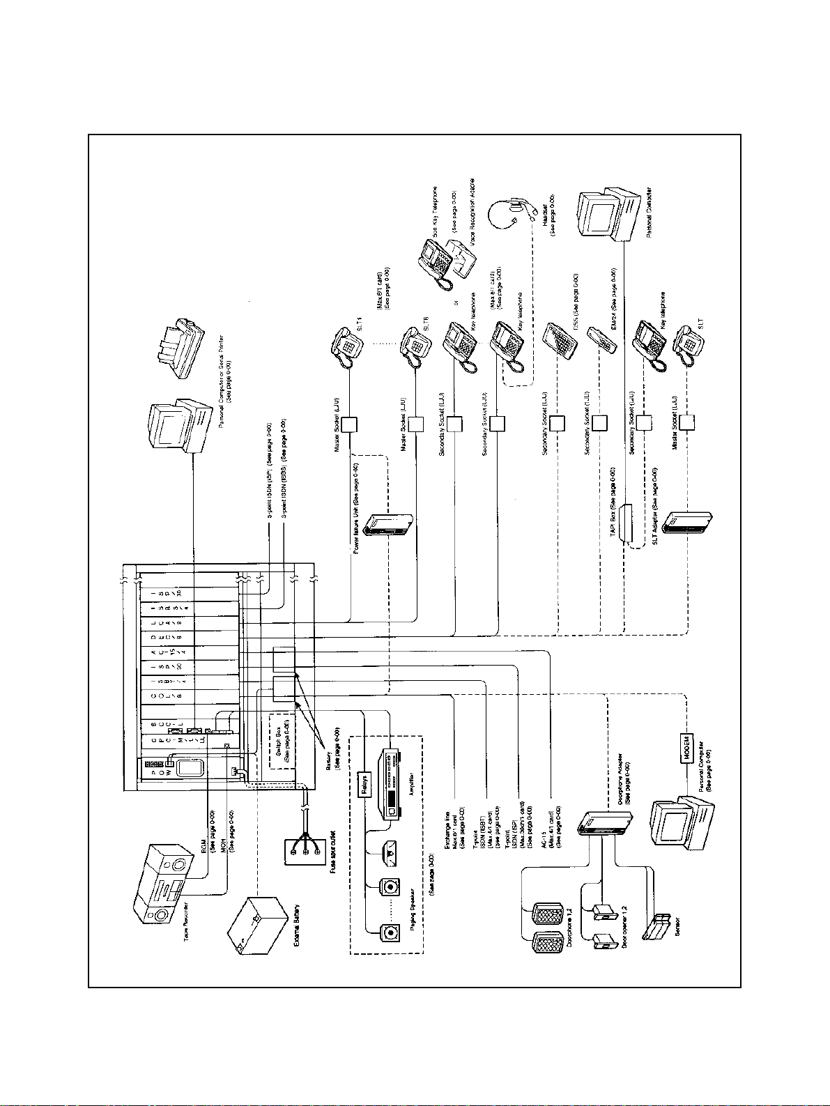
System Connections (trunks, extensions, peripheral equipment)
14 Chapter 2 - System Hardware
Page 19
CABINETS
g
(
y
y
y
)
)
y
g
(
g
y
CAB-40 Base Cabinet (VB-44010)
Each CAB-40 Base cabinet support s up to 4 0 ports usin
connection
CAB-40 + CAB 40) is available using connection cable kit.
flexible or universal c ard sl ots. Dual system
Multiple slot t
Slot type # of slots Unit type to be installed
Power slot 1 Accommodates the cabinet power supply. The power supply comes installed in
CPC slot 1 CPC in first Base cabinet (CPC-96);
Flexible slots 5 Accommodates trunk cards, extension cards, other cards (such as MFR), etc.
Option slots 2 The option slots support common con t rol cards (such as MFR, SCC, and TSW).
Optional backup batteries can be installed for s
pes are used in the CAB-40 Base cabinet. These slot types are as follows:
the cabinet.
stem operation in the event of a power failure.
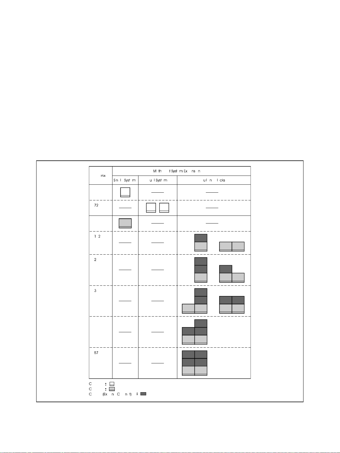
CAB-90 Base/Expansion Cabinet
Two t
pes are cabinets are used in the ICX:
1
the CAB-96
2)the CAB-96B
Each cabinet provides 96 universal ports. S
"buildin
-block" fashion. The bottom cabinet in a column is the
cabinets in a column must be
Base cabinet
(VB-44020
Expansion cabinet
Expansion
(VB-44021).
stems can be configured with one to six cabinets in a
Base
cabinet. The middle and top
cabinets.
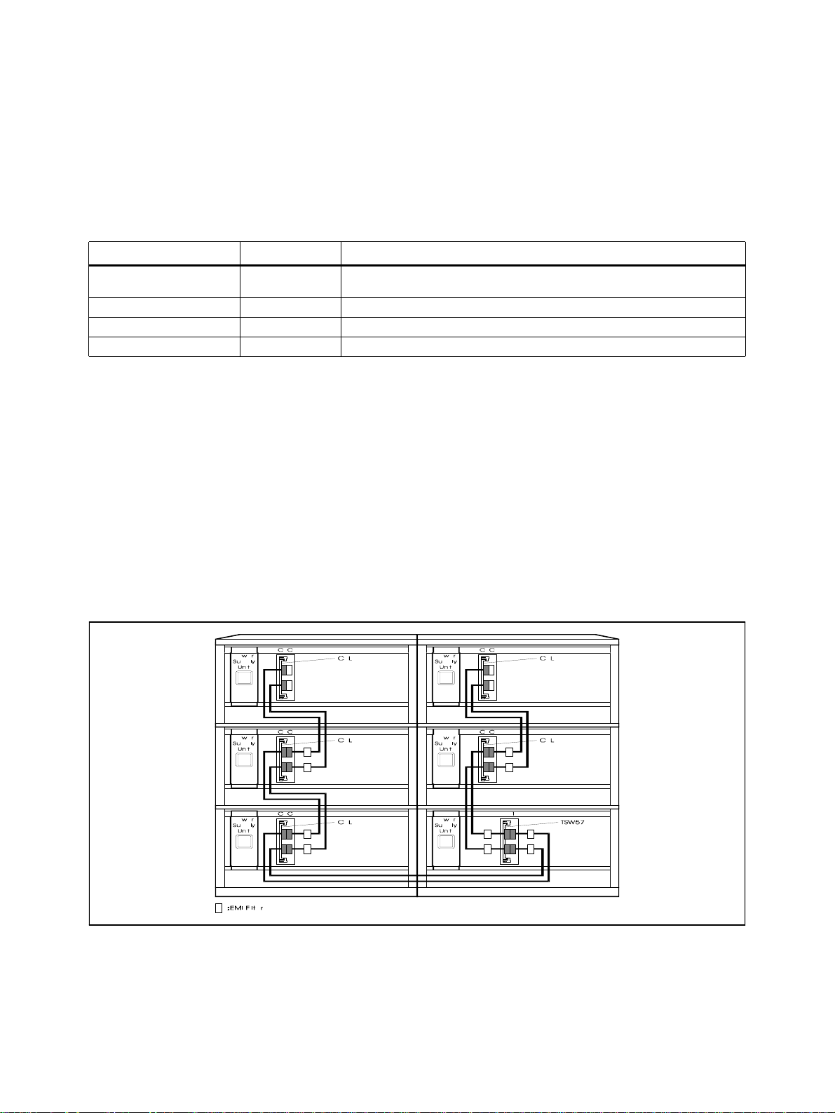
The maximum configuration for a fully expanded (6-cabinet) system supports a maximum of 576
ports, and contains two Base cabinets and four Expansion cabinets
see figure below).
Maximum 6-Cabinet Configuration
CAB-96 Base Cabinet (VB-44020)
Each CAB-96 Base cabinet supports up to 96 ports usin
CAB-96 Base cabinets can be installed in a s
stem.
flexible or universal card slots. Up to two
Chapter 2 - System Hardware 15
Page 20
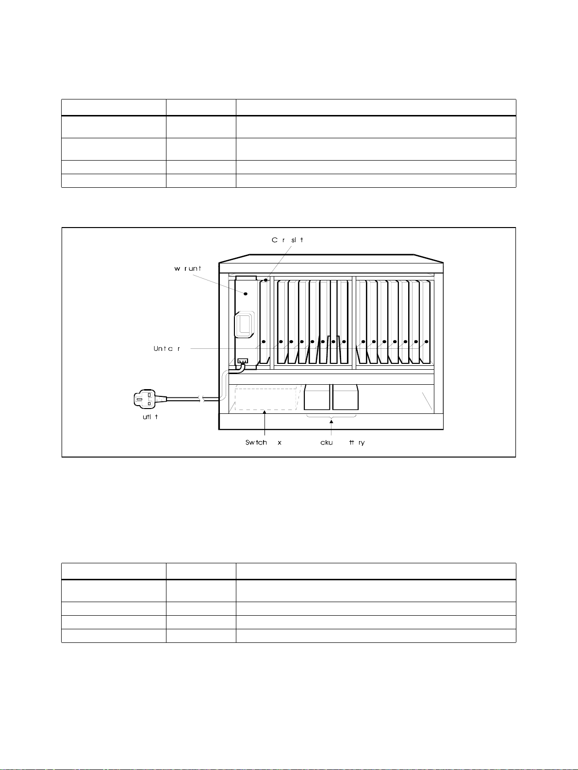
Multiple slot types are used in the CAB-96 Base cabinet. These slot types are as follows:
y
y
y eq
y
y
(
Slot type # of slots Unit type to be installed
Power slot 1 Accommodates the cabinet power supply. The power supply comes installed in
CPC slot 1 CPC in first Base cabinet (can be either CPC-96, CPC-288, or CPC-576);
Flexible slots 12 Accommodates trunk cards, extension cards, other cards (such as MFR), etc.
Option slots 2 The option slots support common con t rol cards (such as MFR, SCC, and TSW).
the cabinet.
expansion interconnection card) in second Base cabinet.
CBL
Optional backup batteries can be installed for s
stem operation in the event of a power failure.
The CAB-96 Base Cabinet
CAB-96B Expansion Cabinet (VB-44021)
Each added CAB-96B Expansion cabinet expands the s
stem capability by an additional 96 ports.
One or two CAB-96B Expansion cabinets can be installed on top of a CAB-96 Base cabinet. Up to
four CAB-96B’s can be installed in a full
uipped, 6-cabinet system.
Multiple slot t
pes are used in the CAB-96B Expansion cabinet. These slot types are as follows:
Slot type # of slots Unit type to be installed
Power slot 1 Accommodates the cabinet power supply. The power supply comes installed in
CPC slot 1 Accommodates the CBL (expansion interconnection) card.
Flexible slots 12 Accommodates trunk car d s , ex tension cards, and other cards (such as MFR).
Option slots 2 The option slots support common control car ds (such as MFR and SCC).
Optional back-up batteries can be installed for s
16 Chapter 2 - System Hardware
the cabinet.
stem operation in the event of a power failure.
Page 21

Fittings for Building Block Connection (VB-44024)
g
y
y
y
)
(s)
(s)
g
(
(
(
(
(
q
(
(
j
q
(
(
j
q
g
y
g
y
y
y
These fittin
normall
s are for interconnecting cabinets in the building-block configuration. The fittings are
shipped with the Expansion cabinets.
Battery Backup (VB-44025)
The backup batteries suppl
Backup option is chosen for the s
cabinet, 2 batteries per kit
power to the system in the event of a power failure. If the Battery
stem, each cabinet requires its own set of batteries (1 kit per
. The batteries can back up the system for up to 30 minutes.
Switch Box (VB-44023)
The Switch Box installs in the Base cabinet, and controls power for the Base cabinet and the
Expansion cabinet
cabinet, power is also turned on or off for the Expansion cabinet
installed above it. When the power supply is turned on or off in the Base
.
CONTROL UNIT
CPC-96 (VB-44410)
The CPC-96 supports a sin
le cabinet (40/ 96ports) and utilizes a 16-bit Central Processor Unit
CPU).
Included are the time switch
circuit
source
3 Member), service tones, DTMF generators, an input terminal for external holding tone
RCA jack), connecting terminals for network synchronous package, I/F connector for an
external PC card and a built-in modem
Since the time switch is built into the CPC-96 card, a separate time switch card is not re
4HW X 4HW), 4 MFR circuits (DTMF receivers), 8 pairs of conference
300 bps).
uired.
CPC-288 (VB-444201)
The CPC-288 supports up to three cabinets
Included are 4 MFR circuits
DTMF receivers), an input terminal for external hold tone source (RCA
288 ports) and utilizes a 16-bit CPU.
ack), I/F connector for an external PC card and a built-in modem (300bps).
The CPC-288 re
uires the TSW-288 Time Switch Card.
CPC-576 (VB-444301)
This unit supports up to six cabinets
It provides 4 circuits MFR
DTMF receivers), an input terminal for external hold tone source (RCA
576 ports) and utilizes a 32-bit CPU.
ack), an I/F connector for a customized PCMCIA memory card, and a built-in modem (300bps).
The CPC-576 re
Pro
ram downloads are performed to the internal memory of the system through the attached
customized PCMCIA card. The PCMCIA card is necessar
be removed durin
uires the TSW-576 Time Switch Card.
during normal operating time and cannot
normal operation.
Time Switch - TSW-288 (VB-444202)
The TSW-288 provides the time switch circuitr
with the CPC-288. This unit installs in the first option slot of the first Base cabinet. Onl
stem.
be installed in a s
required for up to 288 ports. This card must be used
Chapter 2 - System Hardware 17
one card can
Page 22
The TSW-288 provides the time switch (14HWx14HW), service tones, DTMF generator, connecting
y
y
y
y
(
y
terminals for network s
nchronizing unit interface, and 8 pairs of 3-party conference circuits.
Time Switch - TSW-576 (VB-444302)
The TSW-576 provides the time switch circuitr
with the CPC-576. This card installs in the first option slot of the first Bas e cabinet . Onl
be installed in a s
stem.
required for up to 576 ports. This card must be used
one card can
The TSW-576 provides the time switch
terminals for network s
Connection Cable Kit - CBL Kit (VB-44450)
nchronizing unit interface, and 8 pairs of 3-party conference circuits.
24HWx24HW), service tones, DTMF generator, connecting
This card supports the interconnection betwee n CAB40 and CAB40. T wo connection ca ble cords, one
for master cabinet, the other for slave cabinet and cables are packed.
Connecting CAB40 Dual system
18 Chapter 2 - System Hardware
Page 23
Building Block Expansion Cable Kit - CBL (VB-44451)
(
(s)
(
g
)
q
y
y
q
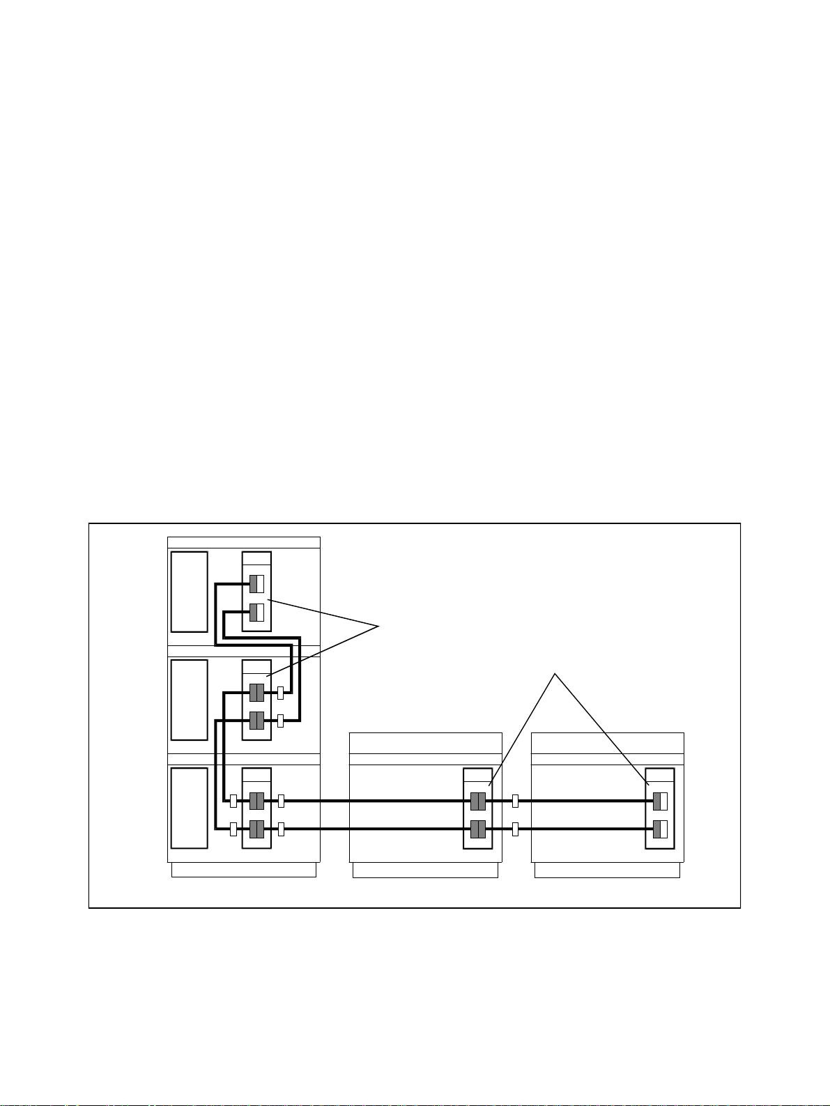
This card supports the interconnection between cabinets when multiple cabinets are used. This card
establishes the connection between PCM-HW bus and terminal control bus of the Base cabinet and
additional cabinets, as well as the connection to the time switch unit
TSW-288/TSW-576) in the first
Base cabinet.
Each cabinet after the first cabinet requires a CBL kit. The supplied card m ust be instal led in t he CPC
slots of all but the first cabinet. The supplied intercabinet connection cable is used with each added
cabinet.
ICX to DBS Expansion Cable Kit - CBLDBS (VB-44452)
The CBLDBS card supports the interconnecti on between cabine ts when DBS cabine ts are conne cted
to the ICX. This card establishes the connection of the PCM-HW bus and terminal control bus
between the base ICX cabinet and the DBS cabine t
, and also the connection to the time swit ch unit
TSW-288/TSW-576) installed in the first Base cabinet.
NOTE:
DBS cabinet. A maximum of two DBS cabinets can be included in the conf i
Extension Cards
is re
The ICX-to-DBS configuration can support a maximum of 528 ports, in clu ding the ports in the
uration. DBS DEC (Digital
are supported, but there is no DBS TRK (trunk) card support. A special MDF board
uired; it is included with the CBLDBS kit.
The CBLDBS card installs in the AUX1 slot of each connected DBS cabinet. An inter-cabinet
connection cable is used with each cabinet.
Connecting the ICX to a DBS system
Network Synchronizing Unit - SYNC (VB-44460)
This unit provides network s
SYNC card s
SYNC card is re
nchronizes the PCM clock with an outsi de resource. Wh en digital circuits are used, one
uired and installs on the CPC-96, TSW-288, or TSW-576 card.
nchronization and is required with digital circuits such as ISDN. The
Chapter 2 - System Hardware 19
Page 24

T RUNK LINE CARDS
y
g
(
y
q
g
g
(
g
(
g
g
g
(
g
g
Loop Start Card - LS (VB-44510)
The Loop Start Card supports up to 8 l oop sta rt CO li nes and can be instal led in an
card provides li
htning arresters and UL1459 safety circuitry, and can be directly connected to CO
flexible slot. This
lines.
Caller-ID Unit (CID)(VB-44513)
This card supports Caller ID on loop start trunks. This unit installs directly on top of the Loop Start
Trunk Card
VB-44510), and supports all 8 of that Card’s circuits for Caller ID.
Primary Rate Interface Card (T-point) - PRI (VB-44540)
T-point primar
card is also re
A li
htning arrester is built into the PRI card.
rate interface requires a DSU for connection to the carrier circuit. A Network Sync
uired.
Basic Rate Interface Card (T-point) - BRI (VB-44530)
This supports T-point Inte
rated Services Digital Network (ISDN) Basic Rate Interface (BRI)
2B+D:144 or 192kbps). This card can be installed in any flexible slot.
The functions supported are as follows:
Dial T ype
q
Information transferring capability
q
Enblock settin
and enblock setting at the sub-address.
speech and data) at the CO trunk.
The BRI T-Point connects throu
A li
htning arrester is built into the BRI card.
This supports T-point Inte
h a DSU to the T-point ISDN Basic Rate Interface.
rated Services Digital Network (ISDN) Primary Rate Interface (PRI)
23B+D/24B:1544kbps) (30B+D/31B:1984kbps) and also S-point ISDN Primary Rate Interface.
The PRI card can be set to support either 8, 16, 23/24 or 30 channels. When the card is set for 16
channels, the card logically occupies 2 flexible card slots. When the card is set for 23/24 or 30
channels, the card lo
ically occupies 3 or 4 flexible card slots.
Unlike other most other cards, due to the interaction between card slots, the PRI card must be
installed in selected flexible card slots. Up to 3 PRI cards can be installed in a single cabinet. A fully
ured 6-cabinet system can support up to 18 PRI cards.
confi
20 Chapter 2 - System Hardware
Page 25

E&M Trunk Card - E&M (VB-44560)
y
g
y
q
y (
y Ty
g
)
g
(
g
g
g
g
y
q
q
g
This card supports E&M t
si
naling methods that are supported include Immediate and Wink methods.
pe private line interface (Speech pass 4W/2W, Control line 4W). The
When installed in an
from other PBX or carrier e
flexible slot, the E&M Trunk Card supports call signal detection and answer
uipment, calling to the E&M private line, dial sending and speech.
Each E&M card includes 4 circuits.
An internal -48V Power Suppl
VB-44022) must be installed in the sam e cabi net with th e E&M Trunk
Card.
The E&M interface can connect to another PBX with E&M capability. However, this unit does not
support connection to an E&M that provides onl
This unit contains a built-in li
standard telecommunications suppliers
htning arrester; however, external safety devices (available from
are required when installing outside the building.
pe 1.
DID Trunk Card - DID (VB-44520)
This card supports 8 DID incomin
can be either Dial Pulse
10PPS) or DTMF (only for Wink). MFR circuits are used when the Wink
CO lines using Immediate and Wink signaling methods. The DID
method is selected.
An internal -48V Power Supply (VB-44022) must be installed in the sam e cabi net with th e E&M Trunk
Card.
A li
htning arrester is built into the DID TRK card.
T1 Trunk Card - T1 (VB-44550)
The T1 interface is a di
ital CO line card that prov ides up to 24 v oice c hannels over a four-wire ci rcuit.
The T1 card can be set to support either 8, 16, or 24 channels. When the card is set for 16 channels,
the card lo
ically occupies 3 flexible card slots.
lo
ically occupies 2 flexible card slots. When the card is set for 24 channels, the card
Unlike most other cards, due to the interaction between card slots, the T1 card must be installed in
selected flexible card slots. Up to 3 T1 cards can be installed in a single cabinet. A fully configured 6cabinet s
The T1 interface re
uired.
re
A li
stem can support up to 18 T1 cards.
uires a CSU for connection to the carrier circuit. A Network Sync card is also
htning arrester is built into the T1 card.
Chapter 2 - System Hardware 21
Page 26

EXTENSION CARDS
g
g
g
y
g
g
(s)
g
(
y
g
q
g
y
y
y
)
y
(
(
y
y
y
Digital Extension Card - DEC (VB-44610)
This card provides 8 di
le Line Telephone, DSS/72, and EM/24. Supply voltage for the telephones is supplied by the
Sin
di
ital circuits.
ital circuits. Each circuit supports the Pan asonic Digital Key Telephone, Digital
This card can be installed in an
flexible slot.
Analog Extension Unit (VB-44520)
This card provides 8 analo
analo
telephones, answering machines, fax machines, modems, cordless telephones, etc. The
connected device
A li
htning arrester is built into the analog circuits.
can be either pulse dial (rotary) or DTMF. Ringer circuitry is built into the card.
circuits. Each circuit supports standard analog telephone devices such as
BRI Unit (S-point) (VB-44630)
This unit supports Basic Rate Inte rfac e
2B+D:144 or 192kbps) for S-point ISDN. Each card provides
4 BRI circuits.
This card can be installed in any flexible slot.
The s
stem supplies +40V to the ISDN terminal which is connected to S-point interface card.
A li
htning arrester is built into the BRI circuits.
Primary Rate Interface Card (S-point)-PRI (VB-44540)
Same card as T-point.
OPTIONS
MFR Card (VB-44110)
The Multi-Fre
di
its. Each card contains 8 receiver circuits.
uency Receiver (MFR) card accepts dialled DTMF tones and determines the dialled
This card can be installed in either an option slot or an
installed in a cabinet, with up to 6 cards in a full
configured system.
flexible slot. A maximum of one card can be
8-Party Conference Card (VB-44120)
This card provides a set of 8 -part
conference circuit. (These are in addition to the 3-party conference
circuits built into the CPC-96, TSW-288 and TSW-576.
This card is installed in a flexi ble slo t. A maxim um of one c ard can be install ed in a ca binet, with u p to
6 cards in a full
configured system.
Built-In ACD Card (VB-44140)
This card, combined with the Voice Processor Unit card
Automatic Call Distribution functions. MIS
Management Information System) reports can be output
from the RS232C port of the ACD card. The reports can be printed out b
RS232C port. However, a PC and printer cannot be simultaneousl
RS232C cable must be used exclusivel
22 Chapter 2 - System Hardware
for one connection).
4 circuits) (VB-44160), provides simplified
connecting a printer to the
connected to the RS232C (the
Page 27

Only one Built-In ACD can be installed in a cabinet. A m aximum of two Bui lt-In ACDs can be installed
y
y
q
)
g
g
y
y
g
y
g
g
g
g
(any
g
y
y
y
g
g
g
g
y
y
y
y
(
g
y
in a s
stem.
Built-In V oi ce Mai l a nd Bu ilt-In ACD ca nnot be ins tall ed in t he s am e c abin et, sin ce the
flexible slots.
Built-In Voice Mail Voice Storage Card (VB-44170)
This is one of two cards re
44160 for 4 circuits; or VB-44150 for 8 circuits
The Voice Mail Voice Stora
hard disk stora
Onl
one Built-In Voice Mail can be installed in a single cabinet. A maximum of four Built-In Voice
e of the voice data.
Mails can be installed in a full
Don’t install the Voice Mail Unit from the top cabinet, otherwise the unit will be dama
uired for Built-In Voice Mail. One or two Voice Processing Cards (VB-
are also required for Built-In Voice Mail.
e Card provides most of the functions of Built-In Voice Mail, including
configured system.
ed by heat.
Built-In V oi ce Mai l a nd Bu ilt-In ACD ca nnot be ins tall ed in t he s am e c abin et, sin ce the
flexible slots.
Voice Processing Card (4 circuits) (VB-44160)
Two sizes of voice processin
processin
card contains four voice processing circuits and can be used with Built-In Voice Mail and
Built-In ACD. The other voice processin
voice processin
cards
Processin
circuits and can only be used with Built-In Voice Mail. One or two voice processing
combination of types) are required for Built-In Voice Mail. One VB-44160 four-port Voice
Card is required for ACD.
cards are available for use with the ICX. The VB-44160 voice
card, the VB-44150 Voice Processing Card, contains eight
use the same
use the same
Onl
one Built-In Voice Mail can be installed in a single cabinet. A maximum of four Built-In Voice
Mails can be installed in a s
same cabinet, since the
stem. Built-In Voice Mail and Built-In ACD cannot be installed in the
use the same flexible slots.
Voice Processing Card (8 circuits) (VB-44150)
Two sizes of voice processin
Processin
Card contains eight voice processing circuits and can only be used with Built-In Voice
Mail. The VB-44160 voice processin
with Built-In Voice Mail and Built-In ACD. One or two voice processin
pes) are required for Built-In Voice Mail.
t
Onl
one Built-In Voice Mail can be installed in a single cabinet. A maximum of four Built-In Voice
Mails can be installed in a s
same cabinet, since the
cards are available for use with the ICX. The VB-44150 Voice
card contains four voice processing circuits and can be used
cards (any combination of
stem. Built-In Voice Mail and Built-In ACD cannot be installed in the
use the same flexible slots.
SCC Unit (VB-44181)
The Service Circuit Card provides enhan ced se rvice fu nctions such as two RS232C ports
a Back
Onl
round Music input, and the external paging control.
one Service Circuit Card can be installed in a system.
!"#$
%&%''#' ' %##
('##'&''#') *##
#'#+ ,*!# -
9600bps),
Chapter 2 - System Hardware 23
Page 28

Power Failure Transfer Unit (VB-43703)
g
y
y
y
y
y
y
g
g
y
g
q
g
g
y
g
g
j
j
q
g
q
gg
g
g
g
g
g
g
y
The four-line power failure transfer is desi
compan
direct to a single line telephone when power is lost. The power failure transfer unit connects
four SLTs to four CO lines.
1 Line SLT Adaptor (VB-44100)
B
connecting the 1 line SLT Adaptor to the DEC/8 card, you can connect an SLT instead of an
extension ke
phone. One SLT can be connected to one 1 line SLT Adaptor unit.
STATION EQUIPMENT
Overview
The full line of Panasonic ICX phone s
All telephones work with all models of ICX s
ned to switch outside dial tone from the telephone
stems offer a wide variety of critically acclaimed telephones.
stems.
As the user interface, the station instrument is a crucial element of the communications s
ICX telephones are desi
fixed and pro
rammable feature keys allow the station to be specifically customized to accommodate
the needs of each user. A wide variet
pro
rammable keys, speakerphones, and liquid crystal displays to provide a complete solut ion to any
telecommunication re
evity of the ICX system and stations, protecting the investment of the end-user.
lon
All telephones are desi
q
Ke
lettering is a part of the key mold, making it impossible for lettering to
ned to provide easy access to system features and functions. A mixture of
of telephones are offered with different combinations of
uirement. The advanced economic design and quality manufactur ing assure
ned with the following features:
stem. All
fade or rub off.
q
Special film coatin
hting conditions.
li
q
Ad
ustable display contrast levels adapt to different lighting conditions.
q
ustable base for 3 different LCD viewing positions.
Ad
q
Photo optic controlled hookswitch, which extends the life of the
enables displays to be seen under extremely bright
hookswitch.
q
Uni
ue one-board design that allows for a more compact, durable product.
q
Special material separatin
li
uid spills.
q
Built-in processors provide aut omatic identi ficatio n when p lu
di
ital port, assuring instant operation.
q
Above-standard cords contain clamps to attach to the telephone’s base,
alleviatin
q
Hearin
q
Headset compatible.
q
Built-in wall mountin
q
Textured finish on selected hi
fin
q
Moulded with an extremel
stress on modular connectors.
-aide compatible.
erprinting.
the keys from the PCB reduces damage from
ed in at any
capability in the base of the telephone.
h-contact areas reduces scratching and
durable, high-impact polymaterial for break
resistance.
24 Chapter 2 - System Hardware
Page 29

q
y
y
g
)
(FF)
y
y
y
y
y
y
y
y
g
g
y
g
j
q
y
g
y
g
y
y
Telephone handsets allow eas
installation of handset cord swivels.
Model Options
Panasonic offers a wide variet
ht for you. All display phones come with a built-in sp eaker phone. Ha nds-Free Answerback (HFAB,
ri
described in detail in Chapter 4 - Stat ion Featu res
Line. Flexible Function
outside lines or execute s
of options for telephones so that you can select the one that is just
is standard on all phones e xcept the Digital Single
keys containing dual-coloured LEDs are user programmable to access
stem and station features. Listed below are some of the options available
with the different models:
• 12 ke
• 12 ke
• 12 ke
• 12 ke
• 24 ke
• EM24-24 ke
• DSS-72 Ke
• Di
UK, HK,
Indonesia,
Mala
sia:
-Speakerphone VB-44221
-Display Speakerphone VB-44223
-Large Display Speakerphone VB-44225
-Soft key Display Speakerphone VB-44224
-Display Speakerphone VB-44233
Expansion Module VB-44310
DSS/BLF VB-44320
ital Single Line telephone VB-41200
In addition to the above di
complete of the DBS proprietar
3011 Di
Taiwan: The former DBS proprietar
stems without modification. Please consult to your order.
s
MODEL DESCRIPTIONS
Digital Single Line Telephone (VB-41200)
Provides sin
include hold, on/off, Memor
conference. Lar
for volume ad
le line service on a digital telephone. Buttons
, redial, RECALL/FLASH and
e message waiting light. Slide controls
ustment. Does not support handsfree
answerback on intercom. Re
ital telephone module, the System supports the
VB-3411/3611 series telephones and VB-
ital SLT.
telephone are not available to connect to ICX
uires one digital port.
Chapter 2 - System Hardware 25
Page 30

12 Key Speakerphone (VB-44221)
ys (
y
q
ys (
y
q
y(
y
q
ys (
y
q
y(
y
q
y
g
ys (
q
y
y
g
g
y
g
q
Provides 12 flexible feature/line ke
and 10 personal speed dial ke
dual coloured LED)
s. Supports handsfree
speakerphone, off hook voice announce, and headsets.
uires one digital port. Wall-mountable.
Re
12 Key Display Speakerphone (VB-44223)
Provides 12 flexible feature/line ke
and 10 personal speed dial ke
handsfree speakerphone and 2 line li
displa
the displa
LCD). 4 programmable soft keys are included with
to provide access to advanced system
dual coloured LED)
s with an integrated
uid crystal
features. Supports handsfree answerback on interc om, off
hook voice announce, and headsets. Re
uires one digital
port. Wall-mountable.
12 Key Display Speakerphone with Voice Response - (VB-
44224)
Provides 12 flexible feature/line ke
and 10 personal speed dial ke
handsfree speakerphone and 2 line li
displa
the displa
LCD). 4 programmable softkeys are included with
to provide access to advanced system
dual coloured LED)
s with an integrated
uid crystal
features. Supports handsfree answerback on interc om, off
hook voice announce, and headsets. Re
port. Wall-mountable. Internal circuitr
Reco
nition feature.
uires one digital
for Voice
12 Key Large Screen Display Speakerphone- (VB-44225)
Provides 12 flexible feature/line ke
with a 7 line Li
of the displa
uid Crystal interactive display. The top line
contains 15 characters. The remaining 6
contain 16 characters per line. There are 10 softke
interact with the lar
screens can be assi
flexibilit
. This telephone comes equipped with a built-in
e screen display. User definable
ned to provide ultimate user-friendly
dual coloured LED)
s to
speakerphone for handsfree conversation on outside line
calls and a handsfree answerback circuit for respondin
to
intercom calls. This telephone also supports off hook
voice announce and headsets. Re
uires one digital port.
This telephone is wall-mountable.
26 Chapter 2 - System Hardware
Page 31

24 Key Display Speakerphone (VB-44233)
ys (
y
q
y(
q
(
)
q
g
q
(
y
y
q
g
q
g
(
g
g
(e.g
Provides 24 flexible feature/line ke
and 10 personal speed dial ke
handsfree speakerphone and 2 line li
displa
LCD). Supports handsfree answerback on
dual coloured LED)
s with an integrated
uid crystal
intercom, off hook voice announce, and headsets.
Re
uires one digital port. Wall-mountable.
24 Key Expansion Module (VB-44310)
Provides 24 flexible feature/line/Direct Station Selection
DSS)/Busy Lamp Field (BLF) keys (dual coloured
.This unit is used in conjunction with a digital station.
LED
Comes e
telephone to
Re
uipped with a joining bracket to connect it to the
ive the appearance of one complete unit.
uires one digital port. Wall-mountable. Includes
elevation supports.
72 Button DSS/BLF (VB-44320)
Provides 72 flexible feature/line/Direct Station Selection
DSS) Busy Lamp Field (BLF) keys (dual coloured LED).
Normall
positions, but can be used for an
e
attendant telephone to
complete unit. Re
used in conjunction with attendant console
extension port. Comes
uipped with a joining bracket to connect it to the
ive the appearance of one
uires one digital port. Wall-mountable.
Includes elevation supports.
OPTIONAL TERMINAL DEVICES
Voice Recognition Unit Adapter (VB-44101)
Workin
Speakerphone with Voice Response Telephone
functions to the telephone. The user can pro
in conjunction with the 12 key Display
VB-44224), this adapter adds voice response
ram the telephone to automatically dial numbers based
on the user’s voice commands.
PC Phone (VB-44332) (Future Feature)
The PC Phone is desi
ned to replace an extension phone, adding telephony capability to a desktop
PC. It is comprised of a PC card installed inside the computer; application software; and various
connections to the computer
., handset, headset, etc.). The PC Phone then plugs into a ICX
extension port, and becomes a sophisticated “on-screen” phone for the end-user. For more
information, see Chapter 5 - Special Applications.
Chapter 2 - System Hardware 27
Page 32

PC Attendant Console/96 (VB-44330) (Future Feature)
y
y
q
y
y
y
q
y
This is one of two PC Attendant Consoles offered b
replace an Attendant phone and add telephon
Console/96 is a 2-port solution that is e
phone, or a 12-ke
large-display phone) with one DSS/72; it can monitor up to 96 extension ports. For
uivalent to one key phone (either a 24-key small-display
Panasonic; both consoles are designed to
capability to a desktop PC. The PC Attendant
more information, see Chapter 5 - Special Applications.
PC Attendant Console/384 (VB-44331) (Future Feature)
This is one of two PC Attendant Consoles offered b
replace an Attendant phone and add telephon
Console/384 is a 6-port solution that is e
phone, or a 12-ke
large-display phone) with five DSS/72 consoles; it can monitor up to 384 extension
uivalent to one key phone (either a 24-key small-display
Panasonic; both consoles are designed to
capability to a desktop PC. The PC Attendant
ports. For more information, see Chapter 5 - Special Applications.
28 Chapter 2 - System Hardware
Page 33

TELEPHONE KEY LAYOUT
y
y
y
12-Key Small-Display Telephone key layout
Small-Display Telephone Features
No. Feature Description
1
Message Waiting Indicator Indicates that you have a message.
Displa
2
MODE Ke
3
END Ke
4
5
Soft Keys Used to select speed dial directories, or extension numbers.
Displays information about the phone’s status, menus, and dialling
directories.
Used to change display modes from Default Mode to Speed Dial
Mode or Extension Directory Mode.
Used to exit Directory Mode and return the display to Default Mode.
Chapter 2 - System Hardware 29
Page 34

y
y
y
y
y
y
y
y
y
y
No. Feature Description
PROG Ke
6
CONF Ke
7
8
One-Touch Keys Used to make outside calls or to access system features.
9
Flexible Function (FF) Keys Used to access outside lines or to access system features.
DND/CF Indicator Indicates that Do-Not-Disturb (DND) or Call Forwarding is set.
10
EXT Indicator Lights when you are on a call and flashes when you hold a call.
11
MIC Indicator Indicates that your microphone is activated. Lights solid when your
12
13
ON/OFF Indicator Lights when the
FL/R Ke
14
15
REDIAL Ke
16
MEMORY Ke
ON/OFF Ke
17
18
LINE Ke
VOLUME Ke
19
Used to program Flexible Function (FF) and one-touch keys, to adjust
ringer volume, and to send a flash signal. Depending on the setup of
our system, may also be used to transfer calls.
Used to establish conference calls and to check FF key and onetouch features.
hands-free microphone is activated.
ON/OFF
Used to end an outside call and to either restore outside dial tone or
switch to external dia l tone status without hanging up the receiver.
Used to redial the last number dialed.
Used to access speed dialing or enter account codes.
Used to make a call without lifting the handset or to turn the speaker
on and off.
Used to seize a free line from MCO outgoing group.
Used to adjust the level of tones, background music, ringing, receiver
volume, and display contrast.
key has been pressed.
HOLD Ke
20
Microphone Used to talk to another party without using the handset.
21
22
Speaker Outputs tones an d voice at your extension.
Used to hold calls, to retrieve held calls, and to complete FF key
programming.
30 Chapter 2 - System Hardware
Page 35

12-Key Large-Display Telephone key layout
y
y
y
(FF)
y
Large-Display Telephone Features
No. Feature Description
1
Message Waiting Indicator Indicates that you have a message.
Displa
2
Soft Keys Used to select menus, d irectories, speed dial numbe rs, and to a ccess
3
PROG Ke
4
CONF Ke
5
6
MIC Ke
Displays information about the phone’s status, menus, and dialing
directories.
call-handling features.
Used to program FF and one-touch keys, to adjust ringer volume and
to send a flash signal. Depending on the setup of your system, may
also be used to transfer calls.
Used to establish conference calls and to check Flexible Function
and one-touch key settings.
Used to turn on the microphone to answer bac k with hands-free.
Chapter 2 - System Hardware 31
Page 36

y
y
y
y
y
y
y
y
y
y
No. Feature Description
8
MENU Ke
7
8
PREV Ke
9
NEXT Ke
Flexible Function (FF) Keys Used to access outside lines or to access system features.
10
DND/CF Indicator Indicates that Do-Not-Disturb (DND) or Call Forwarding is set.
11
EXT Indicator Lights when you are on a call and flashes when you hold a call.
12
MIC Indicator Indicates that your microphone is activated. Lights solid when your
13
14
ON/OFF Indicator Lights when the
FL/R Ke
15
16
REDIAL Ke
17
MEMORY Ke
ON/OFF Ke
18
19
LINE Ke
Used to return to the default Main Menu screen which contains the
following items:
• Personal Dial
•System Dial
• Extension
• Function System
• Function Ext
Used to return to the previous screen.
Used to advance to the next screen.
hands-free microphone is activated.
ON/OFF
Used to end an outside call and to either restore outside dial tone or
switch to external dia l tone status without hanging up the receiver.
Used to redial the last number dialed.
Used to access speed dialing or enter account codes.
Used to make a call without lifting the handset or to turn the speaker
on and off.
Used to seize a free line from MCO outgoing group.
key has been pressed.
VOLUME Ke
20
HOLD Ke
21
Microphone Used to talk to another party without using the handset.
22
231
Speaker Outputs tones an d voice at your extension.
Used to adjust level of tones, background music, ringing, receiver
volume, and display contrast.
Used to hold calls, to retrieve held calls, and to complete FF key
programming.
32 Chapter 2 - System Hardware
Page 37

y
g
g
g
g
y
y
q
g
y
)
(
g
g
g
g
g
y
y
g
(
(
CHAPTER 3 - SYSTEM FEATURES
OVERVIEW
This chapter describes the numerous s
part of this chapter hi
hlights is a complete list of system features and the ICX versions to which they apply.
hi
POPULAR SYSTEM FEATURES
AUTO DAY/NIGHT MODE
Description:
The ICX system provides three different modes of operation. We call them Day 1, Day 2 and
Ni
ht mode. Each of these modes can have a different Attendant as well as different ringing
position assi
and out of an
special da
Benefits:
• Enables the system’s ringing and dialling capabilities to change automatically when
the mode is switched.
Applications:
• Lines that need to be switched over to an answering machine or Voice Mail system
after-hours
• Lines that re
lon
• Different mode for lunchtime operation
hlights the most popular features in alphabetical order. Following these
nments for extensions. The system can be programmed to automatically switch in
one of these modes at a preset time each day. Weekends, holidays, and other
s can also be programmed with their own separate modes.
uire toll restrictions after-hours so unauthorized personnel cannot dial
distance
stem-wide features that are available with the ICX. The first
AUTOMATIC ROUTE SELECTION (ARS)
This feature enables the s
cheapest one
denied based on the TRS level for the station
There are three levels of ARS, based on the number dialled after the ARS access code:
• Direct Route Selection.
di
• Route List Selection.
alternative levels of route selection, and includes a TRS check.
• Time List Selection.
appropriate route list based on the da
For “exceptions to the rule” such as holida
ramming with their own separate ARS routing methods.
pro
Itemized Codes
Codes
. Working in conjunction with Toll Restriction Service (TRS), the call can also be
roup and (if programmed) modifies the dialled number by deleting some of the first
its dialled, and/or adding digits to the beginning or end of the dialled number.
used when sending the calling extension’s number to the CO) and Authorization
used when sending a system identifier code to the CO) can be defined in ARS
stem to select the most appropriate route for an outgoing call (i.e., the
or user) placing the call.
The simplest form of ARS routin
A more complex routin
The most complex routin
and time.
s, up to 20 Special Days can be defined in
method that includes up to 5
method that determines the
. Directly selects the trunk
Chapter 3 - System Features 33
Page 38

programming, and entered as part of the digits automatically added to the beginning or end of
(
)
g
g
g
g
g
g
g
g
g sy
g
g
the dialled phone number.
The user won’t even know these Codes are being dialled.
Forced ARS (where the user must dial an ARS access code to be able to dial-out) can be
enabled/disabled via the Extension COS assi
Benefits:
nment.
• Lets the customer (management) control the routing of outgoing calls by defining the
route to be selected.
• Provides an effective means of cost control for expensive lon
• Provides
reater security, as end-users don’t need to know the Itemized Codes or
-distance calls.
Authorization Codes used to place calls to the CO.
CALL TRAFFIC REPORTING
Description:
Traf fic d ata ca n be s tored a nd prin ted for inte rcom c alls, incom ing trunk calls, and outgoing trunk
calls.
Benefits:
• Information can be used to evaluate CO line usage and control costs.
CALLER ID (CID)
Description:
Caller Identification (CID) is an optional service offered by your local telephone company which
adds the followin
functions to a display phone:
LCD indication of caller information.
q
while the incomin
h the D-channel.
throu
Log of caller information.
q
call is ringing their extension. This includes ISDN digital messaging
The Call Log keeps a record of the last 10 CID calls received at
an individual phone, and allows the user to view the Lo
Up to 20 phones per cabinet can have the Call Lo
SMDR recording.
q
CID information can be sent to the RS232C serial port so that it can be
printed to a serial printer or call accountin
CID notice to CTI.
q
CID information sent by the CO can be output to TAPI and other CTI
Users can see calling number information displayed
and select from it to place a call.
feature.
stem.
devices.
Benefits:
• Allows users to handle calls more efficiently by knowing who is calling before they
answer.
• Enables users to return calls that rin
unanswered at their phones.
CLASS OF SERVICE (COS) RESTRICTION
Description:
Specific feature restrictions can be placed on extensions or on trunks. There are up to 16
definable classes of service for extensions, and 16 more for trunks. If no COS is assi
features are allowed.
Benefits:
• Allows users to have telephones more customized to their needs.
ned, all
34 Chapter 3 - System Features
Page 39

Applications:
g
)
)
g
g
y
g
y
q
y
y
y
)
y
g
• Users with Single Line Telephones (SLTs) or those who need to limit access to
various features on selected telephones
COMPUTER TELEPHONY INTEGRATION (CTI)
Description:
For desktop computer-driven applic ations on a sta tion-to-st ation basis , the Pana sonic ICX of fers
powerful computer/phone inte
Console
as well as end-user phones (via our
rations for the Attendant position (via our
PC Phone
. For more information about these CTI
PC Attendant
applications, see Chapter 5 - Special Applications in this document.
Benefits:
• Enables customers to operate more efficiently by taking advantage of the latest
telephone and computer conver
a more intelli
Applications:
ent and streamlined way to do business.
ence. These industries are coming together to offer
• Control and pull up information on your “on-screen” phone based on caller
information
• Allows computer applications to control telephone operation
CONFERENCING
Description:
A user can conference up to three pa rties per conf erence or wit h additiona l hardware, u p to eight
parties per conference. Since the s
additional dB
ain/loss settings can be programmed for conference calls.
stem is digital, there is no internal dB loss. However,
The ICX offers two t
pes of conference calls. Wi th
2 outside lines per conference. With
8-party conferencing,
3-party conferencing,
one outside line and up to 7
there is a maximum of
extensions can conference-in.
Benefits:
• Enables users to create their own conference calls without the use of auxiliary
uipment.
e
• Saves time and mone
emplo
Applications:
ees/customers.
associated with conferencing geographically separated
• System accommodates up to eight simultaneous three party conference calls. (The
Bus
Override function can be used to set up conference calls.
DATA SECURITY
Description:
Data Security makes it possible to prevent interruptions on a phone. This feature is often used
when the phone is hooked up to a modem, but it could also be used for confidential or sensitive
calls. Data Securit
can be implemented for all phone usage, or it can apply only to outside line
use.
Benefits:
• Ensures confidentiality on important calls.
• Protects data transmissions from bein
Applications:
interrupted or cut off.
Chapter 3 - System Features 35
Page 40

• Modem phones
(
y
g
(
g
g
g
g
ging
g
g
y
• Sensitive accounts
i.e., lawyers, doctors, etc.) where confidentiality is important
DELAYED RINGING
Description:
An incoming or transferred call as well as intercom calls can be programmed to ring at a
secondar
specified len
positions
Benefits:
answering position if the call rings the primary answering position more than a
th of time. The call can be programmed to ring at one or more delay ringing
including phones with BLF keys).
• Ensures that a call does not go unanswered or ring for an extended period of time.
Applications:
• Any company that experiences short, temporary periods of high traffic and needs to
ensure that calls are answered
DIRECT INWARD SYSTEM ACCESS (DISA)
Description:
Any number of CO lines can be assigned to DISA lines which after being accessed, will enable
the incomin
entered, the caller will be able to access outside lines. Remote pro
over these lines after enterin
Benefits:
caller to dial any extension within the system. Or, if the proper security code is
ramming can also be done
a password.
• Allows internal personnel to access the system without tying up the attendant or o ther
lines comin
Applications:
into the system.
• Field sales people, repeat customers, etc.
DISTINCTIVE RINGING
Description:
Distinctive CO line ringing patterns can be set up for each extension, so the user can tell which
trunk is rin
. If no distinctive ringing is assigned, then the ringing pattern of the CO line will be
heard.
Benefits:
• Allows users to recognize the ring of their individual telephones or of the group of
telephones that are in their
Applications:
• Companies with separate departments or large, open bullpen areas
FLEXIBLE DIAL PLAN
Description:
The ICX’s dial plan is flexible. This means that the system comes with a default set of feature
codes, which can be chan
721. But
36 Chapter 3 - System Features
ou can change it to 7, or 2#, or ***, or anything else between 1 and 4 digits long.)
roup.
ed. (For example, the default Call Forward-All Calls feature code is
Page 41

It also means that you can have two different sets of feature codes for each system, dividing
g
g
g
)
y
g
ging
y
y
y
g
y
y
g
g
g
g
g
y
extensions into two differe nt
codes from di
Benefits:
ital extensions). Each extension can be assigned Dial Plan #1 or Dial Plan #2.
roups (for example, SL T pho nes can have a dif ferent set of feature
• Analog and digital phones can each have a unique set of feature codes.
Applications:
• When the ICX replaces another PBX system, the ICX feature codes can be
rammed to match the old PBX’s codes (one less thing for end-users to learn
pro
FLEXIBLE RINGING ASSIGNMENT
Description:
Ringing assignment is completely flexible so any CO line can be assigned to ring at any station
with a line-appearance ke
dependin
rin
Benefits:
on user requirements. In addition, Virtual keys can be used for second, third, etc.
positions on a single phone.
. This ringing assignment can differ in Day 1, Day 2, and Night modes
• Assures coverage for outside lines, increasing customer satisfaction.
• Allows for customization of the s
Applications:
stem in order to meet a wide v ari ety of applications.
• Any organization that is separated from main answering position
• Departments that continue operations after receptionist switches s
stem into Night
mode can continue to make and receive calls
“HOWLER” TONE
Description:
If any phone is unintentionally left off-hook, the phone will emit a “howler” tone so someone
will notice and hang it up. This feature can be enabled/disabled system-wide, and the
nearb
timer for it is also pro
Benefits:
rammable.
• Helps keep phones or trunk lines from bei ng inadvertently tied up because someone
didn’t put the handset back in the cradle.
HUNT GROUPS
Description:
Calls can be automatically transferred via one of 4 different automatic hunting modes. If a
telephone is bus
are bus
, the call is queued until one of the members becomes available. Or, if the call remains
unanswered, it is sent t o the nex t member afte r a pro
be sent to another
, the call hunts the next telephon e in the group. If all members of the hunt group
rammable period of time. The call can also
roup or extension after exceeding the hunt group overflow timer. This timer
can be set from 1 to 255 seconds; or the timer can be set to 0 so the call will not leave the
Up to 72 hunt
roups of 20 members each can be set up for each ICX system (maximum 12 hunt
roups per cabinet), with each hunt group having its own characteristics. If desired, Next
Extension / Hunt Group lets
ou specify which extension or Hunt Group search aft er the Queuing
Timer expired.
roup.
Chapter 3 - System Features 37
Page 42

Benefits:
g
g
g
g
g
y
g
g
g
(
(
g
(
y
g
ging
• Allows calls to hunt among a group of extensions designated as attendants, or
customer service
inte
Applications:
ration with Voice Mail or Automated Attendants.
roups where a group of people answer the same calls, or for
• Customer service departments, sales & marketi ng divisions, technical suppor t groups
MULTIPLE DIRECT INWARD DIAL (DID) ASSIGNMENT (FOR ISDN)
Description:
This feature allows a DID number to ring on more than one telephone through the use of virtual
ports. Also, one telephone can have multiple DID numbers assi
Benefits:
ned to it.
• Improves coverage of DID numbers and allows more flexibility in how an end-user
can pro
Applications:
ram the numbers.
• Executive suites, travel agencies, answering services
RECALL TIMERS
Description:
The ICX is equipped with various system-wide recall timers that help direct unanswered (maybe
otten) calls to someone who can answer them:
for
Start Recall from Hold -
q
extension, SLT, or Attendant that put it on hold. Each of these destination t
how long a call will remain on hold before recalling (ringing at) the
pes has its own
separate recall timer.
Start Recall from Transfer -
q
unanswered before it
the maximum amount of time a transferred call will rin
oes back (starts ringing at) the phone that made the transfer.
Attendants have their own Transfer Recall Timer, separate from extensions and SLTs.
Recall Duration -
q
how lon
a recall will ring before reverting to the default phone position
usually the Attendant).
Reversion Duration -
q
disconnected
Benefits:
how long a reverted call rings the Attendant Group before being
this can be set to “ring indefinitely”).
• Improves call handling efficiency and ensures that held/transferred calls will not be
lost or for
otten.
SLIDE RINGING
Description:
This is a type of delayed ringing for CO line FF-keys. Y ou can program a CO line to ring incoming
calls on certain phones first, then
that have a CO line FF-ke
appearance for that trunk. You can enable/disable this feature on
individual extensions and individual trunks. You can also set a timer for determinin
Rin
Benefits:
begins on the FF-keys.
if they remain unanswered) have them start ringing on phones
when Slide
• Provides delayed ringing for multiple line-appearance calls.
38 Chapter 3 - System Features
Page 43

STATION MESSAGE DETAIL RECORDING (SMDR)
g
g
g
g
g
g
g
g
g
g
]
g
g
Description:
By attaching a serial printer to the RS232C port, a detailed record of all incoming and outgoing
calls, can be kept for future reference.
Throu
accountin
The followin
h programming, the titles for each page can be removed to allow for connection to call
services.
is an explanation concerning the output format and display contents for call data:
Output Data Format
./
0&112222((((000++++++++++++++++++++++++33333
H
./
0&112222((((000++++++++++++++++++++++++++++++++++++++++3
3333########
H
1
Condition Code:
Incoming Calls Outgoing Calls
I
: Incomin
D
: DID.DDI incomin
h
: Hold incomin
N
: Network incomin
S
:DISA incomin
t
: Transfer incomin
call
call
call
call
call
call
F
: Call forward outside call
H
: Hold outgoing call
L
: LCR outgoing call
O
: Outgoing call [Non LCR
T
: Transfer outgoing call
W
: Network outgoing call
2
Call Start Time:
MM = 01 to 12 / DD = 01 to 31 / HH = 00 to 23 / MM = 00 to 59 / SS = 00 to 59
3
Call Duration Time:
HH = 00 to 23 / MM = 00 to 59 / SS = 00 to 59
4
Extension No.:
Extension No.: 0 to 9999
5
CO Line No.:
CO line No.: 1 to 576 / When CO line is disconnected while the call is on hold: *1 to *576
6
Dialled No.:
its max. including 0-9, *, and #. Cannot display Flash or Pause. If a number is hidden,
24 di
*
will appear instead of di
7
Accounting Code (Unverified):
10 di
its max.
its. * will stay with the call even if the call is transferred.
Chapter 3 - System Features 39
Page 44

y
y
y
y
y
g
g
y
y
)
g
g
g
)
y
g
)
g
y (
y
g
g
8
Accounting Code (Verified):
Verified ID code table number V001 to V400
9
Caller Data:
Format #2 onl
10
ISDN Charge Data:
Format #2 onl
H
Carriage return line feed
- originator number applies to ISDN onl
NOTE: Centrex and PBX codes, as well as ARS access codes, do not appear as dialled digits.
If the Caller ID Feature is installed and enabled, “Private” appears for calls with restricted Caller
ID displa
Benefits:
, and “Out of Area” for long-distance calls that do not provide Caller ID information.
• Provides accounting management tool for allocation of telephone expenses.
• Identifies areas for s
• Provides customer with record of telephone usa
etary and planning forecasts.
bud
• Prevents telephone abuse and misuse b
• Provides personnel evaluation tool to measure amount of emplo
stem or feature upgrade.
e which can be used in making
identifying unauthorized outgoing calls.
ee’s time spent on
the telephone.
Applications:
• Customers whose operation requires call tracking capabilities (e.g., lawyers,
consultants, etc.
SYSTEM SPEED DIALING (SSD)
Description:
The system can store anywhere from 80 to 800 SSD bin numbers that can be accessed by any
user. Selected users can pro
enabled for it in pro
di
its in length. End-users can “chain” up to 6 SSDs together inside a PSD (Personal Speed
bin, to handle phone numbers that are longer than 24 digits.
Dial
On a proprietar
pro
rammed Flexible Feature (FF) key, or by dealing “MEMORY” and the SSD bin number (0079 or 000-799
Index, showin
displa
or not display) the phone number being dialled when the user enters the SSD bin
ramming). The phone numbers stored inside the SSD bins can be up to 24
telephone, the SSD numbers would be accessed by either pressing a
. Or, on display phones, a user can select an SSD to dial by displaying an SSD
a list of current SSDs in the system. Individual phones can be programmed to
ram the SSDs on their extension phones (the phones can be
number to place the call. SSDs can be used to override toll restriction, if allowed in s
ramming.
pro
Benefits:
• Saves time and increases productivity by allowing the user to use abbreviated
dealin
Applications:
to access frequently called numbers.
• General business environment where many people call the same locations or
customers
stem
40 Chapter 3 - System Features
Page 45

TOLL RESTRICTION SERVICE (TRS)
y (
y
g
g
y
g
g
y
g
y
y
g
y
)
g
g
g
g
g
g
Description:
TRS lets you control user access to outside lines on a per-station and per-line basis. It can be
combined with ARS to block calls based on the number dialled, the outside line used, the
extension phone used, the tim e of d a
week/month/
q
A TRS Class can be assigned to each extension and trunk. Up t o 50 dif ferent TRS Classes a re
ear.
via Day, Night and Night 2 modes), and/or the day of the
available.
q
Each TRS Class is then assi
allowin
q
There are 10 TRS Levels available. Level 0 denies all calls. Levels 1-8 can be partiall
restrictive per assi
q
TRS can restrict the number of digits dialled (1-20 digits, or no limit).
q
TRS can restrict the use of SSDs for outdialing, based on TRS Class assignments. Either all
SSDs or a ran
q
TRS can also restrict the dialling of * and #, again based on TRS Class assignments.
q
The same phone can have different TRS restrictions during Day and Night modes.
Benefits:
/restricting calls.
nments. Level 9 allows all calls.
e of them can be restricted.
ned to a TRS Level. It is this Level that is used as the basis for
• Controls toll calling expenses by allowing the customer to define an individual
station’s capabilit
• Prevents toll callin
to use outside CO line groups.
abuse by providing automatic blocking of calls placed to
restricted phone numbers.
Applications:
• Cost-conscious customers who wish to control telephone expenses
WALKING TRS
Description:
A user can use his or her calling privileges at another extension by entering a 4-digit (0-9) ID
code. This enables the other extens ion to temporaril
defined b
the Toll Restriction Service (TRS) data of the user’s extension. When the user hangs
up the telephone, the extension returns to its ori
call from a telephone that is normall
restricted, such as a warehouse phone or lobby phone.
have CO line access capabiliti es which are
inal TRS type. (This allows a user to make a
NOTE: The Walking TRS code must be programmed at the user’s extension before it can be
entered at a different extension. The same code can be pro
The entered Walkin
Walkin
TRS code; nnnn is the 4-digit code).
Since a phone can have a different TRS Cla ss assi
the Walkin
TRS codes will follow these assignments. So, for example, long-distance calls can
be allowed on the phone durin
Benefits:
TRS code will show up on the SMDR report as: “Wnnnn” (W means
nment during Day, Night and Night 2 modes,
the day, but restricted at night.
rammed on multiple extensions.
• Allows a telephone to be restricted, but still allows certain users to override the
restriction.
Chapter 3 - System Features 41
Page 46

Applications:
y
)
)
y
g
)
)
y
)
)
)
y
y
g
)
)
)
g
y
• Warehouse telephones, waiting area, etc.Warehouse telephones, waiting area, etc.
LIST OF AVAILABLE SYSTEM FEATURES
System Features
Features Notes
Alarm Ringing for Unanswered Calls
Alarm Tone for Lengthy CO Calls
Analog Device Compatibilit
Attendant Group not applicable on Single Line Telephones (SLTs
Auto Day/Night Mode
Automatic Route Selection (ARS
Automatic Trunk-to-Trunk Transfer
Background Music (BGM) / Music-on-Hold Separation
Battery Backup
Behind PBX/Centrex Compatibilit
BLF Ringin
Building Block (up to 6 cabinets
Built-In 2-Way Voice Mail
Built-In ACD
Call Progress Tones
Caller ID (for ISDN
Class of Service (COS) - CO/TIE Feature
Class of Service (COS) - EXT-EXT Restriction
Class of Service (COS) - Extension Feature
Class of Service (COS) - TRK-TRK Restriction
CO Trunk Interface (ISDN BRI
CO Trunk Interface (ISDN PRI
CO Trunk Interface (Loop Start
Computer Telephony Integration (CTI) Capabilit
Data Securit
Delayed Rin
Delayed Ring - Day/Night Modes
Digital Pad Settings for Automatic Volume Adjustment
Direct Inward System Access (DISA
Distinctive Ringing for Incoming CO Line Calls not applicable on Single Line Telephones (SLTs
Door Box Connection (CO Connection
Door Opener
Flexible Numberin
Flexible Station Functions available on large-display phones onl
Free Slot
Hot Line
Howler Tone for Lengthy Off-Hook/Dial Tone
Hunt Group Pilot Number
available on display phones onl
1-4 digits in Extension Nos.
changeable Feature Access Codes
42 Chapter 3 - System Features
Page 47

)
g
g
)
g
y
g
)
g
)
y
g
y
y
)
)
Features Notes
Hunt Groups - Circular
Hunt Groups - Pilot Distributed
Hunt Groups - Pilot Terminal
Hunt Groups - Switch Back
Integrated Services Digital Network (ISDN)/BRI S-Point
Interface
Integrated Services Digital Network (ISDN)/PRI S-Point
Interface
Maintenance (local and remote
MCO Tenant Group
Memory Backup
Multiple Ringin
Music-On-Hold - Internal
Music-On-Hold - External
Non-blocking Architecture
Page Zones - External up to 5 External page zones per system
Page Zones - Internal up to 10 Internal page zones per system
PC Based Programmin
Port/Channel Close
Power Fail Transfer
Power On Maintenance (Extension/Trunk
Program Data Output
Recall Timers
Slide Ringin
Soft Key Operation available on display phones onl
Speed Diallin
Station Message Detail Recording (SMDR
Station Name Assignment
System Fault Recordin
System Speed Dial (SSD
System Speed Dial (SSD) Name Assignment available on display phones onl
System Speed Dial (SSD) Toll Restriction Override
Telephone Programmin
Toll Restriction
Traffic Measurement
Trunk Group
Trunk Name Assignment available on display phones onl
Virtual Port (Floating Park
Virtual Port (Virtual Extension
Voice Mail Integration
Voice Recognition requires Adapter Kit for each phone
up to 800 SSDs per system
available on display phones onl
Chapter 3 - System Features 43
Page 48

44 Chapter 3 - System Features
Page 49

g
y
g
y
y
g
(
y
(
)
g
g
g
(
y
g
y
(
g
g
y
y
CHAPTER 4 - STATION FEATURES
OVERVIEW
soft keyssoft keysICXThis chapter describes the many features that end-users can perform on ICX
station phones. Some of the most popular functions are hi
Features is included at the end of this chapter.
POPULAR STATION FEATURES
ACCOUNT CODE CAPABILITY
Description:
This feature works with Station Message Detail Recording (SMDR). During a phone call, a
station user can silentl
on the phone’s LCD as it’ s dialled, so the us er can tell it’ s bein
reports will show the Code dialled for each call, and even sort the report b
enter an accounting or client billing code. The entered Code will display
hlighted below. A complete list of Station
registered. Then later , the SMDR
these Codes.
There are two different t
Non-Verified Account Codes
Non-Verified Codes aren’t checked by the system for validity; the user can enter anything
from 1-10 di
the user must enter a code for every call) or
code, but doesn’t have to, for each call
Non-Verifi ed Account Codes can be ass i
calls, the user can enter the Code one-time durin
enters the Code before accessin
call
for
Verified Account Codes
Verified Account Codes entered by phone users must match a 4-digit code that has been
prepro
Verified Account Code; however, onl
codes can also be either
Restriction Service
extension’s TRS Class. Thus, Verified Account Code users can “float” from phone to phone,
placin
Benefits:
• Provides a way to allocate telephone expenses (outgoing calls) to specific clients/
departments as a cost accountin
• Doesn’t limit the expense allocation b
phone
• Displays the entered Account Code on the phone’s LCD, al lowing the user to verify it
immediatel
its long. Individual phones can be programmed to accept
voluntar
rammed into an Account Code Table. (It is possible to enter up to 10 digits for a
calls that would normally be restricted on that phone.
users,
pes of account codes you can use in the ICX:
Account Codes
forced
voluntar
.
ned to incoming and/or outgoing calls. For incoming
an outside line (for
Codes).
the first 4 digits will be used to verify the code.) These
or
forced
TRS) Class assignment so that, when entered, they will override the
not to the
.
voluntary.
phones.
You can program these codes with their own Toll
tool.
phone; the Account Codes are specific to the
Account Codes
the call. For outgoing calls, the user either
Codes), or one-time during the
forced
the user can enter a
Chapter 4 - Station Features 45
Page 50

• Provides record-keeping confidentiality by allowing the user to enter the Account
g
y
y
g
g
y
g
g
g
g
y
g
g
y
Code while the call is in pro
an
Applications:
other indication to the outside party.
ress, without interrupting the conversation or showing
• Customers who need to track outgoing calls so they can bill clients such as lawyers,
accountants, etc.
• Customers who allocate phone call expenses b
project
ALARM RINGING
Description:
If an incoming trunk call rings unanswered for a (programmable) period of time, the call’ s ringing
pattern and dB level chan
lon
er. You can program the pattern and level of the ringing. You can also enable this feature on
es automatically so users can tell which calls have been ringing
some trunks, and disable it on others.
Benefits:
• Users can distinguish between calls that have been ringing longer than others.
Applications:
• Noisy office environments; heavy call traffic
ALARM TONE FOR LENGTHY CALLS
Description:
If a user is on a phone call for a long time, an alarm tone sounds intermittently in the handset
receiver . This feature can be turned on /off s
also enable/disable individual phones and trunks for it, as well as pro
time before the alarm
Benefits:
oes off.
stem-wide in programming. If you turn it on, you can
ramming the amount of
• The ICX can automatically monitor call duration, and let users know when they’ve
been on a phone call too lon
.
ATTENDANT CALLING
Description:
With this feature, multiple phones can serve as Attendant consoles v ia a programmed Attendant
Hunt Group. When a phone user dials “0” to reach an operator , the firs t Attendant member phone
in the Hunt Group rin
member; and so on. Or
Up to 20 extensions can be members of the Attendant Hunt Group. You can pro
Attendant Hunt Group to rin
member’s actual extension number, the call won’t enter the Hunt Group.
Benefits:
• The Attendant position isn’t limited to just one phone. Different phones can act as the
s
stem operator position, depending on the time of day.
• Other phones can serve as backup positions for the Attendant phone.
46 Chapter 4 - Station Features
s. If it continues to ring unanswered, the call goes to the next Attendant
ou can program some of the members to ring simultaneously.
ram a different
during Day1, Day2, and Night mode. If someone dials the
Page 51

AUTO-REPEAT DIALLING
y
y
g
g
g
g
(
)
(
y
g
g
y
g
g
y
g
y
y
Description:
If a user places an outside phone call and gets a busy tone, he/she can stay on the line and
press REDIAL. The ICX will automaticall
to detect bus
rammable intervals) until the called party answers, the user hangs up, or 14 more redials are
pro
or answer while the user is waiting. If it’s still busy, the system will try again (at
hang up, reseize the trunk line, redial the call, and wait
attempted.
You can turn this feature on/off for individual extensions, and also enable/disable it on individual
trunks. You can also pro
ram the amount of time the system waits to detect busy or answer, as
well as the interval between redial attempts.
Benefits:
• An automatic feature that helps phone users save time and reduce dialling errors.
BACKGROUND MUSIC (BGM)
Description:
Users can set their phones to play Background Music on-speaker while the phone is idle. If the
phone receives a call, or the user
ain. BGM can be turned off by dialling the same code that turned it on. BGM can have a
a
different sound source than Musi c-On-Hold
Applications:
oes off-hook, BGM wi ll go away until the phone becomes idl e
MOH) (what callers hear when they get put on hold).
• One sound source for employees (BGM, typically music), another for callers (MOH,
such as recorded advertisements
.
BUSY OVERRIDE (“BARGE-IN”)
Description:
An extension user can barge into a call on another extension, whether it’s an outside or intercom
call. Phones set to Do-Not-Disturb
DND) can also be barged into; see
DO NOT DISTURB
more information.
When a barge-in occurs, a 3-party conference call is created; all three parties can hear each
other and talk to each other. There are two wa
Extension Busy Override,
q
code to bar
CO Key Busy Override,
q
e-in.
represents the call in pro
You can pro
ram the ICX to send an alert tone to all parties when the barge-in occurs. You can
also allow/block the phone’ s abil it
assi
nment (see
Benefits:
CLASS OF SERVICE
where the user dials the extension,
where the user presses the lit CO line ke
ress.
to perform this feature based on the phone’ s Cla ss of Service
for more information).
s to barge-in on a call:
ets busy tone, and dials a
on his/her phone that
• Allows operators, secretaries, bosses, etc. to interrupt calls in progress with urgent
information or other calls that need to be answered.
• Provides a wa
, or between three users.
part
to establish a 3-party conference between two users and an outside
for
Chapter 4 - Station Features 47
Page 52

CALL DURATION DISPLAY
y
)
g
y g
)
ge g
g
g
ging; y
g
(phy
g
g
y
y
Description:
The length of a call in progress (minutes and seconds) is tracked and displayed on the phone’s
LCD.
Benefits:
• Users can tell how long they’ve been on a call -- and what the SMDR report is going
to show for that call.
CALL FORWARDING
Description:
Call Forwarding allows users to automatically send their calls to another extension, to an outside
line, or to Voice Mail. There are several different t
chart below
. All types can be set or canceled manually by the phone user. The user can also
clear the phone of all of its Call Forward and DND settin
telephone is in DND, a call can be transferred to it; the call will automaticall
Forward destination.
Users can also set/clear Call Forward settings on other extensions from
pes of call forwarding to choose from (see
s with a single code. (Even if a
o to the Call-
their own phones.
Call Forwarding Types
Call Types to be Forwarded
All Calls
Bus
No Answer
Busy/No Answer
External Calls Onl
Benefits:
• Provides a way to pick up calls for absent personnel who are not part of a call
covera
• Allows for inte
Applications:
roup.
ration of Voice Mail systems.
• Sales, marketing, customer service, etc.
• Companies usin
Automated Attendant and/or Voice Mail
CALL PARK
Description:
This feature is often used with Paging. It’s a type of transfer that doesn’t involve the phone
rin
Virtual Call Park.
q
pa
ou simply “move” the call to another location. There are two types of Call Park:
e the person to pick up the call from any extension by dialling a Park Pickup code and the
orbit number.
Station Call Park.
q
wants to walk over to another desk and conduct the call from there.
If the parked call isn’t picked up, a pro
ori
inal extension.
48 Chapter 4 - Station Features
Also known as Park Orbit. Users can park the call to a Virtual extension, and
The call can be parked onto another
sical) extension, when the user
rammable timer determines when it will return to the
Page 53

Benefits:
y
g
y
y
g
y
g
y
y
g
y
y
g
q
g
ging
(
g
g
y
• Better call handling capabilities.
• When a part
e the party to pick up the call.
pa
cannot be reached at his/her phone, a user can “park” the call and
CALL PICK-UP
Description:
Phone users can pick up calls ringing on another (single) extension, other (multiple-ringing)
extensions, in an Extension Group, on a specific trunk, or in an MCO Trunk Group. Almost an
pe of call can be picked up, including DID/DISA calls, network calls, and voice intercom calls.
t
Benefits:
• Allows phone users to pick up calls, no matter where they’re ringing, without leaving
their workstations.
Applications:
• Customers who need call coverage for unattended stations
• Or
• Customers who presentl
anizations with department structure
have a key system operating behind a PABX to provide
roup pick-up capabilit
CALLBACK REQUEST
Description:
A phone can alert its master (the user) when another, busy extension becomes free. Say
Extension “A” calls Extension “B” who is bus
and concentrate on other thin
s. When “B” becomes free, “A” will ring. When the “A” user picks
up the handset, the “A” phone will automaticall
Benefits:
. “A” can dial a Callback Request code, hang up,
ring the “B” phone.
• The user doesn’t have to keep redialing a busy extension. The phone does all the
work.
CALLER ID CALL LOG
Description:
The Call Log keeps a record of Caller ID calls to individual phones. The Call Log allow you to
view Caller ID calls that have been sent to
extension can use this feature. Max. 10 lo
our phone and, if desired, return or call. per CCU, 20
s per extension.
CAMP-ON (CALL WAITING)
Description:
You can program phones to be able to “camp-on” calls to other extensions. This in effect
ueues” the call onto a busy extension. On phones that are programmed for
“
On
, put the call on hold, dial the extension to transfer the call to, and han
Camp-On
splash tone in the receiver, and/or a confirmation tone on-speaker
off in pro
To pick up a camped-on call, either han
put the current call on hold. You’ll be automaticall
, users dial a Camp-On code before han
ramming).
up from the current call and then go off-hook again, or
up.) The busy extension will receive a
both tones can be turned on/
connected to the caller.
Chapter 4 - Station Features 49
Automatic Camp-
up. (For
Manual
Page 54

Benefits:
g
g
q
g
g
y
g
y
g
g
g
)
g
• Users only have to call a busy extension once. They don’t have to wait for the station
to become free, or interrupt the current call, to transfer a waitin
Applications:
• Any user who wants to be notified of another call, without the current caller being
aware of it
• Attendants who don’t have time to wait for extensions to become free before
transferrin
calls to them
CONFERENCE CALLS
Description:
Users can include other parties in an existing call. The ICX offers
can consist of:
q
1 extension + 2 CO lines
q
2 extensions + 1 CO line
q
3 extensions.
There’s also
This re
Applications:
8-Party Conferencing
with 1 CO line and up to 7 extensions , or up t o 8 exten sions.
uires an extra Conference Card (VB-44120) installed in the ICX cabinet.
• Employees in separate buildings who want to hold meetings over the phone
• Telemarketin
applications where a stati on use r ne eds to co nference-i n a Sup erviso r
for assistance
call to it.
3-Party Conferencing
which
DO-NOT-DISTURB (DND)
Description:
DND enables station users to stop all transferred intercom and CO calls from ringing their
station, but still be able to make out
distinctive bus
DND settin
Benefits:
signal. But individual phones can be programmed with the ability to override
s on other phones.
oing calls. Anyone who calls the DND station will hear a
• Enables a user to quickly and easily initiate privacy for important meetings, etc.
DP-TO-DTMF SIGNAL CONVERSION
Description:
While on a DP (dial pulse) trunk, a user can switch to DTMF (dual tone multi-frequency) signaling
pressing the Q or # key. DTMF signaling is required whenever additional digits are dialled after
b
connectin
You can pro
out
Benefits:
to an automated answering system such as Voice Mail, Auto Attendant, etc.
ram the ICX to automatically change DP to DTMF tones based on incoming and
oing timer programming.
• Users can send DTMF signal to the other party (such as a bank computer or Voice
to specify service numbers.
Mail
Applications:
• Users dialling into a V oic e Mail or Auto-Atten dant system on a DP trunk. They’ll need
to switch to DTMF si
naling to select Voice Mail options by dialing numbers on the
50 Chapter 4 - Station Features
Page 55

phone when prompted. (for example, they’ll hear:
g
)
g
y
y
(
(
g
y
g
y
g
g
y by
g
g
(
y
g
Purchasin
, press 2.”
“To reach Sales, press 1. To reach
DSS/BLF KEYS
Description:
With the Direct Station Select/Busy Lamp Field feature, a phone’s FF-k ey can be programmed to
represent another extension. The phone user can perform the followin
Monitor the extension’s current status.
q
represents is currentl
Or, it’ll be blank
Call the extension.
q
to the extension. No pressin
press the DSS/BLF ke
Pick up the extension’s calls.
q
immediatel
Delay-ring the extension’s calls to your phone.
q
phone will rin
connect to the caller.
for the extension’s unanswere d calls. Press the flashi ng DSS/BLF key to answer
busy. It’ll flash when there’s an incoming call ringing to that extension.
unlit) while the extension is idle.
Just press the
Hold, no dialing the extension number, no transfer codes. Just
. It’s that simple.
A
The DSS/BLF ke
will be lit red when the extension it
unlit) DSS/BLF key to ring the extension. Or, transfer a call
ain, just press the DSS/BLF key while it’s flashing. You’ll
After a pro
rammable period of time, your
using DSS/BLF keys:
the call.
Benefits:
• Users can monitor calls to other extensions, and answer them if no one else does.
• Users can transfer calls to an extension simpl
Applications:
pressing the DSS/BLF key for it.
• Receptionists, secretaries, o perators -- anyone who needs a quick and simple way to
et calls to, and receive them from, other extensions
DUAL-COLOR LEDS
Description:
Each LED key has dual colors underneath. Red is a busy CO line and green is the CO line you
are speakin
Benefits:
on. These dual colors are utilized to indicate busy or DND stations.
• Lets users know what CO line they’re talking on, especially when they put the call on
hold.
• Helps users monitor the status of stations
Applications:
if the key is being used as a DSS/BLF).
• Systems that are designed as “squared,” and multiple lines appear on telephones
• Boss/secretar
applications
FLEXIBLE FEATURE KEYS (“FF-KEYS”)
Description:
Every FF-key on a telephone can be programmed by the end-user for a variety of one-touch
features. The followin
4 !##+ 4 '#- 4 2+%&%'' 4 5-4 ! 4 10%&%'' 4 6#- 4 5+%7!##
4 !89 4 1#!-%7 4 7-7 4 89
4 -:6 4 1#5#$ 4 :! 4 +14 4 1(1 4 -:;-+ 4 7#$
is a list of some of those features:
Chapter 4 - Station Features 51
Page 56

y
g
g
y
g
y
y
(
g
y
y
y
y
gg
)
y
4 .+- 4 1&7. 4 89 4 # <#4 5#$ 4 (- 0' 4 <#!##
Benefits:
• Flexibility to custom-configure a telephone to suit the individual user’s needs.
• Eas
one-touch feature access, instead of having to remember (and dial) codes.
HANDS-FREE ANSWERBACK
Description:
Station users receiving an intercom call can answer a Voice call on-speaker, without picking up
the handset or otherwise touchin
via the Extension COS (Class of Service) assignment in programming. Extensions can
callin
also be individuall
the Extension COS assi
b
dialing “1”. A “splash” tone alerting the called party of the on-speaker condition can be
enabled/disabled s
Benefits:
enabled or disabled for Send Voice Calls and Receive V oice Calls (again, via
nment). If a user begins a Tone call, he/she can switch to Voice calling
stem-wide.
the phone. Individual phones can be initially set for Voice
• Users can answer intercom calls without touching the phone.
HEADSET CAPABILITY
Description:
A proprietary phone’s FF-key can be programmed for activating/deactivating Headset Mode on
the phone. When it’s activated , all audi o
including the speaker) is switched to the Headset jack,
and the “RELEASE” and “ANSWER” buttons replace handset on/off-hook functions.
Benefits:
• Increases user efficiency by allowing headset operation from any proprietary
telephone, eliminatin
Applications:
the need to lift or hang up the handset.
• Attendant position, customer service, etc.
HOLD
Description:
With its Call Holding features, the ICX lets you control who can pick up a call on hold:
System Hold:
q
Exclusive Hold:
q
Floating Hold:
q
, and any phone with that key (set according to a programmable dial plan) can pick up the
ke
An
Onl
A kind of S
call.
Brokers Hold:
q
other is on hold
Benefits:
A user can to
.
• You can limit the number of people who can pick up a call on hold.
• You can allow an
•
•
•
52 Chapter 4 - Station Features
one can retrieve the held call from their own phone.
the person who put the call on hold can retrieve it.
stem Park where the user can transfer the call to a Floating Hold
le between two calls by pressing HOLD (one call is current, the
one to be able to pick it up, no matter where it’s put on hold.
Page 57

HOT DIAL PAD
y
y
g
g
g
)
g
y
)
)
y
)
)
(
y
Description:
A user can simply walk up to a digital phone and start dialing without picking up the headset. The
call immediatel
course, the user can pick up the hadset an
switches to the phone’s speaker, and the entire call can be conducted on it. Of
time to take the call off-speaker.
This feature can be enabled/disabled on individual extensions in pro
limitation on the number of di
phone is idle, has another call on hold, or is receivin
Benefits:
ital phones that can have Hot Dial Pad. It’ll work whenever the
a page.
raming. There is no
• Calls can be initiated hands-free (no handset required).
Applications:
• Fast-paced environments
• Emer
ency-dial situations
HOT LINE
Description:
Phones can be programmed to immediately connect to a preassigned extension or speed-dial
number when somebod
Applications:
lifts the handset. (The user doesn’t dial any digits.
• Lobby areas, elevators, etc. (for example, a sign above the phone that reads “For
assistance, pick up the phone”
MEET-ME ANSWER
• Hot Line
Description:
Phones can be programmed to immediately connect to a preassigned extension or speed-dial
number when somebod
Applications:
lifts the handset. (The user doesn’t dial any digits.
• Lobby areas, elevators, etc. (for example, a sign above the phone that reads “For
assistance, pick up the phone”
MEET-ME ANSWER
Description:
With Meet-Me Answer, a user can answer a page from any extension without having to run to a
certain phone. All the user has to do is pick up the handset on the nearest phone, and dial the
universal Meet-Me Answer Code
Benefits:
the default Code is ##) to connect to the initiator of the page.
• Users can answer their calls from any phone in the building.
• Attendants don’t have to chase people down to rela
important messages.
Chapter 4 - Station Features 53
Page 58

MESSAGE-WAITING/CALLBACK
y g
g
g
g
)
y
y
y)
y
y
g
y
g
(
y
Description:
This is similar to Call W aiting. The difference is, the c alled party isn’t as obligated to call you back
when the
phone, and its LCD will also indicate the Me ssa
et off the phone. The Message-Waiting LED will be blinking on the called party’s
e-Waiting callback request. The called party can
o off-hook and press the MSG key to call you back. Or, he/she can ignore it. (The indications
won’t
Benefits:
o away, but they won’t interrupt anything else from happening on the phone, either.
• A more polite, less urgent way to ask someone to call you back, when they get a
minute.
Applications:
• Voice Mail. Whenever the user gets a new message in his/her mailbox, this is how
the phone lets them know.
MUTE
Description:
Mute is often used as an al ternative to putting a caller on hold. Say a station user is on a call. The
boss walks up and sta rt s il entl
the user can press an FF-ke
call is on-speaker, press the MIC ke
hear the outside part
. The user can re-establish audio by pressing the FF-key or MIC key again. MIC LED is
freel
chan
ed to solid Red.
Benefits:
. But the outside party can’t hear the user . Or th e boss, who ca n now speak
mouthing words to the user. Instead of putting the caller on hold,
programmed for Mute, to block audio to the outside party (or, if th e
. During that period MIC LED is blinking. The user can still
• There is no indication to the outside party (other than silence) that he/she can’t hear
the station user an
more.
NAME ASSIGNMENT
Description:
The ICX lets you create a more user-friendly, personalized system by allowing various name
assi
nments that will display on phone LCDs. You can assign names to:
q
CO Lines
q
DID/DNIS Numbers
q
Extensions
q
Extension Index
q
Personal Speed Dial
q
S
stem Speed Dial (SSD) Codes
q
SSD Index
Benefits:
• Customizes the various system features to your specific needs.
Applications:
• Executive suites, doctors offices, travel agencies
54 Chapter 4 - Station Features
PSD) Codes
Page 59

OFF-HOOK MONITORING
g
y
g
(
g
g
)
y
g
y
g
g
ying
g
)
g
y
Description:
With Off-Hook Monitoring, a call can be conducted through the handset and on-speaker at the
same time. After liftin
to “share” the call on-speaker. The outside party can be heard both in the handset receiver
ke
and throu
handset.
Benefits:
h the speaker. But the outside party can only hear the user talking through the
The speaker won’t transmit.) This feature isn’t available during Headset Mode.
the handset and placing/answering a call, the user can press the ON/OFF
• Others nearby (such as Supervisors) can listen in on a call without conferencing-in.
OFF-HOOK SIGNALING
Description:
This applies to calls wi th multiple -line appeara nces (those calls that ring on multiple phones). OffHook Si
Off-Hook Si
Benefits:
naling sends a tone to a busy extension to indicate that another CO call has arrived.
naling applies to direct calls, Automatic Camp-Ons, and Manual Camp-Ons.
• The user knows when a second or third call is ringing in (especially helpful for the
Attendant
.
ON-HOOK DIALING
Description:
With this feature, station users can dial out without picking up the handset, by pressing the ON/
OFF ke
etc. -- throu
Benefits:
and then dialing the number. They’ll hear everything -- dial tones, DTMF signals, talk,
h the phone speaker. To take the call off speaker, just lift the handset.
• Easier dialing.
• Hands-free phone conversations on speakerphones.
OFF-HOOK VOICE ANNOUNCE (OHVA)
Description:
This is a type of barge-in that doesn’t include the outside party. A station user calls a busy
extension and wants to break in. He/she dials a code, and is able to tell the bus
important messa
prepro
rammed OHVA key to mute conversation to the outside party, and respond to the
extension tr
e through the handset. The busy extension user can (if desired) press a
to relay the message. In the meantime, the outside party doesn’t hear what’s
oing on behind-the-scenes. To resume normal conversation with the outside party (and
disconnect from the extension that broke in
Benefits:
, press the OHVA key again.
• Allows more flexibility for users who want to be alerted that there are other calls or
important messa
• Confidentialit
Applications:
es waiting, without putting the outside caller on hold.
.
• Boss/secretary relationship
Chapter 4 - Station Features 55
extension of the
Page 60

ONE-TOUCH KEYS
q
y
)
(
)
q
g
g
ging
g
g
y
g
g
Description:
ICX phones have several different types of keys that can be programmed to execute features or
store fre
ke
status
Keys
LCD
store additional feature codes or fre
Benefits:
uently-dialled numbers. Instead of dialing a series of digits, the user can just press the
. There are
,
FF-keys
Labelled Keys
(with LEDs that flash red or green, indicating certain features or phone
(that perform a specific function such as Hold, Flash, Mute, etc.),
surrounding the phone’s LCD, that execute the feature name that’s displayed on the
One-Touch Feature Keys
, and
(solid one-touch keys, not available on some phones, that
uently-dialled numbers).
• Gives users many one-touch options for performing features such as CO line access,
camp-ons, bar
e-ins, etc.
PAGING
Description:
The ICX allows users to make both
(heard over a loudspeaker system). Users can respond to pages for calls on hold with
es
pa
internal pages
(heard on phone speakers) and
external
Meet-Me Answer. You can create up to 10 different internal and 5 different external pa
zones, and an extension can belo n
to more than one of them. Paging Override settings are also
available.
Benefits:
• Improves operating efficiency by providing dial access to paging equipment and to
stations in desi
• Improves customer satisfaction b
nated paging zones.
facilitating a faster response to callers on hold.
Soft
PRIME LINE PREFERENCE
Description:
A phone can be programmed to automatically access an MCO trunk when the user goes offhook or presses ON/OFF.
Applications:
• Users who need instant access to an outside line.
RINGING LINE PREFERENCE
Description:
This feature gives station users the ability to answer a ringing incoming call simply by lifting the
handset or pressin
flashin
Benefits:
CO line key to answer the call.
ON/OFF. If this feature is disabled on the phone, the user must press the
• Users can pick up calls quickly.
Applications:
• Easier access to ringing calls
56 Chapter 4 - Station Features
Page 61

SOFT KEY VARIABLE MODE
g
g
y
(
(
gs y
g
g
g
y
g
y
g
g
y
g
g
)
g
Description:
Soft Key Variable Mode allows Small-Display phone users to access frequently-used features
throu
h their soft keys, while the phone is in different call states such as during intercom call,
CO dial tone, during a trunk call, and during busy tone (after calling a busy extension).
durin
Benefits:
• Provides easy feature access via customized phone keys.
• Displa
s the feature name next to the soft key during the call state i n which it’s
available.
SPEED DIALING
Description:
Users can program any of their one-touch keys for speed-dialing. There’s
codes which can be different on each extension
System Speed Dial
ou can do with these speed-dial codes in programming:
Set individual extensions to be able to override TRS restrictions with SSD numbers.
Chain SSDs and SSDs to
thin
q
q
automated answerin
q
Divide the SSDs into blocks and assi
q
Set the s
Benefits:
stem to automatically select a trunk whenever an SSD or PSD is dialled.
codes
up to 800) that can be used by everyone. Some of the wonderful
ether (useful for entering account codes, navigating through
machines, etc.).
n them to different phone areas.
up to 20 SSDs per phone). There’s also
Personal Speed Dial
• Saves time and increases productivity by allowing one-touch dialing of frequentlycalled numbers.
TRANSFER
Description:
The ICX’s Transfer feature allows station users to transfer their outside line or inter-station calls
without attendant intervention. T ransferrin
for the third part
s up before the third party answers). If the third party doesn’t pick up, the call will return to
han
the extension that ori
to answer, then announces the call befo re transferring it) or
inated the transfer. If that extension doesn’t answer it either, the call will
calls can be either
supervised
by the user (who waits
unsupervised
return to the Attendant Group.
Benefits:
• Provides efficient, user-friendly call handling capabilities.
WALKING TRS
Description:
By entering a Walking TRS(Toll Restriction Service) code on any phone, a station user can
temporaril
example, the user can walk over to another phone that is set to restrict lon
up the handset and dial his/her Walkin
phone
to its ori
have access to the less-restrictive call capabilities of his/her own phone. For
-distance calls, pick
TRS code (which is associated with the user’s own
, and be able to make a long-distance call. When the user hangs up, the -phone will return
inal TRS setting.
(user
Chapter 4 - Station Features 57
Page 62

Benefits:
)
y)
)
)
g
)
y
y
y
y
y
y
)
)
)
)
y)
y)
)
)
y
y
• Allow a telephone to be restricted, but still allows certain users to override the
restrictions.
Applications:
• Warehouse phones, waiting areas, etc..
LIST OF AVAILABLE STATION FEATURES
Station Features
Features Notes
Account Codes - 10-digit (Forced
Account Codes - 10-digit (Voluntar
Account Codes - 4-digit (Forced/Verified
Account Codes - 4-digit (Verified
Attendant Group Callin
Auto Busy Redial
Background Music
Busy Lamp Field/Direct Station Selec t (BLF/DSS) Keys
Busy Override (“Barge-In”
Callback Request
Call Duration Displa
Call Forward-All Calls
Call Forward-Bus
Call Forward-No Answer
Call Forward-Outside
Call Forward Destination Displa
Call Forward Set by Other Extension
Call Forward Source Displa
Call Pickup - Direct (Extension/Trunk
Call Pickup - Group (Extension/Trunk
Call Pickup - Multiple Line Appearan ce
Camp-On (Automatic
Camp-On (Manual
Conference (3-part
Conference (8-part
Dial Tone Shut-Off
Direct CO Line Access
Direct CO Line Answer
Direct Station Selection Module - DSS/72
Directory Display (Extension, PSD, SSD
Display - Call Status
Display - Called Part
Display - Calling Part
Display - Date and Time
Distinctive Ringing for CO Line Calls
available on display phones onl
available on display phones onl
requires Conference Card (VB-44120
58 Chapter 4 - Station Features
Page 63

y
)
)
g)
)
y
g
g
g
)
)
)
y
y
g
y
y
y
g
)
Features Notes
Do Not Disturb
Do Not Disturb Set by Other Extension
DP-to-DTMF Signal Conversion
Dual-Color LEDs
Extension Director
Extension Module Connection - EM/24
Flash
Flexible Feature Keys
Hands-Free Answerback
Hands-Free Operation
Headset Operation
Hold (Brokers
Hold (Exclusive
Hold (Floatin
Hold (System
Hot Line
Interactive Screens available on Large-display phones onl
Intercom Calling - Tone
Intercom Calling - Voi c e
Key Bank Hold by DSS
Line Appearances
MCO Line Preference
MCO Trunk Access
Meet-Me Answer
Message Waiting/Callback
Mute
Off-Hook Monitorin
Off-Hook Signalin
On-Hook Dialin
One-Touch Keys
Paging - Internal (Receive
Paging - Internal/External (Access
Personal Speed Dial (PSD
Personal Speed Dial Director
Personal Speed Dial Name Assignment up to 7 characters
Prime Line Preference
Redial Last Number
Ringing Line Preference
Speakerphone available on speakerphones onl
Speed-Dial Chainin
Station Callback Displa
Station Function List available on Large-display phones onl
Step Callin
System Speed Dial (SSD
up to 20 PSDs per phone
available on display phones onl
up to 800 SSDs per system
59 Chapter 4 - Station Features
Page 64

y
y
y
g
y
)
g
Features Notes
System Speed Dial Director
Time & Date Displa
Time Reminder
Transfer - Screened
Transfer - Unscreened
Trunk Queuin
Trunk-to-Trunk Connection
Voice Mail Transfer Ke
Voice Recognition requires Adapter Kit for each phone
Volume Control - Handset
Volume Control - Monitor (speaker
Volume Control - Ringin
available on display phones onl
Chapter 4 - Station Features 60
Page 65

y
g
g
g
y
y
y
y
g
g
q
y
y
y
(
g
y
q
y
y
y
y
g
y
y)
y
g
CHAPTER 5 - SPECIAL APPLICATIONS
OVERVIEW
The ICX is designed to accommodate a wide variety of features as described throughout this
document. However, this powerful phone s
technolo
ical trends and specialized 3rd-party product integrations. Listed below are s ome ex am ples .
COMPUTER TELEPHONY INTEGRATION (CTI) (Future Feature)
CTI technology ties computers and phone systems together, all owing phone users to combine the
advanta
powerful tool for increasin
has CTI built into their phone s
q
q
q
es of both technologies for fast, accurate, effective response to incoming callers. It’s a
customer satisfaction, which in turn increases sales for the company that
stem. For example:
Customer information could be automati call
screen, based on the caller’s phone number.
A computer-based phone director
screen to automaticall
PBX features such as call transfers, pickups, forwardin
computer icon or respondin
code or se
uence).
place the call.
to a screen prompt (no more trying to remember a feature access
stem is also designed to support fast-emerging
displayed on a Customer Representative’ s computer
could be used to look up a phone number, and select it on-
, etc. could be executed by clicking on a
Panasonic is constantl
are the CTI products that are currentl
PC PHONE
PC Phone
Our
extension phone. Comprised of a PC card
various connectin
port and provides a sophisticated “on-screen” phon e for the end-us er. Some of the PC Phone’s man
features are:
Flexible configuration.
q
that the end-user can customize to his/her exact re
Easy to use.
q
s, without the need to consult a user guide.
ke
Online help.
q
Directory.
q
allowin
Caller ID.
q
supports Caller ID functionalit
Call logging.
q
date, duration, callin
is effectivel
An unlimited database of contacts that can be searched b
easy dealing of internal or external calls.
End-users can identif
developing new, more powerful CTI applications to work with the ICX. These
available:
a “Super-Executive Keyphone” which is designed to replace an
installed inside the computer), application software, and
items (leads, handset, headset, etc.), the PC Phone connects to a ICX extension
It’s easily configured by size or by features, to provide a simp le inte r face
uirements.
ICX features are easil
An eas
The PC Phone can record and report ever
-to-search help facility is available that describes all PC Phone features.
/called name from directory, etc.
selected via on-screen menus, tool bars, an d programmable
name, address, etc.,
incoming callers by the number they’re calling from (if the CO
.
incoming and outgoing call with time,
Chapter 5 - Special Applications n 61
Page 66

System Requirements for PC Phone
(
)
(
(
g
y
(eq
)
(eq
y
y
• CPC-96, CPC-288, or ICX
all versions
• an 80486 or compatible processor, running at 33 MHz or higher
•8MB of RAM
• 1.44MB
• Microsoft Windows Version 3.1x
3-1/2”) floppy disk drive
using Win 32s), Windows 95, or Windows NT Version 3.51
• Windows-compatible mouse
• 1 spare ISA expansion slot
PC Phone Connectivity
PC ATTENDANT CONSOLE
PC Attendant Console
The
DSS/72 console & ke
This product is offered in two capacities: a
DSS/72 console
one 24-ke
which is capable of monitoring up to 96 ports; and a
phone with five DSS/72 consoles) which supports a maximum of 384 ports.
In addition to providing all the features of a PC Phone, the PC Attendant Console will also offer:
Flexible, scalable Busy Lamp Field (BLF).
q
62 Chapter 5 - Special Applications
is for the receptionist/operator position. It is desi
ned to replace the
phone combination that’s commonly used as the Attendant.
2-port solution
uivalent to one 24-key phone with one
6-port solution
One Console can displa
up to 384 BLFs.
uivalent to
Page 67

Line prioritization.
g
g
(
)
(
(
(
)
(
(
q
The PC Attendant Console can assi
independent and separate from ICX priorities.
Reporting.
q
The PC Attendant Console can produce
raphical and text reports on system and
operator performance.
System Requirements for PC Attendant Console/96
(same as PC Phone)
• CPC-96, CPC-288, or CPC-576
all versions
• an 80486 or compatible processor, running at 33 MHz or higher
•8MB of RAM
• 1.44MB
• Microsoft Windows Version 3.1x
3-1/2”) floppy disk drive
using Win 32s), Windows 95, or Windows NT Version 3.51
• Windows-compatible mouse
• 1 spare ISA expansion slot
System Requirements for PC Attendant Console/384
• CPC-96, CPC-288, or CPC-576
all versions
• an 80486 or compatible processor, running at 33 MHz or higher
•8MB of RAM
• 1.44MB
• Microsoft Windows Version 3.1x
3-1/2”) floppy disk drive
using Win 32s), Windows 95, or Windows NT Version 3.51
• Windows-compatible mouse
• 3 spare ISA expansion slots
PC Attendant Console Connectivity
n priorities to incoming calls
Chapter 5 - Special Applications n 63
Page 68

VOICE MAIL
y
y
y
g
y
y
)
g
g
y
y
g
g
g
g
g
g
y
g
g
y
y
y
y
With the ICX, Voice Mail can either be built-in (installed and programmed internally) or built-out (a
third-part
BUILT-IN VOICE MAIL WITH 2-WAY CALL RECORDING
application hooked up to the phone system). Both are explained below.
The ICX’s Built-In Voice Mail option provides simplified Voice Mail functionalit
option is installed inside the ICX cabinet, and it is customized in s
Each Built-In Voice Mail system supports up to 248 private extension mailboxes, plus another 6 for
eneral use. Up to 16 users can s imultaneously access a single Voic e Mail system. A multiple-cabinet
stem can support up to 4 Voice Mail systems (minimum 4-cabinet configuration).
s
These are some of the functions of Built-In Voice Mail:
q
Extensions can be automaticall
extension number
q
General-use mailboxes can be set up.
q
Basic functions of Auto Attendant and backup call answerin
q
Messa
q
Calls can be evenl
q
2-wa
stored as a messa
q
1-di
transfer himself to another extension after leavin
q
Automatic notification of a mailbox messa
pro
Specifications for Built-In Voice Mail:
Maximum Number of Mailboxes: 254
Maximum Messa
es can be “bro adcast” (copied) to multiple extensions.
call recording can be performed. A recording can be either automatically or manually
it intercom dealing can be used during Voice Mail service (for example, the caller wants to
rammed.
.
distributed to different mailboxes during auto-answer mode.
e in any mailbox.
e Storage Time: 40 hours
assigned mailboxes (the mailbox number is the same as the
a message).
e to an outside pager or phone number can be
stem programming.
can be programmed.
. Hardware for this
AUTOMATIC CALL DISTRIBUTION (ACD)
ACD provides efficient presentation, handling, and management of incoming calls for phone systems
that experience heav
specialized users, called “a
h the ICX’s RS232C serial port.
throu
BUILT-IN ACD
Panasonic’s Built-In ACD offers low-cost, eas
functionalit
One-vendor solution.
q
64 Chapter 5 - Special Applications
. Some of the strong points of this product are:
service
our ACD. Saves time and eliminates miscommunication.
call traffic. Calls can be evenly (or fairly) distributed to different groups of
ents.” And call traffic data can be sent to a PC computer or printer
installation, programming, and operation of ACD
There is onl
one place you have to call - Panasonic - to support and
Page 69

Easy installation.
y
g
q
g
y by
g
g
g
g
y
g
)
g
g
g
)
)
)
q
cabinet, and enter a few pro
awkward, extra e
Simple operation.
q
features can be performed simpl
Easy programming and flexibility.
q
mode, and
pro
ramming is required.
Powerful ACD functionality.
q
transferred to Voice Mail. Supervisors can instantl
reports can be
Specifications for Built-In Voice Mail:
This is a card-t
pe product. All you have to do is insert the unit into the ICX
ram settings for it. You don’t need to wire any cable or install any
uipment.
A
ents can use our Large-LCD phones to handle calls efficiently. Agent
following the prompts displayed on the LCD.
Use a Lar
e-LCD phone to enter the DBS 576 programming
o to one area of settings specifically for ACD. No special equipment or complicated
Incomin
calls can be routed to the first available agent, or
access the current status of all agents. MIS
enerated.
Maximum no. of ACD Units per System: 2 (in a 2+ cabinet configuration
Agent Groups per ACD Unit: 2
ent IDs per Group: 32
A
Maximum A
Number of A
ent IDs per ACD Unit: 50
ents Simultaneously Logged In: 32
Supervisor IDs per Group: 1
Supervisor IDs per ACD Unit: 2
Voice Ports per Group: 4
Voice Ports per ACD Unit: 4
Music Ports: 1 (on main unit/external MOH source
MIS Monitor Ports: 1 (RS232C 9600bps
Number of Recording Messages: 6 (maximum 14 seconds per message
Fixed Message: 5 minutes
Chapter 5 - Special Applications n 65
Page 70

66 Chapter 5 - Special Applications
Page 71

)
)
y
)
y
CHAPTER 6 - SPECIFICATIONS
OVERVIEW
This chapter provides a detailed lists of all system specifications in an easy-to-follow table format.
Note: The following specifications are subject to change without notice.
Electrical Characteristics
Input Power
Equipment Power Requirements
All ICX Cabinets 100-240V AC + 10% 60 Hz
ICX key telephones 3 watts maximum (powered from the ICX
Power Consumption and Heat Generation
System Status 1 Cabinet 2 Cabinets 3 Cabinets 4 Cabinets 5 Cabinets 6 Cabinets
Power Requirements (Watts)
Maximum Traffic TBD TBD
Heat Generation (Btu per hour)
Maximum Traffic TBD TBD
TBD TBD TBD TBD
TBD TBD TBD TBD
Environmental Requirements
Battery Backup Capacity
System Battery Pack Capacity (with maximum traffic)
ICX VB-44025 30 minutes
Temperature and Humidity Requirements for System Operation
(excluding Built-In Voice Mail)
Environmental Conditions Requirements
Temperature 32 to 104 degrees F (0 to 40 degrees C
Relative Humidit
30 to 90%
Temperature and Humidity Requirements for Built-In Voice Mail Operation
Environmental Conditions Requirements
Temperature 41 to 95 degrees F (5 to 35 degrees C
Relative Humidit
30 to 90%
Chapter 6 - Specifications 67
Page 72

Dimensions and Weight for Single-Cabinet Systems and Telephones
(
)
(
)
g
g
)
Base Cabinet Expansion Cabinet
Dimensions (H x W x D in inches)
Cabinet 26 3/4” W x 10 7/8” D x 20 5/16” H
including top panel
VB-44225 4 1/8 x 7 3/8 x 9
Other key telephones 3 3/4 x 7 3/8 x 9
DSLT 3 1/8 x 7 3/8 x 9 1/8
DSS/72 2 15/16 x 4 13/16 x 9 3/16
EM/24 2 15/16 x 2 3/8 x 9 3/16
Weight (lbs)
Cabinet Approximately 44 Approximately 44
VB-44225 2.3
Other key telephones 2.2
DSLT 1.6
DSS/72 1.2
EM/24 .95
26 3/4” W x 10 7/8” D x 17 2/16 ” H
not including top panel
Resource Maximums
System Resources 1 Cabinet 2 Cabinets 3 Cabinets 4 Cabinets 5 Cabinets 6 Cabinets
CO line ports 96 192 288 384 480 576
Station ports 96 192 288 384 480 576
CO line/Station Speech path
switchin
nonblockin
Feature Related Capacities
Resource
CPU configuration
Cabinet connection-----12345
Loop Start 96 192 288 384 480 576
ISDN BRI 4896144192240288
ISDN PRI(8/16/24
Analog Ext. 96 192 288 384 480 576
Digital Ext. 96 192 288 384 480 576
ISDN BRI 4896144192240288
ISDN PRI 369121518
EM 24 96 192 288 384 480 576
DSS 122436486072
3 Member Conf. x 8111111
8 Member Conf. x 1123456
DTMFR Unit 123456
API Unit 111111
1 Cabinet 2 Cabinets 3 Cabinets 4 Cabinets 5 Cabinets 6 Cabinets
CPC-96 ----- ----- ----- ----- -----
CPC-288 ----- ----- -----
369121518
Maximum for
CPC-576
68 Chapter 6 - Specifications
Page 73

)
(
)
)
(
)
g
g
Resource
ACD Unit 111222
VM/AA Unit 123444
Traffic Condition 6 OHCS
Speech Pass Time division PCM method
MCO Tenant 12 24 36 48 60 72
MCO Trunk Group 999999999999
Max. System Speed Dial 800 800 800 800 800 800
Max. Personal Speed Dial202020202020
Max. Digits of Speed Dial 24 24 24 24 24 24
Max. Name Digits of SPD161616161616
Max. Name Digits of PSD777777
Max. Name Digits of TRK101010101010
Max. Name Digits of EXT. 10 10 10 10 10 10
Attendant Group 111111
Max. Attendant Member 20 20 20 20 20 20
Max. Hunting Group122436486072
Max. Hunting Member 20 20 20 20 20 20
External Page port111111
External Relay Control Port555555
Message Waiting Set (High
Per Extension
Message waiting set (Normal
Per Extension
Max Hot Line Settin
Floatin
Ext. Class Of Service Group161616161616
Trk. Class Of Service Group 16 16 16 16 16 16
TRS Class 50 50 50 50 50 50
TRS/LCR 10/Leading Dial 100 100 100 100 100 100
Table TRS/LCR 8 digits
Following Digits
LCR Time Pattern444444
LCR Time List (Per Time Pat.)50 50 50 50 50 50
LCR Route List 100 100 100 100 100 100
LCR Dial Modification Pattern 50 50 50 50 50 50
Authorization ID 555555
ISDN S point DID Table 200 200 200 200 200 200
Account Code Max. Digits101010101010
Verified Account Number 500 500 500 500 500 500
Verified Account Max. Digits444444
Pickup Group 101010101010
Max. Paging Group999999999999
Max. Paging Member 72 72 72 72 72 72
1 Cabinet 2 Cabinets 3 Cabinets 4 Cabinets 5 Cabinets 6 Cabinets
111111
444444
20 20 20 20 20 20
96 192 288 384 480 576
500 500 500 500 500 500
Maximum for
Chapter 6 - Specifications 69
Page 74

Hardware Maximums
y
Type Item
40 ports
Main Cabinet
Main
Cabinet
Power
suppl
Control
Trunks
96 ports
Main Cabinet
96 ports
Expand
Main Cabinet
Switch Box SWBOX VB-44023 163
CPC-M Card CPC96 VB-44410 26 250 178 0.5 +5
CPC-L Card CPC288 VB-444201 26 250 178 0.5 +5
CPC-LL Card CPC576 VB-444301 26 250 178 0.5 +5
Connection
Cable Card-M
Connection
Cable Card-S
Connection
Cable Kit
Building Block
Card
Connection
Cable CardDBS
Service
Control Card
Time Switch
Card /L
Time Switch
Card /LL
Loop Start
Trunk Card
BRI Card TBRI/4 VB-44530 26 250 178 0.5 +5
PRI Card PRI/23 VB-44540 26 250 178 0.5 +5
DID Trunk
Card
E&M Card E&M VB-44560 26 250 178 0.5
External
Name
(Abbreviat
ed name)
CAB40 VB-44010 405 495 260 13 205W
CAB96 VB-44020 680 515 260 20 380W
CAB96B VB-44021 680 455 260 20
CBLMST VB-444501 26 250 178 0.5 +5 100mA
CBLSLV VB-444502 26 250 178 0.5 +5 350mA
CBLKIT VB-44450 0.5 +5 350mA
CBL VB-44451 26 250 178 0.5 +5 350mA
CBLDBS VB-44452 26 250 178 0.5 +5 350mA
SCC VB-44181 26 250 178 0.5 +5
TSW288 VB-444202 26 250 178 0.5 +5 885mA
TSW576 VB-444302 26 250 178 0.5 +5 910mA
LTRK/8 VB-44510 26 250 178 0.5 +5
DIDTR8 VB-44520 26 250 178 0.5
Model No.
dimensions
(approximate
mm)
WHD
121
1456659
130
Weight
(approxi
mate kg)
0.8
Supply
voltage
(V)
+24
+24
+24
+24
+24
+24
+24
Maximum
power
dissipation (W)
Current (A)
2.3A
4.3A
1.0A
600mA
10mA
800mA
10mA
1500mA
10mA
80mA
25mA
0.5W
2W
150mA
130mA
100mA
120mA
70 Chapter 6 - Specifications
Page 75

(
)
Type Item
Digital
Extension
Card
Extensio
n lines
Options
Audio
applicati
ons
On-card
package
s
Analog
Extension
Card
BRI Unit
S-Point
PRI Card PRI/30 VB-44540 26 250 178 0.5 +5
8 DTMF
Receiver Card
Conference
Card
ACD Card ACD VB-44140 26 250 178 0.5 +5 150mA
8 Voice
Processing
Card
4 Voice
Processing
Card
Voice Storage
Service Card
HDD for
replacement
Sync Package/
Network Unit
Remote
Administration
Unit
PC Card 96 PCCM1 VB-44410A
PC Card 288 PCCL1 VB-444201A
PC Card 576 PCCLL1 VB-44431
External
Name
(Abbreviat
ed name)
DEC/8 VB-44610 26 250 178 0.4 +5
AEC/8 VB-44620 26 250 178 +5
SBRI/4 VB-44630 26 250 178 0.5 +5
MFR/8 VB-44110 26 250 178 0.5 +5 110mA
CONF VB-44120 26 250 178 0.5 +5 100mA
VPU/8 VB-44150 26 250 178 0.5 +5 700mA
VPU/4 VB-44160 26 250 178 0.5 +5 350mA
VSSC VB-44170 47 250 178 1.0 +5 2.2A
VSSCHD VB-44171 90 122 23 0.2 +5 2.7W
SYNC VB-44460 70 70 1.6 0.1 +5 50mA
RAI VB-44182 70 70 1.6 0.1 +5 50mA
Model No.
dimensions
(approximate
mm)
WHD
Weight
(approxi
mate kg)
Supply
voltage
(V)
+24
+24
+24
+24
Maximum
power
dissipation (W)
Current (A)
100mA
1.6mA
500W
12W
150mA
130mA
100mA
120mA
1.3A
Chapter 6 - Specifications 71
Page 76

(
)
(
)
(
)
(
)
(
)
y
Type Item
Key T elephone
12key-SPU
Key T elephone
12key-LCD/
SPU
Key T elephone
12key-LLCD/
SPU
Key T elephone
Phone
systems
External
optional
equipme
nt
BatteryBatter
12key-LCD/
Soft key/Voice/
SL T/ SPU
Key T elephone
24key-LCD/
SPU
Digital Single
Line
Telephone
DSS DSS VB-44320 123 74 233 0.5 +27 3.3W
EM24 EM24 VB-44310 60 74 233 0.5 +27 1.1W
Voice
Recognition
Adapter
Doorphone
Adapter
Doorphone DPH VL-568GPEX,
Power Failure
Unit
External
Name
(Abbreviat
ed name)
12CO/STD VB-4422 0 186 90 233 1 +27 2.7W
12CO/D/
SPU
12CO/LD/
SPU
12CO/D/
SK/VR/SLT/
SPU
24CO/D/
SPU
D-SLT VB-41200 186 90 233 1 +27 2.7W
VRADP VB-44101 163 73 178 0.5 +5
DPH-ADP VB-3473
PFU VB-43703 120 240 45 0.4 +24
BATT96 VB-44025
Model No.
VB-44223 186 90 233 1 +27 2.7W
VB-44225 186 90 233 1 +27 2.7W
VB-44224 186 90 233 1 +27 2.7W
VB-44233 186 90 233 1 +27 2.7W
VL-582APEX
dimensions
(approximate
mm)
WHD
Weight
(approxi
mate kg)
Supply
voltage
(V)
+27
Maximum
dissipation (W)
Current (A)
3.6W
3.6W
power
Miscella
neous
72 Chapter 6 - Specifications
Connection
Metal Kit
MTLKIT VB-44024
 Loading...