

Panasonic HDTV P7, PT-51HX42 F/CF Schematic
ORDERNO.MTNC020413A1
B2
ServiceManual
HDTVMONITOR
S
m
i
p
l
i
f
i
e
d
SimplifiedManual
(P7)
Panasonic
Models
PT-51HX42F EP824
PT-51HX42CF EP824
Chassis
ThissimplifiedservicemanualisissuedtoaddmodelsoftheP7familylistedabovetothemainservicemanualorder
No.MTNC020411C1(PT-47WX52F).Includedinthismanualareuniquecharacteristicsandacompletepartslist.
“WARNING!ThisServiceManualisdesignedforexperiencedrepairtechniciansonlyandisnotdesignedforusebythegeneralpublic.
Itdoesnotcontainwarningsorcautionstoadvisenon-technicalindividualsofpotentialdangersinattemptingtoserviceaproduct.
Productspoweredbyelectricityshouldbeservicedorrepairedonlybyexperiencedprofessionaltechnicians.Anyattemptto
serviceorrepairtheproductorproductsdealtwithinthisServiceManualbyanyoneelsecouldresultinseriousinjuryordeath.”
Theservicetechnicianisrequiredtoreadandfollowthe“SafetyPrecautions”and“ImportantSafetyNotice”intheMainManual.
Copyright2002byMatsushitaElectricCorporationof
America.Allrightsreserved.Unauthorizedcopying
®
anddistributionisaviolationoflaw.
Important safety notice
Special components are used in this projection television which are important for safety. These components are
identified on the schematic diagram by the symbol and printed in BOLD TYPE on the replacement part list. It is
essential that these critical parts are replaced with the manufacturer’s specified replacement part to prevent x-ray
radiation, shock, fire or other hazards. Do not modify the original design without the manufacturer’s permission.
Safety precautions
General guidelines
An
isolation transformer
during the servicing of a PTV whose chassis is not
isolated from AC power line. Use a transformer of
adequate power rating as this protects the technician
from accidents resulting in personal injury from
electrical shocks. It will also protect the PTV from being
damaged by accidental shorting that may occur
during servicing.
When servicing, observe the original lead dress,
especially in the high voltage circuit. Replace all
damaged parts (also parts that show signs of
overheating.)
Always replace protective devices,suchas
fishpaper, isolation resistors and capacitors, and
shields after servicing the PTV. Use only
manufacturer’s recommended rating for fuses, circuits
breakers, etc.
High potentials, as high as 32.5kV, are present when
this PTV is operating. Operation of the PTV without the
rear cover introduces danger for electrical shock.
Servicing should not be performed by anyone who is
not thoroughly familiar with the necessary precautions
when servicing high-voltage equipment.
Extreme care should be practiced when handling the
picture tube
due to atmospheric pressure. (14.7 lbs. per sq. in.). Do
not nick or scratch the glass or subject it to any undue
pressure. When handling, use safety goggles and
heavy gloves for protection. Discharge the picture
tube by shorting the anode to chassis ground (not to
the cabinet or to other mounting hardware). When
discharging connect cold ground (i.e. DAG ground
lead) to the anode with a well insulated wire or use a
grounding probe.
. Rough handling may cause it to implode
X-ray precautions
The front area (between the projection tube and the
lens) is enclosed by a metal box to ensure positive
safety during normal and abnormal conditions when
checking and repairing. To fully ensure safety, the
following precautions must be observed.
1. Do not remove the lens or metal box.
2. Make sure to turn the power OFF when the lens is
removed or when checking the cleanliness of the
lens.
3. Do not remove the lens or metal box to check the
projection tube for operation by watching it directly.
Use a mirror or paper to view the image.
Before returning a serviced PTV to the owner,the
service technician must thoroughly test the unit to
ensure that is completely safe to operate. Do not use a
line isolation transformer when testing.
Leakage current cold check
Unplug the AC cord and connect a jumperbetween the
two plug prongs. Press the POWER switch ON.
Measure the resistance between the jumpered AC plug
and expose metallic parts such as screw heads,
ServiceManual
should always be used
antenna terminals, control shafts, etc. If the exposed
metallic part has a return path to the chassis, the
reading should be between 240kΩ and 5.2MΩ. If the
exposed metallic part does not have a return path to
the chassis, the reading should be infinite.
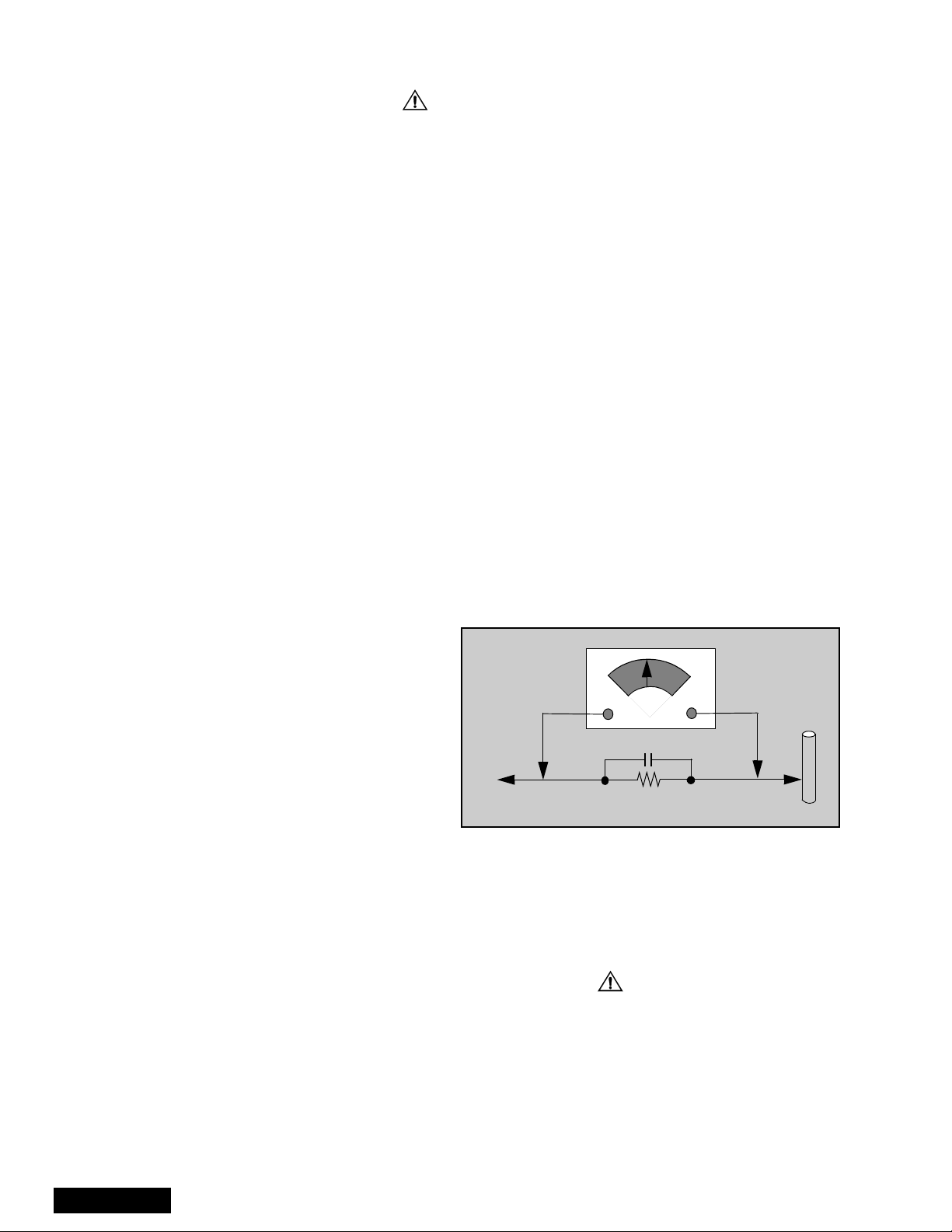
Leakage current hot check (see figure 1)
Plug the AC cord directly into the AC outlet. Do not use
an isolation transformer during the check.
Connect a 1.5kΩ 10 watt resistor in parallel with a
0.15µF capacitor between and exposed metallic part
and ground. Use earth ground, for example a
water pipe.
Using a DVM with a 1000 ohms/volt sensitivity or
higher, measure the AC potential across the resistor.
Repeat the procedure and measure the voltage
present with all other expose metallic parts.
Verify any potential does not exceed 0.75 volt RMS. A
leakage current tester (such a Simpson model 229,
Sencore model PR57 or equivalent) may be used in
the above procedure, in which case any current
measure must not exceed 0.5 milliamp. If any
measurement is out of the specified limits, there is a
possibility of a shock hazard and the PTV must be
repaired and rechecked before it is returned to
the customer.
AC VOLTMETER
COLD
WATER
PIPE
(GROUND)
0.15µF
TO INSTRUMENT’S
EXPOSED METAL
PARTS
Figure 1. Hot check circuit
1500Ω,10W
Insulation test
Connect an insulation tester between an exposed
metallic part and AC line.
Apply 1080VAC/60Hz for 1 second. Confirm that the
current measurement is 0.5mA ~ 2.0mA. Repeat test
with other metallic exposed parts.
X-ray radiation
WARNING: The potential source of x-ray radiation in the
PTV is in the high voltage section and the picture tube.
Note: It is important to use calibrated equipment.
Apply all black video signals (1080i) and confirm high
voltage measures 31.5 ± 1.0kV. If the high voltage is
not within the range, change C514 to 1800pF, 2000pF,
2400pF or 2700pF until the desired value is obtained.
Apply NTSC white pattern and confirm the high voltage
measures 30.1 ± 1.5kV.
Apply HD 1080I white pattern and confirm the high
voltage measures 30.1 ± 1.5kV
-2-
About lead free solder (PbF)
component
Note: Lead is listed as (Pb) in the periodic table of elements.
In the information below, Pb will refer to Lead solder, and PbF will refer to Lead Free Solder.
The Lead Free Solder used in our manufacturing process and discussed below is (Sn+Ag+Cu).
That is Tin (Sn), Silver (Ag) and (Cu) although other types are available.
This model uses Pb Free solder in it’s manufacture due to environmental conservation issues. For
service and repair work, we’d suggest the use of Pb free solder as well, although Pb solder may be
used.
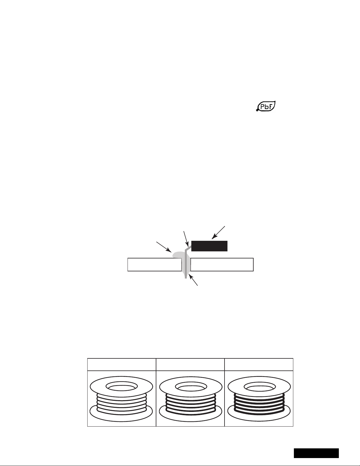
PCBs manufactured using lead free solder will have the PbF within a leaf symbol stamped on the
back of PCB.
Caution
• Pb free solder has a higher melting point than standard solder. Typically the melting
point is 50 ~ 70 °F(30~40°C) higher. Please use a high temperature soldering iron
and set it to 700 ± 20 °F(370± 10 °C).
• Pb free solder will tend to splash when heated too high (about 1100 °For600°C).
If you must use Pb solder, please completely remove all of the Pb free solder on the
pins or solder area before applying Pb solder. If this is not practical, be sure to heat the
Pb free solder until it melts, before applying Pb solder.
• After applying PbF solder to double layered boards, please check the component side
for excess solder which may flow onto the opposite side. (see figure below)
component
remove all of the
excess solder
pin
slice view
solder
Suggested Pb free solder
There are several kinds of Pb free solder available for purchase. This product uses Sn+Ag+Cu
(tin, silver, copper) solder. However , Sn+Cu (tin, copper), Sn+Zn+Bi (tin, zinc, bismuth) solder
canalsobeused.
0.3mm X 100g
0.6mm X 100g 1.0mm X 100g
-3-
ServiceManual
Important safety tests
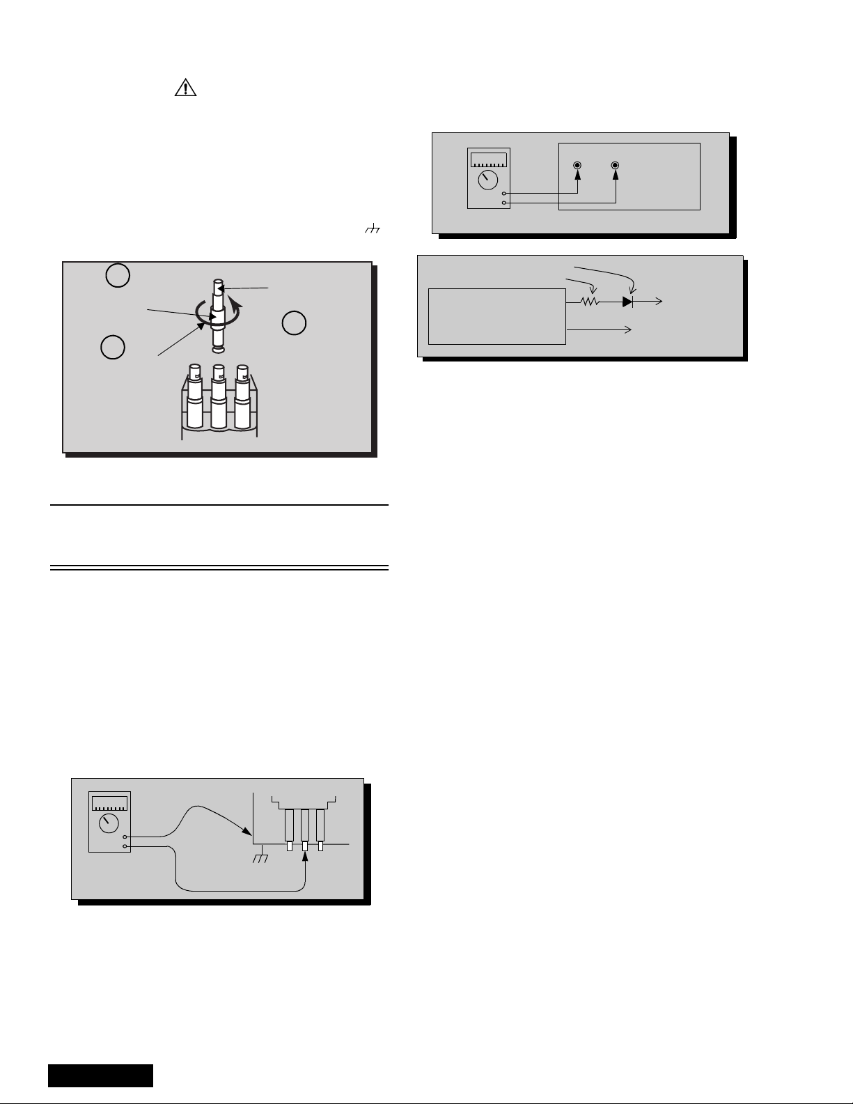
Measuring H.V.
The anode caps are cemented to the CRTs. To gain
access for high voltage measurement, remove the red
CRT’s anode lead from the flyback transformer
distributor. Grasp the anode lead protective cap at its
bottom and squeeze it against the locking cap body
inside, rotate 1/4 turn counter clockwise and pull the
anode lead sleeve out of the FBT distributor. Connect a
high voltage lead (+) from your H.V. meter to the FBT
distributor, and the common (-) to cold ground ( ).
(see figure 2).
1
Grasp protective
Anode lead
rubber cap
3
2
Push & rotate
Discharge to
CRT chassis
cap counterclockwise
to remove
FBT distributor
Figure 2. Removal of FBT leads
Note: Reinsert the anode lead into the FBT
distributor until it is tightly and fully seated.
Turn the locking cap clockwise to lock in place.
(EHT) Protector operation check
With the cabinet back removed, apply a nominal 120V
AC to the PTV.
Over voltage test
Preparation:
1. TurnPTV “OFF”
2. Connect a NTSC signal generator to the
antenna terminal.
3. Connect DVM (+) TPD50 and (-) TPD51 on
D Board (see figure 4)
4. Connect a H.V. meter (static type, class 0.1) with
high voltage leads to high voltage distributor
on FBT. (See figure 4)
TPD51 TPD50
-
+
D-Board
DVM
D-Board
IC802 PIN 2
OR TPD8
Variable
power
supply
MA150
100Ω 1/2 W
(+)
(15~25DC)
(-)
HEAT SINK OF Q551
Figure 4. DVM & power supply c onnection.
5. Connect the 15 ~ 25 V DC variable power supply to
(+) TPD8 or IC802 pin 2 (D-Board) and (-) heat
sink of Q551 (see figure 4).
Procedures:
1. Apply a NTSC white pattern.
2. Turn PTV ON.
3. Adjust the picture or brightness controls so that the
DVM reads 16.5 volts ± 0.5 volts.
4. Increase the variable power supply until set turns
off. The set should turn off at 16.5 volts ± 0.5 volts
(DVM) and high voltage less than 36.4kV.
5. If the DVM reading is other than 16.5 volts ± 0.5
volts, readjust picture or brightness control and
repeat steps 3.
6. Turn off the variable supply and confirm that the set
will turn on with the remote control.
-
+
H.V. METER
ServiceManual
Cold ground
FBT Distributor
CRT
CHASSIS
Figure 3. Measuring H.V.
-4-

Notes about format aspect switching (WX 16:9 or HX 4:3)
and adjustments
Widescreen 16:9 and non-widescreen 4:3 PTVs use the same
light box, for this reason is important to set it to the correct
version (16:9 or 4:3). To change the format please refer to
figure 62 on page 43 on main manual order No MTNC020409C1.
Be sure t o select the correct f ormat for the serviced PTV.
Adjustments for NTSC ZOOM included in main manual order
No MTNC020409C1 does not apply for models included in this
simplified service manual.
-5-
ServiceManual
Importantsafetynotice...................2
Safetyprecautions........................2
Generalguidelines..................2
X-rayprecautions ..................2
Leakagecurrentcoldcheck...........2
Leakagecurrenthotcheck ...........2
Insulationtest .....................2
X-rayradiation.....................2
About lead free solder (PbF) . . . . . . . ........3
SuggestedPbfreesolder............3
Importantsafetytests....................4
MeasuringH.V.....................4
(EHT) Protector operation check. . . . . . . 4
Notes about format aspect switching
(WX16:9orHX4:3)...................5
andadjustments.........................5
Servicenotes ...........................7
Leadless chip component
(surfacemount).................7
Componentremoval ................7
Chip component installation . . ........7
HowtoreplaceFlat-IC...............7
CRTsetup.............................15
Dynamicfocusadjustments..........15
Convergence alignment template . . . . . 16
Service mode (electronic controls). . . . . . . . . 17
Quickentrytoservicemode.........17
To toggle between aging and
servicemodes.................17
Exitingtheservicemode............17
Tocheckcolors...................17
Table of the service adjustment
item available for each format . . . . . . . . . 18
480i Service mode
(electroniccontrols)..................20
480p Service mode
(electroniccontrols)..................22
1080i Service mode
(electroniccontrols)..................24
Partslist ..............................26
Description of abbreviations guide . . . . . . . . 34
Schematicnotes........................35
Featuretable............................9
Boardsdesignation.....................10
PTV-Locationofcontrols................11
Quick reference control operation . . . . . 11
Remote-locationofcontrols.............12
DisassemblyforService.................13
SpeakerGrilleRemoval.............13
Keyboard Removal (7-Key Button) . . . . 13
SpeakersReplacement.............13
CabinetBackLowerRemoval........13
CabinetBackCoverRemoval........13
CabinetFrontRemoval.............14
ScreenAssembly..................14
K-Boardschematicandlayout............37
G-Boardschematicandlayout............38
ServiceManual
-6-
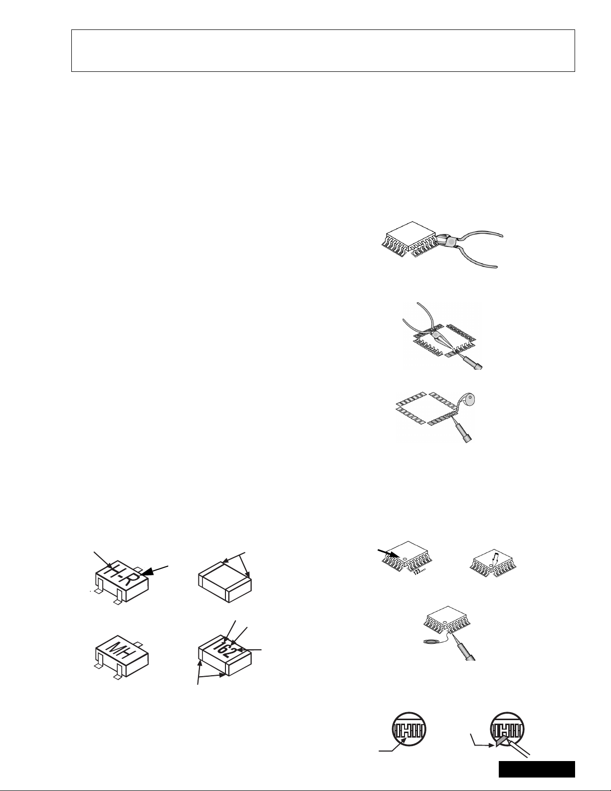
Service notes
Note: These components are affixed with glue. Be careful not to break or damage any foil under the
component or at the pins of the ICs when removing. Usually applying heat to the component for
a short time while twisting with tweezers will break the component loose.
Leadless chip component
(surface mount)
Chip components must be replaced with identical chips
due to critical foil track spacing. There are no holes in
the board to mount standard transistors or diodes.
Some chip capacitor or resistor board solder pads may
have holes through the board, however the hole
diameter limits standard resistor replacement to 1/8
watt. Standard capacitor may also be limited for the
same reason. It is recommended that identical
components be used.
Chip resistor have a three digit numerical resistance
code - 1st and 2nd significant digits and a multiplier.
Example: 162 = 1600 or 1.6kΩ resistor, 0 = 0Ω (jumper).
Chip capacitors generally do not have the value
indicated on the capacitor. The color on the component
indicates the general range of the capacitance.
Chip transistors are identified by a two letter code. The
first letter indicated the type and the second letter, the
grade of transistor.
Chip diodes have a two letter identification code as per
the code chart and are a dual diode pack with either
common anode or common cathode. Check the parts
list for correct diode number.
Component removal
1. Use solder wick to remove solder from component
end caps or terminal.
2. Without pulling up, carefully twist the component
with tweezers to break the adhesive.
3. Do not reuse removed leadless or chip
components since they are subject to stress
fracture during removal.
Chip component installation
1. Put a small amount of solder on the board
soldering pads.
2. Hold the chip component against the soldering
pads with tweezers or with a miniature alligator clip
and apply heat to the pad area with a 30 watts iron
until solder flows. Do not apply heat for more than
3 seconds.
TYPE
Chip components
GRADE
c
c
SOLDER
CAPS
How to replace Flat-IC
- Required tools -
• Soldering iron • De-solder braids
• Sharp pliers (wire
cutters and long nose)
1. Cut the pins of the defective IC with the wire cutter
pliers, and remove it completely away from the
board. If the IC is glued to the board, apply hot air
to complete the removal. CAUTION- Do not pull or
twist the pliers, it may damage the soldering pads
in the board .
Flat-IC
2. Using the soldering Iron and the long nose pliers,
remove the IC pins that are still attached to the
board.
3. Using the de-solder braid and the soldering Iron,
remove the solder from the board soldering pads.
4. Position the new flat IC in place (apply the pins of
the flat IC to the soldering pads where the pins
need to be soldered). Properly determine the
positions of the soldering pads and pins by
correctly aligning the polarity symbol. Start aligning
and soldering Pin No.1, then align and solder the
pin in the apposite corner of the IC, this will help to
align the rest of the pins.
Polarity
symbol
• Magnifier
Soldering
Iron
De-Solder
Braid
Soldering
Iron
b
b
ANODES
MH DIODE
e
e
TRANSISTOR
COMMON
CATHODE
SOLDER
CAPS
CAPACITOR
1ST DIGIT
RESISTOR
2ND DIGIT
MULTIPLIER
=1600 = 1.6k
5. Solder all pins to the soldering pads using a fine
tipped soldering iron.
Solder
Soldering
Iron
6. Check with a magnifier for solder bridge between
the pins or for dry joint between pins and soldering
pads. To remove a solder bridge, use a de-solder
braid as shown in the figure below.
De-Solder
Braid
-7-
Solder
Bridge
Soldering
Iron
ServiceManual

Service notes (continued)
IMPORTANT: To protect against possible damage to
the solid state devices due to arcing or static discharge,
make certain that all ground wires and CRT DAG wire
are securely connected.
CAUTION: The power supply circuit is above earth
ground and the chassis cannot be polarized. Use an
isolation transformer when servicing the PTV to avoid
damage to the test equipment or to the chassis.
Connect the test equipment to the proper ground (( )
or ( )) when servicing, or incorrect voltages will
be measured.
WARNING: This PTV has been designed to meet or
exceed applicable safety and x-ray radiation protection
as specified by government agencies and independent
testing laboratories.
To maintain original product safety design standards
relative to X-ray radiation and shock and fire hazard,
parts indicated with the symbol on the schematic
must be replaced with identical parts. Order parts from
the manufacturer’s parts center using the parts
numbers listed in this service manual, or provide the
chassis number and the part reference number.
For optimum performance and readability, all other
parts should be replaced with components of
identical specification.
ServiceManual
-8-
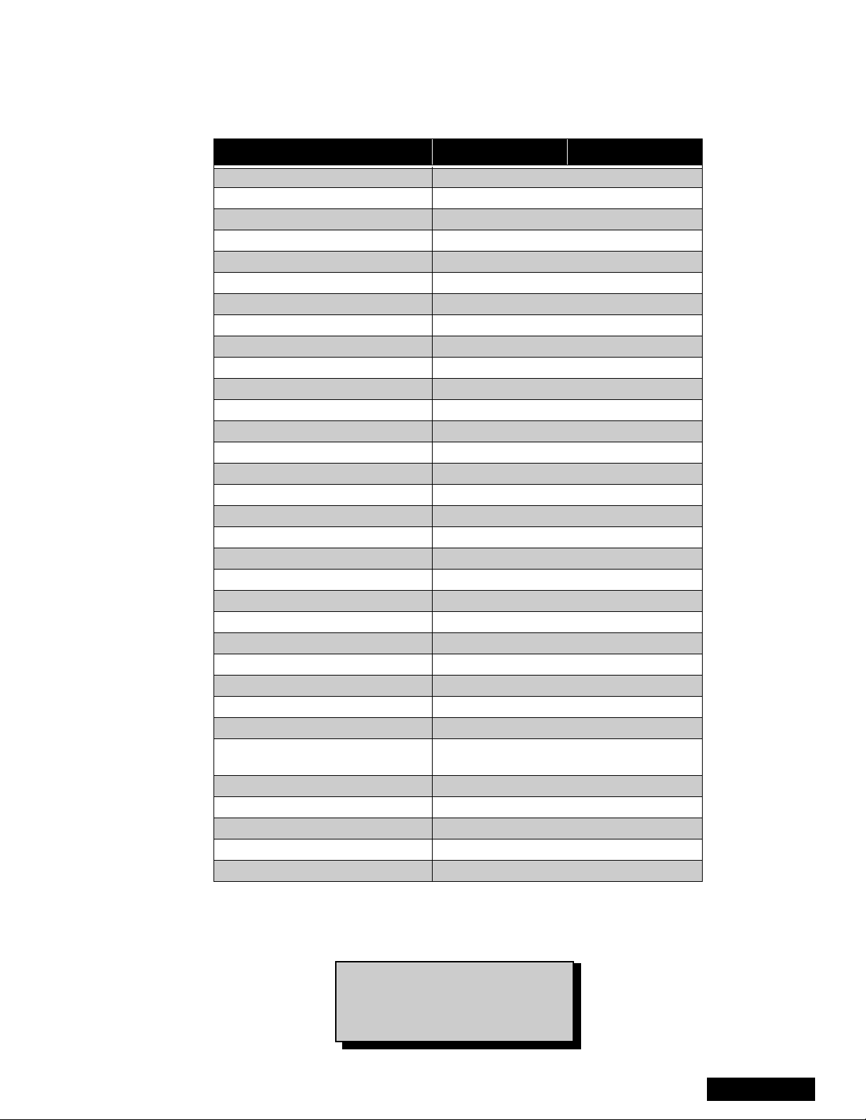
Feature table
FEATURE PT-51HX42F PT-51HX42CF
Chassis P7
Number of channels 181
Menu language Eng/Span/Fr
Closed caption (CC) X
V-Chip (USA/CANADA) X
Picture in Picture (PIP) 2T split
2RF X
Remote control number EUR7603Z30
Screen protector W/PROT SCRN
Comb filter ADV 3D Y/C (NEW)
Color temp X
NEW YNR X
VM X(DIGITAL)
V/A norm BOTH
DIGITAL SCAN RATE 1080i, 480p
NTSC LINE-DOUBLER 480p SMOOTH PROGRESSIVE
MTS/SAP/DBX X
Bass/Bl/Trebcontrol X
AI sound X
SURROUND X
Spatializer/BBE BBE
Built-in audio power 15WX2 (10%)
Number of speakers 2
A/V in (rear/front) 4 (3/1)
S-VHS in (rear/front) 2/1
Audio out Fixed & Variable
COMPONENT INPUT (Y,Pb, Pr) 2
Dimensions mm
WxDxH in
Weight (kg/lbs) 90/198.4
Power source (V/Hz) 120V 60Hz
Anode voltage 31.5kV ± 1.0kV
Video input jack 1Vp-p 75Ω,phono jack
Audio input jack 500mV RMS 47kΩ
1137x653x1361.0
44.8x25.7x53.6
Table 1: Feature T able
Specifications are subject to change
without notice or obligation.
Dimensions and weights are
approximate.
-9-
ServiceManual
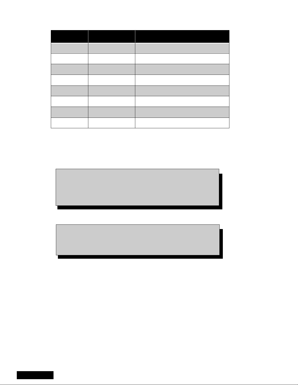
Boards designation
BOARD PART NUMBER BOARD DESCRIPTION
A-Board TNP2AH035 signal processing
D-Board TNPH0371 power and deflection
LB-Board TNP2AA110 blue driver
LG-Board TNP2AA111 green driver
LR-Board TNP2AA112 reddriver
G-Board TNP2AA088 front A/V panel
K-Board TNP2AA087 front button panel
R-Board TNPA0615AB IR receiver
Table 2: Boards designation
Note: The A-Board (
A-Board both tuners, IC2302, IC7001, IC7002, IC871, IC872,
IC873. If any of these components or board is defective repleace
it with a new one and take back the defective board to the service
center.
Notice: When ordering any board, add and ” S” after the board
Example: If Order D-Board, should be ordered as:
TNP2AH035
suffix application.
) is non-serviceable.Exceptfor
TNPH0371
S.
ServiceManual
-10-
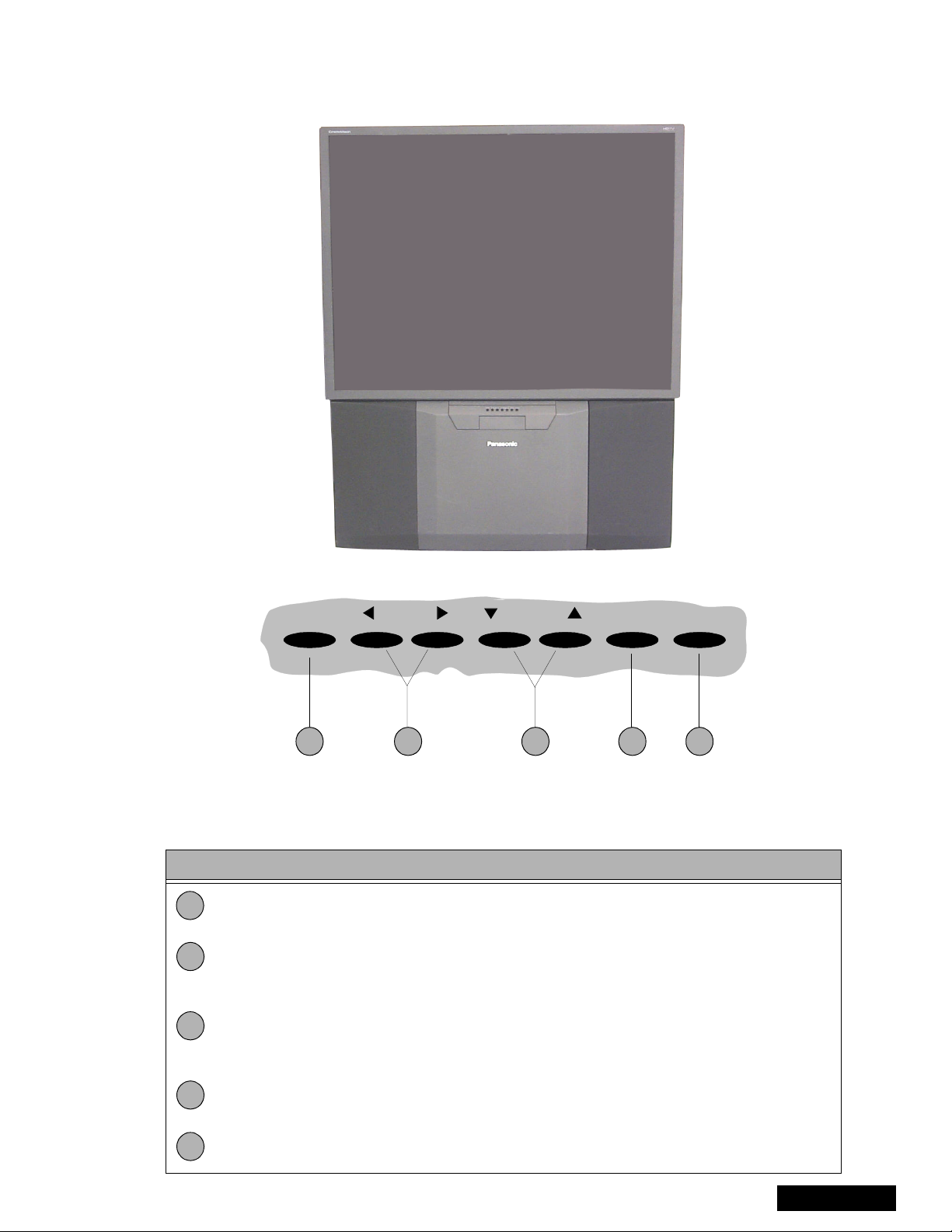
PTV - Location of controls
POWER VOLUME CHANNEL ACTION TV/VIDEO
1 2 4 53
Figure 5. Location o f controls PTV
Quick reference control operation
Quick reference control operation
1
2
3
Power - Press to turn ON or OFF.
Volume - Press to adjust sound level, or to adjust audio menus, video menus, and
select operating features when menus are displayed
Channel - Press to select programmed channels. Press to highlight desired features
when menus are displayed. Also use to select cable converter box channels after
programming remote control infra-red codes (the TV/AUX/CABLE switch must be set
in CABLE position).
4
Action - Press to display main menu and access on screen feature and adjustment
menus.
5
TV/Video - Press to select TV or one of the video inputs, for the main picture or the PIP
frame (when PIP frame is displayed).
-11-
ServiceManual
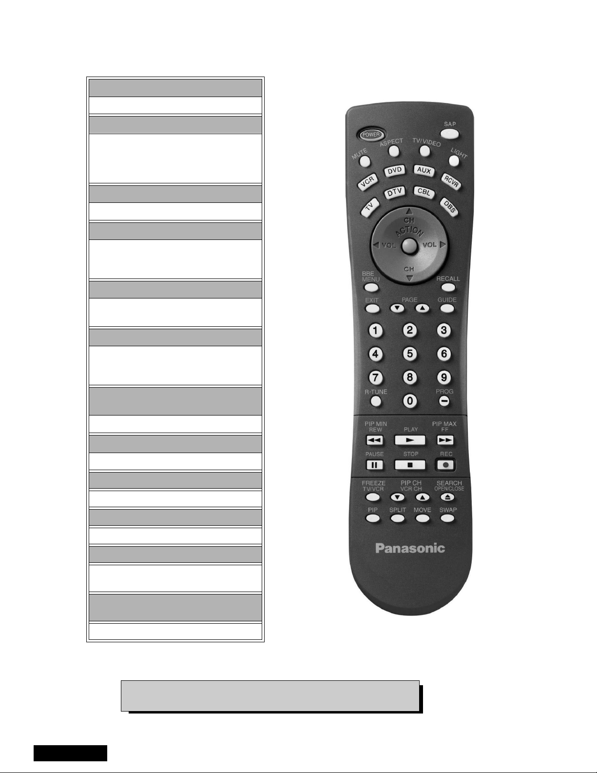
Remote - location of controls
POWER Button
Press to turn ON and OFF.
MUTE Button
Press to mute sound.
A second press resumes sound.
Press also to access and delete
Closed Caption display.
TV, VCR, DVD, CBS/CBL
Component function buttons
VOL (volume) Buttons
Press to adjust TV sound level.
Use with Channel buttons to
navigate in menus.
R-TUNE (Rapid Tune) Button.
Press to switch to the previous
channel.
ACTION Button
Press to displaymain menu and access or
exit on screen features
and adjustment menus.
REW, PLAY, FF, TV/VCR, STOP, PAUSE,
REC & VCR CHANNEL Buttons
Component function buttons.
DBS EXIT& DBS GUIDE Buttons
DBS function buttons.
LIGHT Button
Press to light remote control buttons.
SAP
Access second audio program
ASPECT
Select picture size (ratio) to match
programming format
MOVE, PIP, SPLIT/SIZE, FREEZE, SWAP,
SEARCH, PIP CHANNEL
PIP function buttons
ServiceManual
Figure 6. Location of controls (EUR7603Z30 remote)
For additional information for this remote please refer to the
owner’s manual section remote operation, listed on the parts list.
-12-
 Loading...