

Page 1
Owner’s Manual
High Definition Video Camera
Model No. HDC-Z10000P
Before connecting, operating or adjusting this product, please read the instructions completely.
For USA and Puerto Rico assistance, please call: 1-800-211-PANA(7262) or,
contact us via the web at: http://www.panasonic.com/contactinfo
VQT3U98
Page 2
Dear customer,
Date of Purchase
Dealer Purchased From
Dealer Address
Dealer Phone No.
Model No.
Serial No.
The lightning flash with arrowhead
symbol, within an equilateral
triangle, is intended to alert the user
to the presence of uninsulated
“dangerous voltage” within the
product’s enclosure that may be of
sufficient magnitude to constitute a
risk of electric shock to persons.
CAUTION
CAUTION: TO REDUCE THE RISK OF ELECTRIC
SHOCK, DO NOT REMOVE SCREWS.
NO USER-SERVICEABLE PARTS
INSIDE.
REFER SERVICING TO QUALIFIED
SERVICE PERSONNEL.
The exclamation point within an
equilateral triangle is intended to
alert the user to the presence of
important operating and
maintenance (servicing) instructions
in the literature accompanying the
appliance.
RISK OF ELECTRIC SHOCK
DO NOT OPEN
Thank you for choosing Panasonic!
You have purchased one of the most
sophisticated and reliable products on
the market today. Used properly, we’re
sure it will bring you and your family
years of enjoyment. Pleas e take time to
fill in the information on the right.
The serial number is on the tag loca te d
on the underside of your camera. Be
sure to retain this manual as your
convenient camera informat ion source.
Safety Precautions
WARNING:
TO REDUCE THE RISK OF FIRE, ELECTRIC SHOCK OR PRODUCT DAMAGE,
≥ DO NOT EXPOSE THIS APPARATUS TO RAIN, MOISTURE, DRIPPING OR
SPLASHING AND THAT NO OBJECTS FILLED WITH LIQUIDS, SUCH AS
VASES, SHALL BE PLACED ON THE APPARATUS.
≥ USE ONLY THE RECOMMENDED ACCESSORIES.
DO NOT REMOVE T HE C O VER (OR BAC K); THE R E AR E NO U S ER S ERVICEABLE
≥
PARTS INSIDE. REFER SERVICING TO QUALIFIED SERVICE PERSONNEL.
CAUTION!
DO NOT INSTALL OR PLACE THIS UNIT IN A BOOKCASE, BUILT-IN CABINET OR IN
ANOTHER CONFINED SPACE. ENSURE THE UNIT IS WELL VENTILATED. TO
PREVENT RISK OF ELECTRIC SHOCK OR FIRE HAZARD DUE TO OVERHEATING,
ENSURE THAT CURTAINS AND ANY OTHER MATERIALS DO NOT OBSTRUCT THE
VENTILATION VENTS.
THE FOLLOWING APPLIES ONLY IN THE U.S.A.
The following mark and symbols are located on the bottom of units (High Definition
Video Camera and the battery ch arger).
2
VQT3U98
Page 3
THE FOLLOWING APPLIES ONLY IN THE U.S.A.
HDC-Z10000P
FCC Note:
This equipment has been tested and found to comply with the limits for a Class B dig i tal
device, pursuant to Part 15 of the FCC Rules. These limits are designed to provide
reasonable protection against harmful interference in a residential installation. This
equipment generates, uses, a nd can radia te radio fr equenc y energy and, if not inst alled and
used in accordance with the instructions, may cause harmful interference to radio
communications. However, there is no guarantee that interference will not occur in a
particular installa tion. If this equipment does cause harmful interference to radio or
television recept ion, whic h ca n be determin ed b y tur ning th e eq uipment off and on, the user
is encouraged to try to correct the interference by one or more of the following measures:
≥ Reorient or relocate the receiving antenna.
≥ Increase the separation between the equipment and receiver.
≥ Connect the equipment into an outlet on a circuit different from that to which the receiver
is connected.
≥ Consult the dealer or an experienced radio/TV technician for help.
FCC Caution: To assure continued compliance, follow the at tached installation
instructions and use only shielded interface cables with ferrite
core when connecting to computer or peripheral devices.
Any changes or modifications not expressly approved by the party responsible for
compliance could void the us er’s authority to operate this equipment.
Declaration of Conform ity
Trade Name: Panasonic
Model No.: HDC-Z10000P
Responsible party: Panasonic Corporation of North Amer ica
One Panasonic Way, Secaucus, NJ 07094
Support Contact: Panasonic Consumer Electronics Company
1-800-211-PANA (7262)
This device complies with Part 15 of the FCC Rules. Operation is subject to the following
two conditions: (1) This dev ice may not c ause harmf ul interfer ence, and (2) this device mus t
accept any interference received, including interference that may cause undesired
operation.
VQT3U98
3
Page 4

AC adaptor
This AC adaptor operates on AC between 110 V and 240 V.
But
≥ In the U.S.A. and Canada, the AC adaptor must be connected to a 120 V AC power
supply only.
≥ When connecting to an AC supply out side of th e U.S .A. or Canada , use a plu g ada ptor to
suit the AC outlet configuration.
≥ When connecting to a supply of greater than AC 125V, ensure the cord you use is suited
to the voltage of the AC supply and the rated current of the AC adaptor.
≥ Contact an electrical parts dis tributor for assistance in selecting a s uitable AC plug
adaptor or AC cord set.
Battery charger
This battery charger operates on AC between 100 V and 240 V.
But
≥ In the U.S.A. and Canada, the battery ch arger must be connected to a 120 V AC power
supply only.
≥ When connecting to an AC supply out side of th e U.S .A. or Canada , use a plu g ada ptor to
suit the AC outlet configuration.
≥ When connecting to a supply of greater than AC 125V, ensure the cord you use is suited
to the voltage of the AC supply and the rated current of the battery charger.
≥ Contact an electrical parts dis tributor for assistance in selecting a s uitable AC plug
adaptor or AC cord set.
The unit should be install ed near an accessible AC power outlet, with the power cord
connected directly to i t.
To completely disconnect power from the unit, unplug the power cord from the AC power
outlet.
∫ Concerning the battery
Batteries
1 Battery pack (Li thium ion battery pack)
≥ Use the specified unit to recharge the battery pack.
≥ Do not use the battery pack with equipment other than the specified unit.
≥ Do not get dirt, sand, liquids, or other foreign matter on the terminals.
≥ Do not touch the plug terminals (i and j) with metal objects.
≥ Do not disassemble, remodel, heat or throw into fire.
2 Button-type battery (Lithium battery)
≥ Insert with poles aligned.
≥ Do not touch the terminals (i and j) with metal objects.
≥ Do not recharge, disassemble, remodel, heat or throw into fire.
≥ Keep out of reach of children.
If any electrolyte should come int o con tac t wit h yo ur hands or cl othes, wash i t off th oroughly
with water.
If any electrolyte should come into contact with your eyes, never rub the eyes. Rinse eyes
thoroughly with water, and then consult a doctor.
4
VQT3U98
Page 5
Warning
Risk of fire, explosion and burns. Do not disassemble.
Do not heat the batteries above the following temperatures or incinerate.
Button-type battery 60 oC (140 oF)
Battery pack 60 oC (140 oF)
CAUTION
Danger of explosion if battery is incorrectly replaced. Replace only with the same or
equivalent type recommended by the manufacturer. Dispose of used batteries according
to the manufacturer’s instructions.
∫ Product Identification Marking
Product Location
High Definition Video Camera Bottom
AC adaptor Bottom
Battery charger Bottom
U.S.A. CONSUMERS: ATTENTION:
A lithium ion battery that is recyclable powers the product
you have purchased. Please call 1-800-8-BATTERY for information
on how to recycle this battery.
<For USA-California only>
This product contains a CR Coin Cell Lithium Batte ry which contains Perchlorate Material –
special handling may apply.
See www.dtsc.ca.gov/hazardous waste/perchlorate
.
VQT3U98
5
Page 6

IMPORTANT SAFETY
INSTRUCTIONS
Read these operating instructions carefully before using the unit. Follow the safety
instructions on the unit and the applicable safety instructions listed below. Keep these
operating instructions handy for future reference.
1) Read these instructions.
2) Keep these inst ructions.
3) Heed all warnings.
4) Follow all instructions.
5) Do not use this apparatus near water.
6) Clean only with dry cloth.
7) Do not block any ventilat i on openings.
Install in accordance with the
manufacturer’s instructions.
8) Do not install near any heat sources
such as radiators, heat registers,
stoves, or other apparatus (including
amplifiers) that produce heat.
9) Do not defeat the safety purpose of the
polarized or grounding-type plug. A
polarized plug has two blades with one
wider than the other. A grounding-type
plug has two blades and a third
grounding prong. The wide blade or the
third prong are provided fo r your safety.
If the provided plug does not fit into your
outlet, consult an electrician for
replacement of the obsolete outlet.
11) O nl y us e attachments/a c cessories
specified by the manufacturer.
12) Use only with the
cart, stand, tripod,
bracket, or table
specified by the
manufacturer, or
sold with the
apparatus. When a
cart is used, use caution when moving
the cart/apparatus combination to avoid
injury from tip-over.
13) Unplug this apparatus during lightning
storms or when unused for long periods
of time.
14) Refer all servicing to qualified service
personnel. Servicing is required when
the apparatus has been damage d in any
way, s uc h as power-supply cord or plug
is damaged, liquid has been spilled or
objects have fallen into the apparatus,
the apparatus has been exp osed to rain
or moisture, does not operate normally,
or has been dropped.
10) Protect the power cord from being
walked on or pinched particularly at
plugs, convenience recept acles, and the
point where they exit fr om the
apparatus.
6
VQT3U98
Page 7
Precautions
WARNING
CAUTION
USE & LOCATION
≥ TO AVOID SHOCK HAZARD ... Your
camera and power supply shoul d not be
exposed to rain or moisture. Do not
connect the power supply or operate your
camera if it gets wet. Your camera has
been designed for outdoor use, howeve r it
is not designed to sust ain direct exposure
to water, rain, sleet, snow, sand, dust, or a
direct splashing fro m a pool or even a cup
of coffee. This action could permanently
damage the internal parts of your camera.
Do not attempt to disassemble this unit.
There are no user serviceable parts
inside. Unplug your camera from the
power supply before cleaning.
≥ AS WITH ANY SMALL OBJECT, SD
CARDS CAN BE SWALLOWED BY
YOUNG CHILDREN. DO NOT ALLOW
CHILDREN TO HANDLE THE SD CARD.
≥ DO NOT AIM YOUR CAMERA AT THE
SUN OR OTHER BRIGHT OBJECTS
≥ DO NOT LEAVE THE CAMERA WITH
THE EVF AIMED DIRECTLY AT THE
SUN AS THIS MAY CAUSE DAMAGE TO
THE INTERNAL PARTS OF THE EVF
≥ DO NOT EXPOSE YOUR CAMERA TO
EXTENDED HIGH TEMPERATURE ...
Such as, in direct sunlight, inside a closed
car, ne xt to a heater, etc... This action
could permanently damage the i nternal
parts of your camera.
≥ AVOID SUDDEN CHANGES IN
TEMPERATURE ... If the unit is suddenly
moved from a cold place to a warm place,
moisture may form on the SD card and
inside the unit.
≥ DO NOT LEAVE YOUR CAMERA OR
THE POWER SUPPLY TURNED ON
WHEN NOT IN USE.
≥ STORAGE OF YOUR CAMERA ... Store
and handle your camera in a manner tha t
will not subject it to unnecessary
movement (avoid shaking and striking).
Y our camera contains a sensitive pick-up
device which could be damaged by
improper handling or storage.
CARE
≥ TO CLEAN YOUR CAMERA ... Do not
use strong or abrasive detergents when
cleaning your camera body.
≥ TO PROTECT THE LENS ... Do not touch
the surface of the lens with your hand.
Use a commercial camera lens solution
and lens paper when cleaning the lens.
Improper cleaning can scratch the lens
coating.
≥ TO PROTECT THE FINISH OF YOUR
CAMERA ... Before handling your
camera, make sure your hands and face
are free from any chemical prod ucts , su ch
as suntan lotion, as it may damage the
finish.
-If you see this symbol-
Information on Disposa l in other
Countries outside the European
Union
This symbol is only valid
in the European Union.
If you wish to discard
this product, please
contact your local
authorities or dealer and
ask for the correct
method of disposal.
VQT3U98
7
Page 8

∫ Features
This unit is a single body twin lens type 3D
high-definition video camera. With the
adoption of twin lens format, the
convergence point can be adjusted within
this unit, allowing to record natural and deep
3D video. (l 39)
∫ About the recording format for
recording motion pictures
Y ou can record motion pictures with AVCHD
recording forma ts usi n g th i s un it.
(l 36, 115)
≥ AVCHD 3D and AVCHD Progressive
supported.
AVCHD 3D:
It is possible to record powerful, life-like 3D
full high definition images.
A 3D compatible television compatible to the
frame sequential format is required to view
the 3D full high definition images. (l 91)
AVCHD Progressive:
It is possible to record 2D video in the
highest quality (1080/60p).
∫ Indemnity about recorded
content
Panasonic does not accept any
responsibility for damages directly or
indirectly due to any type of problems that
result in loss of recording or edited content,
and does not guarantee any cont ent if
recording or editing does not work properly.
Likewise, the above also applies in a case
where any type of repair is made to the unit.
∫ Cards that you can use with
this unit
SD Memory Card, SDHC Memory Card
and SDXC Memory Card
≥ 4 GB or more Memory Cards that do not
have the SDHC logo or 48 GB or more
Memory Cards that d o not have t he S DXC
logo are not based on SD Memory Card
Specifications.
≥ Refer to page 22 for more details on SD
cards.
∫ For the purposes of this
owner's manual
≥ The battery pack is referred to as the
“Battery”.
≥ SD Memory Card, SDHC Memory Card
and SDXC Memory Card are referred to
as the “SD card”.
≥ Function that can be used for Recording
Mode:
Function that can be used for Playback
Mode:
≥ Pages for reference are indicated by an
arrow, for example: l 00
8
VQT3U98
Page 9

Contents
Accessories.............................................11
Preparation
Parts identificat ion and handling ..... ... ..12
Power supply.. ... ... ................................. ..17
Charging the battery ......................... 18
Inserting/removing the battery........... 19
Charging and reco rdi n g tim e.... ... ...... 20
Connecting to the AC outlet.............. 21
Preparation of SD cards ......... ... ... ... .......22
Cards that you can use with this
unit .................................................... 22
Inserting/removing an SD card.......... 23
Turning the unit on/off............................24
Selecting a mode ....................................24
Using the LCD monitor/Viewfinder........25
Using the LCD monitor...................... 25
How to use the touch screen ............ 26
LCD monitor adjustment ................... 27
Viewfinder adjustment....................... 28
Recording yourself............................ 28
Setting date and time..............................29
Using the menu scre e n ..........................30
Using with the wireless remote
control......................................................31
Operation of direction buttons/
OK button..... ..................................... 32
Recording
Before recording.....................................33
Formatting cards ........ ... .. .................. 34
Selecting a media to record ...................35
Recording motion pictures ....................36
Convergence point adjustment ......... 39
Recording still pictures..........................45
Intelligent Auto M o de /M a nu a l Mo de......46
Zoom in/out function ..............................48
Ring zoom. ... ..................................... 48
Image Stabilizer Function ......................50
Focus .......................................................51
White Balance .........................................52
Iris adjustment ........................................54
Manual shutter speed.............................56
Audio Input..............................................57
Microphone setu p ... .. ................. ... ... . 57
Audio recording................................. 58
Switching Audio In pu t ....................... 58
Adjusting the audio input level.......... 61
Counter display ...................................... 63
Setting the Time Code .................. ... . 64
Setting the User Info r m a tio n ...... ... .... 65
Setting the Reco rd in g C o un te r ......... 66
USER button ........................ ................... 67
Setting the USER bu tt o n................... 67
Using the USER button..................... 68
Functions of the USER button .......... 69
Useful functions .....................................75
Quick Start ........................................ 75
Zebra ................ ... ... .......................... 76
Color Bar Screen .............................. 76
Switching the screen indications/
mode informatio n di sp la y.................. 77
Using of Operation Icons....................... 78
Playback
Motion picture/Still picture playback....79
Motion picture playback us ing
operation icon ................. ... ............... 82
Useful functions .....................................84
Creating still picture from motion
picture ............... ... ... .. ........................ 84
Repeat Playba ck.......... ................. ... . 84
Resuming the previous playback...... 84
Playback scenes by the selected
format .. ... ... ........................................ 85
Playing back still pictures by date..... 85
Deleting scene s/ stil l p ic t ure s ................ 86
Protecting scenes/still pictures ......... 87
Watching Video/Pictures on your TV.... 88
Connecting with a HDMI cable ......... 90
Listening in 5.1 channel sound......... 90
Connecting with the AV multi
cable ........... ... .................................. . 90
Viewing with 3D compatible TV............. 91
PreparationRecordingPlaybackMenuDisplayOthers Editing
VQT3U98
9
Page 10

Editing
Others
With a PC .................................................93
What you can do with a PC............... 93
End User License Agreement........... 95
Operating envi ronment ......... ... ... ...... 97
Installation....................................... 100
Connecting to a PC.................. ....... 102
About the PC displa y .... ................ .. 10 3
Starting HD Write r XE 1.0 ........... .... 104
Reading the operating instructions
of the software applica tio n s............. 104
If using Mac..................................... 105
Dubbing .................................................106
Dubbing with a Blu-ray disc
recorder, video device, etc. ............. 106
Menu
Using the Menu ......... ............................ 110
Camera Setup................................. 110
Recording Setup ............................. 115
Switch and display setting............... 122
Other Functions .............................. 127
Video Setup..................................... 131
Picture Setup ........................ ... ... .. .. 131
Display
Indications.............................................132
Messages...............................................134
Troubleshooting ...................................135
About recovery................................ 139
Cautions for use ...................................140
About copyright....................................146
Recording modes/approximate
recordable time .....................................147
Approximate number of recordable
pictures..................................................148
Specifications ....................................... 149
Optional accessories ...........................153
Accessory Order Form
(For USA and Puerto Rico
Customers) ..................................... 154
Limited Warranty (ONL Y FOR U.S.A.
AND PUERTO RICO).............................155
Useful Information
(Only For Latin American
Countries).... ..........................................157
Index ...................................................... 158
10
VQT3U98
Page 11
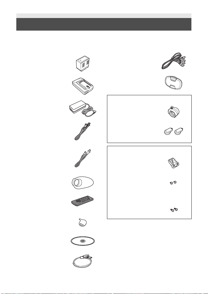
Accessories
Check the accessories before using this unit.
Keep the accessories out of reach of children to prevent swallowing.
Product numbers correc t as of Oct. 2011. These may be subject to change.
Battery pack
CGA-D54
AV multi cable
K1HY12YY0008
Battery charger
DE-A88B
AC adaptor
VSK0725
AC cable
(for AC adaptor)
K2CB2CB00022
AC cable
(for Battery charger)
K2CA2CA00025
Eye cup
VMG2030
Remote control
(Battery built-in)
N2QAEC000024
Stylus pen
VGQ0C14
CD-ROM
Software
Lens cap
VYK5H20
VYC1083
Microphone holder
VYC1079
INPUT terminal cap
(2 caps)
VJF1468
VYC0890
Microphone holder
adaptor
Microphone holder
screws
6 mm (0.24 q) length
(2 screws)
12 mm (0.47 q) length
(2 screws)
≥ Keep the microphone holder screw,
microphone holder adaptor and INPUT
terminal cap out of reach of children to
prevent swallowing.
USB cable
K2KYYYY00141
11
VQT3U98
Page 12
Preparation
5
2
134
6
7
8
9
10
11 12
13
14
15
16
17
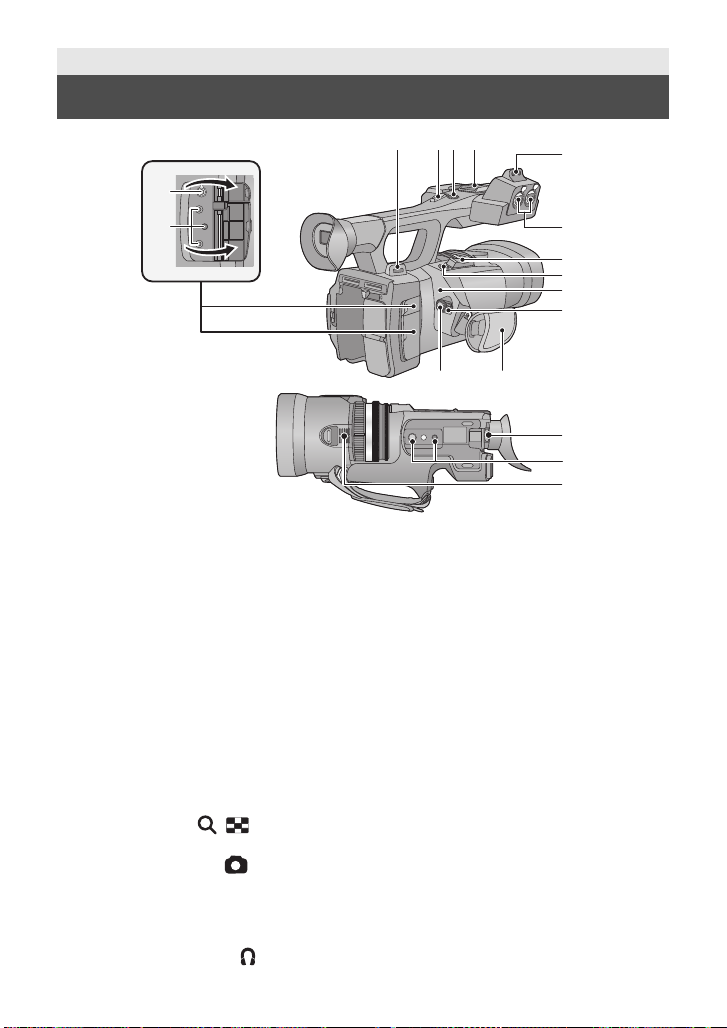
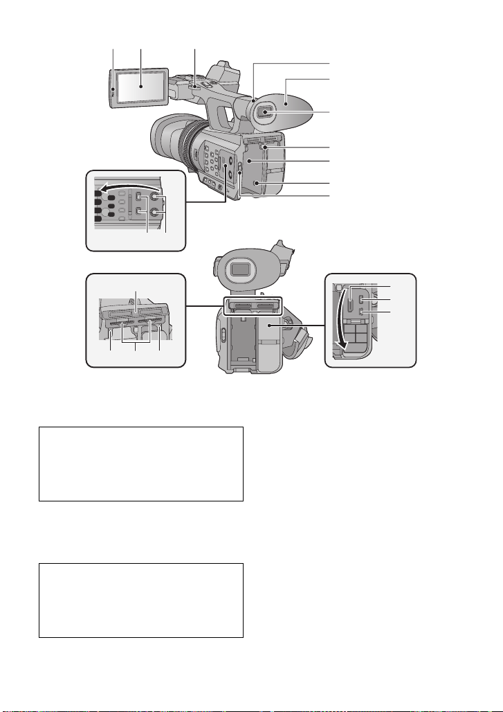
Parts identification and handling
1 Shoulder strap fixture
2 Sub zoom lever (l 48,126)
≥ This lever functions in the same manner
as the zoom lever.
3 Sub recording start/stop button
(l 33, 126)
≥ This button functions in the same manner
as the recording star t/stop button.
4 Accessory shoe
5 Microphone holder attchment part
(l 15)
6 Audio input terminals 1, 2 (XLR 3 pin)
[AUDIO INPUT1,2] (l 16, 59)
7 Zoom lever [T/W] (In Recording
Mode) (l 48)
Vo lume lever [rVOLs]/Thumbnail
display switch [ / ] (In Playback
Mode) (l 80)
8 Photoshot button [ ] (l 45)
9 Status indicator (l 24)
10 Power switch (l 24)
11 Recording start/stop button (l 36)
12 Grip belt (l 15)
13 Headphone terminal [ ] (l 78)
12
VQT3U98
14 Camera remote jack [CAM REMOTE]
[CONV.] (2.5 mm (0.1 q) super mini jack)
It is possible to adjust the covergence point
with the remote control connected (optional).
≥ Operations on the remote control
(optional) will be given priority.
[CAM REMOTE] (3.5 mm (0.14q) mini jack)
It is possible to adjust the focus or iris with
the remote control connected (optional).
≥ It is not possible to use the remote control
(optional) in the Intelligent Auto Mode.
[ZOOM S/S] (2.5 mm (0.1q) super mini jack)
It is possible to operate zoom ope ration or
recording start/stop with t he remote control
connected
≥ Do not connect any equipment except the
15 Eyepiece corrector lever (l 28)
16 Tr ipod receptacle (l 16)
17 Inlet (cooling fan ) (l 34)
(optional).
remote control (optional) to the camera
remote jack. Brightness of the image may
change or it may not focus when an
equipment other than the remote control
(optional) is connected.
Page 13
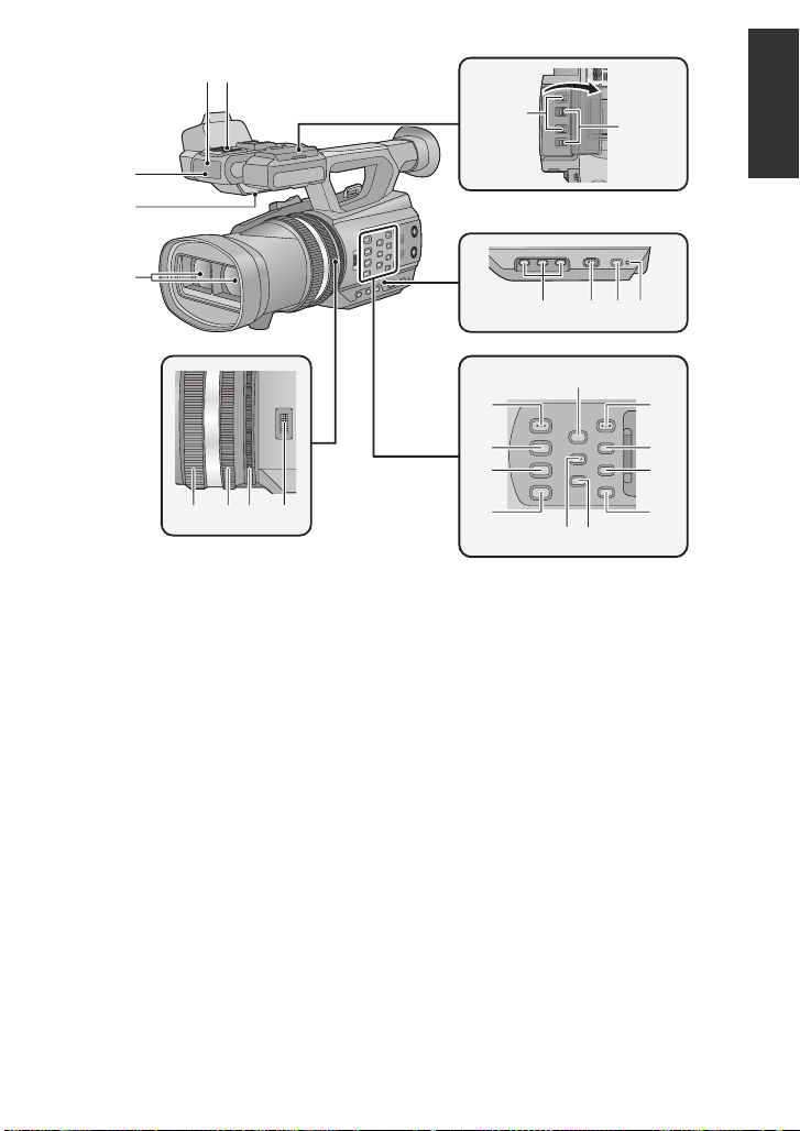
18 Wireless remote control sensor
20
21
22
23
24
29 30 31 32
25 26 2728
34
33
40
41
42
43
35
36
37
38 39
18
19
(l 32)
19 Internal microphones
20 Recording lamp (l 127)
21 Speaker
22 Lens (l 16)
23 INPUT 1, 2 (LINE/MIC) switc he s
(l 59)
24 INPUT 1, 2 (+48V) switches (l 59)
25 User 1, 2, 3 buttons [USER1, USER2,
USER3] (l 67)
26 Intelligent auto/Manual switch
[iA/MANU] (l 46)
27 Quick start button [QUICK START]
(l 75)
28 Quick start lamp (l 75)
29 Focus ring (l 51)
30 Zoom ring (l 48)
31 Iris ring (l 54)
32 Convergence dial [CONV.] (l 40)
33 3D guide button [3D GUIDE] (l 41)
34 Iris auto/Manual button [IRIS A/M]
(l 54)
35 Focus auto/Manual/¶ button
[FOCUS A/M/¶] (l 51)
36 Optical image stabilizer button
[O.I.S.] (l 50)
37 White balance button [W.B.] (l 52)
38 Zebra button [ZEBRA] (l 76)
39 Color Bar Screen button [BARS]
(l 76)
40 Menu button [MENU] (l 30)
41 Display/Mode check button [DISP/
MODE CHK] (l 68, 77)
42 Counter button [COUNTER] (l 63)
43 Counter reset button [RESET]
(l 65, 66)
13
VQT3U98
Page 14
47
48
49
50
51
52
53
45
44
46
54 55
56
58 5957
60
61
62
44 LCD monitor extract part [PULL]
(l 25)
45 LCD monitor (Touch screen) (l 26)
Due to limitations in LCD production
technology , there may be some tiny bright
or dark spots on th e LCD monitor scr een.
However, this is not a malfunction and
does not affect the recorded picture.
46 Shoulder strap fixture
47 Eye cup attachment part (l 15)
48 Eye cup (l 15)
49 Viewfinder (l 28)
Due to limitations in LCD production
technology , there may be some tiny bright
or dark spots on the viewf i nder screen.
However, this is not a malfunction and
does not affect the recorded picture.
50 Battery release button [PUSH] (l 19)
51 Battery holder (l 19)
14
VQT3U98
52 DC input terminal [DC IN] (l 21)
≥ Do not use any other AC adaptors except
the supplied one.
53 Mode switch (l 24)
54 CH1, CH2 switches [CH1, CH2] (l 59)
55 Audio control knobs [CH1, CH2]
(l 62)
56 SD Card slot cover (l 23)
57 Access lamp (card 1) (l 23)
58 Card slot 1 (left)/
Card slot 2 (right) (l 23)
59 Access lamp (card 2) (l 23)
60 HDMI connector [HDMI] (l 88)
61 AV multi connector [AV MULT I]
(l 88, 109)
≥ Use the AV multi cable (only the supplied
cable).
62 USB terminal [USB 2.0] (l 102, 107)
Page 15
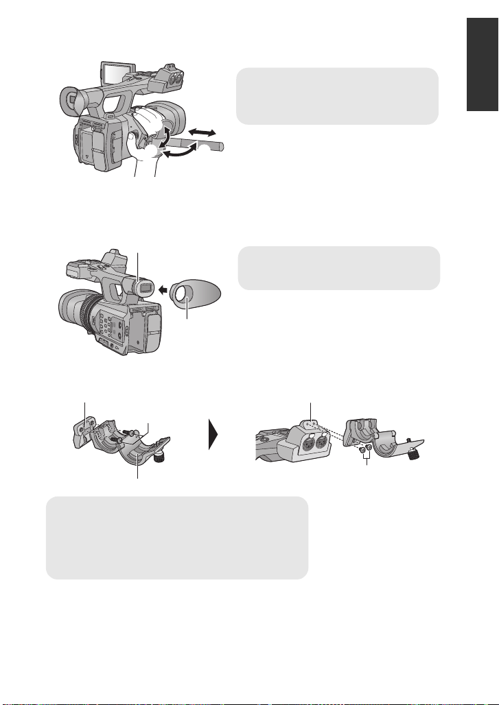
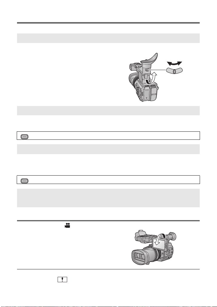
∫ Adjust the length of the grip belt so that it fits your hand.
1, 2 Flip the belt cover and the belt.
3 Adjust the length.
4, 5 Replace the belt.
A Notch
B Protrusion
C Microphone holder adaptor
D Microphone holder
E Microphone holder screws (12 mm) (0.47q)
F Microphone holder attchm ent part
G Microphone holder screws (6 mm) (0. 24q)
∫ Attaching the eye cup
Attach by aligning th e notc h of the e ye cup att achment par t with the p rotrusi on at th e insid e of
the eye cup.
∫ Attaching the microphone holder
≥ Attach by using a commercially available screw driver.
≥ When attaching an external microphone (optional) to the microphone holde r attchment
part, use the supplied microphone holder and microphone holder adapt or.
≥ The microphone holder is set up so that a 21 mm (0.83q) external microphone can be
attached. Check in advance whether the microphone you wish to use can be attached.
15
VQT3U98
Page 16
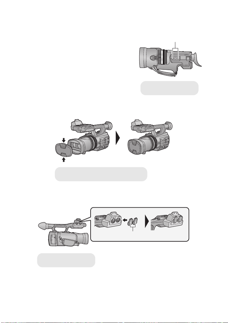
≥ When attaching the microphone ho lder and the microphone holder adaptor, be sure to
A Tripod receptacle
Attach or remove it by pinching on it.
B INPUT terminal cap
tighten the screws firml y even though you might hear a squeaking sound.
∫ Attaching the tripod
≥ There are tripod mounting holes that are
compatible with 1/4-20UNC and 3/8-16UNC
screws. Use the size that matches the diameter of
the tripod’s fixing screw.
≥ If you attach a tripod which has 5.5mm (0.22 q)
screw or larger, it may damage this unit.
∫ Attaching the lens cap
Protect the lens surface with the lens cap while the unit is not used.
∫ Attaching the INPUT terminal cap
Attach the INPUT terminal cap while the audio input terminals 1, 2 (XL R 3 pin) is not used.
16
VQT3U98
Page 17

Preparation
Power supply
∫ About batteries that you can use with this unit
The battery that can be used with this unit is CGA-D54.
It has been found that counterfeit battery packs which look very similar to the
genuine product are made available to purchase in some markets. Some of these
battery packs are not adequately protected with internal protection to meet the
requirements of appropriate safety standards. There is a possibility that these
battery pack s may l ead to fi re o r exp losio n. Pleas e be ad vise d th at we ar e not lia ble
for any accident or failure occurr ing as a r esult of use of a counte rf eit bat tery p a ck.
To ensure that safe products are used we would recommend that a genuine
Panasonic battery pack is used.
17
VQT3U98
Page 18
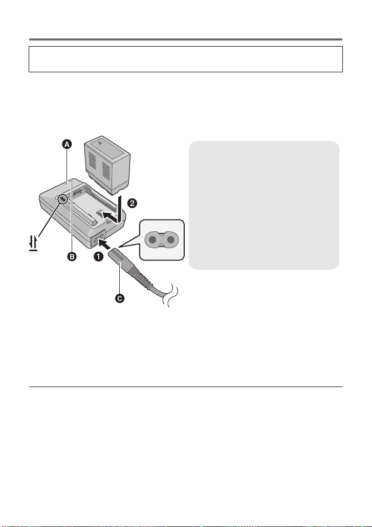
Charging the battery
Charging lamp [CHARGE] A
Lights up:
Charging (Battery charging time: l 20)
Goes off:
Charging completed
Flashing:
Be sure to connect the un i t co r re ct ly
(l 142)
Power lamp B
≥ This will light up when the AC cable is
connected.
When this unit is purchased, the battery is not charged. Charge the battery fully
before using this unit for the first time.
Important:
≥ Do not use the AC cable with any other equipment as it is designed only for this unit.
Also, do not use the AC cable from other equipment with this unit.
≥ It is recommended to charge the battery in a temperatu re between 10 oC and 30 oC
(50 °F and 86 °F).
(The battery temperature should also be the same.)
C AC cable (K2CA2CA00025; supplied)
≥ Insert the plugs as far as they will go.
1 Connect the AC cable to the battery charger and the AC outlet.
≥ Use the AC cable (K2CA2CA00025; supplied) dedicated for the battery charger.
2 Insert the battery into the battery charger by aligning the arrows.
≥ We recommend using Panasonic batteries (l 11, 20, 153).
≥ If you use other batteries, we cannot guarantee the quality of this product.
≥ Do not heat or expose to flame.
≥ Do not leave the battery(ies) in an automobile ex posed to direct sunlight for a long period
of time with doors and windows closed.
18
VQT3U98
Page 19
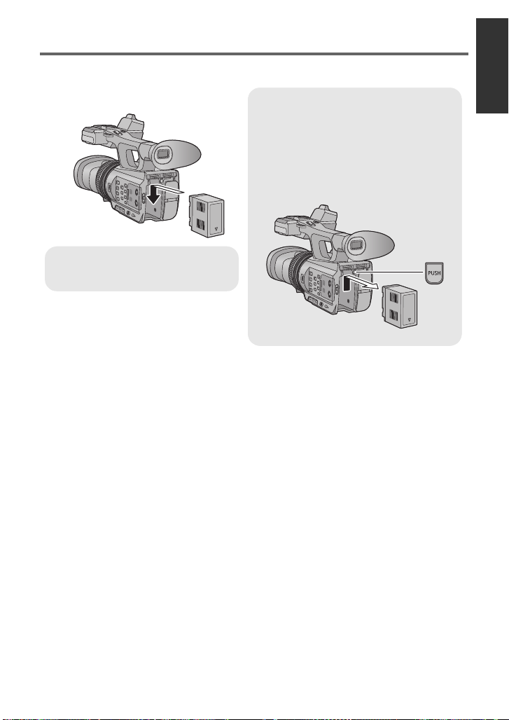
Inserting/removing the battery
Removing the battery
Make sure that the power switch is set to
OFF and the status indi cator is turned off,
and then remove by holding onto it taking
care not to drop. (l 24)
While pushing the PUSH button, remove
the battery.
Insert the battery until it clicks and
locks.
Install the battery by inserting it in the direction shown in the figure.
19
VQT3U98
Page 20
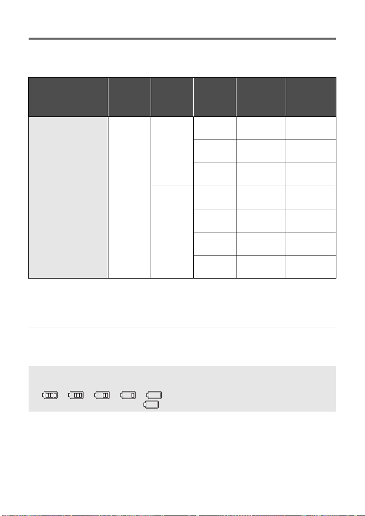
Charging and recording time
∫ Charging/Recording time
≥ Temperature: 25 oC (77 oF)/humidity: 60%RH
≥ When using the viewfinder (times in parentheses are when using the LCD monitor)
Battery model
number
[Voltage/Capacity
(minimum)]
Supplied battery/
CGA-D54 (optional)
[7.2 V/5400 mAh]
≥ These times are approximations.
≥ The indicated charging time is f or when the batter y has been disc harged compl etely.
Charging time and recordable time vary depending on the usage conditions such as
high/low temperature.
Charging
time
5h30min
3D/2D
Recording
Mode
3D
Recording
Mode
2D
Recording
Mode
Recording
format
1080/60i
1080/30p
1080/24p
1080/60p
1080/30p
1080/24p
PH, HA, HE6h25min
Maximum
continuously
recordable
time
4h25min
(4 h)
4h35min
(4 h 10 min)
4h55min
(4 h 20 min)
6h15min
(5 h 45 min)
6h35min
(6 h)
6h55min
(6 h 15 min)
(5 h 55 min)4h(3h40min)
Actual
recordable
time
2h45min
(2h30min)
2h50min
(2h35min)
3h5min
(2h40min)
3h55min
(3h35min)
4h5min
(3h45min)
4h20min
(3h55min)
≥ The actual recordable time refers to the recorda ble t ime when repeat ed ly st art ing/s toppin g
recording, turning the unit on/off, moving the zoom lever etc.
≥ The batteries heat up after use or charging. This is not a malfunction.
Battery capacit y indica tion
≥ The display changes as the battery capacity reduces.
####
If the battery discharges, then will flashes red.
20
VQT3U98
Page 21
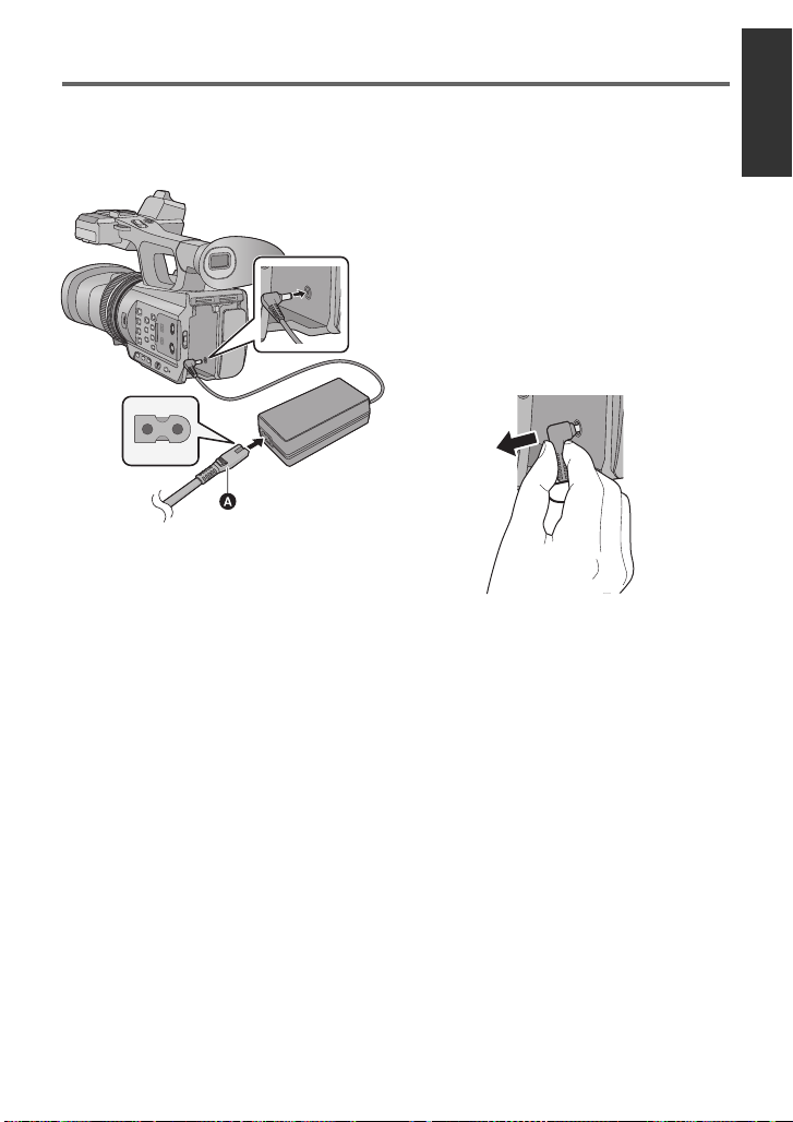
Connecting to the AC outlet
Important:
≥ Use the supplied AC adaptor. Do not use the AC adaptor of another device.
≥ Do not use the AC cable with any other equipment as it is designed only for this unit.
Also, do not use the AC cable from other equipment with this unit.
1 Connect the AC cable to the
AC adaptor and the AC outlet.
≥ Use the AC cable (K2CB2CB00022;
supplied) dedicated for the AC ada ptor.
2 Connect the AC adaptor to the
DC input terminal [DC IN].
∫ Removing the AC adaptor
A AC cable (K2CB2CB00022; supplied)
≥ Insert the plugs as far as they will go.
≥ Make sure to set the power switch to OFF
and the status indi cator is turned off when
disconnecting the AC ada ptor.
21
VQT3U98
Page 22
Preparation
32
Preparation of SD cards
The unit can record motion pictures or still pictures to an SD card.
This unit (an SDXC compatible device) is compatible with SD Memory Cards, SDHC
Memory Cards and SDXC Memory Cards. When using an SDHC Memory Card/SDXC
Memory Card with other equipment, check the equipment is compatible with these
Memory Cards.
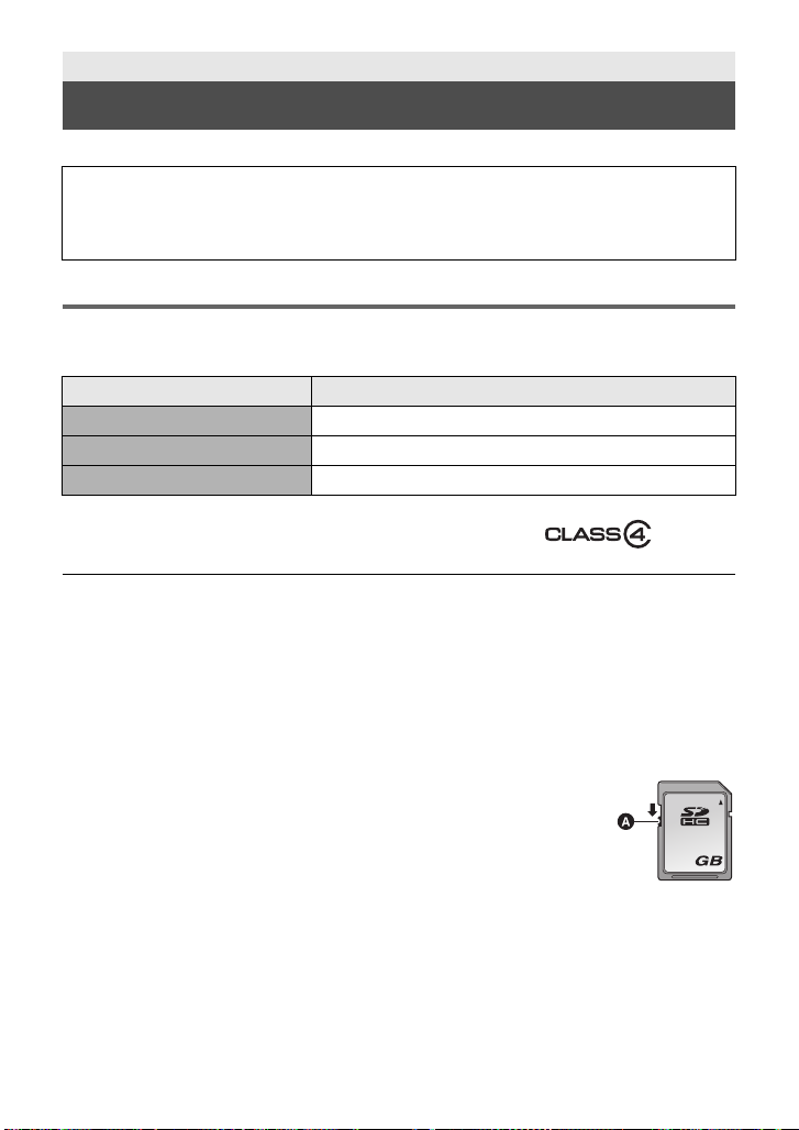
Cards that you can use with this unit
Use SD cards conforming to Class 4 or higher of the SD Speed Class Rating* for
motion picture record ing.
Card type Capacity
SD Memory Card 512 MB/1 GB/2 GB
SDHC Memory Card 4GB/6GB/8GB/12GB/16GB/24GB/32GB
SDXC Memory Card 48 GB/64 GB
* SD Speed Class Rating is the speed
standard regarding continuous writing.
Check via the label on the card, etc.
≥ Please confirm the latest information about SD Memory Cards/SDHC Memory Cards/
SDXC Memory Cards that can be used for motion picture recording on the following
website.
http://panasonic.jp/support/global/cs/e_cam
(This website is in English only.)
≥ Operation of the SD Memory Cards 256 MB or less is not guaranteed. Also, the SD
Memory Card 32 MB or less cannot be used for the motion picture recording.
≥ 4 GB or more Memory Cards that do not have the SDHC logo or 48 GB or more Memory
Cards that do not have the SDXC logo are not based on SD Memory Card Specifications.
≥ When the write-protect switch A on SD card is locked, no recording,
deletion or editing will be possible on th e card.
≥ Keep the Memory Card out of reach of children to prevent swallowing.
e.g.:
22
VQT3U98
Page 23
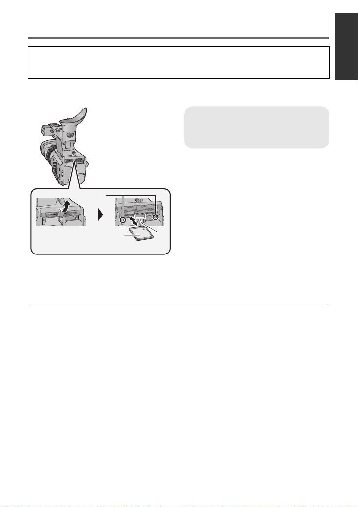
Inserting/removing an SD card
When using an SD card not from Pana sonic, or one previously used on other equipment,
for the first time on this unit, format the SD card. (l 34) When the SD card is formatted, all
of the recorded data is deleted. Once the data is deleted, it cannot be restored.
Caution:
Check that the access lamp has gone off.
Access lamp A
≥ When this unit is accessing the SD
card, the access lamp lights up.
1 Open the SD card slot cover
and insert (remove) t he SD
card into (from) the card slot
B.
≥ One SD card can be inserted into each of
the card slot 1 and the card slot 2.
≥ Face the label side C in the direction
shown in the illustration and press it
straight in as far as it will go.
≥ Press the center of the SD card and then
pull it straight out.
2 Securely close the SD card slot
cover.
≥ Securely close it until it clicks.
≥ Do not touch the terminals on the back of
the SD card.
≥ Do not apply strong shocks, bend, or drop
the SD card.
≥ Electrical noise, static electricity or the
failure of this unit or the SD card may
damage or erase the dat a st ored on the
SD card.
≥ When the card access lam p is lit, do not:
jRemove the SD card
jTurn the unit off
jInsert and remove the USB cable
jExpose the unit to vibrations or shock
Performing the above while the lamp is on
may result in damage to data/SD card or
this unit.
≥ Do not expose the terminals of the SD
card to water, dirt or dust.
≥ Do not place SD cards in the following
areas:
jIn direct sunlight
jIn very dusty or humid areas
jNear a hea ter
jLocations susceptible to significant
difference in temperat ure (cond ensation
can occur.)
jWhere static electricity or
electromagnetic waves occur
≥ To protect SD cards, return them to their
cases when you are not using th em.
≥ About disposing of or giving away the SD
card. (l 144)
VQT3U98
23
Page 24
Preparation
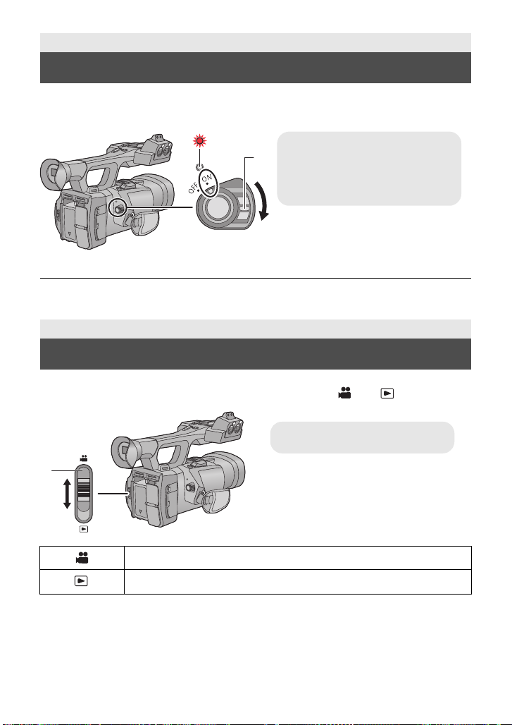
To turn off the unit
Set the power switch to OFF while
pressing the lock release button.
The status indicator goes off.
C Mode switch
Turning the unit on/off
Set the power switch to ON while pressing the lock release button B to
turn on the unit.
A The status indicator lights on.
≥ To turn on the unit again after the [ECO NO MY (BATT)] or [ECONOMY (AC)] is activated,
set the power switch to OFF on ce , an d then to ON ag a in. (l 128)
Preparation
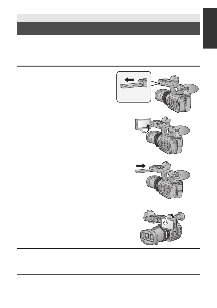
Selecting a mode
Change the mode to recording or pl ayback.
Operate the mode switch to change the mode to or .
24
VQT3U98
Recording Mode (l 36, 45)
Playback Mode (l 79)
Page 25
Preparation
Using the LCD monitor/Viewfinder
The viewfinder is turned off and the LCD monitor is turned on when the LCD monitor is
extracted. The viewfinder is turned on when the LCD monitor is retracted.
Live image recording or 3D recordings can be viewed in 3D on the LCD monitor.
Using the LCD monitor
1 Extract the LCD monitor in the
direction as indicated in the
figure.
≥ Hold the LCD monitor extract part A when
pulling out.
2 Rotate to the position that is easy to
view.
To retract the LCD mo nitor
Retract as show n in th e fi g ur e wit h th e LCD facing
downward.
Range of rotation of the LCD monitor
≥ It can rotate up to 270o B towards the lens.
≥ There are differences in the way that di fferent people experience 3D images.
Check from a position directly in front of and at arou nd 30 cm (0. 98 feet) from the
LCD monitor , wh ere you can easily see picture.
25
VQT3U98
Page 26
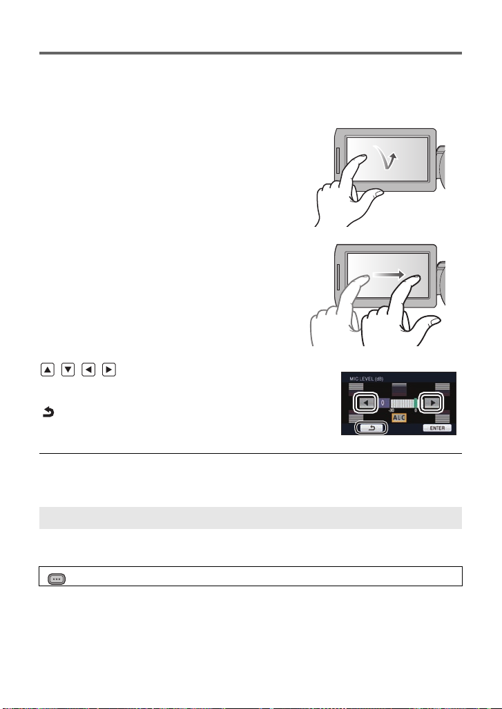
How to use the touch screen
You can operate by directly touching the LCD monitor (touch screen) with your finger.
It is easier to use the stylus pen (supplied) for detaile d operati on or if it is hard to oper ate with
your fingers.
∫ Touch
Touch and release the touch screen to s elect icon or
picture.
≥ Touch the center of the icon.
≥ Touc hing the touch screen will not operate while
you are touching another p art of the touch screen.
∫ Slide while touching
Move your finger while pressing on the touch screen.
∫ About the operation icons
///:
These icons are used to switch the menu and thumbnail
display page, fo r item selection and setting etc.
:
Touch to return to the previous screen such as when
setting menus.
≥ Do not touch the LCD monitor with hard pointed ti ps, such as ball point pens.
≥ Perform the touch screen c alibration when the touch is not recognized or wrong locati on is
recognized.
[CALIBRATION]
Perform the touch screen calibration if a different object to the one touched is selected.
1 Select the menu. (l 30)
MENU
: [OTHER FUNCTION] # [CALIBRATION] # [YES]
≥ Touc h [ENTER].
2Touch the [_] that appears on the screen with the supplied stylus pen.
≥ Touc h [_] in sequence (up left # down left # down right # up right # center).
3 Touch [ENTER].
26
VQT3U98
Page 27
LCD monitor adjustment
MENU
≥ These settings will not affect the images actually recorded.
[POWER LCD]
This makes it easier to view the LCD monitor in bright places including outdoors.
Select the menu. (l 30)
MENU
: [SW & DISP SETUP] # [POWER LCD]# [ON]
≥ It cannot be set when LCD monitor is set to 3D viewing.
≥ When the AC adaptor is in use, [POWER LCD] is set to [ON] automatically.
≥ Recordable time with the battery is shortened when the LCD is made brighter.
[LCD SET]
It adjusts brightness and color density on the LCD monitor.
1 Select the menu. (l 30)
: [SW & DISP SETUP] # [LCD SET] # [YES]
2 Touch the desired setting item.
[COLOR]: Color level of the LCD monitor
[BRIGHTNESS]: Brightness of the LCD monitor
[CONTRAST]: Contrast of the LCD monitor
3 Touch / to adjust settings.
4 Touch [ENTER].
≥ Touc h [EXIT] to exit the menu screen.
27
VQT3U98
Page 28
Viewfinder adjustment
MENU
≥ These settings will not affect the images actually recorded.
Adjusting the field of view
It adjusts the fiel d of view to show the image on the viewfinder clearly.
1 Adjust the viewfinder according to the
position that is easy to view.
≥ Be careful not to trap your fingers when moving the
viewfinder.
≥ The viewfinder can be lifted vertically up to
approximately 90o.
≥ Retract the LCD monitor and turn on the viewfinder.
2 Adjust the focus by operating the eyepiece
corrector lever.
[EVF SET]
Brightness of the viewfinder can be switched.
Select the menu. (l 30)
: [SW & DISP SETUP] # [EVF SET] # [BRIGHT]/[NORMAL]/[DARK]
[EVF COLOR]
The recording images or playback images on the viewfinder can be selected between color/
black and white.
Select the menu. (l 30)
MENU
: [SW & DISP SETUP] # [EVF COLOR]# [ON] or [OFF]
[ON]: Displayed in color
[OFF]: Displayed in black and white
Recording yourself
≥ Change the mode to .
Rotate the LCD monitor towards the lens
side.
≥ Displaying during the recording yourself
can be switched by setting
[SELF SHOOT]. (l 126)
≥ Only some indications will appear on the screen when the [SELF SHOOT] is set to
[MIRROR]. When
and check the warning/alarm indication. (l 134)
28
VQT3U98
appears, retu rn the dir ection of the LCD monitor to normal posi tion
Page 29
Preparation
MENU
Setting date and time
When the unit is turned on for the first time, a message asking you to set the date and time
will appear.
Select [YES] and perform steps 2 to 3 below to set the date and time.
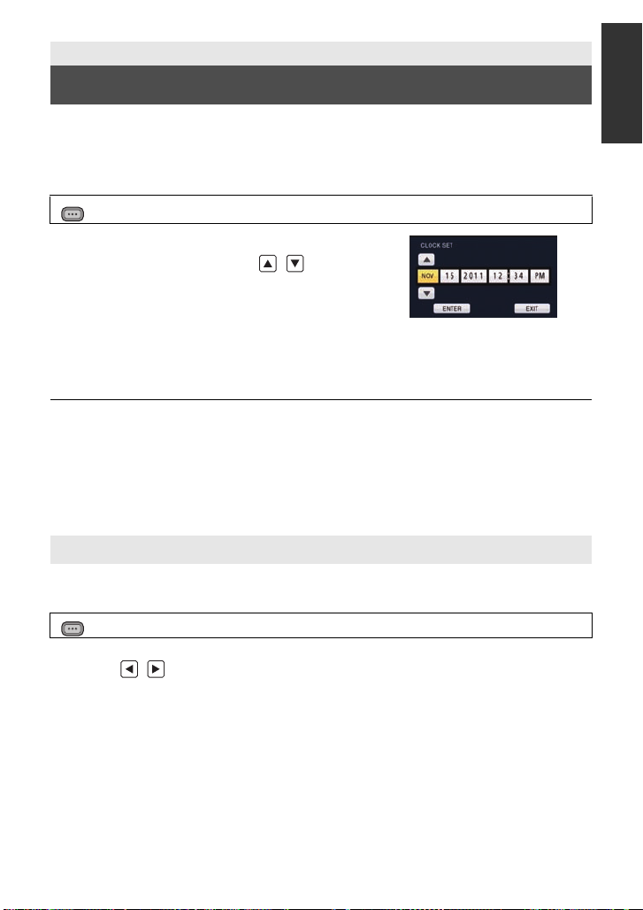
1 Select the menu. (l 30)
: [OTHER FUNCTION] # [CLOCK SET] # [YES]
2 Touch the date or time to be set, then set
the desired value using / .
≥ The year can be set between 2000 and 2039.
≥ The 12-hour system is used to display the time.
3 Touch [ENTER].
≥ The screen may switch to the setting screen for the [TIME ZONE]. Touch the screen and
set the [TIME ZONE].
≥ Touch [EXIT] to complete the setting.
≥ The date and time function is driven by a built-in lithium battery.
≥ If the time display becomes [- -], the built-in lithium battery needs to be charged. To
recharge the built-in lithium battery, connect the AC adaptor or attach the battery to this
unit. Leave the unit as it is for approx. 24hours and the battery will maintain the date and
time for approx. 6 months. (The battery is still being recharged even if the unit is off.)
≥ Display method of clock can be changed by setti ng the [DATE/TI ME] or [DATE FORMAT].
(l 124)
Time zone
Time difference from the Greenwich Mean Time can be set.
1 Select the menu. (l 30)
MENU
: [OTHER FUNCTION] # [TIME ZONE] # [YES]
≥ If the clock is not set, set the clock to current time first.
2 Touch
3 Touch [ENTER].
≥ Touch [EXIT] to complete the setting.
/ and set the region to record.
29
VQT3U98
Page 30
Preparation
MENU
MENU
Using the menu screen
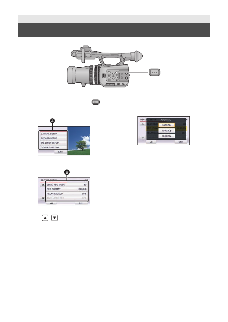
1 Press the MENU button .
2 Touch the top menu A.
3 Touch the submenu B.
≥ Next (Previous) page can be displayed by
touching / .
4 Touch the des ired item to e nter
the setting.
5 Touch [EXIT] to exit the menu
setting.
30
VQT3U98
Page 31

Preparation
MENU
SEARCH
STILL ADV STILL ADV
SEARCH
/VOL
DATE/TIME
START/
STOP
EXT DISPLAY
PLAY
STOP
OK
SKIP SKIP
MENU
PAUSE
2
3
4
6
5
8
7
9
10
11
1
Using with the wireless remote control
Select the menu.
: [OTHER FUNCTION] #
[REMOTE CONTROL] # [ON]
1 Power on/off button [ ]
The unit can be turned on/off when the
power switch of this unit is set to ON.
≥ It will not be possible to turn the unit on
with the wireless remote control
approximately 36 hours after turning the
unit off. To turn the unit on again, set the
power switch of this un it to OF F on ce, and
then to ON.
≥ Unit cannot be turned off when it is
connected to the PC.
2 Photoshot button [ ]
3 On-screen display button
[EXT DISPLAY] (l 89)
4 Playback operation buttons (l 80,
82)
These buttons function in the same manner
as the corresponding playback operation
icon being displayed on screen. [Excluding
Skip Playback (l 82)]
5 Delete button [ ] (l 87)
6 Direction buttons [3,4,2,1]
7 Zoom/volume/thumbnail display
8 Recording start/stop button [START/
switch buttons [T, W, /VOL]
*
STOP]
9 Date/time button [DATE/TIME] (l124)
10 Menu button [MENU]
*
11 OK button [OK] (l 32)
* means that these buttons function in the
same manner as the corresponding
buttons on the unit.
Remove the insulation sheet A before
using.
Replace a button-type battery
1 While pressing the stopper B, pull
out the battery holder.
2 Set the button-type battery with its
(i) mark facing upward and then
put the battery holder back in
*
*
place.
≥ When the button-type battery runs
down, replace it with a new battery
(part number: CR2025). The battery
should normally last about 1 ye ar,
however this depends on how
frequently the unit is use d.
≥ Keep the button-type battery out of
reach of children to prev ent
swallowing.
VQT3U98
31
Page 32

CAUTION
15
1515
1515
1515
STILL ADV STILL ADV
STOP
OK
SKIP SKIP
MENU
PAUSE
STILL ADV STILL ADV
STOP
OK
SKIP SKIP
MENU
PAUSE
Danger of explosion if battery is
incorrectly replaced. Replace only with
the same or equivalent type
recommended by the manufacturer.
Dispose of used batteries acco rding to
the manufacturer ’s instruction s.
Replace battery with Panasonic PART
NO. CR2025 only. Use of another battery
may present a risk of fire or explosion.
Caution: Battery may explode if mistreated.
Dispose of used battery promptly. Keep
away from chil dr e n.
Do not recharge, disassemble or dis pose
of in fire.
∫ Wireless remote control usable range
A Wireless remote control sensor
Distance: Within approx. 5 m (16 feet)
Angle: Approx. 15o up, down, left and right
≥ The wireless remote control is intended for indoor operation. Outdoors or under strong
light, the unit may not operate properly even within the usable ranges .
Operation of direction buttons/OK button
1 Press a direction button.
≥ Selected item will become yellow.
2 Select the item with the
direction button.
3 Confirm the selection by
pressing the OK button.
≥ Selection/confirmation of operation icons, thumbnail display etc. can be operated.
≥ Wherever you can touch with your finger can be operated by the wireless remote control.
(Excluding some functions)
32
VQT3U98
Page 33

Recording
Before recording
∫ Basic cam era positi oning
Normal recording
≥ Put your hand through the grip belt and
hold the unit with both hands.
Recording from a high position
Low-angle recording
≥ For easier low-angle recording, the sub
recording start/stop button and the sub
zoom lever can be used.
33
VQT3U98
Page 34

≥ When recording, make sure your footing is stab le and there is no danger of colliding with
MENU
another person or objec t.
≥ Hold the eye cup of the viewfinder as close as possible to your right eye.
≥ Adjust the angle of the LCD monitor according to the position in which the unit is he ld.
≥ When you are outdoors, record pictures with the sunlight behind you. If the subject is
backlit, it will become dark in the recording.
≥ Keep your arms near your body and separate your legs for better balance.
≥ For stable images, it is recommended to use a tr ipod whenever possible.
≥ Do not cover the cooling fan inlet with your hand etc.
Formatting cards
If you use the SD cards for the first time for recording with this unit, format the cards.
Please be aware that if a medium is formatted, then all the data recorded on the medium will
be erased and cannot be restored. Back up important data on a PC, disc etc. (l 93)
≥ When using two SD cards, format both SD cards.
1 Select the menu.
: [OTHER FUNCTION] # [FORMAT CARD]
2 Touch [SD CARD 1] or [SD CARD 2].
≥ When formatting is complete, touch [EXIT] to exit the message screen.
≥ Do not turn this unit off or remove the SD card, while formatting. Do not expose the unit to
vibrations or shock.
Use this un it to format media.
Do not format an SD card using any other equ ipment such as a PC. The card may
not be used on this unit.
34
VQT3U98
Page 35

Recording
MENU
Selecting a media to record
[SD CARD 1] and [SD CARD 2] can be selected separately to record motion pictures or still
pictures.
1 Select the menu.
: [SW & DISP SETUP] # [MEDIA SELECT] # [YES]
2 Touch the media to record motion
pictures or still pictures.
≥ The media is selected separately to motion pictures
or still pictures is highlighted in yellow.
3 Touch [ENTER].
35
VQT3U98
Page 36

Recording
3D video
A When you begin recording,
; changes to ¥.
B Mode switch
Recording motion pictures
You can record life-like and powerful 3D full hi gh definition quality video.
* The image is an illustration.
≥ This unit can record a 3D full high definition quality video in AVCHD 3D recording
format.
≥ Refer to page 91 for viewing 3D full high defini tion quality video with a 3D compatible TV.
≥ It is possible to record while checking the 3D video when the LCD monitor is used.
1 Change the mode to .
≥ Extract th e L C D mo n it or.
2 Select the menu.
MENU
: [RECORD SETUP] #
[3D/2D REC MODE] # desired setting
[3D]: Y ou can record with 3D Recording Mode.
[2D]: Y ou can record with 2D Recording Mode.
≥ appears when [3D/2D REC MODE] is set
to [3D].
3 Press the recording start/stop button
C to start recording.
≥ Recording is stopped if pressed the recording start/
stop button again.
36
VQT3U98
Page 37

∫ Screen indications in the Recording Mode
R 1h20mR 1h20mR 1h20m
TC 00:00:00:00TC 00:00:00:00TC 00:00:00:00
60 i60
i
2.92.92.9
R 1h20mR 1h20mR 1h20m
TC 00:00:00:00TC 00:00:00:00TC 00:00:00:00
60 i60
i
(When in 3D Recording Mode) (When in 2D Recording Mode)
TC 00:00:00:00 Counter display (l 63)
(White) Media where the motion picture is recor ded (l 35)
R1h20m Approximate remaining recordable time
*1
*2
60i Frame rate (l 115)
*1
C10
3D 2.9 - ¶ft
*1
*1 Only displayed when 3D Recording Mode is in use.
*2 Only displayed when 2D Recording Mode is in use.
≥ To rec ord effective image as a 3D, it is recommended t o adjust the convergence point as
necessary. (l 39)
≥ The default setting of [3D/2DREC MODE] is [3D].
≥ The images recorded between pressing the rec ording start/stop button to start recording
and pressing it again to pause recording become one scene.
≥ Up to approximately 3,900 scenes can be recorded on single SD card.
Number of scenes that can be recorded will be less than above in following cases:
jIf you change [3D/2D REC MODE] or [REC FORMAT]
jDuring the interval recording
jIf you change [MIC SETUP] or [AUDIOREC] (l 57, 58)
≥ Please refer to page 147 about approximate recordable time.
≥ When the remaining time is less than 1 minute, R 0h00m
flashes re d.
3D recording icon
Recording format (l 115)
Convergence point (l 39)
3D guide display (l 41)
37
VQT3U98
Page 38

To ensure that the 3D video can be safel y vi ewed, pay attentio n t o the fo ll o wing
points when recording.
≥ Do not get too close to the subject. (Use the 3D guide display as guidance. ( l 41))
* It is possible to get close to approximately 45 cm (1.5 feet) when the 3D macro is used.
(l 73)
≥ When moving the unit as you record, move it slowly.
≥ Try to hold the unit as steady as possible when recording while riding in a vehicle or
walking.
*
About the compatibility of the recorded motion pictures
≥ Please refer to page 115 about recording format.
When motion picture is recorded in A VCHD 3D format
≥ Only motion pictures recorded with the recording format set to AVCHD 3D are
supported by AVCHD 3D compatible equipment.
≥ It is still possible to play back when the motion picture is dub bed to an AVCHD
compatible equipment, but the 3D video recorded on this unit will be converted to a 2D
video. It is not possible to res tore the converted 2D video back to a 3D video.
≥ It is not always possible to play back motion pictures recorded with the recording
format set to AVCHD 3D on AVCHD 3D compatible equipment on AVCHD compatible
equipment. In such a case, play back on this unit instead.
When motion picture is recorded in AVCHD Progressive format
≥ Only motion pictures recorded with the rec ording format set to AVCHD Progressive are
supported by AVCHD Progressive compatible equipment.
≥ It is not always possible to play back motion pictures recorded with the recording
format set to AVCHD Progressive on AVCHD Progressive compatible equipment. In
such a case, play back on this unit instead.
When motion picture is recorded in A VCHD format
≥ Only motion pictures recorded with the recording format set to AVCHD are supported
by AVCHD compatible equipment. Images cannot be played with equipment that does
not support AVCHD (ordinary DVD recorders). Confirm that your equipment supports
AV CHD by ref erring to the operating instructions.
≥ It is not always possible to play back motion pictures recorded with the recording
format set to AVCHD on AVCHD compatible equipment. I n such a case, play back on
this unit instead.
38
VQT3U98
Page 39

Convergence point adjustment
A Convergence point
B Display in front of the screen
C Display behind the screen
* The image is an illustration.
MENU
∫ About the convergence point
Convergence point is a position that becomes the reference plane of the 3D image.
When viewing the 3D image, a subject located closer than the convergenc e point is
displayed in front of the screen, and a subject located farther t han the convergence point is
displayed behind the screen .
∫ Adjusting the convergence point
To ensure that the 3D imag e ca n be safely viewed , pay at te n t ion to the follow in g
points when adjusting the convergence point.
≥ The image may cause tiredness or discomfort when adju st ment of the convergence point
is frequently performed, or the posi ti on of the subjec t is furt her awa y in fron t or rear of the
convergence point or at the edge of the image.
≥ Stop the operation when you f eel fatigue, discomfort, or otherwise strange while
adjusting.
It is recommended to prepare for rec ording, such as adjust the convergence point in
accordance with the position of the subject in advance, determine the construction of the
image to record, etc., to re co rd an ima g e that is effective as 3D video. It is also
recommended to adjust the convergence point again when the distance between this unit
and the subject is changed si gnificantly .
1 Display the convergence.
: [SW & DISP SETUP] # [CONVERGENCE] # [ON]
39
VQT3U98
Page 40

2 Rotate the CONV. dial to adjust the
convergence point.
≥ This can be set between C00 and C99. Position of the
convergence point will be set further when the number
is larger.
≥ The subject at the position of the convergence point will
not shoot out or recess fro m the s creen. (It is seen as
same as the 2D image)
≥ Adjust by checking on the 3D image or 3D guide display
on the LCD monitor. (l 41)
≥ When zoo m i n g, it may be necess ar y to readjust the c o nvergence poi n t.
About Convergence Reset
When a convergence reset is perf ormed, the display of the convergence point goes to ,
and the convergence point is automatically set to prevent 3D video tha t tires or discomforts
the viewer . When the zoom magnification is changed, the convergence point is adjusted
automatically, so please use this setting y ou wish to re cord far away subj ects wit hout wo rrying
about convergence. (l 73)
≥ Optimal distance range for subject at Convergence Reset.
Zoom magnification
1k (Z00)
4k
(Z70)
8k
(Z92)
10k (Z99)
* This is the target when the [3D GUIDE] is set to [MODE1]. (l 41)
Optimal distance range between this unit and the
subject
approximately 0.9 m (3 feet) or further
approximately 3.4 m (11.2 feet) or further
approximately 6.7 m (22 feet) or further
approximately 8.3 m (27.2feet) or further
To adjust the convergence point with MIX display
Images from the left and right lenses are displayed overlapping when the 3D display is set to
MIX display. Adjust the convergence point so the outlines of the subject to be the reference
plane are ov er l a pp i ng exactly.
≥ The left and right images will not be perfectl y aligned if the subject is located at a distance
of less than approximately 45 cm (1.5feet).
≥ Please refer to page 72 for informati on on the 3D display.
CONV.
*
≥ 3D image can be recorded as close as approximately 45 cm (1.5 feet) from the lens when
the zoom magnification is set to 1k.
40
VQT3U98
Page 41

∫ 3D guide display
3D GUIDE
3D3D2.9 - 2.9 - ∞ ft ft3D2.9 - ∞ ft
2.9
3D GUIDE button
Press the button to switch on/off of the 3D
guide display.
A 3D guide dis pl a y
The 3D guide display is a guidelin e of dist ance between th e subj ect and t his unit to ef fecti vely
reproduce the subject as a 3D image.
≥ The values of the 3D guide display will change according to the zoom magnification and
convergence point settings.
To switch the screen size assumed for playback
It is possible to switch the range of the 3D guide display in accordance with the screen size
assumed for playback when the [3D GUIDE] is set.
≥ Set [3D/2D REC MODE] to [3D]. (l 36)
1 Select the menu.
MENU
: [SW & DISP SETUP] # [3D GUIDE] # desired setting
[MODE1]: When supposing the screen size to playback to be 77q or
[MODE2]: When the screen size for playback is assumed to be
≥ Color of the 3D in the 3D guide display will be as following.
j[MODE1]: 3D (White)
j[MODE2]: 3D (Green)
2 Touch [EXIT] to complete the setting.
smaller
approximately 200q
41
VQT3U98
Page 42

To record in such a way that 3D image of the subject can be effectively
2.9
reproduced
We recommend that you record with the subject positioned within the range of the 3D guide
display.
3D guide display
A Minimum di s ta nce on 3D guide di splay
B Maximum distance on 3D guide displ ay
≥ When the subject is out of the range of the 3D guide display, t he 3D guide display is
displayed in red. Move the uni t and change the position and angle of view with res pect to
the subject, adjust the con vergence dial so as to keep within the range of th e 3D guide
display.
≥ The 3D guide display may be displayed in red more when the [3D GUIDE] is set to
[MODE2].
≥ It may display duplicated, display strangely, or may not produce 3D image when the
subject that is at the distance out of the range for the 3D guide display is recorded.
42
VQT3U98
Page 43

∫ 3D Fine
The position, focus, and iris of the left and right lenses can be finely adjusted.
≥ Set [3D/2D REC MODE] to [3D]. (l 36)
≥ Connect this unit to the 3D compatible television using a HDMI cable (optional).
(l 88)
1 Select the menu.
MENU
: [OTHER FUNCTION] # [3D FINE] # [YES]
2 Touch the desired setting item to adjust.
[VERTICAL ALIGN]: The images from the left and right lenses are displayed
[FOCUS ADJUST]: Focus of the right len s can be finely adjusted. (l 44)
[IRIS ADJUST]: Iris of the right lens can be finely ad justed. (l 44)
≥ To adjust the [FOCUS ADJUST], set the Manual Focus Mode. (l 51)
overlapped and vertical position of the right lens can be
adjusted.
3 Touch [EXIT] to complete the setting.
≥ When distortion appears in the 3D video for a zoom operation after adjustment, readjust
the viewing angle.
≥ It will return to default setting in following cases:
jIf you turn the unit off
jIf you change [3D/2D REC MODE] or [REC FORMAT]
Vertical position adjustment
1 Touch / to adjust settings.
≥ It will return to default setting when [Reset] is touched.
2 Touch [ENTER].
43
VQT3U98
Page 44

Focus adjustment
A Lens switch icon
(When displaying image from the
right lens)
(When displaying image from the
right lens)
B Lens switch icon
1 Touch r/s to adjust the focus.
r: To focus on a close subjec t
s: To focus on a faraway subject
≥
It will return to default setting w hen [Reset] is touched.
≥ Focus Assist will operate when [FA] is touched, and
the part that is focused will be displayed in red.
Touch [FA] again to cancel the operation.
≥ Image of the left and right lenses will switch every
time the lens switch icon is touched.
≥
Adjusting the image from the left lens is not possible.
2 Touch [ENTER].
Iris adjustment
1 Touch r/s to adjust the brightness.
r: Brighten the image
s: Darken the image
≥
It will return to default setting w hen [Reset] is touched.
≥ Image of the left and right lenses will switch every
time the lens switch icon is touched.
≥
Adjusting the image from the left lens is not possible.
2 Touch [ENTER].
Utilizing the USER button
It is convenient to use following functions of the
USER button when 3D recording or adjusting the convergence point.
≥ Please refer to page 67 for details about setting the USER buttons.
USER button function Effect
R-image (l 72)
3D Display (l 72) Switches the display method of the 3D image.
Convergence Reset (l 73)
3D Macro (l 73)
Image displayed on the screen is switched to the image
from the right lens when the 3D display is turned off in
the 3D Recording Mode.
The display of the conver gence point goes to , and
the convergence point is automat ic ally set to pre ve nt 3D
video that tires or discomforts the viewer.
3D image can be recorded as close as approximately
45 cm (1.5 feet) to the subject when the zoom
magnification is set to 1k.
44
VQT3U98
Page 45

Recording
2.1
M
M
3
A Mode switch
R3000R3000R3000
2.1
M
Recording still pictures
3D still pictures and 2D still pictures in [ (1920k1080)] (16:9) are recorded for 3D
Recording Mode, and 2D still pictures in [ (2304k1296)] (16:9) are recorded for 2D
Recording Mode.
1 Change the mode to .
≥ Extract th e L C D mo n it or.
2 Press the button.
≥ Remaining number of recordable pictures is
displayed while still pictures are being
recorded.
∫ About the screen indications while recording still pictures
M
2.1
R3000 Remaining number of still pictures
Size of still pictures
Still picture indication
≥ 3D still pictures are recorded in MPO format, and 2D still pic tures in JPEG format.
≥ It is possible to record still pictures while recording motion pictures. (Simultaneous
recording)
≥ Using a tripod is recommended when recording still pictures in dark places because the
shutter speed becomes slow.
≥ If simultaneous recording is used while recording a motion picture, the remaining
recordable time will shorten. If the unit is turned off or the mode switch operated, the
remaining recordable time may length en.
≥ The 16:9 still pictures recorded using this unit may be c ropped at the edges when printed.
So, be sure to check before pr inting in the store or on your printer.
≥ Please refer to page 148 about approximate number of recordable pictures.
45
VQT3U98
Page 46

Recording
iA/MANU switch
Slide the switch to change the Intelligent
Auto Mode/Manual Mode.
MANU
MNL
Intelligent Auto Mode/Manual Mode
≥ is displayed in the Manual Mode.
≥ The following modes appropriate for the condition are set just by pointing the unit to what
you want to record in the Intelligent Auto Mode.
Mode Effect
Portrait Faces are detected an d focused automatically, and the brightn ess
Scenery The whole landscape will be recorded vividly without whiting out
Spotlight Very bright object is recorded clearly.
Low light It can record very clearly even in a dark room or twilight.
Normal In modes other than those described above, the contrast is
≥ Depending on the recording conditions, the unit may not enter the desired mode.
≥ In the Portrait, Spotlight, or Low Light Mode, the face will be surrounded by a white frame
when detected. In the Portrait Mode, a subject that is bigger and close to center of the
screen will be surrounded by an orange frame. (l 125)
≥ Faces cannot be detected depending on the recording conditions, such as wh en faces are
of certain sizes or at certain tilts or when digital zoom is used.
is adjusted so it is recorded clearly.
the background sky, which may be very bright.
adjusted to give a clear picture .
46
VQT3U98
Page 47

∫ Intelligent Auto Mode
4)
5)
6)
7)
8)
10 000K
9 000K
8 000K
7 000K
6 000K
5 000K
4 000K
3 000K
2 000K
2)
1)
3)
9)
When switching to Intelligent Auto Mode, the Auto White Balance and Auto Focus operate
and automatically adjust the color balance and focusing.
Depending on the brightness of the subject etc., the aperture and shut ter speed are
automatically adjusted for an optimum brightness.
≥ Color balance and focus may not be adjusted automatically depending on light sources or
scenes. If so, manually adjust these settings. (l 51, 52)
Automatic White Balance
The illustration shows the range over which Automatic White Balance functions.
1) The effective range of Automatic White Balance
adjustment on this unit
2) Blue sky
3) Cloudy sky (rain)
4) Sunlight
5) White fluorescent lamp
6) Halogen light bulb
7) Incandescent light bulb
8) Sunrise or sunset
9) Candlelight
If the Automatic White Balance is not functioning normally,
adjust the White Balance manually. (l 52)
Auto Focus
The unit focuses automatically.
≥ Auto Focus does not work correctly in the following
situations. Record picture s in t he Manual Focus Mode. (l 51)
jRecording distant and close-up objects at the same time
jRecording a subject behind dirty or dusty window
jRecording a subject that is surrounded by objects with glossy surfaces or by highly
reflective objects
47
VQT3U98
Page 48

Recording
Zoom lever/Sub zoom lever
T side:
Close-up recording (zoom in)
W side:
Wide-angle recording (zoom out)
TT
WW
WW
TT
WW
ABA
B
Zoom in/out function
It can be zoomed up to 10k for t he 3D Reco rding Mod e, an d up to 1 2k for th e 2 D Record ing
Mode.
≥ It can zoom up to 23k when the [i.Zoom] is set to [ON] du ring the 2D Recording Mode.
(l 118)
≥ Zoom magnification can be checked in the screen display of Z00 to Z99. The value gets
larger when zoomed in, and the value gets smaller when zoomed out. 99 is displayed
during the i.Zoom.
Ring zoom
Zoom operation can be done using the zoom ring.
Zoom ring A
Zoom by rotating the rin g .
A side:
Wide-angle recording (zoom out)
B side:
Close-up recording (zoom in)
48
VQT3U98
Page 49

∫ About the zoom speed
≥ The zoom speed will vary depending on how far the zoom leve r is pressed or how fast the
zoom ring is rotated.
≥ Zoom speed of the sub zoom lever will vary depending on the setting of [SUB ZOOM].
(l 126)
≥ The zoom speed does not vary when operating with th e wireless remote control.
≥ If you take your finger off the zoom lever during zoom operation, the operation sound may
be recorded. When returning t he zoom lever to the original position, move it quietly.
≥ It can be focused approximately 1 .2 m (3.9 feet) or further when the zoom magnification is
at its maximum.
≥ It can be focused approximately 30 cm (0.98feet) or further in 3D Recording Mode, and
approximately 3.5 cm (1 .4q) or further in 2D Record ing Mode when the zoom magnif ication
is set to 1k.
≥ The image may wiggle horizontally when zoomed dur ing the 3D Recording Mode. This is
because the convergence point is controlled in combination with the zoom. It does not
indicate a faul t .
≥ When switching to the [3D/2D REC MODE] setting, the zoom magnification will be set to
approximately 1k.
Utilizing the USER button
Digital zoom can be used by setting the USER button. (l 71)
≥ Please refer to page 67 for details about setting the USER button.
49
VQT3U98
Page 50

Recording
Optical image stabilizer button
Press the bu t t o n to turn optical im a g e stabilizer
on/off.
(3D Recording Mode)
# (setting c anceled)
(2D Recording Mode)
/ # (setting canceled)
≥ When [HYB R ID O.I .S .] is [ON], is
displayed. When [OFF], is displayed.
MENU
Image Stabilizer Function
Use the image stabilizer to reduce the effects of shake during recording.
This unit is equipped with Optical Image Stabilizer in the 3D Recording Mode.
This unit is equipped with Hybrid Optical Image Stabilizer in the 2D Recording Mode.
Hybrid Optical Image Stabilizer is a hybrid of optical and electrical image stabilizer.
O.I.S.
∫ Changing Image Stabilizer Mode
≥ Set [3D/2D REC MODE] to [2D]. (l 36)
: [RECORD SETUP] # [HYBRID O.I.S.] # [ON] or [OFF]
When set to [ON], you can further improve image stabilization for recording wh ile walking, or
holding the unit and recording a distant subject with zoom.
≥ This function’s default setting is [ON].
≥ This cannot be set when Optical Image Stabilizer is set to (setting canceled).
≥ Stabilization may not be possible under strong shaking conditions.
≥ When recording with a tripod, we recommend that you set the image stabilizer to
(setting canceled).
50
VQT3U98
Page 51

Recording
FOCUS A/M/
∞
A FOCUS A/M/¶ button
B Focus ring
Focus
Perform focus adjustments using the focus ring. If auto focus i ng is difficult due to the
conditions, then use Manual Focus.
≥ Switch to Manual Mode. (l 46)
1 Press the FOCUS A/M/¶ button to switch to Manual Focus.
≥ It will switch to MF from AF.
2 Adjust the focus by rotating the focus ring.
≥ The focus value can be set fr om MF0 0 (focus dist anc e: ap proxima tel y 30 c m (0.98feet) (in
3D Recording Mode) and approximately 3.5 cm (1.4 q) (in 2D Recording Mode)) to MF99
(focus distance: infinity). The larger the focus value gets, the further the position where
focus is achieved.
≥ It is set to MF95 and the focus will move to infinite when the FOCUS A/M/¶ butto n is
pressed and held.
≥ To return to Auto Focus, either press the FOCUS A/M/¶ button or set to Intelligent Auto
Mode by switching the iA/MANU switch.
≥ When the distance to the subject approaches within 1 m (3.3 feet) approx., the camera
switches to the macro range and or . (The camera may switch to the macro ran ge
even when the dista nce to the subject is 1 m (3.3 feet) or more dependin g on the subject.)
≥ Depending on the zoom magnification, this unit may fail to switch t o the macro ran ge, or go
to a non-displayed focus value.
≥ When you perform a zoom operation in the macro range, this unit may go out of focus.
≥ When you change the [3D/2DREC MODE] setting, this unit will go into Auto Focus Mode.
Utilizing the USER button
It is convenient to use following functions of the USER button when it is set to Manual Focus.
≥ Please refer to page 67 for details about setting the USER button.
USER button function Effect
Push AF (l 69)
Focus Assist (l 71) The in-focu s ar ea is displa y e d in red.
It can be temporary changed to Aut o Focus when it is
set to Manual Focus.
51
VQT3U98
Page 52

Recording
W.B.
A W.B. button
White Balance
Automatic White Balance function may not reproduce natural colors depending on the
scenes or lighting conditions. If so, you can adjust the White Balance manually.
Switch the modes of White Balance by pressing the W.B. button.
≥ Select the optimal mode by confirming the color on the scre en.
Icon Mode Settings
ATW
ATW Lock It will lock the setting for ATW.
*
P3.2k P reset value for studio recording (halogen lamp, etc.)
*
P5.6k P reset value for outdoors
*
Ach
*
Bch
* Only displayed when Manual Mode is in use.
≥ To return to auto setting, either set to ATW or set to Int elligent Auto Mode by switching the
iA/MANU switch.
≥ ATW and ATW Lock can also be set to the USER button. (l 67)
It will automatically adjust in accordance with the recording
condition.
Setting in accordance to the recording scenes can be set. (l 53)
≥ It is set to ATW when [3D/2DREC MODE] is set to [3D].
52
VQT3U98
Page 53

∫ To set the White Balance in accordance to the recording scene
Ach
Bch
MENU
1 Fill the screen with a whit e su bject.
2 Press the W.B. button to display Ach.
≥ When the operation icon is displayed and is touched, it will switch to . (l 78)
3 Keep on pressing the W.B. button to start the White Balance adjustment.
≥ The screen goes dark momentarily, “WB SET OK” is displayed, and the adjustment ends.
≥ When the mode of White Balance is set to something other t han Ach/Bch, the Black
Balance adjustment is performed by pressing and holding the W.B. button. Setting is
completed when the screen goes bl ack momentarily and “BB SET OK” is displayed.
≥ When the White Balance/Black Balance ca nnot be performed, an error message
“WB SET NG” or “BB SET NG” is displayed on the screen. In such case, use other mode.
≥ The contents previously set are maint ained in the Ach/Bch. Perfor m the settin g again when
the recording condition has chan ged.
∫ To finely adjust the White Balance
White Balance for the Ach/Bc h can be finely adjusted. Perform this af ter adjusting the White
Balance.
≥ Switch to Manual Mode. (l 46)
1 Select the menu.
: [CAMERA SETUP] # [COLOR TEMP A ch] or [COLOR TEMP B ch]
2 Touch / to adjust settings of color.
3 Touch [EXIT] to complete the setting.
53
VQT3U98
Page 54

Recording
IRIS A/M
MNL
F4.0
A Gain value
B Iris value
C Auto iris icon
*
* It is displayed in Auto Iris Mode.
1 IRIS A/M button
2 Iris ring
Iris adjustment
Perform Iris/Gain adjus tments using the iris ring.
Adjust it when the screen is to o bright or too dark.
≥ Switch to Manual Mode. (l 46)
1 Press the IRIS A/M button to switch to Manual Iris Mode.
≥ disapp ears.
≥ The gain is displayed in dB.
2 Adjust the iris by rotating the iris ring.
Iris/Gain value:
CLOSE
!#
≥ Value closer to CLOSE darken the image.
≥ Value closer to 30dB brighten the image.
≥ When the iris value is adjusted to brighter than OPEN, it changes to the gain value.
≥ To return to Auto Iris Mode, press the IRIS A/M button.
(F11 to F1.6) !# OPEN !# (0dB to 30dB)
≥ If the gain value is increased, the noise on the screen increases.
≥ Depending on the zoom magnification, there are iris values that are not displayed.
≥ When the [3D/2D REC MODE] setting is changed, th is unit goes into standard Auto Iris
Mode ( ).
54
VQT3U98
Page 55

∫ Adjusting brightness during the Auto Iris Mode
≥ Switch to Manual Mode. (l 46)
1 Select the menu.
MENU
: [CAMERA SETUP] # [AUTO IRIS LEVEL]
2 Touch / to adjust settings.
3 Touch [EXIT] to complete the setting.
Utilizing the USER button
It is convenient to use following functions of the USER button when it is set to Manual Iris.
≥ Please refer to page 67 for details about setting the USER button.
USER button function Effect
Backlight Compensation
(l 69)
Spotlight (l 70)
Switches to automatic iris control to compensate the
backlight. This will brighten the image on the screen to
prevent getting dar k when a backlight is hitting the
subject from the back .
Switches to automatic iris control for spotlight. This will
allow to clearly record an extreme ly bright subject.
55
VQT3U98
Page 56

Recording
SHTR
SHTR
Manual shutter speed
Adjust the shutter speed when recording fast-moving subjects.
≥ Switch to Manual Mode. (l 46)
1 Touch the LCD monitor to display the operation icons and touc h .
(l 78)
2 Touch / to adjust settings.
≥ When [AUTO] is touched, the shutter speed is set automatically.
≥ Touch to complete the adjustment.
Shutter speed:
1/60 to 1/2000
≥ It will be 1/30 to 1/2000 when [AUTO SLOW SHTR] is set to [ON]. (l 119)
≥ It will be 1/50 to 1/2000 (1/24 to 1/2000 when [AUTO SLOW SHTR] is set to [ON]) when
[REC FORMAT] is set to [1080/24p].
≥ The shutter speed closer to 1/2000 is faster.
≥ You may se e a band of ligh t aroun d an o bject th at i s shining v er y bright , or hi ghly reflec ti ve.
≥ During normal playback, image movement may not look smooth.
≥ If you record an extremely bright object or record under indoor lighting, color and screen
brightness may change or a horizontal line may appear on the screen. Perform following
operation in such case.
jRecord in the Intelligent Auto Mode
jAdjust the shutter speed to 1/60 in areas where the power supply frequency is 60 Hz, or
1/100 in areas of 50 Hz.
≥ When the [3D/2D REC MODE] setting is changed, the shutter speed is set automatically.
56
VQT3U98
Page 57

Recording
MENU
Audio Input
This unit can record audio in 5.1 ch or 2 ch.
When recording in 2 ch, it is possible to switch between built-in microphone, external
microphone, or connected audio equipment for each channel.
Microphone setup
Recording setting of the built-in mic rophone can be adjusted.
Select the menu.
: [RECORD SETUP] # [MIC SETUP] # desired setting
[SURROUND]: Sound is recorded with 5.1 ch surround microphone.
[ZOOM MIC]: Sound is recorde d with 5.1 ch surround microphone changing
[FOCUS MIC]: The forward sound is recorded more clearly by enhancing the
[2ch]: Sound from two directions is recorded in 2 ch by forward-facing
≥ If you wish to record higher quality sound and maintain realism even when zooming in, for
instance recording a music recital, we recommend setting [MIC SETUP] to [SURROUND].
≥ When [AUDIO REC] is set to [LPCM], [MIC SETUP] is set to [2ch], and t he setting cannot
be changed. (l 58)
≥ When the [BASS SETTING] is set to anything other than [0dB], it becomes impossible to
select [FOCUS MIC]. (l 121)
≥ Display of the audio level meter will change depending on the settings. (l 133)
the directionality in conjunction with the zoom operation.
Sounds near the front of the unit are recorded more clearly if
you zoom in (close-up) and surrounding sounds are recorded
more realistically if you zoom out (wide angle).
directionality toward the center for the 5.1 ch surround
microphone.
stereo microphones.
57
VQT3U98
Page 58

Audio recording
A CH1 switch
B CH2 switch
C INPUT1,2 (+48V) switches
D INPUT1,2 (LINE/MIC) switches
Switches the sound quality for the audio recording.
Select the menu.
MENU
: [RECORD SETUP] # [AUDIO REC] # desired setting
: Records in Dolby Digital.
[LPCM]: Records in uncompressed LPCM.
≥ It may not be able to play back on other devices when set to [LPCM].
≥ [AUDIO REC] will be set to when the [REC FORMAT] is set to [HA] or [HE], and the
setting cannot be changed.
Switching Audio Input
INPUT1
MIC
LINE
+48V
INPUT2
+48V
OFF ON
LINE
OFF ON
MIC
INT(L
INPUT1
INPUT2
(R)
INT
INPUT2
CH1
)
CH2
∫ Using the built-in microphone
Audio is recorded with the built-in microphone (5.1 ch) when the [MIC SETUP] is set to
anything other than [2ch] .
When [MIC SETUP] is set to [ 2ch], aud io is recorded with th e built-in mic rophon e (2 ch) when
the CH1 switch is set to INT(L) and the CH2 switch is set to INT(R).
58
VQT3U98
Page 59

∫ Using an external microphone or audio equipment
A AUDIO INPUT2
terminal (XLR 3 pin)
B AUDIO INPUT1
terminal (XLR 3 pin)
≥ Set [MIC SETUP] to [2ch]. (l 57)
1 Connect an external microphone or audio
equipment to AUDIO INPUT1,2 terminals
(XLR 3 pin). (l 15)
2 Use INPUT1,2 (LINE/MIC) switches to
switch the connected audio input signal.
LINE: audio equipment is connected
Input level is 0 dBu.
MIC: an external microphone is connect ed
Input level is -50 dBu.
≥ When [EXT. MIC GAIN1] or [EXT .MIC GAIN2] is set to
[-60dB], the input level is set to -60 dBu. (l 121)
3 (When using the phantom microphone (which
requires +48 V power supply))
Set the INPUT1,2 (+48V) switches to ON.
ON: +48 V power supply to audio input terminals 1, 2 (XLR 3 pin).
OFF: No power supply for audio input terminals 1, 2 (XLR 3 pin).
4 Use the CH1 switch to select the input signal to be recorded to audio
channel 1.
INT(L): Au dio from the built-in microphone L (left) ch is recorded to audio channel 1.
INPUT1: Audio from a device connected to audio input terminal 1 (XLR 3 pin) is recorded to
channel 1.
INPUT2: Audio from a device connected to audio input terminal 2 (XLR 3 pin) is recorded to
channel 1.
5 Use the CH2 switch to select the input signal to be recorded to audio
channel 2.
INT(R): Audio from the built-in microphone R (right) ch is recorded to audio channel 2.
INPUT2: Audio from a device connected to audio input terminal 2 (XLR 3 pin) is recorded to
channel 2.
59
VQT3U98
Page 60

To remove the external microphone, etc., from the audio input terminals 1, 2
ヱヶヴラ
A PUSH section
(XLR 3 pin)
Remove while pushing on the PUSH section of t he audio
input terminals 1, 2 (XLR 3 pin).
≥ Set the input signal to buil t-in mic rophon e by switc hing
the CH1, CH2 switche s to IN T (L ) or IN T (R) afte r
removing the external microphone. Audio will not be
recorded when motion picture is recorded without
switching.
≥ Set INPUT1,2 (+48V) switches to OFF if you connect equipment not compatible with
+48 V. You can damage this unit or such equipment if you leave the setting at ON.
≥ This unit is turned off when a problem occurs with the +48 V power supply.
≥ The battery will discharge faster if you use a phantom microphone.
≥ When inputting the external microphone signal to audio channels 1 and 2, connect the
external microphone to audi o i nput2 terminal (XLR 3 pin) and switch both CH1 and CH2
switches to INPUT2.
60
VQT3U98
Page 61

Adjusting the audio input level
MENU
A Center
B Front left
C Back left
D Front right
E Back right
F Microphone input level
∫ Adjusting the input level of the built-in microphone (5.1 ch)
≥ Set the [MIC SETUP] to anything other than [2ch]. (l 57)
1 Select the menu.
: [RECORD SETUP] # [5.1ch MIC LEVEL] # desired setting
[AUTO]: ALC is activated, and the recording level is adjusted
[SET]/[SETr ]: The desired recording level can be set.
automatically.
2 (When [SET]/[SETr ] is selected)
Touch / to adjust the microphone
input level.
≥ Touch to activate/disactivate ALC. When ALC is
activated, the icon is surrounded by yellow and the
amount of sound distortion can be reduced. When
ALC is disactivated, natural recordin g ca n be
performed.
≥ Adjust the microphone input level so that the last
2 bars of the gain value are not red. (Otherwise, the
sound is distorted.) Select a lower setting for
microphone input level.
3 Touch [ENTER] to set the microphone
input level and then touch [EXIT].
≥ is displayed on the recording screen when the ALC is turned on.
≥ When [MIC SETUP] is [ZOOM MIC], the volume will be different depending on the zoom
rate.
≥ You cannot record with the audio completely muted.
61
VQT3U98
Page 62

Adjusting the input level of the built-in microphone (5.1 ch) using the operation
A Audio control knobs (CH1, CH2)
B Audio level meter
C -12 dB
D 0 dB
icons
≥ Set the [MIC SETUP] to anything other than [2ch]. (l 57)
≥ Set [5.1ch MIC LEVEL] to [SET]/[SETr ]. (l 61)
1 Display the operation icons and touch . (l 78)
2 Touch / to adjust settings.
3 Touch to complete the setting.
∫ Adjusting the input level of the built-in microphone (2 ch), external
microphone or audio device
≥ Set [MIC SETUP] to [2ch]. (l 57)
Adjust the input level operating the Audio control knobs (CH1, CH2)
CH1
CH2
≥ Adjust confirming the audio level meter.
62
VQT3U98
Page 63

Recording
COUNTER
COUNTER button
Each time you press the button, the counter
display changes.
Time Code # User Information # Recording
Counter # Setting canceled
Counter display
You can change a counter display that indicates how much time has elapsed during
recording or playback.
Counter display Indications
Time Code
User Information (l 65) UB 00 00 00 00
Recording Counter (l 66)
TC 00:00:00:00 or TC 00:00:00.00
≥ Display will change depending on the setting of the
[TC MODE]. (l 64)
(In Recording Mode)
00:00:00 or SCN 00:00:00
(In Playback Mode)
SCN 00:00:00
≥ In Recording Mode, display will change depending on
the setting of the [RECCOUNTER]. (l 66)
≥ In Playback Mode, display will return to SCN 00:0 0: 00
for each scene.
63
VQT3U98
Page 64

Setting the Time Code
MENU
Time code will display the recording time in hours, minutes, seconds, and frames.
TC 00:00:00:00 (hour : minute : second : frame [NDF])
TC 00:00:00.00 (hour : minute : second . frame [DF])
≥ The frame (Number of frames counted every second ) wil l vary depending on the
[REC FORMAT] setting. (l 115)
Recording format Frame
[1080/60p], [1080/60i], [1080/30p], [PH], [HA], [HE] 0 to 29
[1080/24p] 0 to 23
[TC MODE]
Select the compensation mode for the time code.
MENU
: [RECORD SETUP] # [TC MODE] # desired setting
[DF]: Time code is compensa ted in ac cordanc e with th e actual time. It
[NDF]: It will not compensate the time code. (There will be a difference
≥ It is automatically set to [NDF ] whe n the [RECFORMAT] is set to [1080/24p ] or t he interv al
recording is used.
is mainly used for broadcasti ng such as TV programs.
from the actual ti m e )
[TCG]
Sets the way the time code will move.
: [RECORD SETUP] # [T C G] # desired setting
[FREE RUN]*: It will constantly move.
[REC RUN]: It will move only when reco rding.
* An error may occur when the playback mode is switched when the [REC FORMAT] is set
to [1080/24p].
≥ It is automatically set to [FREE RUN] when it is set to PRE-REC.
≥ The time code will reset when the built-in lithium battery is exhausted when it is set to
[FREE RUN].
64
VQT3U98
Page 65

[TC PRESET]
Y ou can set the initial time code.
1 Select the menu.
MENU
: [RECORD SETUP] # [TC PRESET] # [YES]
2 Touch the item to set and change with / .
≥ It will be set to 00h00m00s00f when the RESET button is pressed.
≥ “h” is an abbreviation for hour, “m” for minute, “s” for second and “f” for frame.
3 Touch [ENTER].
≥ Touch [EXIT] to complete the setting.
≥ This unit will adjust the time code in accordance with t he frame r ate of t he recording format.
(l 115) Theref ore, it may not be continuous from the previous final time code when the
recording format is changed.
≥ Set the frame to [00] or value that is multiple of 4 when the [REC FORMAT] is set to [1080/
24p]. The time code that is recorded will shift when other values are set.
Setting the User Information
Eight digit hexadecimal alphanumeric can be entered and displayed as a memo information
such as dates, control numbers, etc., into the User Information .
UB 00 00 00 00
[UB PRESET]
You can set the User Informati on .
1 Select the menu.
MENU
: [RECORD SETUP] # [UB PRESET] # [YES]
2 Touch the item to set and change with / .
≥ You can use numbers from 0 to 9 and letters from A to F.
≥ It will be set to 00 00 00 00 when the RESET button is pressed.
3 Touch [ENTER].
≥ Touch [EXIT] to complete the setting.
65
VQT3U98
Page 66

Setting the Recording Counter
Recording Counter will display the recording time in seconds.
00:00:00 (hour : minute : second (When [REC COUNTER] is set to [TOTAL]))
SCN 00:00:00 (hour : minute : second (When [REC COUNTER] is set to [SCENE]))
[REC COUNTER]
Select the counting method during the recording.
MENU
: [SW & DISP SETUP] # [REC COUNTER] # desired setting
[TOTAL]: The count continues to increase until the Recording Counter is
[SCENE]: Resets t he Recording Counter at start of recording. Counts the
resetted.
time of each recording session.
To reset the Recording Counter for the Recording Mode
The Recording Counter will be set to 00:00:00 when the RESET button is presse d while
displaying the counter.
66
VQT3U98
Page 67

Recording
MENU
A USER1 button
B USER2 button
C USER3 button
D USER4 button
E USER5 button
F USER6 button
G USER7 button
USER button
Each of the USER button can regis ter one function from the 18 available f unctions.
≥ There are three USER buttons (USER1 to USER3) on the main body and four USER
button icons (USER4 to USER7) displayed on the LCD monitor.
Setting the USER button
1 Select the menu.
: [SW & DISP SETUP] # [USER BUTTON SETUP]
2 Touch the USER button you wish to set.
≥ The USER button number and currently set function name are displayed. (For example, a
display of 1. [FA] means that Focus Assist has been assigned to USER1 button.)
3 Touch the item to register.
≥ For the functions of the USER button that can be registered, refer to page 69.
≥ Touch [INH] (Inhibit) if not registering.
≥ Next (Previous) page can be displayed by touching / .
≥ To co ntinuously set other USER buttons, repeat steps 2-3.
4 Touch [EXIT] to complete the setting.
≥ There are some functions that cannot be used depending on the position of the mode
switch. (l 69)
≥ Setting will be common for the recording mode and the playback mode.
67
VQT3U98
Page 68

Using the USER button
USER1 USER2 USER3
(In Recording Mode)
Conv.R
3D
REC.C
ATW
USER4
USER5
USER7
USER6
(In Playback Mode)
DISP/MODE CHK
To use the set USER button, press USER1 to USER3 button or touch the USER4 to USER7
button icon displayed whe n you touch the LCD monitor .
(When you use the USER1 to USER3) (When you use the USER4 to USER7)
USER4
USER5
USER6
USER7
SCN1 SCN2 SCN3 SCN4 SCN5 SCN6
ATW
Conv.R
3D
REC.C
≥ To cancel, press the USER button or touch the USER button icon again.
For canceling or using of the fo llowing functions for the USER buttons, refer to each page.
jPush AF (l 69)
jBlack Fade (l 70)
jWhite Fade (l 70)
jDigital Zoom (l 71)
j3D Display (l 72)
jRecording Check (l 73)
jLast Scene Delete (l 74)
j3D video output selection (l 74)
jPlayback parallax adjustment (l 71)
∫ Switch display/not-display of the USER buttons
Display/n ot-display of th e U S ER bu tton icons in th e LCD monitor can be switched.
MENU
: [SW & DISP SETUP] # [USER BUTTON DISPLAY] # [ON] or [OFF]
∫ Check the setting of the USER buttons
To check the settings of the USER buttons
(USER1 to USER3) in the recording screen,
press and hold on the DISP/MODE CHK
button.
68
VQT3U98
Page 69

Functions of the USER button
∫ List of USER button function
Icon Item Function
*1
[P.AF]
[B.Light]
[S.Light]
[B.FD]
[W.FD]
[ATW]
[ATW.L]
[FA]
[D.ZM]
[PARA]
[HIST]
[3D] [3D] 3D Display
[R-Img]
[MACR]
[Conv.R]
[REC.C]
[LstDel]
[3D o/p] [3D OUTPUT] 3D video output selection
*1 It is no t po ss ib le to use in Pl ay b ac k Mo d e.
*2 It is not possible to use in Recording Mode.
[PUSH AF] Push AF
*1
[BACKLIGHT] Backlight Compensation
*1
[SPOTLIGHT] Spotlight
*1
[BLACK FADE] Black Fade
*1
[WHITE FADE] White Fade
*1
[ATW] ATW
*1
[ATW LOCK] ATW Lock
*1
[FA] Focus Assist
*1
[D.ZOOM] Digital Zoom
*2
[PA R ALLAX] Playback parallax adjustment
*1
[HISTOGRAM] Histogram
*1
[R-IMAGE] R-image
*1
[3D MACRO] 3D Macro
*1
[CONV.RESET] Convergence Reset
*1
[REC CHECK] Recording Check
*1
[LAST SCN DEL] Last Scene Delete
Push AF
It can be temporary changed to Aut o F ocus when it is set to Manual Focus. (l 51)
Press and hold the USER button, or touch and hold the USER button icon in the
recording screen.
≥ It will be canceled when the button is released.
≥ The focus position set by the Push AF will be maintained when canceled.
Backlight Compensation
Switches to automatic iris control to compensate the backlight.
This makes the image brighter to prevent darkening of a backlit subject.
≥ appears when it is set.
≥ It will return to standard Auto Iris Mode ( ) when it is canceled. (l 54)
69
VQT3U98
Page 70

Spotlight
Switches to automatic iris control for spotlight.
Very bright object is recorded clearly.
≥ appears when it is set.
≥ It will return to standard Auto Iris Mode ( ) when it is canceled. (l 54)
Black Fade
Fade in/fade out eff ect (black) can be added to the video an d audio that is being recorded.
Press USER button or touch USER button icon in the recording screen.
≥ Fade out will start, and fade in will start after complet i ng the fade out.
≥ It will fade out when the button is pressed and held, and fade in will start when the button is
released.
≥ This effect cannot be set for interval recording, or when 3D display is set to MIX display.
(l 72)
≥ The thumbnails of scenes recorded using fade in be co me black.
White Fade
Fade in/fade out eff ect (white) can be added to the video and audio that is being recorded.
Press USER button or touch USER button icon in the recording screen.
≥ Fade out will start, and fade in will start after complet i ng the fade out.
≥ It will fade out when the button is pressed and held, and fade in will start when the button is
released.
≥ This effect cannot be set for interval recording, or when 3D display is set to MIX display.
(l 72)
≥ The thumbnails of scenes recorded using fade in beco me white.
ATW
The White Balance can be changed to ATW. (l 52)
≥ This cannot be set when the Intelligent Auto Mode is used or the White Balance is set to
ATW Lock.
70
VQT3U98
Page 71

A TW Lock
The White Balance can be changed to ATW Lock. (l 52)
≥ It will return to ATW when canceled.
≥ This cannot be set when the White Balance is set to anything other than ATW.
Focus Assist
The in-focus area is displayed in red.
≥ The red display does not appear on the images actually recorded.
≥ The red display does not appear on TV.
Digital Zoom
Press USER button or touch USER button icon in the recording screen.
≥ Set [3D/2D REC MODE] to [2D]. (l 36)
≥ The zoom magnification will change every time the button is pressed or the button icon is
touched.
2k # 5k # 10k # Setting canceled
≥ The larger the digital zoom magnificati on, the more the image quality is degraded.
≥ Digital zoom is not possible when the [RECFORMAT] is [1080/24p].
≥ Digital zoom is canceled in following cases:
jIf you turn the unit off
jIf you use the Quick Start Mode (l 75)
jIf you change the mode
Playback parallax adjustment
It is possible to adjust the parallax of the scene recorded in 3D during the Pl ayback Mode.
≥ Change the mode to and touch the play mode select icon.
Then, set [VIDEO/PICTURE] to [3D]. (l 79)
1 Pause during the playback of the scene recorded in 3D.
2 Press USER button or touch US ER button icon .
3 Touch / to adjust settings.
4 Press the USER button or touch the USER button icon again to end the
setting.
≥ The setting is canceled in following cases:
jIf you stop playback
jIf you turn the unit off
jIf you change the mode
≥ Stop the operation when you feel fatigue, discomfort, or otherwise strange while
playing back or adjusting.
VQT3U98
71
Page 72

Histogram
3D
A graph with brightnes s a s horizontal axis and number of pixels at that brightness as v ertical
axis is displayed. It is possi ble to determine the exposure of the whole image by looking at
the distribution in the graph.
≥ To adjust the brightness, refer to page 54.
3D Display
Switches the display method of the 3D v ideo.
≥ These settings will not affect the actual images recorded.
≥ Set [3D/2D REC MODE] to [3D]. (l 36)
Press USER button or touch USER button icon.
≥ It will switch every time the button is pressed or the button icon is touched.
3D Display # MIX Display # 3D Display off
3D Display: 3D video is displayed. is displayed.
MIX Display: The images of the left and right lense s are di splayed overl apped
3D Display off: The image from the left lens is only displayed.
and is displayed.
∫ To change to 3D display when in the Playback Mode
≥ Change the mode to and touch the play mode select icon.
Then, set [VIDEO/PICTURE] to [3D] or [PICTURE]. (l 79)
1 Play back the scene or still picture recorded in 3D.
≥ It is convenient to use Pause.
2 Press USER button or touch US ER button icon .
≥ It will switch every time the button is pressed or the button icon is touched.
3D Display # 3D Display off
≥ This cannot be set when [3D OUTPUT] is set to [HDMI]. (l 74, 92)
R-image
Image displayed on the scr een is switched to the image from the r i ght lens when the 3D
display is turned off in the 3D Recording Mode. is displayed when displaying the video
from the right lens.
≥ Set [3D/2D REC MODE] to [3D]. (l 36)
≥ Set the 3D Display to off.
≥ The image displayed on the TV will not switch to the image from the right lens even if the
R-Image is set while the TV is connected.
72
VQT3U98
Page 73

3D Macro
3D image can be recorded as close as approximately 45 cm (1.5 feet) to the subject when
the zoom magnification is set to 1k.
≥ Set [3D/2D REC MODE] to [3D]. (l 36)
≥ is displayed.
≥ Canceling returns the convergence point to the original position.
≥ The setting is canceled in following cases:
jIf you adjust the CONV. dial (l 40)
jIf you perform the convergence reset
≥ Stop the recording when you feel fatigue, discomfort, or otherwise strange while
recording.
Convergence Reset
The display of the converg ence point goes to , and the convergence po int is aut omatica lly
set to prevent 3D video that tires or discomforts the viewer.
≥ When the zoom magnification is changed, the conv ergence po int is adjus ted automa tica lly,
so please use this setting you wish to record faraway subjects without worrying about
convergence.
≥ The setting is canceled in following cases:
jIf you adjust the CONV. dial (l 40)
jIf you use the 3D Macro
Recording Check
Approximately 2 seconds at the end of the video recorded last can be played back. It will
return to recording screen once the playback is completed.
≥ Playback operation is not possible during the Recording Check.
≥ Recording Check is not possible in following cases:
jWhen the un i t i s tur n ed on /o ff
jWhen the mode switch is operated
jWhen the setting of [3D/2D REC MODE] or [REC FORMAT] is changed
jWhen the SD C a rd is i nserted/rem o ved
jDuring the interval recording
73
VQT3U98
Page 74

Last Scene Delete
The motion picture recorded last can be deleted.
Deleted scenes cannot be restored.
1 Press USER butt on or touch USE R butto n icon in the recording screen.
2 Touch [YES].
≥ It will return to recording screen without deleting by touching [NO].
≥ Last Scene Delete is not possible in following cases:
jWhen power is turned on/off
jWhen the mode switch is operated
jWhen the setting of [3D/2D REC MODE] or [REC FORMAT] is changed
jWhen the SD C a rd is i nserted/rem o ved
jDuring the interval recording
3D video ou tput selection
It is possible to switch the dest i nation of the 3D full high definition quality video output when
this unit is connected with the 3D compatible television that is compatib le with the frame
sequential format using a HDMI cable (optional).
≥ Set [3D/2D REC MODE] to [3D]. (l 36)
Press USER button or touch USER button icon.
≥ It will switch every time the button is pressed or the button icon is touched. (Black screen is
displayed for few seconds.)
LCD # HDMI
LCD: 3D video is displayed on the LCD monitor of this unit and the 3D
HDMI: Displays 3D full high definition image on the 3D-compatible TV.
compatible TV. (The 3D video displayed on the TV will be a 3D
video in side-by-side format, and the picture quality will be
different from the 3D full high definition video.)
(2D image is displayed on the LCD monitor of this unit.)
∫ To change the 3D video output selection when in the Playback Mode
≥ Change the mode to and touch the play mode select icon.
Then, set [VIDEO/PICTURE] to [3D]. (l 79)
With the playback paused, press USER button or touch USER button icon.
≥ It is also possible to set with the menu. (l 92)
≥ This cannot be set during recording or playback.
≥ If the TV used is not compatible with the frame sequential format, th e picture quality will not
be of 3D full high definition v i deo even if it is set to HDMI.
74
VQT3U98
Page 75

Recording
ZEBRA
BARS
DISP/MODE CHK
QUICK START
A DISP/MODE CHK button
B ZEBRA button
C QUICK START button
D BARS button
Useful functions
Quick Start
1 Press and hold down the QUICK START
button until the display on the LCD monitor/
viewfinder disappears.
The quick start lamp E flashes green and the unit goes
into Quick Start Standby Mode.
2 Press the QUICK START button.
The quick start lamp E goes off and the unit is put into
recording pause about 0.6 seconds.
≥ When in Quick Start Standby Mode about 70% of the power used in recording pause
mode is being consumed, so the recording time will be reduced.
≥ This unit is turned off after approxi mately 30 minutes elapse in Quick Start Standby Mode.
≥ Quick Start Standby Mode is cleared when the mode switch is set to .
≥ Depending on the recording conditions and men u settings, time for Quick Start may be
longer than 0.6 seconds.
≥ It may take some time for Automatic White Balance to adjust.
≥ In the Quick Start Mod e, the zoom magnification becomes 1k.
75
VQT3U98
Page 76

Zebra
ZEBRA button
It will switch between the zebra dis play and the marker display every time the button is
pressed.
Zebra 1 # Zebra 2
* It is not displayed when the [ZEBRA DETECT 2]/[MARKER] is set to [OFF]. (l 123)
Zebra display:
Parts where white saturat ion (color sat uration ) is likel y to occu r (extreme ly brig ht ly lit or s hi ny
parts) are displayed with diagonal lines (zebra pattern).
Marker display:
Displays the luminance level of the center of the screen (luminance display frame) in %.
It makes the adjustment of the brightness of the object easier, by checking the luminance
level of the object, when recording same object in different surroundings.
≥ Marker display is displayed between 0% and 99%. It will be displayed as 99% when it is
over 99%.
≥ You can record an image with little white saturation if you manually adjust the shutter
speed or brightness. (l 54, 56)
≥ The zebra pattern does not appear on the images actually recorded.
≥ It is also possible to adjust the level of the zebra pattern to be displayed. (l 122)
*
# Marker* # setting canceled
Color Bar Screen
BARS button
Press the BARS button to output a color bar screen to a television or monitor so you can
adjust them.
≥ To cancel, press the BARS button again.
≥ It will be canceled when the unit is turned off.
≥ While the color bar is displayed, a test tone will be output from the headphone terminal,
HDMI terminal and AV mul ti terminal. (The test tone that is output will be 1 kHz.) It will not
be output from the speaker of this unit.
≥ It is possible to record the color bar screen.
76
VQT3U98
Page 77

Switching the screen indications/mode information display
DISP/MODE CHK button
All the screen display other than the Counter display, Recording start/st op, Zebra display ,
Marker, and Safety Zone will disappear when this button is pressed. (l 132)
≥ To cancel, press the DISP/MODE CHK button again.
∫ To display the Mode Information
List of functions assi gned to the USER buttons (USER1 to USER3) and se ttings of the
[SUB REC BUTTON] and [SUB ZOOM] are displayed by pressing and holding the DISP/
MODE CHK button.
≥ They are displayed only while the DISP/MODE CHK button is held. It is disappeare d when
the button is released.
77
VQT3U98
Page 78

Recording
SCN1 SCN2 SCN3 SCN4 SCN5 SCN6
SHTR
Ach
Conv.R
3D
REC.C
ATW
ATW
Conv.R
Ach
Bch
SHTR
Using of Operation Icons
You can use convenient functions just by the easy operation of touching the sc r een.
1 Touch the LCD monitor in the recording
screen or playback screen.
≥ The operation ic ons are displ aye d.
2 Touch an operation icon.
≥ The following function is availabl e. Refer to the
respective pages for the operation.
, etc. Customize Scene (l 110)
SCN1 SCN2
, etc. USER Button Icon (l 67)
, White Balance (l 52)
Shutter Speed Adjustment (l 56)
Headphone Volume Adjustment
5.1 ch Microphone Level (l 62)
*1 It is not displayed in the Playback Mode.
*2 It is not displayed in the Intelligent Auto Mode.
*3 It is displayed only when connected to the headpho ne terminal.
≥ If you touch the screen while an operation icon is being displayed or do not touch the icon
for a certain period, it will disap pear. To display again, touch the screen.
∫ Headphone Volume Adjustment
Adjust the volume of the head phone while recording.
1 Display the op eration icons and touch .
2 Touch / to adjust the volume.
≥ Actual volume to be recorded does not chang e.
3 Touch to exit the setting.
*1, 2
*1, 2
*1, 2
*1, 3
*1
78
VQT3U98
Page 79

Playback
111222333
444555
666
777888999
2D
111222333
444555
666
777888999
3D
Conv.R
3D
REC.C
ATW
TCTC
00:00:00:00 00:00:00:00
TC
00:00:00:00
Motion picture/Still picture playback
1 Change the mode to .
2 Touch the play mode select icon A.
3 Select the [MEDIA] and [VIDEO/
PICTURE] you wish to play back.
≥ Touc h [ENTER].
≥ An icon is displayed in the thumbnail display when
video item is touched. ( ,
)
4 Touch the scene or the still picture to be
played back.
≥ The recording format of the se lected scen e is di splayed in t he
thumbnail display of the motion pictures. ( , ,
etc.)
≥ is displayed on the 3D still picture in the thumbnail
display of the still pictures.
≥ Next (Previous) page can be displayed by touching / .
5 Select the playback operation by touching the operation icon.
B Operation icon
≥ If you touch the screen while an ope rat ion icon is be ing
displayed or do not touch the icon for a c ertain period, it
will disappear. To display again, touch the screen.
123
45
789
123
45
789
6
6
VQT3U98
79
Page 80

Motion picture playback Still picture pl ayback
TT
WW
WW
TT
WW
WWWW
W
1/;: Playback/Pause
6: Rewind playback
5: Fast forward playback
∫: Stops the playback and shows
the thumbnails.
: Display the direct playback bar
(l 83)
1/;: Slide sh ow (playback of the still
pictures in numerical order) start/
pause.
2;: Plays back the previous picture.
;1: Plays back the next picture.
∫: Stops the playback and shows
the thumb n a i ls.
∫ Change the thumbnail display
While the thumbnail is displayed, the thumbnail display
changes in the following order if the zoom lever or the sub
zoom lever is operated to side or side.
( side) ( side)
20 scenes () 9 scenes () 1 scene () Scene information display
*
* Detailed information of the scene is displayed when playing back motion pictures.
Following information is displayed.
jStart TC
jStart UB
jDate
jTim e zon e
jRecording time
jFormat
≥ 9 scenes display returns if the unit is turned off or the mode is changed.
≥ By displaying in 1 scene, recording date and time ar e displayed when playing back motion
pictures, and recording date and file number when playing back still pictures.
∫ Speaker/Headphone volume adjustment
Operate the volume lever or the
sub zoom lever to adjust the
speaker/headphone v ol ume durin g
Motion Picture Playbac k Mode.
Towards “r”:
Increases the volume
Towards “s”:
Decreases the volume
TTT
W
W
TTT
W
W
≥ To play back the scenes or still pictures recorded in 3D as 2D, set the 3D Display to off.
(l 72)
≥ Sound will be heard only during normal playback.
≥ If pause play is continued for 5 minutes, the screen returns to the thumbnails.
≥ At playback of scenes recorded in 2D, the screen goes dark momentarily when switching
between scenes recorded us ing [1080/60p] and other scenes.
pictures.
≥ The screen goes dark momentarily when switching between 3D still pictures and 2D still
80
VQT3U98
Page 81

Motion picture compatibility
≥ This unit is based on AVCHD 3D/AVCHD Progressive/AVCHD.
AVCHD 3D video
≥ Video signals for the AVCHD 3D that can be played back with this unit are 1920k1080/
60i and 1920k1080/24p.
≥ Do not delete or edit the 3D video recorded on the SD card with this unit using
anything other than AVCHD 3D compatible equipment (such as conventional
AVCHD compatible equipment). 3D video in the SD card will be converted to 2D
video. Once it is converted to 2D video, it is not possible to restore to 3D video.
≥ This unit may degrade or not play back motion pictures recorded or created on other
products, and oth er products may degrade or not play back motion pictures recorded
on this unit, even if the products support AVCHD 3D.
AVCHDProgressive video
≥ Video signal for the AVCHD Progressive that can be played back with this unit is
1920k1080/60p.
≥ This unit may degrade or not play back motion pictures recorded or created on other
products, and oth er products may degrade or not play back motion pictures recorded
on this unit, even if the products support AVCHD Progressive.
AVCHD video
≥ Video signals for the AVCHD that can be played back with this unit are 1 920k1080/60i
and 1920k1080/24p.
≥ This unit may degrade or not play back motion pictures recorded or created on other
products, and oth er products may degrade or not play back motion pictures recorded
on this unit, even if the products support AVCHD.
Still picture compatibility
≥ This unit is compliant with the unified standard DCF (Design rule for Camera File
system) established by JEIT A (Japan Electronics and Information Technology
Industries Association).
≥ The file format of still pictures supported by this unit is MPO and JPEG. (Not all MPO
and JPEG formatted files will be played back.)
≥ This unit may degrade or not play back still pictures recorded or created on other
products and other products may degrade or not play back still pictures recorded on
this unit.
81
VQT3U98
Page 82

Motion picture playback using operation icon
SEARCH
STILL ADV STILL ADV
SEARCH
PLAY
STOPSKIP SKIP
PAUSE
For details on the basi c playback operations, refer to page 79.
Playback operation
Fast forward/
rewind playback
Skip playback
(to the start of a
scene)
Slow-motion
Playback
Frame-by-frame
playback
The motion picture
is advanced one
frame at a time.
Playback display Operating steps
Touch 5 during pl ayb ack to fast
forward. (Touch 6 to rewind.)
≥ The fast forward/rewind speed increase s
if you touch 5/6 again. (The display
During Playback
on the screen change s from 5 to .)
≥ Normal playback is restored when you
touch .
Press the : or 9
button during playback.
(Operation is possible
with the wireless
remote control only.)
With the playback pau sed, continue
touching .
( is for slow rewind playback)
Playback is slow while touching.
≥ Normal playback is restored when you
touch .
≥ When Sl o w - m o ti on pi ctures are played
back in reverse, they will be shown
During Pause
continuously at approximately 2/3
speed of normal playback (intervals of
0.5 seconds).
With the playback paused, touch .
(Touch to advance the frames one at
a time in the reverse direction .)
≥ Normal playback is restored when you
touch .
≥ When the frames are advanced one at a
time in the reverse direction, they will be
shown in intervals of 0.5 seconds.
rd
the
82
VQT3U98
Page 83

Playback operation
Direct playback
Playback display Operating steps
1) Touch 1 to display the direct playback
bar
A.
2) Touch the direct pl ayback bar or s lide it
During Playback
while touching.
≥ The playback pauses temporarily and
skips to the position touched or slid to
while touching.
≥ Playback will start by releasing your
touching or sliding finger.
≥ Touch 2 to display the operation icon.
≥ Direct playback bar cannot be operated
with the wireless remote control.
83
VQT3U98
Page 84

Playback
2.1
M
Useful functions
Creating still picture from motion picture
A single frame from the recorded motion picture can be saved as a still pic ture.
3D still picture and 2D still picture will be saved for the scenes recorded in 3D, and 2D still
picture will be saved for the scenes recorded in 2D. (It will be saved in (1920k1080).)
Press the button at the location to be saved as a still picture during
the playback.
≥ It is convenient to use Pause, Slow-motion Playback and Frame-by-frame Playback .
≥ Date the motion picture was recorded will be registered as da te of the still picture.
≥ Quality will be different from the normal still picture.
Repeat Playback
Playback of the first scene starts after playback of the last scene finishes.
MENU
: [VIDEO SETUP] # [REPEAT PLAY] # [ON]
The indication appears on the full screen views.
≥ All the scenes displayed in the thumbnail will be repeatedly played back.
≥ Repeat Playback cannot be used for the slide show playback of the still pictures . (l 80)
Resuming the previous playback
If playback of a scene was stoppe d half way, the playbac k ca n be resume d fr om where i t was
stopped.
MENU
: [VIDEO SETUP] # [RESUME PLAY] # [ON]
If playback of a motio n pict ure is s toppe d, appears on the thumbn ail vi ew of t he st opped
scene.
≥ The memorized resume position is canceled if you tu rn off the unit or change the mode.
(The setting of [RESUME PLAY] does not change.)
84
VQT3U98
Page 85

Playback scenes by the selected format
A Format select icon
111222333
444555
666
123
45
6
777888999789
B Date select icon
3D
3D
3D
Scenes recorded with same recording format are played back continuously.
≥ Change the mode to and touch the play mode select icon.
Then, set [VIDEO/PICTURE] to [3D] or [2D]. (l 79)
1 Touch the format select icon.
2 Touch [SAME FORMAT].
All the scenes are displayed by touching [ALL].
3 Touch the playback recording format.
The scenes recorded on the recording format selected
are displayed as thumbnails.
4 Touch the scene to be played back.
≥ It will go back to ALL display when the recording is started by switching to the recording
mode.
Playing back still pictures by date
The still pictures recorded on the same day can be played back in succession.
≥ Change the mode to and touch the play mode select icon.
Then, set [VIDEO/PICTURE] to [PICTURE]. (l 79)
1 Touch the date select icon.
2 Touch the playback date.
The still pictures recorded on the date selected are displayed as thumbnails.
3 Touch the still picture to be played back.
≥ It will return to display all by turning off the unit or operating the mode switch.
≥ Even if still pictures are recorded on the s ame day, they are gr ouped separately when the
number of still pictures exceeds 999.
≥ is displayed after the date in the list by date for the still pict ures created from t he motion
picture. (l 84)
85
VQT3U98
Page 86

Playback
MENU
Deleting scenes/still pictures
Deleted scenes/still pictures cannot be restored, so perform appropriate
confirmation of the contents before proceeding with deletion.
≥ Change the mode to and touch the play mode select icon.
Then, switch to the thumbnail di splay of the scenes or still pictures to delete. (l 79)
1 Select the menu.
: [VIDEO SETUP] or [PICT. SETUP] # [DELETE] # desired setting
[ALL SCENES]:
All the scenes or still pictures displayed as thumbnails can be deleted.
(In case of pla ying back scene s by re cordin g for mat or stil l pi ctur es by date, al l the sce nes
on the selected recording format or still pictures on the selected date will be deleted.)
[MULTI]:
Multiple scenes or still pictures can be selected and deleted.
[SINGLE]:
Single scene or still picture can be selected and deleted.
≥ Protected scenes/still pictures cannot be deleted.
2 (When [MULTI] is selected in Step1)
Touch the scene/still picture to be deleted.
≥ When touched, the scene/still picture is select ed and the indication appears on the
thumbnail. Touch the scene/still picture again to cancel the operation.
≥ Up to 99 scenes can be selected to be dele ted.
(When [SINGLE] is selected in Step 1)
Touch the scene/still picture to be deleted.
≥ Touc hed scene or still picture is deleted.
3 (When [MULTI] is selected in Step1)
Touch [Delete].
≥ To continuously delete other scenes/still pictures, repeat Step s 2-3.
When you stop deleting halfway:
Touch [CANCEL] or press MENU button while delet i ng.
≥ The scenes or still pictures that have al ready been deleted when the deletion is canceled
cannot be restored.
To complete editing:
Touch [Return] or press MENU button.
86
VQT3U98
Page 87

≥ Scenes/still pictures that cannot be playe d back (the thumbnails are displayed as )
cannot be deleted.
≥ In case of [ALL SCENES], the deletion may take time if there are many scenes or still
pictures.
≥ If you delete scenes recorded on other products or still pictures conforming to DCF
standard with this unit, all the data related to the scenes/still picture s may be deleted.
≥ When still pictures recorded on an SD card by other products are deleted, a still picture
(other than JPEG) that cannot be played back on this unit, may be erased.
≥ The scene or still picture that is being played back or displ ayed can be delet ed by pressing
the button on the wireless remote control while playing back or displayi ng the
thumbnail (one scene). Scr een to sele ct [ALL SCENES ], [MULTI], or [SINGLE] is displaye d
when the button on the wireless remote control is pressed while displaying the
thumbnail (20 scenes or 9 scenes). The sc ene or the still picture can be deleted by
selecting the item and performing steps 2 to 3.
Protecting scenes/still pictures
Scenes/still pictures can be protected so that they are not deleted by mist ake.
(Even if you protect some scenes/still pictures, formatting th e media will delete them.)
≥ Change the mode to .
1 Select the menu.
MENU
: [VIDEO SETUP] or [PICT. SETUP] # [SCENE PROTECT] # [YES]
2 Touch the scene/still picture to be protected.
≥ When touched, the scene/still picture is select ed and the indication appear s on the
thumbnail. Touch the scene/still picture again to cancel the operation.
≥ Touch [Return] to complete the settings.
87
VQT3U98
Page 88

Playback
AV MULTI
AV MULTI
Watching Video/Pictures on your TV
Confirm the terminals on you r TV and use a cable compatible with the terminals.
Image quality may vary with the connected terminals.
A High quality
1 HDMI terminal
2 Component
terminal
3 Video terminal
≥ Use the AV multi cable (supplied) or HDMI cable (optional) and check the output
settings. (l 90)
≥ HDMI is the interface for digital devices. If yo u connect this unit to a HDMI compatible high
definition TV and then pl ay back the recorded high definition image s, you can enjoy them
in high resolution with high quality sound.
1 Connect this unit to a TV.
A HDMI cable (optional)
≥ Be sure to connect to the
HDMI terminal.
B AV multi cable (supplied)
Picture quality
1 High definition images
when connecting to HDMI
terminal
2 High definition images
when connecting to
component terminal
compatible with 1080i
Standard images when
connecting to component
terminal compatible with
480i
3 Standard image s when
connecting to video
terminal
88
VQT3U98
Page 89

≥ Check that the plugs are inserted as far as they go.
MENU
≥ Please use “High Speed HDMI Cables” that have the HDMI logo (as shown on the cover).
Cables not conforming to the HDMI standard will not work. Panasonic HDMI cable is
recommended. Part No.: RP-CHES15 (1.5 m) (4.9feet)
≥ Do not use any other AV multi cables except the supplied one.
≥ When connecting to the comp onent terminal of the T V, the yellow plug of t he AV multi cable
is not required.
≥ When connecting to th e AV terminal of t he TV, do not connect the component terminal plug
of the AV multi cable. Image may not display when the component terminal plug is
connected simultaneously.
2 Select the video input on the TV.
≥ Example:
Select the [HDMI] channel with a HDMI cable.
Select the [Component] or [Video 2] channel with an AV multi cable.
(The name of the channel may dif fer depending on the connected TV.)
≥ Check the input setting (input switch ) and the audio input setting on the TV. (For more
information, please read the operating instructions for the TV.)
3 Change the mode to to play back.
Cables Reference items
A HDMI cable (optional) ≥ Connecting with a HDMI cable (l 90)
B AV multi cable (supplied) ≥ Connecting with the AV multi cable (l 90)
≥ If the HDMI cable and AV multi cable are connected at the same time, output will be
prioritized in order of the HDMI cable, AV multi cable.
≥ This unit is not compatible with the VIERA Link.
∫ To display the on-screen information on the TV
When the menu setting is changed, the information displayed on the screen (operation icon
and Counter display etc.) can be displayed/not displayed on the TV.
≥ Listening in 5.1 channel sound (l 90)
: [SW & DISP SETUP] # [VIDEO OUT OSD] # [ON] or [OFF]
≥ It can also be switched by the On-screen display button on the wireless remote control.
Refer to the following support site for information about Panasonic TVs with an SD
card slot for playing back your pictures.
http://panasonic.net/
≥ Scenes recorded in 3D cannot be played back.
≥ Even if it is a scene recorded in 2D, it may not be able to play back depending on the
recording format.
≥ For details on how to play back, please read the operating instructions for the TV.
89
VQT3U98
Page 90

Connecting with a HDMI cable
MENU
Select the desired method of HDMI output.
MENU
: [OTHER FUNCTION] # [HDMI RESOLUTION] # [AUTO]/[1080p]/[ 1080i]/[480p]
≥ [AUTO] determines the output resolution automatically based on information from the
connected TV.
If the images are not output on the TV when the setting is [AUTO], swit ch to the method
[1080p], [1080i] or [480p] which enables the images to be displayed on your TV. (Please
read the operating instruc tions for the TV.)
≥ The image quality of [AUTO] diff ers from that of [1080p], [1080i] and [480p].
≥ Image will not display on TV for a few seconds in the following cases.
jWhen [3D OUTPUT] is switched (l 74, 92)
jWhen switching [3D/2D REC MODE] during the Recording Mode.
jWhen [REC FORMAT] is switched to [108 0/60p] during the Recording Mode
jWhen the play mode selection is set to [3D] during the Playback Mode
jWhen the play mode selection is set to [2D] and scene in 1080/60p is switched to scene
other than 1080/60p, or vice versa, during the Playback Mode
jWhen the play mode selection is set to [PICTURE] and a 3D s till picture is switched to
2D still picture, or vice versa, during the Playback Mode.
Listening in 5.1 channel sound
The audio recorded with the built-in microphone can be played back as 5.1 ch audio by
connecting this unit with a 5. 1 ch compatible amplifier or TV using a HDMI cable.
For connecting this unit wit h an AV amplifier or a TV, re fer to operating instructions of the AV
amplifier or the TV.
≥ The audio recorded with [MIC SETUP] set to [2ch] will be in stereo (2 ch).
Connecting with the AV multi cable
AV multi connector output setting can be cha nged.
: [OTHER FUNCTION] # [AV MULTI] # desired setting
[COMPONENT]: When connecting to the component terminal
[AV OUT]: When connecting to the video terminal
Changing the component output setting
MENU
: [OTHER FUNCTION] # [COMPONENT OUT] # desired setting
[480i]: When connecting to the component terminal on the TV compatible with
[1080i]: When connecting to the component terminal on the TV compatible with
90
VQT3U98
480i. (Playback is in standard quality.)
1080i. (Playback is in high definition quality.)
Page 91

Playback
3D
Viewing with 3D compatible TV
Connect the unit to a 3D compatible television compatible t o the frame sequential format
using a HDMI cable (optional) and play back sce nes recorded in 3D to enjoy life-like and
powerful 3D full high defini tion images.
≥ 3D video can be enjoyed on the 3D compat ible TV that is compatible with the side-by-side
format, but the picture quality of side-by-side format 3D video is differen t from the 3D full
high definition video.
¬ Change the mode to and touch the play mode select icon.
Then,
set [VIDEO/PIC TURE] to [3D] or [PICTURE]. (l 79)
1 Select the menu.
MENU
: [OTHER FUNCTION] # [3D PLAYBACK] # [AUTO]
[AUTO]: The scene recorded in 3D is played back in accordance with the settings on
[3D]: The scene recorded in 3D is pla yed back in 3D irrespectiv e of the setti ngs on
[2D]: The scene recorded in 3D is pla yed back in 2D irrespectiv e of the setti ngs on
the TV.
the TV.
the TV.
2 (When playing back scenes on the 3D compatible television compatible to the frame
sequential format)
Connect this unit to the 3D compatib le television usi ng a HDMI cable
(optional). (l 88)
≥ Connect this unit to the 3 D c omp atib le t ele visi on compatible to the frame s equen tia l f ormat.
(When playing back scenes on the 3D comp atible television compatible to the side-byside format)
Connect this unit to the 3D compatib le television usi ng a HDMI cable
(optional) or an AV multi cable (supplied).
≥ When connecting with an AV multi cable, set [COMPONENT OUT] to [1080i] and connect
the component terminal pl ug to the component terminal on the TV. (l 90)
3 Play back scenes or pictures recorded in 3D. (l 88)
≥ For the still pictures recorded in 3D, will appear on the thumbnail display at playback.
≥ If your television does not switch to a 3D image, make the necessary settings on the TV.
(For further details, please read the operating instructions for the TV.)
≥ The recording screen for 3D Recording Mode can be displayed in 3D on a
3D-compatible TV.
≥ The side-by-side format 3D vid eo is played back when the component terminal plug of the
AV multi c able is conne cted to the co mponent ter minal of the 3D compa ti ble telev ision and
set [COMPONENT OUT ] to [108 0i ] .
91
VQT3U98
Page 92

≥ When [3D PLAYBACK] is set to [AUTO] or [3D] but the connected TV does not compatible
MENU
MENU
3D, two screens are played back. (When [ AUTO] is set, only scenes recorded in 3D will be
played back.)
≥ It will be played back in 2D display for following cases:
jConnect the AV multi cable to the video terminal of the TV
jWhen [COMPONENT OUT] is set to [480i] and the AV multi cable is connected to the
component terminal of the TV
≥ When viewing 3D video, your eyes may become tired if y ou are too close to the television
screen. Use the supplied wireless remote control to operate from a distance.
≥ If 3D image is not played back with the [3DPLAYBACK] set to [AUTO], set it to [3D].
≥ If you feel tired, uncomfortable or otherwise strange when viewing 3D video with
the time and date etc. displayed, set [3D PLAYBACK] to [2D]. (l 129)
To switch the destination of the 3D full high definition video
It is possible to switch the dest i nation of the 3D full high definition quality video output when
this unit is connected with the 3D compatible television that is compatib le with the frame
sequential format using a HDMI cable (optional).
≥ Change the mode to and touch the play mode select icon.
Then, set [VIDEO/PICTURE] to [3D]. (l 79)
: [OTHER FUNCTION] # [3D OUTPUT] # [H DMI]
[LCD]: 3D video is displayed on the LCD monitor of this unit and the 3D compatible
TV . (The 3D video displayed on the TV will be a 3D video in side-by-side
format, and the picture quality will be different from the 3D full high definition
video.)
[HDMI]: Displays 3D full high definition image on the 3D-compati ble TV. (2D image is
displayed on the LCD monitor of this unit.)
≥ These can also be set when in 3D Recording Mode.
≥ When the used TV is not compatible with the frame sequential format, it will not be picture
quality of full high definiti on video even if it is set to [HDMI].
∫ Playing back scenes recorded in 3D as (conventional) 2D video
: [OTHER FUNCTION] # [3D PLAYBACK] # [2D]
≥ Set to [2D] when using a television that is not 3D co mpatible.
92
VQT3U98
Page 93

Editing
With a PC
What you can do with a PC
HD Writer XE 1.0
Y ou can copy the motion/still picture data to the HDD of PCs or write to media like Blu-ray
discs, DVD discs or SD cards using HD Writer XE 1.0, the software installed in the supplied
CD-ROM.
Refer to the operating instructions of HDWriter XE 1.0 (PDF file) for details on how to use it.
∫ Smart Wizard
The Smart Wizard screen is automatically displayed when you connect this unit to a PC with
HD Writer XE 1.0 installed. (l 102)
Copy to PC:
Y ou can copy motion/still picture data to the HDD of PCs.
Copy to disc:
You can copy to disc in high definition picture quality or conventional standard picture quality
(MPEG2 format).
≥ Select the function you wish to use and follow the on-screen instructions for easy copying.
What can be done with the HD Writer XE 1.0 Data type
Copying data to a PC:
≥ Scenes recorded in 3D will be copied unaltered as 3D video.
≥ Still pictures recor ded in 3 D will be co pied unalt ered as 3 D still pi ctures
and 2D still pictures.
Copying in BD/AVCHD format:
≥ Scenes recorded in 3D will be copied unaltered as 3D video.
(l 94: Important Notice)
Copying in DVD-Video format:
≥ Converted to conventional standard quality (MPEG2 format).
≥ Scenes recorded in 3D will be converted to 2D video when copied.
Motion
picture and
still picture
Motion
picture
93
VQT3U98
Page 94

What can be done with the HD Writer XE 1.0 Data type
Editing:
Editing motion
≥ (Scenes recorded in 3D)
Delete partially, Dividing, Trimming, BGM
≥ (Scenes recorded in 2D)
Dividing, Trimming, Still picture, Title, Effect, Transition, BGM, Delete
partially
≥ Converting the motion picture data to MPEG2
Playing back on a PC:
Play back the motion picture data in high definition picture quality on a PC.
Formatting discs:
Depending on the type of disc t hat you use, formatting is necessary.
≥ 3D video or 3D still picture is played back as 2D video or 2D still picture.
≥
It is possible to pl ay back on a PC using a image view er stan dard to W indows or com merc ially
available image browsing software, and copy pictures to a PC using Windows Explorer.
≥ Please refer to page 105 for details about using a Mac.
/still
picture data copied on an HDD of a PC
Motion
picture
Motion
picture and
still picture
Motion
picture
Important Notice
≥ When using an SDXC Memory Card, check the following support si te.
http://panasonic.net/avc/sdcard/information/SDXC.html
≥ Do not insert a disc recorded in AVCHD format with HD Writer XE 1.0 in a device
that does not support the AVCHD format. In some case s t he di sc ma y get stuck i n
the device. The disc will not play back on devices that do not support the AVCHD
format.
≥
To play back a Blu-ray disc to which you have copied scenes recorded in 3D or
1080/60p, equipment is required that supports AVCHD 3D and A VCHD Progressive.
≥ When inserting a disc containing recorded motion pictures into other devices, a
message prompting you to for mat the disc may be displayed. Do not format the
disc, since deleted data cannot be restored later.
≥ Data cannot be written into the SD card from a PC via this unit.
≥ Motion pictures that have been recorded on another device cannot be written to the
software supplied with this unit. To write motion picture data recorded with the
Panasonic High Definition Video Camera sold previously, use the HD Writer supplied
with the unit.
≥ We cannot guarantee opera tio n if y ou use sof tw are ot her th an that sup plied to rea d moti on
picture.
≥ Do not start the software supplie d with th is unit and o th er sof twar e at the sa me time. Close
any other software if you start the software supplied with thi s un it and close the software
supplied with this unit if you start any other software.
94
VQT3U98
Page 95

End User License Agreement
Before opening the CD-ROM pa ckage, please read the following.
You (“Licensee”) are gr anted a licen se for
the Software defined in t his End User
License Agreement (“Agreement”) on
condition that you agree to the terms and
conditions of this Agreement.
Article 1 License
Licensee is granted the right to use the
software, including the information recorded
or described on the CD-ROM, instruction
manuals, and any other media provided to
Licensee (collectively “Sof tware”), but all
applicable rights to pat ents, copyrights,
trademarks and trade secrets in the
Software are not transferred to Licensee.
Article 2 Use by a Third Party
Licensee may not use, copy, modify,
transfer, rent, lease, lend or allow any third
party, whether free of charge or no t, to use,
copy or modify the Software, except as
expressly provided for in this Agreement.
Article 3 Restrictions on Copying the
Software
Licensee may make a single copy of the
Software in whole or a par t solely for backup purpose.
Article 4 Com pu ter
Licensee may use the Software only on one
computer, and may not use it on more than
one computer. Further, Li censee may not
use the Software for commercial software
hosting s e rvices.
Article 5 Reverse Engineering,
Decompiling or Disassembly
Licensee may not reverse en gineer,
decompile, or disassemble the Software,
except to the extent either of them is
permitted under law or regulation of the
country where Licensee res ides. Pa nasoni c,
or its distributors will not be responsible for
any defects in the Software or damage to
Licensee caused by Licens ee’s reverse
engineering, decompiling, or disassembly of
the Software.
Article 6 Indemnification
The Software is provided “AS-IS” without
warranty of any kind, either expressed or
implied, including, but not limited to,
warranties of non-infringement,
merchantability a nd/or fit ness for a p articular
purpose. Further, Panasonic does not
warrant that the operat ion of the Software
will be uninterrupted or error free. Pan asonic
or any of its distributors will not be liable for
any damage suffered by Licensee arising
from or in connection with Lic ensee’s use of
the Software.
Article 7 Export Control
Licensee agrees not t o export or re -expor t to
any country the Sof tware in any form witho ut
the appropriate export licenses under
regulations of the country where Li censee
resides, if necessary.
Article 8 Termination of License
The right granted t o Licensee hereunder will
be automatically terminated if Licens ee
contravenes any of the terms and conditions
of this Agreement. In this event, Licensee
must destro y th e So ftw are and relat ed
documentation toge ther with all the copies
thereof at Licensee’ s own expense.
95
VQT3U98
Page 96

Article 9 With regard to MICROSOFT SQL
SERVER COMPACT 3.5 produced by
Microsoft Corporation
(1) Licensee shall use the MICROSOFT
SQL SERVER COMPACT 3.5 only when
included in the Software, and shall not use
the MICROSOFT SQL SERVER COMPACT
3.5 in any other configuration or method.
Licensee shall not publish the MICROSOFT
SQL SERVER COMPACT 3.5 or work
around any technical limitations in the
MICROSOFT SQL SERVER C OMPACT
3.5.
(2) Licensee shall not use, copy, distribute,
regrant for use or otherwise handle the
Software in any way beyond the range of
use granted under Articl e 9 (1), an d shall not
conduct operations such as reverse
engineering, decompilation, disassembling,
etc. of the MICROSOFT SQL SERVER
COMPA C T 3.5.
(3) All rights, including copyright, patent
rights etc. relating to the MICROSOFT SQL
SERVER COMPACT 3.5 shall belong to
Microsoft Corporation. Licensee shall not
claim any rights related to the MICROSOFT
SQL SERVER COMPACT 3.5 whatsoever.
96
VQT3U98
Page 97

Operating environment
≥ Even if the system requirements mentioned in this owner’s manual are fulfilled, some PCs
cannot be used.
≥ A CD-ROM drive is necessary to install the supplied software applications. (A compatible
Blu-ray disc/DVD writer drive and media are necessary for writing to a Blu-ray disc/DVD.)
≥ Operation is not guaranteed in the following cases.
jWhen 2 or more USB devices are connected to a PC, or when devices are connected
through USB hubs or by using extension cables.
jOperation on an upgraded OS.
jOperation on an OS other than the one pre-installed.
≥ This software is not compatible with Microsoft Windows 3.1, Windows 95, Windows 98,
Windows 98SE, Windows Me, Windows NT and Windows 2000.
∫ Operating environment for HD Writer XE 1.0
PC IBM PC/AT compatible PC
OS Windows 7
CPU Intel Core 2 Duo 2.16GHz or higher (includin g compatible CPU)
RAM Windows 7: 1 GB or more (32 bit)/2 GB or more (64 bit)
Display High Color (16 bit) or more (32 bit or more recommended)
Free hard disk
drive space
Sound DirectSound Support
Interface USB port [Hi-Speed USB (USB 2.0)]
Other
requirements
Professional/Ultimate (
Windows Vista
Ultimate (
Windows XP
≥ Intel Core i7 2.8 GHz or higher is recommended when playing
Windows Vista: 1GB or more
Windows XP: 512 MB or more (1 GB or more recommended)
Desktop resoluti o n of 1024k768 pixels or more (1920k1080 pixels
or more recommended)
Windows 7/Windows Vist a: DirectX 9.0c compatible video card
(DirectX 10 recommended)
Windows XP: DirectX 9.0c compatible video card
Compatible with DirectDraw overlay
PCI Express
Video memory of 256 MB or more recommended
Ultra DMA — 100 or higher
450 MB or more (for installing the software)
≥ When writing to a DVD/Blu-ray disc/SD, more than double the
Mouse or equivalent pointing device
Internet connection
(32bit/64bit)
(32 bit)
SP
2)
(32 bit) (SP
back or using the editing fun ction for AVCHD 3D or 1080/60p
™
k16 compatible recommended
amount of free space as the disc being created is necessary.
Starter/HomeBasic/Home Premium/
SP
1)
Home Basic/Home Premium/Business/
3)
97
VQT3U98
Page 98

≥ Supplied CD-ROM is available for Windows only.
≥ Input is not supported in languages other than English, German, French, Simplified
Chinese and Russian.
≥ Operation cannot be guaranteed on all Blu-ray disc/DVD drives.
≥ Operation is not guaranteed on Microsoft Windows Vista Enterprise, Windows XP
Media Center Edition, TabletPC Edition and Windows 7 Enterprise.
≥ This software is not compatible with a multi-boot env i ronment.
≥ This software is not compatible with a multi-monitor environment.
≥ If using Windows XP, an administrative account user only can use this software. If using
Windows Vista/Windows 7, administrative account and standard account users only can
use this software. (An administrative account user should install and uninstall this
software.)
∫ To use the HD Writer XE 1.0
You will need a high performance PC dependi ng on the functions to be used. It may not
properly play back or properly operate depending on the environment of the PC used. Refer
to the operating environment and notes.
≥ Operation during the playback may become slow if the CPU or memory is not fulfilling the
requirements of the operating environment.
≥ Always use the most current driver for the video c ard.
≥ Always make sure there is enough capacity on the HDD in the PC. It may bec ome
inoperable or the operation may stop suddenly if the capacity gets low.
98
VQT3U98
Page 99

∫ Operating environment for the card reader function (mass storage)
PC IBM PC/AT compatible PC
OS Windows 7 (32 bit/64 bit) or SP1
CPU Windows 7/Windows V i sta: 1 GHz or higher
RAM Windows 7: 1 GB or more (32 bit)/2 GB or more (64 bit)
Interface USB port
Other
requirements
≥ The USB equipment operates with the driver installed as standard in the OS.
Windows Vista
Windows XP
32-bit (k86) or 64-bit (k64) proces sor (including compatible CPU)
Windows XP: Intel Pentium
400 MHz or higher
Windows Vista Home Basic: 512 MB or more
Windows Vista Home Premium/Business/Ultimate/Enterprise:
1GB or more
Windows XP: 512 MB or more (1 GB or more recommended)
Mouse or equivalent pointing device
(32 bit)
(32 bit) (SP
(SP2)
3)
III 450 MHz or higher or Intel Celeron
99
VQT3U98
Page 100

Installation
When installing the software, log on to your computer as the Administrator or with a user
name with equivalent authorization. (If you do not have authorization to do this, consult your
manager.)
≥ Before starting the installation, close all applications that are running.
≥ Do not perform any other operations on your PC while the software is being installed.
≥ Explanation of operations and screens is based on Windows 7.
1 Insert the CD-ROM into the PC.
≥ The following screen is displayed automatically. Click [Run setup.exe] # [Yes].
≥ If Windows 7 is in use or the following screen is not displayed automatically, select [Start]
# [Computer] (or double-click on [Computer] on the desktop), and then double-click
[Panasonic].
2 Click [Yes].
3 Click [Next].
4 Read the [End User License Agreement], then place a check beside
[I accept the terms of the license agreement] if you agree to them
and click [Next].
5 Select the country or region where you live,
then click [Next].
≥ If the country or region cannot be selected, select [NTSC
Area].
≥ When the confirmation message appears, click [Yes].
6 Select where the application is to be
installed, then click [Next].
7 Select [Yes] or [No] to create shortcut.
≥ A message regarding the playbac k in t he environ ment used
may be displayed depending on the perf or mance of the PC
used. Click [OK] after confirming.
100
VQT3U98
 Loading...