

Panasonic HDC-Z10000P, HDC-Z10000E, HDC-Z10000GC, HDC-Z10000GK Service Manual
© Panasonic Corporation 2011 Unauthorized copying and distribution is a violation of law.
OR DE R N O. VM1111043C E
B27
High Definition Video Camera
Model No. HDC-Z10000P
HDC-Z10000E
HDC-Z10000GC
HDC-Z10000GK
Vol. 1
Colour
(K)...........Black Type

2
TABLE OF CONTENTS
PAG E PAG E
1 Safety Precautions -----------------------------------------------3
1.1. General Guidelines ----------------------------------------3
1.2. Leakage Current Cold Check ---------------------------3
1.3. Leakage Current Hot Check (See Figure 1.) --------3
2Warning-------------------------------------------------------------- 4
2.1. Prevention of Electrostatic Discharge (ESD)
to Electrostatically Sensitive (ES) Devices ----------4
2.2. How to Recycle the Lithium Ion Battery (U.S.
Only)-----------------------------------------------------------4
2.3. Caution for AC Cord (For E/GC) -----------------------5
2.4. How to Replace the Lithium Battery -------------------6
3 Service Navigation------------------------------------------------7
3.1. Introduction --------------------------------------------------7
3.2. General Description About Lead Free Solder
(PbF) ----------------------------------------------------------7
3.3. Important Notice 1:(Other than U.S.A. and
Canadian Market) ------------------------------------------7
3.4. How to Define the Model Suffix (NTSC or PAL
model)---------------------------------------------------------7
3.5. Formatting----------------------------------------------------9
4 Specifications ---------------------------------------------------- 10
5 Location of Controls and Components------------------ 14
6 Service Mode ----------------------------------------------------- 18
6.1. Lock Search History Indication ----------------------- 19
6.2. Power ON Self Check Result Display--------------- 20
6.3. Erasing the lock histories ------------------------------ 20
6.4. Camera data indications while the video
playback ---------------------------------------------------- 21
7 Troubleshooting Guide---------------------------------------- 22
7.1. Preparation ------------------------------------------------ 22
7.2. Check ------------------------------------------------------- 23
8 Disassembly and Assembly Instructions--------------- 24
8.1. Disassembly Flow Chart for the Unit ---------------- 24
8.2. P.C.B. Location ------------------------------------------- 25
8.3. Disassembly Procedure for the Unit----------------- 26
9 Measurements and Adjustments -------------------------- 46
9.1. Adjustment flow chart after the lens unit
exchanged ------------------------------------------------- 46
9.2. Adjustment flow after Main PCB or IC3403
(Flash ROM) exchanged ------------------------------- 47
9.3. 3D Adjustment -------------------------------------------- 48
10 Factory Setting--------------------------------------------------- 49
10.1. How To Turn On The Factory Settings? ------------ 49
10.2. What is The Factory Settings?------------------------ 50
11 Bloc k D iagra m --------------------------------------------------- 51
11.1. Overall Block Diagram ----------------------------------51
12 Wiring Connection Diagram --------------------------------- 52
12.1. Interconnection(1) Diagram --------------------------- 52
12.2. Interconnection(2) Diagram --------------------------- 53
13 Others ---------------------------------------------------------------54
13.1. Description of Major ICs (1) --------------------------- 54
13.2. Description of Major ICs (2) --------------------------- 55
13.3. Description of Major ICs (3) --------------------------- 56
14 Schematic Diagram
15 Printed Circuit Board
16 Exploded View and Replacement Parts List
3
1 Safety Precautions
1.1. General Guidelines
1. IMPORTANT SAFETY NOTICE
There are special components used in this equipment
which are important for safety. These parts are marked by
in the Schematic Diagrams, Circuit Board Layout,
Exploded Views and Replacement Parts List. It is essential that these critical parts should be replaced with manufacturer’s specified parts to prevent X-RADIATION,
shock, fire, or other hazards. Do not modify the original
design without permission of manufacturer.
2. An Isolation Transformer should always be used during
the servicing of AC Adaptor whose chassis is not isolated
from the AC power line. Use a transformer of adequate
power rating as this protects the technician from accidents resulting in personal injury from electrical shocks. It
will also protect AC Adaptor from being damaged by accidental shorting that may occur during servicing.
3. When servicing, observe the original lead dress. If a short
circuit is found, replace all parts which have been overheated or damaged by the short circuit.
4. After servicing, see to it that all the protective devices
such as insulation barriers, insulation papers shields are
properly installed.
5. After servicing, make the following leakage current
checks to prevent the customer from being exposed to
shock hazards.
1.2. Leakage Current Cold Check
1. Unplug the AC cord and connect a jumper between the
two prongs on the plug.
2. Measure the resistance value, with an ohmmeter,
between the jumpered AC plug and each exposed metallic cabinet part on the equipment such as screwheads,
connectors, control shafts, etc. When the exposed metallic part has a return path to the chassis, the reading
should be between 1 MΩ and 5.2 MΩ. When the exposed
metal does not have a return path to the chassis, the
reading must be infinity.
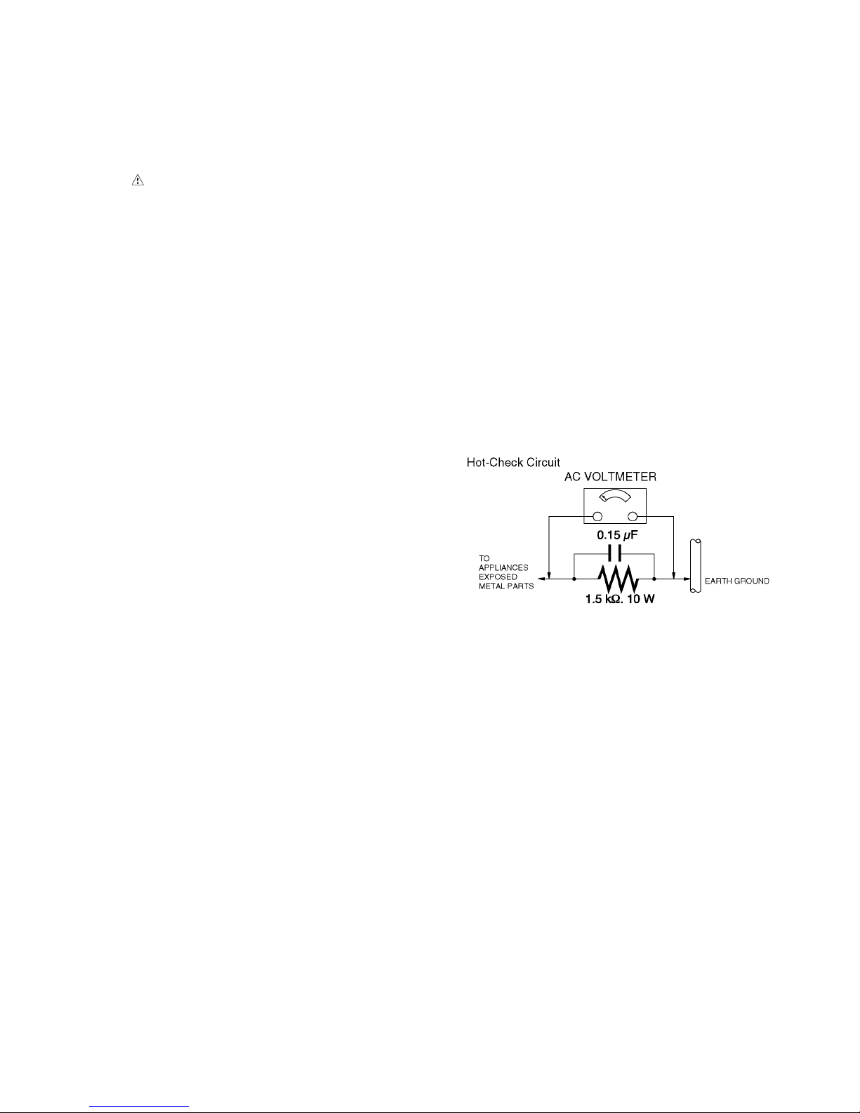
1.3. Leakage Current Hot Check
(See Figure 1.)
1. Plug the AC cord directly into the AC outlet. Do not use
an isolation transformer for this check.
2. Connect a 1.5 kΩ, 10 W resistor, in parallel with a 0.15 μF
capacitor, between each exposed metallic part on the set
and a good earth ground, as shown in Figure 1.
3. Use an AC voltmeter, with 1 kΩ/V or more sensitivity, to
measure the potential across the resistor.
4. Check each exposed metallic part, and measure the voltage at each point.
5. Reverse the AC plug in the AC outlet and repeat each of
the above measurements.
6. The potential at any point should not exceed 0.75 V RMS.
A leakage current tester (Simpson Model 229 or equivalent) may be used to make the hot checks, leakage current must not exceed 1/2 mA. In case a measurement is
outside of the limits specified, there is a possibility of a
shock hazard, and the equipment should be repaired and
rechecked before it is returned to the customer.
Figure. 1

4
2Warning
2.1. Prevention of Electrostatic Discharge (ESD) to Electrostatically
Sensitive (ES) Devices
Some semiconductor (solid state) devices can be damaged easily by static electricity. Such components commonly are called Electrostatically Sensitive (ES) Devices. Examples of typical ES devices are integrated circuits and some field-effect transistors and
semiconductor "chip" components. The following techniques should be used to help reduce the incidence of component damage
caused by electrostatic discharge (ESD).
1. Immediately before handling any semiconductor component or semiconductor-equipped assembly, drain off any ESD on your
body by touching a known earth ground. Alternatively, obtain and wear a commercially available discharging ESD wrist strap,
which should be removed for potential shock reasons prior to applying power to the unit under test.
2. After removing an electrical assembly equipped with ES devices, place the assembly on a conductive surface such as aluminum foil, to prevent electrostatic charge buildup or exposure of the assembly.
3. Use only a grounded-tip soldering iron to solder or unsolder ES devices.
4. Use only an antistatic solder removal device. Some solder removal devices not classified as "antistatic (ESD protected)" can
generate electrical charge sufficient to damage ES devices.
5. Do not use freon-propelled chemicals. These can generate electrical charges sufficient to damage ES devices.
6. Do not remove a replacement ES device from its protective package until immediately before you are ready to install it. (Most
replacement ES devices are packaged with leads electrically shorted together by conductive foam, aluminum foil or comparable conductive material).
7. Immediately before removing the protective material from the leads of a replacement ES device, touch the protective material
to the chassis or circuit assembly into which the device will be installed.
CAUTION :
Be sure no power is applied to the chassis or circuit, and observe all other safety precautions.
8. Minimize bodily motions when handling unpackaged replacement ES devices. (Otherwise harmless motion such as the
brushing together of your clothes fabric or the lifting of your foot from a carpeted floor can generate static electricity (ESD) sufficient to damage an ES device).
2.2. How to Recycle the Lithium Ion Battery (U.S. Only)
5
2.3. Caution for AC Cord
(For E/GC)
2.3.1. Information for Your Safety
IMPORTANT
Your attention is drawn to the fact that recording of prerecorded tapes or discs or other published or broadcast
material may infringe copyright laws.
WARNING
To reduce the risk of fire or shock hazard, do not expose
this equipment to rain or moisture.
CAUTION
To reduce the risk of fire or shock hazard and annoying
interference, use the recommended accessories only.
FOR YOUR SAFETY
DO NOT REMOVE THE OUTER COVER
To prevent electric shock, do not remove the cover. No user
serviceable parts inside. Refer servicing to qualified service
personnel.
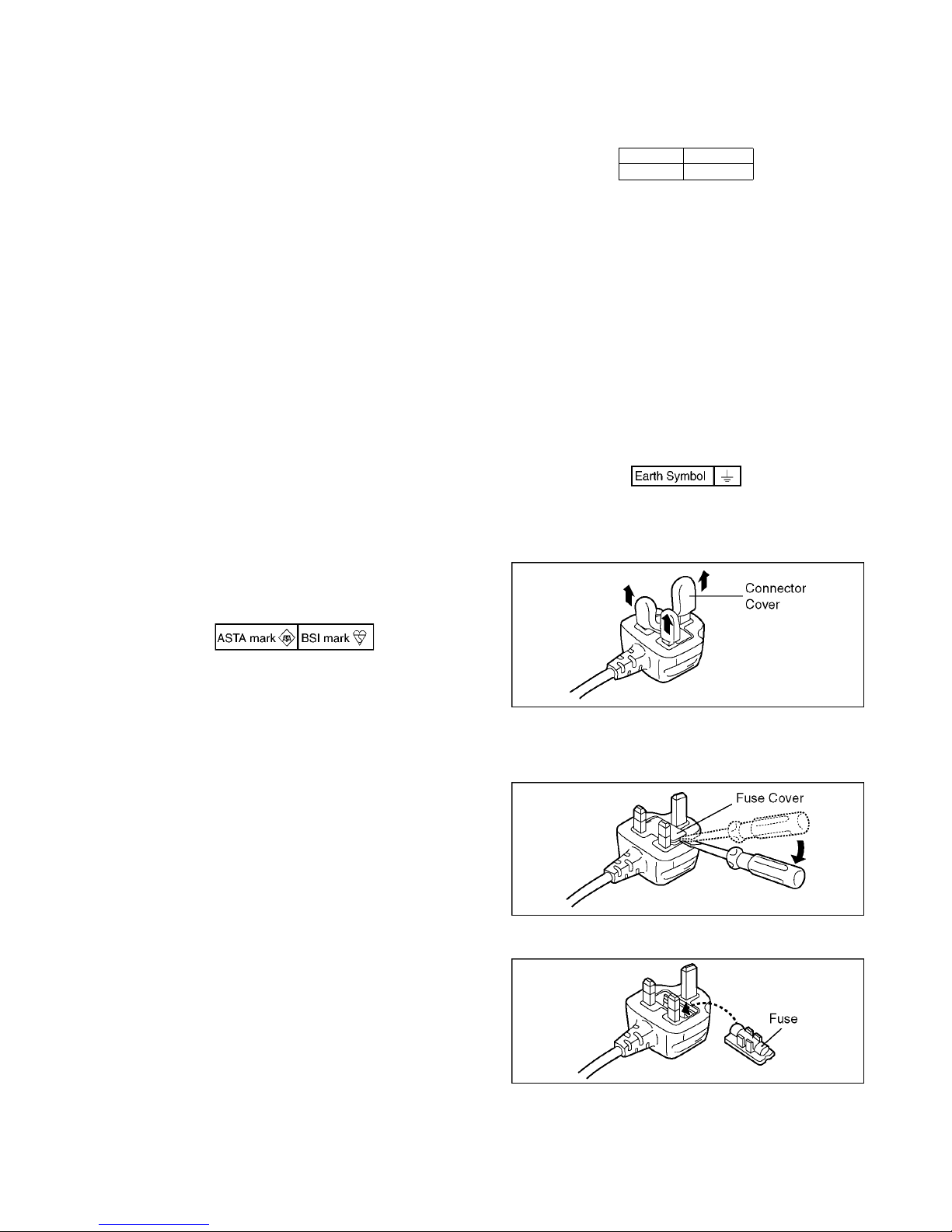
2.3.2. Caution for AC Mains Lead
For your safety, please read the following text carefully.
This appliance is supplied with a moulded three-pin mains plug
for your safety and convenience.
A 5-ampere fuse is fitted in this plug.
Should the fuse need to be replaced please ensure that the
replacement fuse has a rating of 5 amperes and it is approved
by ASTA or BSI to BS1362
Check for the ASTA mark or the BSI mark on the body of the
fuse.
If the plug contains a removable fuse cover you must ensure
that it is refitted when the fuse is replaced.
If you lose the fuse cover, the plug must not be used until a
replacement cover is obtained.
A replacement fuse cover can be purchased from your local
Panasonic Dealer.
If the fitted moulded plug is unsuitable for the socket outlet in
your home then the fuse should be removed and the plug cut
off and disposed of safety.
There is a danger of severe electrical shock if the cut off plug is
inserted into any 13-ampere socket.
If a new plug is to be fitted please observe the wiring code as
shown below.
If in any doubt, please consult a qualified electrician.
2.3.2.1. Important
The wires in this mains lead are coloured in accordance with
the following code:
As the colours of the wires in the mains lead of this appliance
may not correspond with the coloured markings identifying the
terminals in your plug, proceed as follows:
The wire which is coloured BLUE must be connected to the terminal in the plug which is marked with the letter N or coloured
BLACK.
The wire which is coloured BROWN must be connected to the
terminal in the plug which is marked with the letter L or coloured
RED.
Under no circumstances should either of these wires be connected to the earth terminal of the three pin plug, marked with
the letter E or the Earth Symbol.
2.3.2.2. Before Use
Remove the Connector Cover as follows.
2.3.2.3. How to Replace the Fuse
1. Remove the Fuse Cover with a screwdriver.
2. Replace the fuse and attach the Fuse cover.
Blue Neutral
Brown Live
6
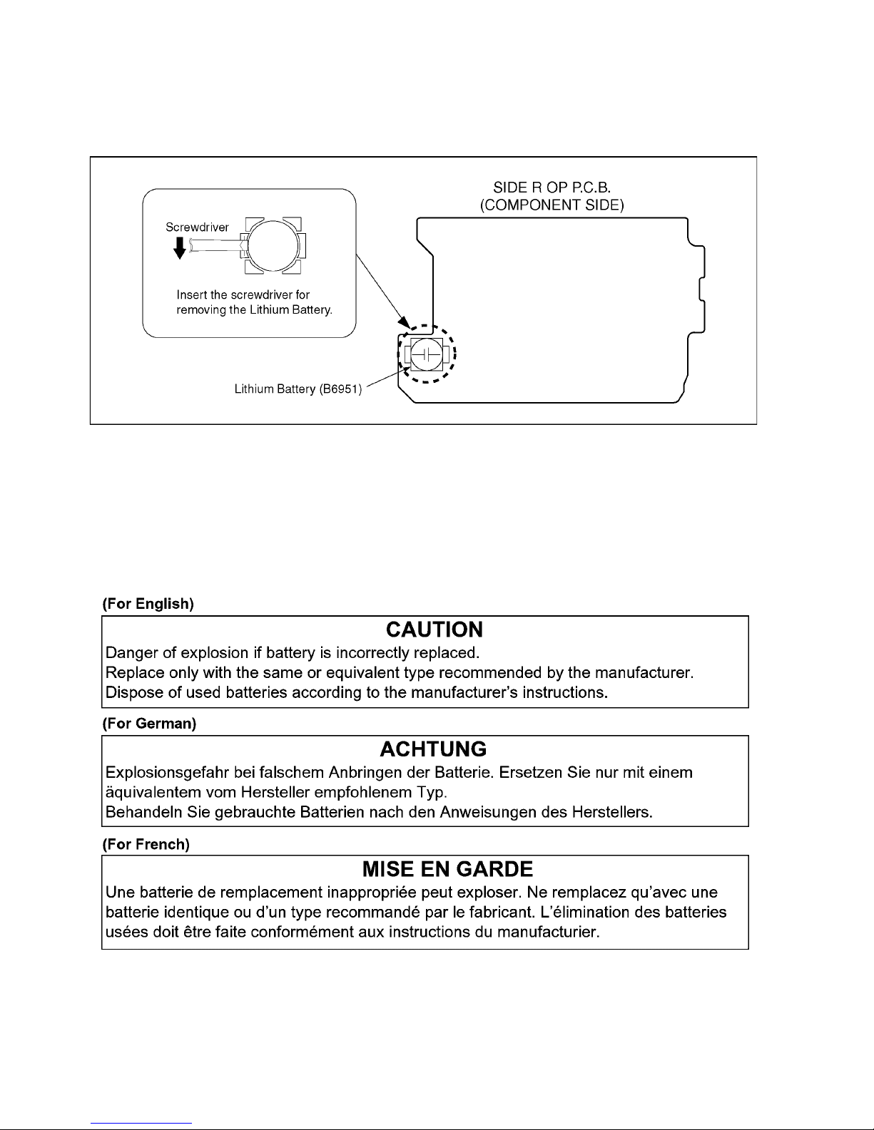
2.4. How to Replace the Lithium Battery
2.4.1. Replacement Procedure
1. Remove the SIDE_R_OP P.C.B.. (Refer to Disassembly Procedures.)
2. Remove the Lithium battery (Ref. No. “B6951” at component side of SIDE_R_OP P.C.B.) and then replace it into new one.
NOTE:
This Lithium battery is a critical component.
(Type No.: ML-614S/ZTK Manufactured by Energy Company, Panasonic Corporation)
It must never be subjected to excessive heat or discharge.
It must therefore only be fitted in requirement designed specifically for its use.
Replacement batteries must be of same type and manufacture.
They must be fitted in the same manner and location as the original battery, with the correct polarity contacts observed.
Do not attempt to re-charge the old battery or re-use it for any other purpose.
It should be disposed of in waste products destined for burial rather than incineration.
7
3 Service Navigation
3.1. Introduction
This service manual contains technical information, which allow service personnel’s to understand and service this model.
Please place orders using the parts list and not the drawing reference numbers.
If the circuit is changed or modified, the information will be followed by service manual to be controlled with original service manual.
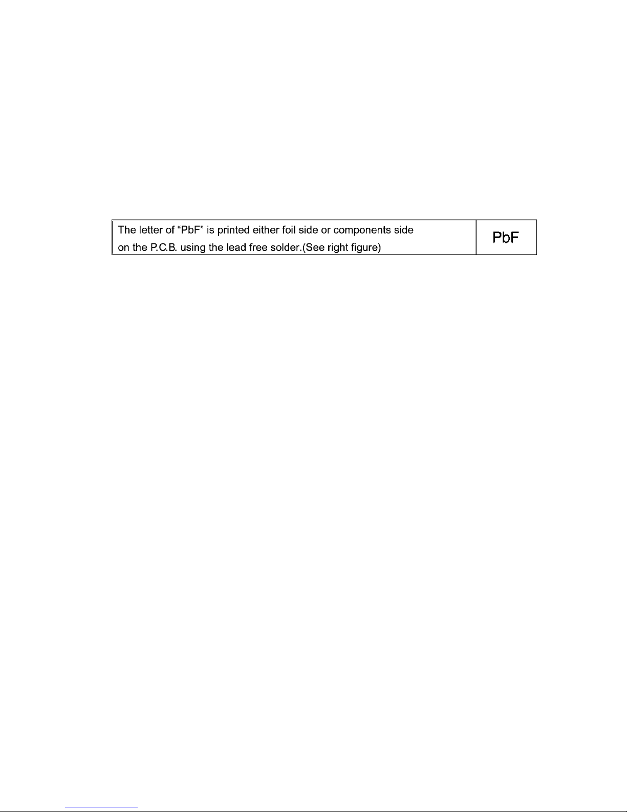
3.2. General Description About Lead Free Solder (PbF)
The lead free solder has been used in the mounting process of all electrical components on the printed circuit boards used for this
equipment in considering the globally environmental conservation.
The normal solder is the alloy of tin (Sn) and lead (Pb). On the other hand, the lead free solder is the alloy mainly consists of tin
(Sn), silver (Ag) and Copper (Cu), and the melting point of the lead free solder is higher approx.30°C (86°F) more than that of the
normal solder.
Distinction of P.C.B. Lead Free Solder being used
Service caution for repair work using Lead Free Solder (PbF)
• The lead free solder has to be used when repairing the equipment for which the lead free solder is used.
(Definition: The letter of “PbF” is printed on the P.C.B. using the lead free solder.)
• To put lead free solder, it should be well molten and mixed with the original lead free solder.
• Remove the remaining lead free solder on the P.C.B. cleanly for soldering of the new IC.
• Since the melting point of the lead free solder is higher than that of the normal lead solder, it takes the longer time to melt the
lead free solder.
• Use the soldering iron (more than 70W) equipped with the temperature control after setting the temperature at 350±30°C
(662±86°F).
Recommended Lead Free Solder (Service Parts Route.)
• The following 3 types of lead free solder are available through the service parts route.
RFKZ03D01KS-----------(0.3mm 100g Reel)
RFKZ06D01KS-----------(0.6mm 100g Reel)
RFKZ10D01KS-----------(1.0mm 100g Reel)
Note
* Ingredient: tin (Sn) 96.5%, silver (Ag) 3.0%, Copper (Cu) 0.5%, Cobalt (Co) / Germanium (Ge) 0.1 to 0.3%
3.3. Important Notice 1:(Other than U.S.A. and Canadian Market)
1. The service manual does not contain the following information, because of the impossibility of servicing at component level
without concerned equipment/facilities.
a. Schematic diagram, Block Diagram and P.C.B. layout of MAIN P.C.B..
b. Parts list for individual parts for MAIN P.C.B..
When a part replacement is required for repairing MAIN P.C.B., replace as an assembled parts. (Main P.C.B.)
2. The following category is /are recycle module part. Please send it/them to Central Repair Center.
• MAIN P.C.B. (VEP03J34A: HDC-Z10000E/GC/GK/P)
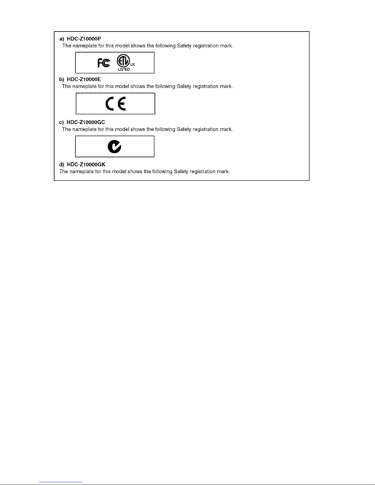
3.4. How to Define the Model Suffix
(NTSC or PAL model)
There are seven kinds of HDC-Z10000.
• a) HDC-Z10000P
• b) HDC-Z10000E
• c) HDC-Z10000GC
• d) HDC-Z10000GK
What is the difference is that the “INITIAL SETTING” data which is stored in Flash ROM mounted on Main P.C.B..
3.4.1. Defining methods:
To define the model suffix to be serviced, refer to the rating label and caution label which are putted on the Unit.
8
NOTE:
After replacing the MAIN P.C.B., be sure to achieve adjustment.
The adjustment instruction is available at “software download” on the “Support Information from NWBG/VDBG-AVC” web-site in
“TSN system”, together with Maintenance software.
9
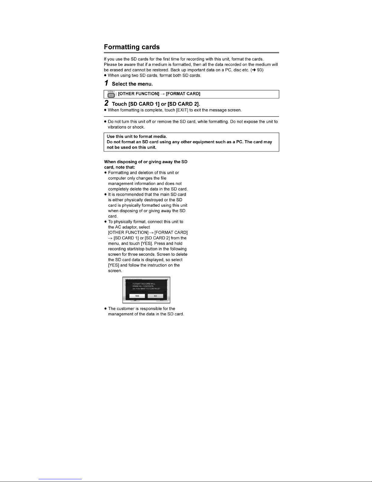
3.5. Formatting
10
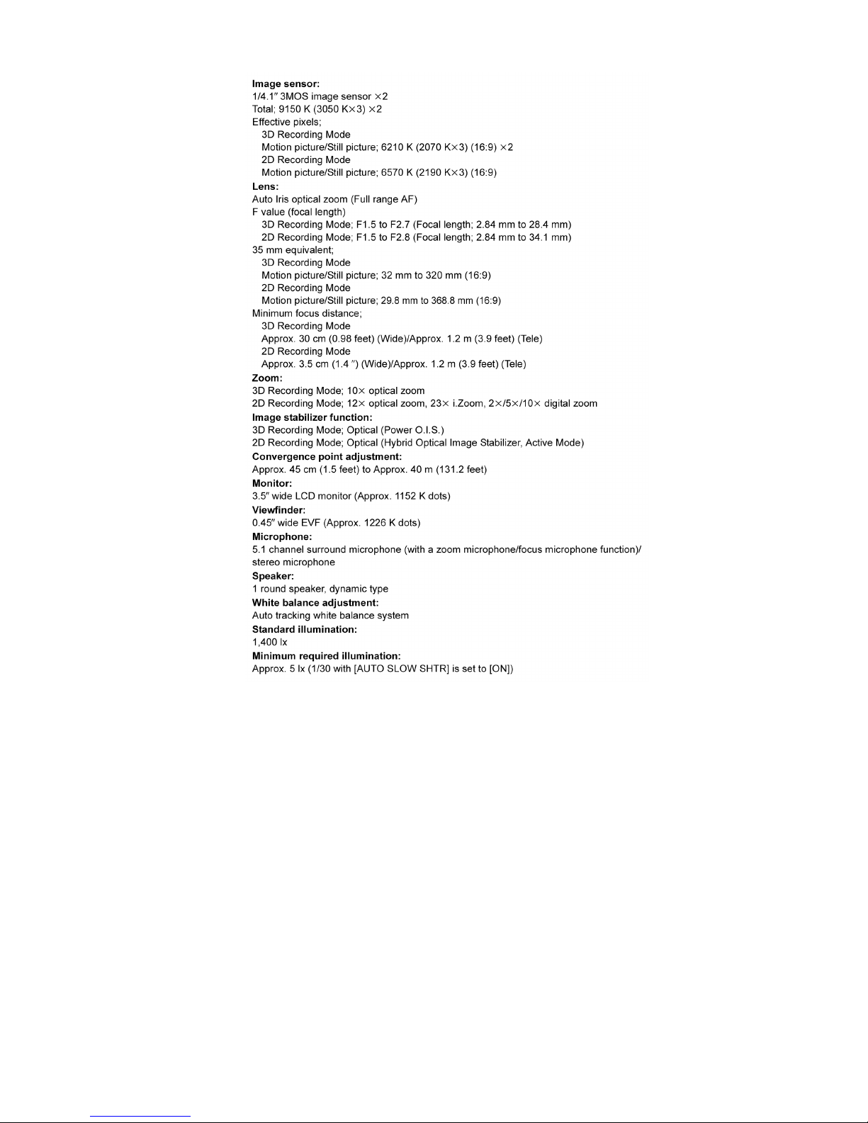
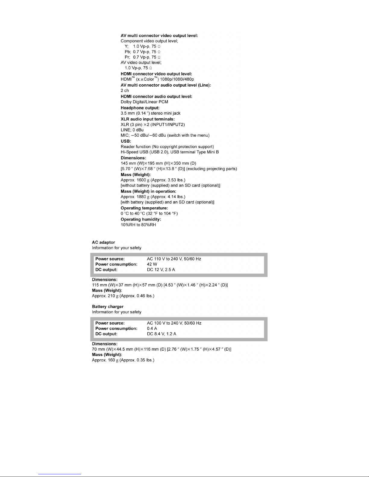
4 Specifications
11
12
13
14
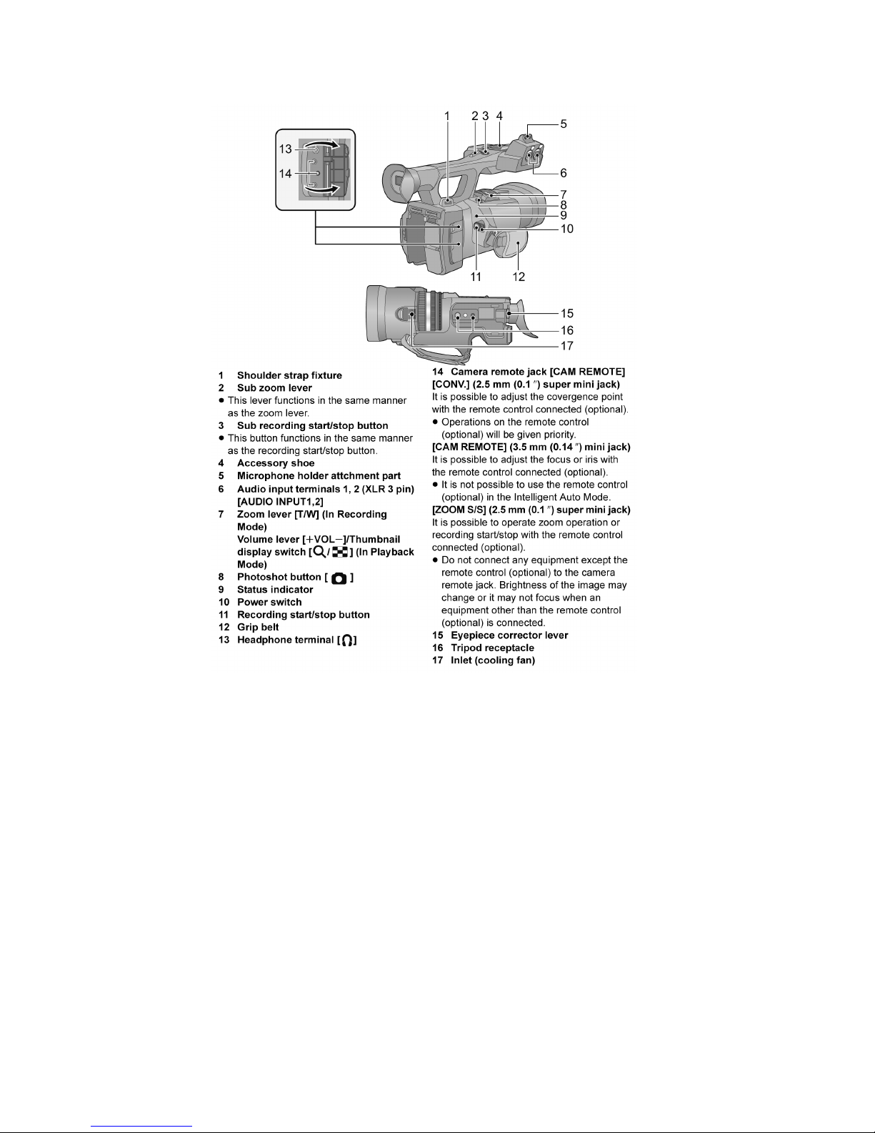
5 Location of Controls and Components
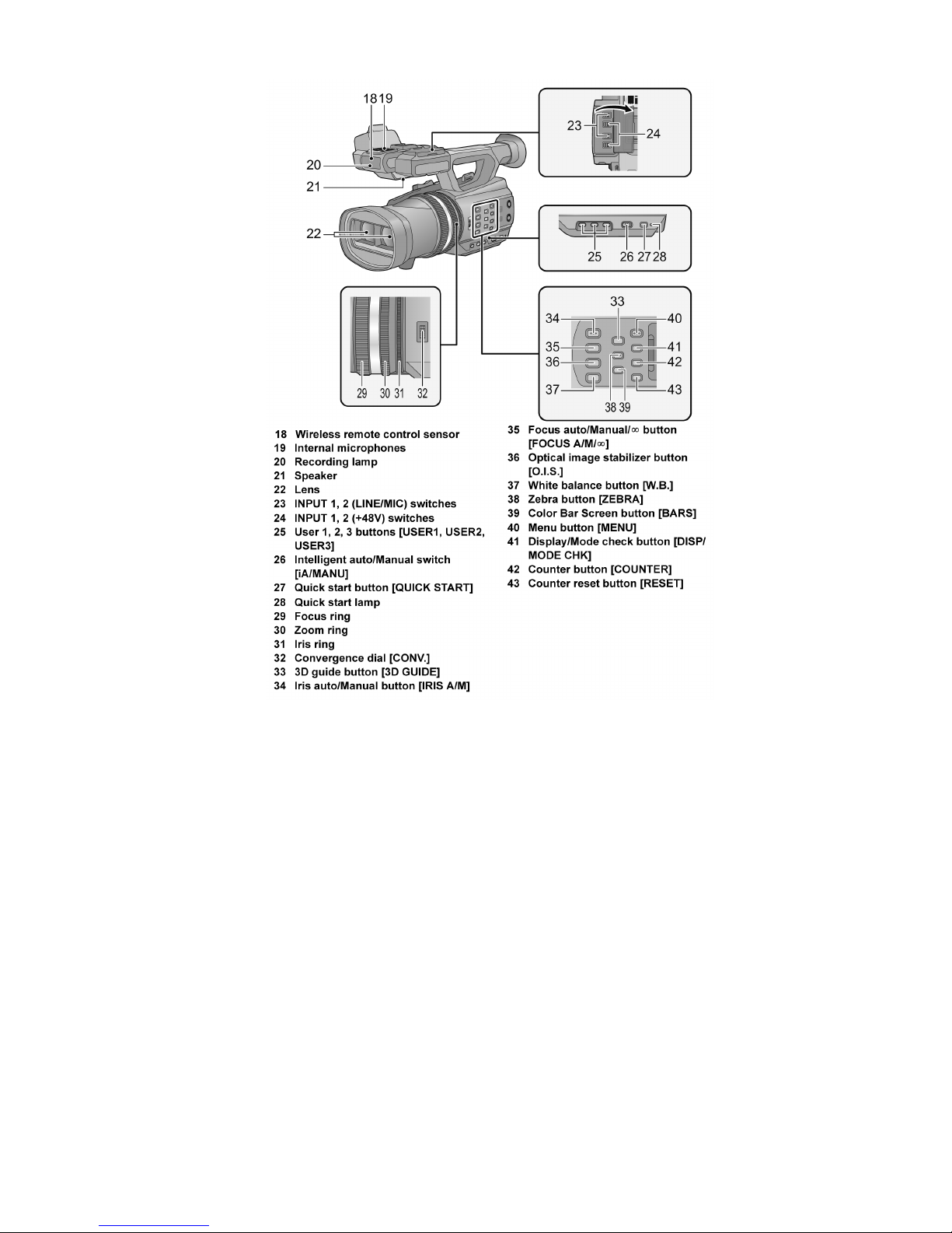
15
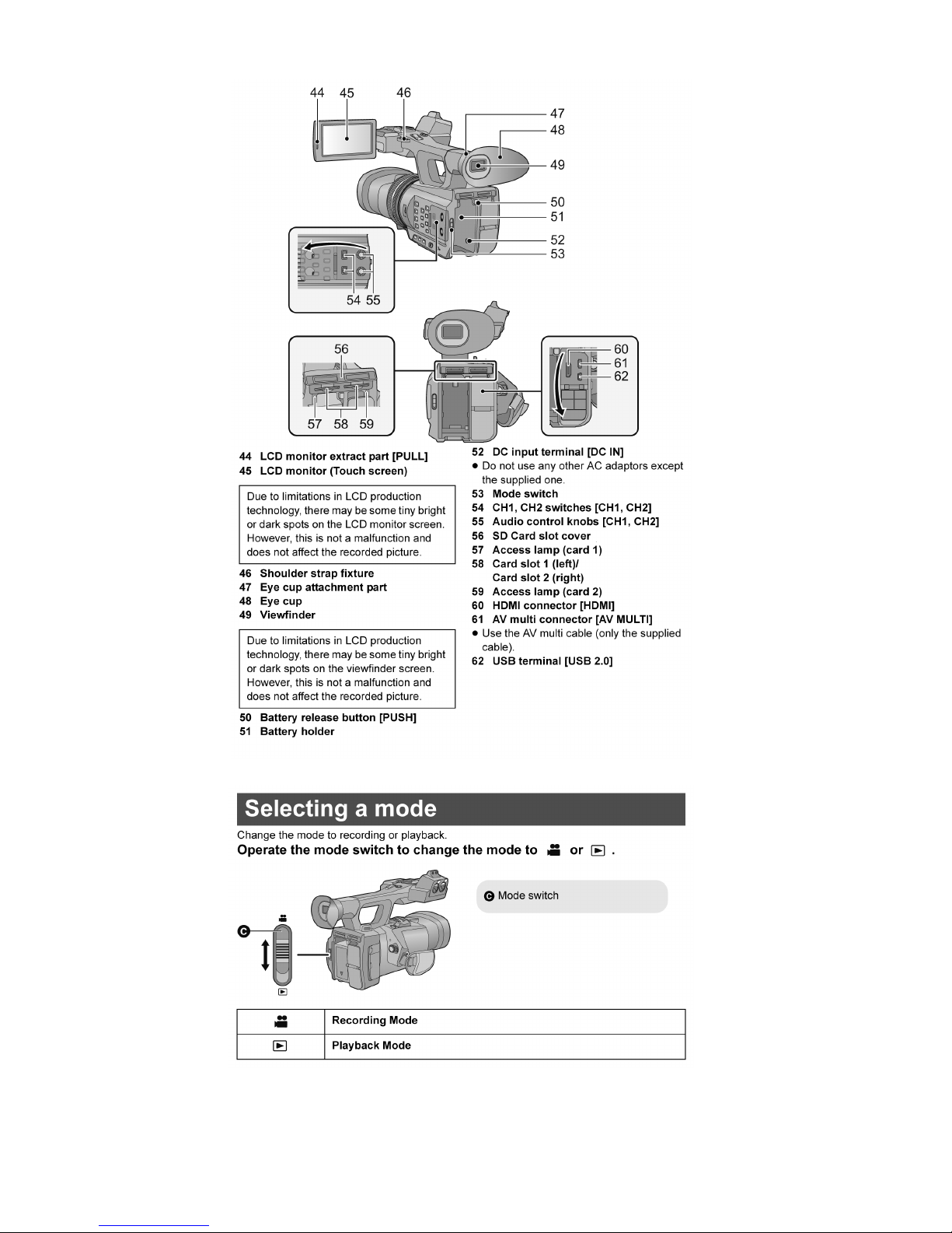
16
17
18
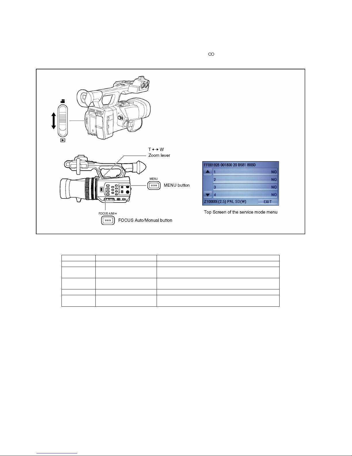
6 Service Mode
1. Indication method of the service menu
Set the mode switch "Recording" mode.
2. Keep pressing the "MENU" button, "Zoom lever" to W side and "FOCUS A/M/ " button for more than 3 seconds until the top
screen of the Service Mode Menu being displayed.
Service mode menu
NOTE:
Do not using service mode except above table of Service mode menu.
3. End method of the top screen of the service mode menu
Touch the [ EXIT ] of LCD to end the service mode, and then POWER OFF.
Screen display Contents Function
1 Factory settings Function to throw a product up in a factory shipment state
4 Lock search history indication Display the camera system error cord for three histories saved
in EEPROM
5 Power ON self check result dis-
play
Power ON self check (function to diagnose correct function of
the device and interface between devices) result display
10 Erasing the lock histories Erasing the error histories (working time is not erased)
12 Camera data indications while
the video playback
Display the camera informations (Shutter speed, Iris value,
White balance and focal length) while playing recorded video

19
6.1. Lock Search History Indication
Touch the [ 4 ] of LCD, select Lock search history indication.
Operation specifications
Indication contents
• Lock search history indication
Display the camera system error cord for three histories saved in EEPROM.
• The error cord contents which are displayed
Cutting of battery connection or AC power supply connection to end the service mode.
Error code Function
51 Focus control ( L ) is abnormal
52 Zoom control ( L ) is abnormal
53 OIS lens control ( L ) is abnormal
D1 Focus control ( R ) is abnormal
D2 Zoom control ( R ) is abnormal
D3 OIS lens control ( R ) is abnormal
33 IC3401 internal communication is abnormal.
20
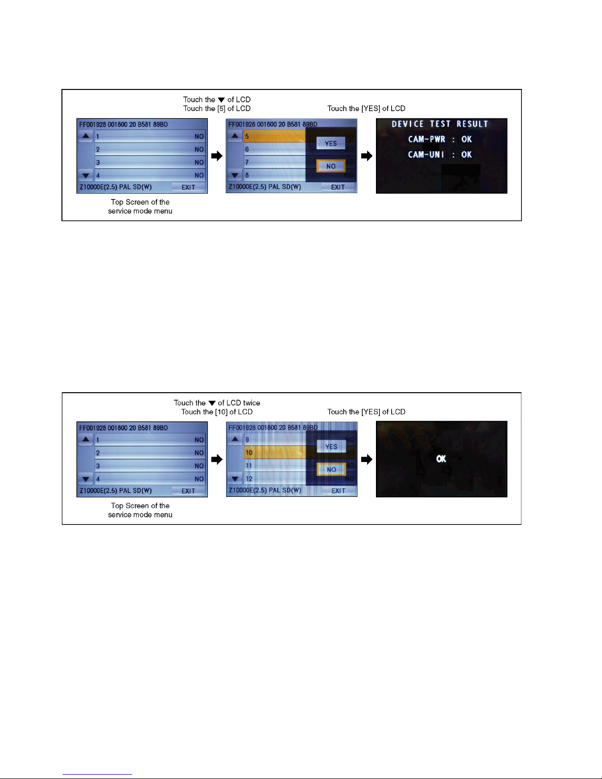
6.2. Power ON Self Check Result Display
Touch the [ 5 ] of LCD, select Power ON self check result display.
Operation specifications
Indication contents
• Power ON self check result display
Function to diagnose correct function of the device and interface between devices result display.
Display the following communication test result.
-CAM-PWR : Communication test between IC3401 to IC2304
-CAM-UNI : IC3401 internal communication test.
Display other than "OK" are abnormalities of each lines.
Cutting of battery connection or AC power supply connection to end the service mode.
6.3. Erasing the lock histories
Touch the [ 10 ] of LCD, select erasing the lock histories execution.
Operation specifications
Indication contents
• Erasing the error histories stored in EEPROM. (working time is not erased)
Press the power button and turn off.
21
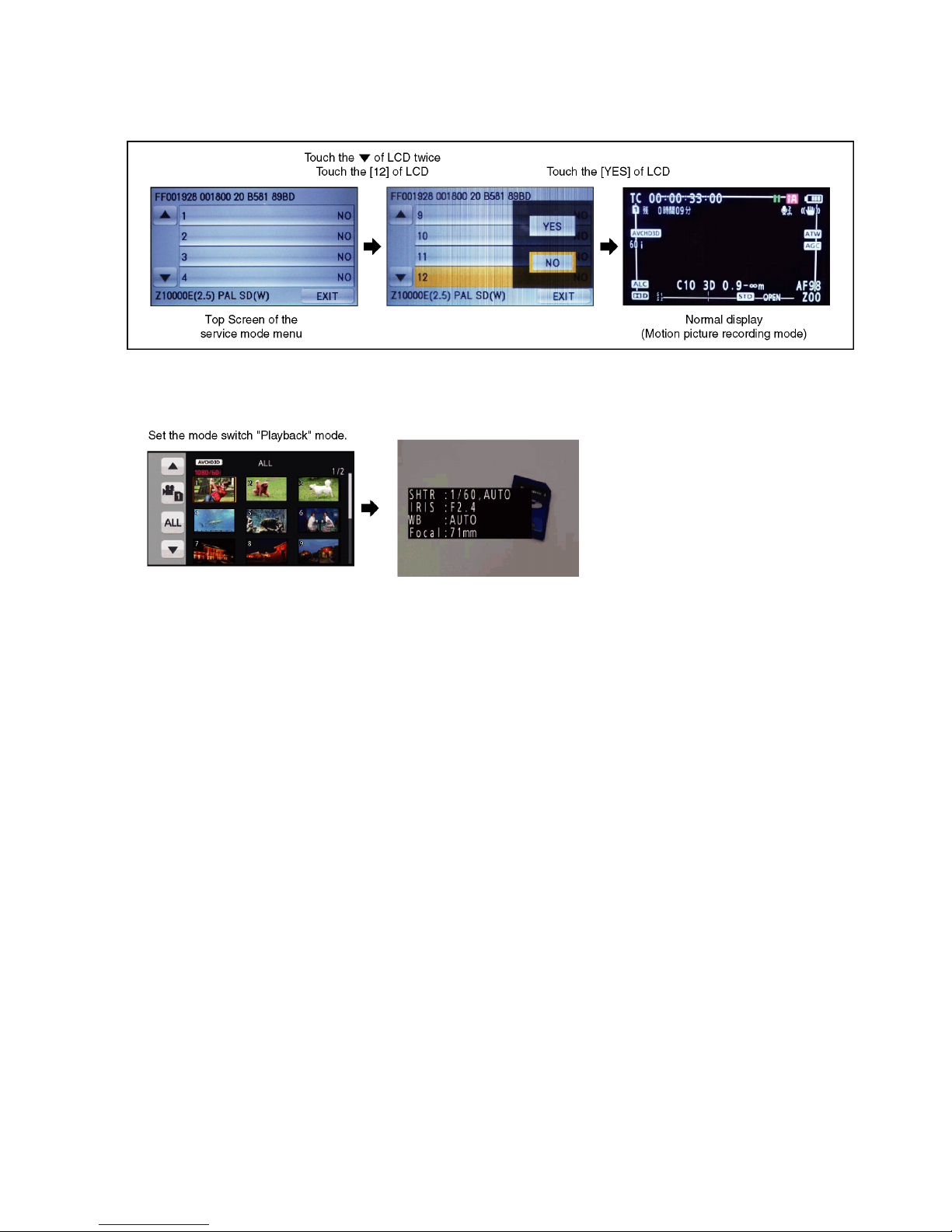
6.4. Camera data indications while the video playback
Touch the [ 12 ] of LCD, select indicating the camera informations while playing back the recorded video.
Operation specifications
Indication contents
• While playing back the recorded videos, the camera informations (Shutter speed, Iris value, White balance and focal length) are
superimposed on the LCD screen.
Press the power button and turn off.
22
7 Troubleshooting Guide
Failure diagnosis of a lens unit
When 3D Recording has abnormalities, please check the following and perform failure diagnosis of a lens unit.
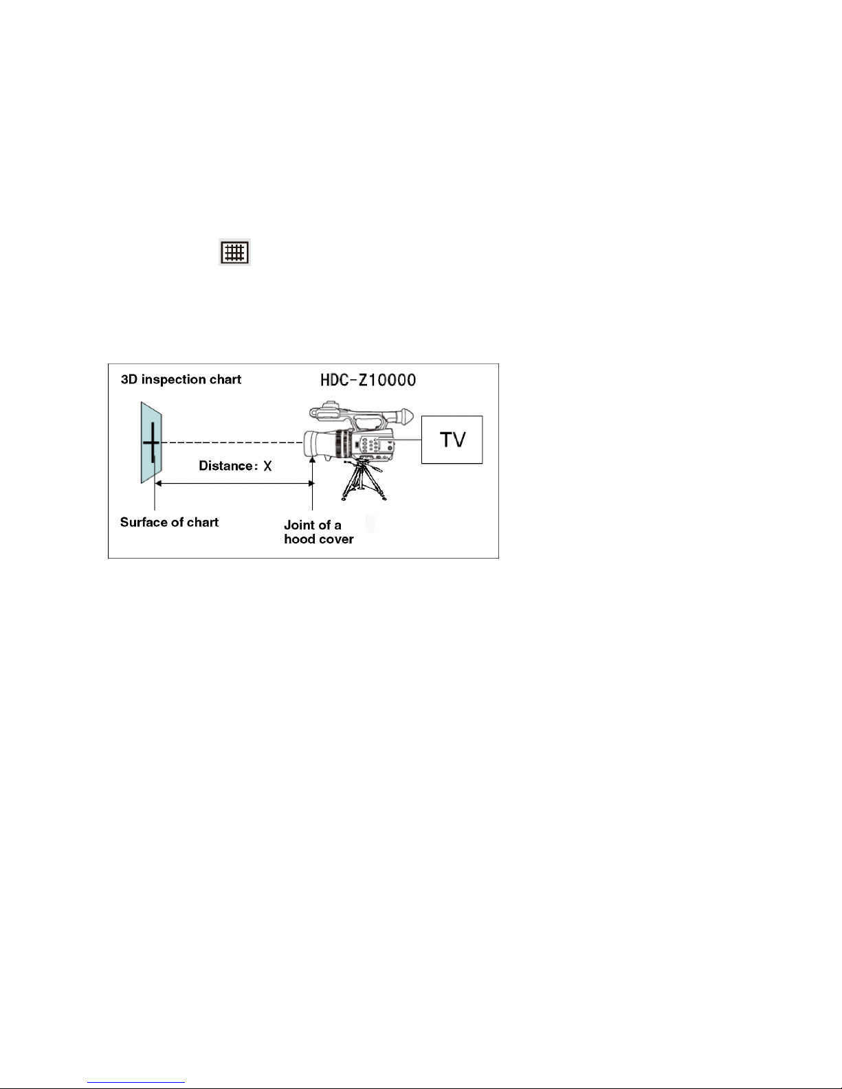
7.1. Preparation
1. Set up HDC-Z10000 as follows.
• 3D Recording Mode
• 3D display is set to MIX display
• Convergence reset
• Display a guideline.
2. Set up connection as follows.
• Stick 3D inspection chart of attachment in adjustment software on the perpendicular surface of a wall etc.
• Install HDC-Z10000 in the front of 3D inspection chart.
• It fixes so that the horizontal line of 3D inspection chart and guideline may be displayed horizontally on LCD screen.
Figure of connection
* 3D inspection chart is attached to adjustment software.
23
7.2. Check
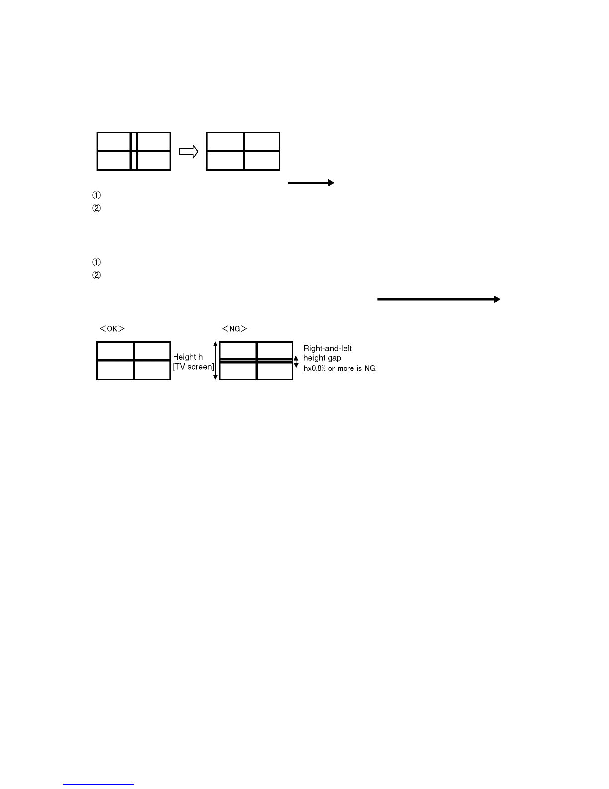
7.2.1. The check of a Convergence Gap
1. Check by 2DTV (HDMI Connection).
2. Record a chart in a zoom W side and a macro mode (MACR set up with the USER button).
3. Check each distance X when the distance between a chart and a main unit is changed and the vertical bar of a right-and-left
picture is coincided on TV screen (or LCD screen).
4. When distance X is different from the following spec. The lens unit exchange.
zoom W side : X=1.4m±30cm
macro mode (zoom W side) : X=45cm±3cm
7.2.2. The check of a Right-and-Left Height Gap
1. Check by 2DTV (HDMI Connection).
2. Measure in each distance in a zoom T side(×10) and a macro mode (zoom W side).
zoom T side : X=1.4m±30cm
macro mode (zoom W side) : X=45cm±3cm
3. Check the amount of height gaps of the horizontal line of a right-and-left picture on TV screen.
When TV screen height has 0.8% or more of the amount of height gaps The lens unit
exchange.
24
8 Disassembly and Assembly Instructions
8.1. Disassembly Flow Chart for the Unit
This is a disassembling chart.
When assembling, perform this chart conversely.
25
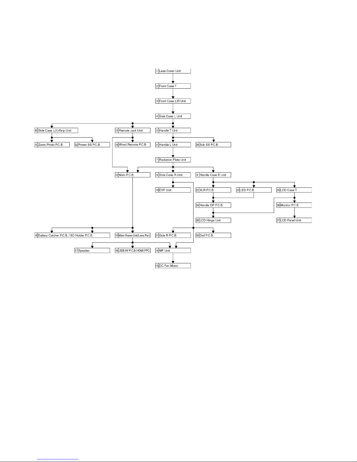
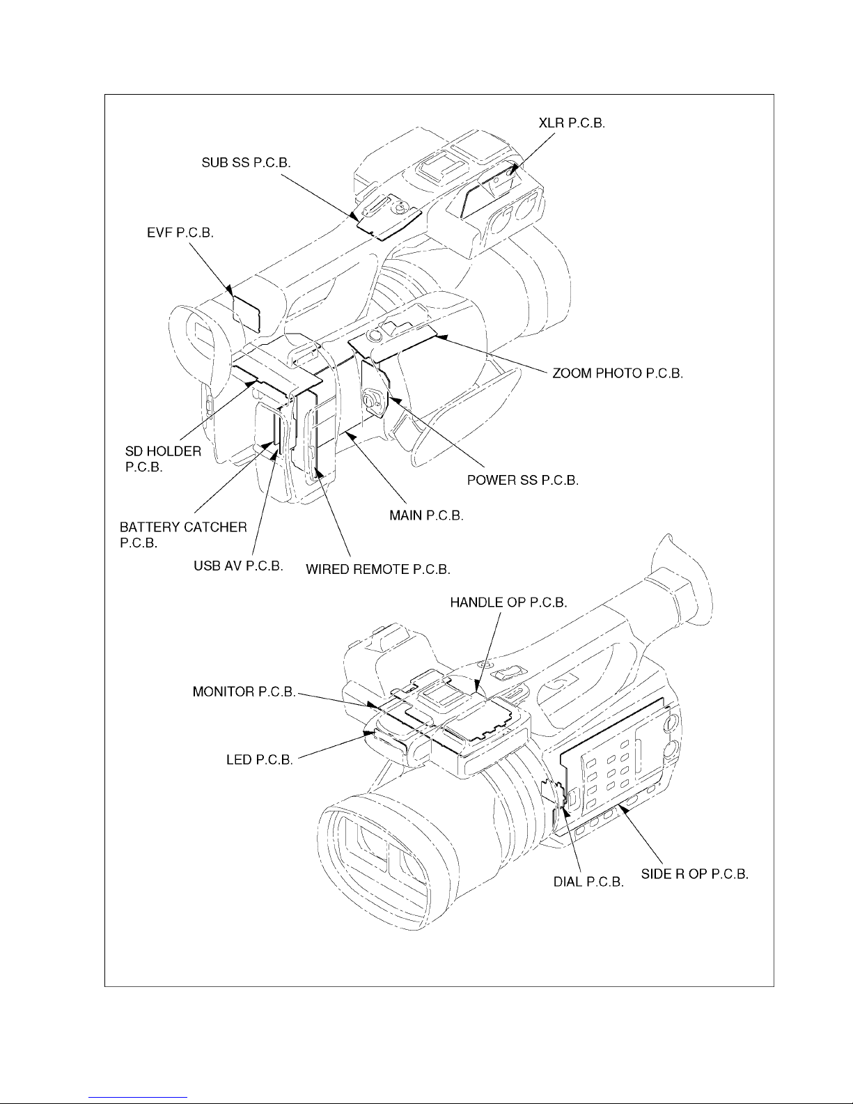
8.2. P.C.B. Location
26
8.3. Disassembly Procedure for the Unit
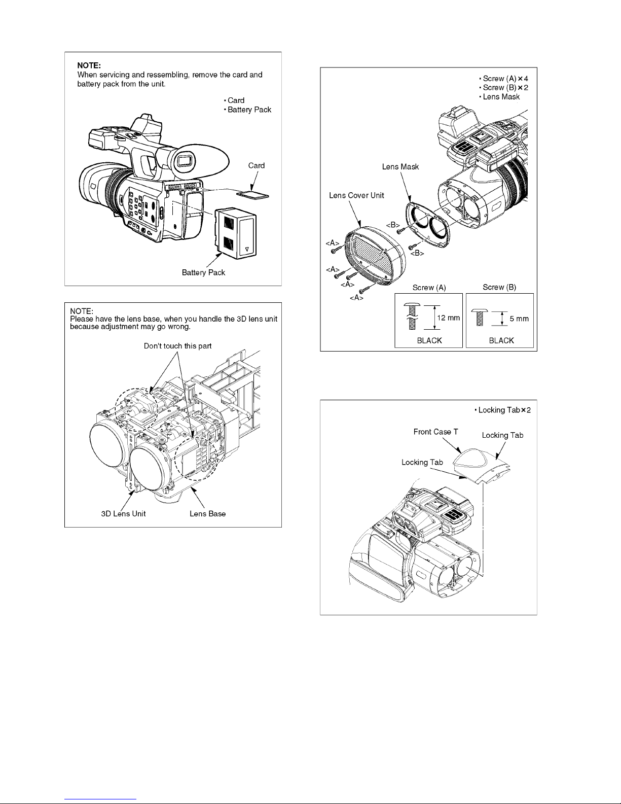
No. Item Fig. Removal
1 Lens Cover Unit (Fig. D1) 4 Screws (A)
2 Screws (B)
Lens Cover Unit
Lens Mask
2 Front Case T (Fig. D2) 2 Locking Tabs
Front Case T
3 Front Case L/R
Unit
(Fig. D3) 3 Screws (C)
(Fig. D4) 1 Screw (D)
3 Locking Tabs
Front Case L Unit
Front Case R Unit
4 Side Case L Unit (Fig. D5) 1 Screw (E)
7 Screws (F)
1 Screw (G)
FP6020 (Flex)
FP6021 (Flex)
Side Case L Unit
5 Handle T Unit (Fig. D6) 4 Screws (H)
4 Screws (I)
2 Screws (J)
FP6716 (Flex)
Handle T Unit
6 Handle Case L
Unit
(Fig. D7) 2 Screws (K)
1 Screw (L)
1 Screw (M)
2 Locking Tabs
Handle Case L Unit
7 Radiation Plate
Unit
(Fig. D8) 2 Screws (N)
1 Locking Tab
FP6009 (Flex)
Radiation Plate Unit
8 Handle Case B
Unit
(Fig. D9) 2 Screws (O)
FP6008 (Flex)
FP6012 (Flex)
P6710 (Connector)
PS6003 (Flex)
Handle Case B Unit
9 Side Case R Unit (Fig. D10) 3 Screws (P)
2 Screws (Q)
1 Screw (R)
3 Locking Tabs
Side Case R Unit
10 EVF Unit (Fig. D11) 1 Screw (S)
4 Locking Tabs
PS6004 (Connector)
EVF Wire Guide
EVF Unit
11 Remote Jack Unit (Fig. D12) 2 Screws (T)
FP6022 (Flex)
P6502 (Connector)
Wire
Remote Jack Unit
12 Main P.C.B. (Fig. D13) 4 Screws (U)
SD FPC
FP6002 (Flex)
FP6003 (Flex)
FP6005 (Flex)
FP6006 (Flex)
FP6011 (Flex)
P6001 (Connector)
P6024 (Connector)
PS6002 (Connector)
PS6011 (Connector)
Main P.C.B.
13 Main Frame Unit /
Lens Part
(Fig. D14) 4 Screws (V)
Main Frame Unit
Lens Part
14 MF Unit (Fig. D15) 4 Screws (W)
4 Ribs
15 DC Fan Motor (Fig. D16) 1 Screw (X)
3 Locking Tabs
Fan Cover
(Fig. D17) DC Fan Motor
16 USB AV P.C.B. /
HDMI FPC
(Fig. D18) 1 Screw (Y)
Rear Jack Unit
(Fig. D19) 4 Screws (Z)
FP6471 (Flex)
USB AV FPC
Rear Jack Frame
USB AV P.C.B.
HDMI FPC
17 Speaker (Fig. D20) 2 Screws (a)
Speaker Angle
Speaker
18 Battery Catcher
P.C.B. / SD Holder
P. C .B .
(Fig. D21) 7 Screws (b)
1 Locking Tab
1 Rib
(Fig. D22) 2 Locking Tabs
FP6301 (Flex)
P6301 (Connector)
Battery Catcher FFC
Battery Catcher P.C.B.
(Fig. D23) 2 Screws (c)
SD Holder P.C.B.
19 Wired Remote
P. C .B .
(Fig. D24) 2 Screws (d)
1 Nut
FP6501 (Flex)
Wired Remote FFC
Remote Jack Frame
Wired Remote P.C.B.
20 Dial P.C.B. (Fig. D25) 2 Screws (e)
FP6951 (Flex)
Dial P.C.B.
21 Side R OP P.C.B.
Unit
(Fig. D26) 11 Screws (f)
FP6951 (Flex)
Side R OP FFC
Side R OP P.C.B.
Side Case R (1) Unit
22 XLR P.C.B. (Fig. D27) 4 Screws (g)
1 Screw (h)
FP4401 (Flex)
FP6712 (Flex)
XLR FFC
XLR P.C.B.
23 LED P.C.B. (Fig. D28) FP6401 (Flex)
FP6710 (Flex)
FP6711 (Flex)
MIC Unit
LED P.C.B.
(Fig. D29) Tally Panel Light
Sensor Window
No. Item Fig. Removal
27
24 Handle OP P.C.B. (Fig. D30) 2 Screws (i)
1 Screw (j)
FP6714 (Flex)
(Fig. D31) FP6717 (Flex)
FP6718 (Flex)
PS6719 (Connector)
SW Knob Sheet
XLR SW Knob A
XLR SW Knob B
Handle OP A FFC
Handle OP B FFC
Handle Slim Wire Unit
Handle OP P.C.B.
25 LCD Case T (Fig. D32) 1 Screw (k)
(Fig. D33) 2 Screws (l)
1 Screw (m)
(Fig. D34) 6 Locking Tabs
FP901 (Flex)
FP902 (Flex)
LCD Case T
26 Monitor P.C.B. (Fig. D35) 3 Locking Tabs
FP903 (Flex)
FP904 (Flex)
FP905 (Flex)
LCD Frame
(Fig. D36) Monitor P.C.B.
Reflection Sheet
Light Guide Plate
27 LCD Panel Unit (Fig. D37) Diffusion Sheet
Prism Sheet A
Prism Sheet B
(Fig. D38) LGP Holder
LCD Panel Unit
TP Spacer
Magnet
LCD Case B
28 LCD Hinge Unit (Fig. D39) 2 Screws (n)
LCD Hinge Unit
(Fig. D40) 2 Screws (o)
Hinge Cover B
(Fig. D41) Ball Spring
Ball Spacer
Stainless Ball
Magnet
Hinge Cover T
(Fig. D42) Monitor FPC
(Fig. D43) FPC Hold Piece
Shaft Unit
(Fig. D44) Monitor FPC
29 Sub SS Zoom
P. C .B .
(Fig. D45) 4 Screws (p)
1 Screw (q)
Shoe Spring
Shoe Hold Plate
(Fig. D46) 4 Screws (r)
REC Button
Handle T (1) Unit
(Fig. D47) 1 Screw (s)
Shoulder Belt Angle F
(Fig. D48) 2 Screws (t)
FP6681 (Flex)
Sub SS Zoom FFC
Handle Mount Plate
Sub SS P.C.B.
30 Side Case L (1) /
Grip Unit
(Fig. D49) Grip Belt
(Fig. D50) 9 Screws (u)
Grip Unit
Side Case L (1) Unit
No. Item Fig. Removal
31 Zoom Photo P.C.B. (Fig. D51) 2 Screws (v)
Zoom Unit
(Fig. D52) FP6691 (Flex)
Zoom Photo FFC
(Fig. D53) 2 Screws (w)
Photo Shot Button
Photo Earth Plate
Zoom Base
(Fig. D54) 2 Screws (x)
Zoom Lever Cushion (B)
Zoom Photo P.C.B.
(Fig. D55) Zoom Lever
Zoom Lever Cushion (A)
Zoom SW (1) Unit
32 Power SS P.C.B. (Fig. D56) 3 Screws (y)
Belt Angle R
(Fig. D57) Power SS Unit
Grip Case AL Hoil
Grip Case
(Fig. D58) 1 Screw (z)
FP6601 (Flex)
Zoom Photo FFC
PW Panel Light
Power SS (1) Unit
Power SS P.C.B.
No. Item Fig. Removal
28
8.3.1. Removal of the Lens Cover Unit
(Fig. D1)
8.3.2. Removal of the Front Case T
(Fig. D2)
29
8.3.3. Removal of the Front Case L/R Unit
(Fig. D3)
(Fig. D4)
8.3.4. Removal of the Side Case L Unit
(Fig. D5)

30
8.3.5. Removal of the Handle T Unit
(Fig. D6)
8.3.6. Removal of the Handle Case L Unit
(Fig. D7)
 Loading...