

Panasonic HDC-SDT750PP, HDC-SDT750EG, HDC-SDT750EF, HDC-SDT750EE, HDC-SDT750EP Service Manual
...
© Panasonic Corporation 2010 Unauthorized copying and distribution is a violation of law.
ORDER NO. VM1009043CE
B27
High Definition Video Camera
Model No. HDC-SDT750PP
HDC-SDT750EB
HDC-SDT750EE
HDC-SDT750EF
HDC-SDT750EG
HDC-SDT750EP
HDC-SDT750GC
HDC-TMT750GC
HDC-TMT750GD
HDC-TMT750GK
HDC-TMT750GT
Vol. 1
Colour
(H)...........Gray Type
4

2
TABLE OF CONTENTS
PAGE PAGE
1 Safety Precautions -----------------------------------------------3
1.1. General Guidelines ----------------------------------------3
1.2. Leakage Current Cold Check ---------------------------3
1.3. Leakage Current Hot Check (See Figure 1.)--------3
1.4. How to Discharge the Capacitor on Flash
P.C.B.----------------------------------------------------------4
2Warning--------------------------------------------------------------5
2.1. Prevention of Electrostatic Discharge (ESD)
to Electrostatically Sensitive (ES) Devices ----------5
2.2. How to Recycle the Lithium Ion Battery (U.S.
Only)-----------------------------------------------------------5
2.3. Caution for AC Cord (For EB/GC) ---------------------6
2.4. How to Replace the Lithium Battery-------------------7
3 Service Navigation------------------------------------------------8
3.1. Introduction --------------------------------------------------8
3.2. General Description About Lead Free Solder
(PbF) ----------------------------------------------------------8
3.3. Important Notice 1:(Other than U.S.A. and
Canadian Market)------------------------------------------8
3.4. How to Define the Model Suffix (NTSC or PAL
model)---------------------------------------------------------9
3.5. Formatting--------------------------------------------------10
4 Specifications----------------------------------------------------11
5 Location of Controls and Components------------------14
6 Service Mode-----------------------------------------------------19
6.1. Built-in Memory Self Check Execution (HDCTMT750 only) ---------------------------------------------20
6.2. Lock Search History Indication -----------------------20
6.3. Power ON Self Check Result Display--------------- 21
7 Troubleshooting Guide----------------------------------------22
8 Service Fixture & Tools---------------------------------------23
8.1. When Replacing the Main P.C.B. --------------------23
8.2. Service Position ------------------------------------------23
9 Disassembly and Assembly Instructions--------------- 25
9.1. Disassembly Flow Chart for the Unit---------------- 25
9.2. PCB Location----------------------------------------------25
9.3. Disassembly Procedure for the Unit ----------------26
9.4. Disassembly Flow Chart for the 3D
Conversion Lens -----------------------------------------46
9.5. Disassembly Procedure of the 3D Coversion
Lens ---------------------------------------------------------46
10 Measurements and Adjustments --------------------------50
10.1. Electric Adjustment --------------------------------------50
11 Factory Setting---------------------------------------------------52
11.1. How To Turn On The Factory Settings?------------52
11 .2. What Is The Factory Settings? -----------------------53
3
1 Safety Precautions
1.1. General Guidelines
1. IMPORTANT SAFETY NOTICE
There are special components used in this equipment
which are important for safety. These part s are marked by
in the Schematic Diagrams, Circuit Board Layout,
Exploded Views and Replacement Parts List. It is essential that these critical parts should be replaced with manufacturer’s specified parts to prevent X-RADIATION,
shock, fire, or other hazards. Do not modify the original
design without permission of manufacturer.
2. An Isolation Transformer should always be used during
the servicing of AC Adaptor whose chassis is not isolated
from the AC power line. Use a transformer of adequate
power rating as this protects the technician from accidents resulting in personal injury from electrical shocks. It
will also protect AC Adaptor from being damaged by accidental shorting that may occur during servicing.
3. When servicing, observe the original lead dress. If a short
circuit is found, replace all parts which have been overheated or damaged by the short circuit.
4. After servicing, see to it that all the protective devices
such as insulation barriers, insulation papers shields are
properly installed.
5. After servicing, make the following leakage current
checks to prevent the customer from being exposed to
shock hazards.
1.2. Leakage Current Cold Check
1. Unplug the AC cord and connect a jumper between the
two prongs on the plug.
2. Measure the resistance value, with an ohmmeter,
between the jumpered AC plug and each exposed metallic cabinet part on the equipment such as screwheads,
connectors, control shafts, etc. When the exposed metallic part has a return path to the chassis, the reading
should be between 1 MΩ and 5.2 MΩ. When the exposed
metal does not have a return path to the chassis, the
reading must be infinity.
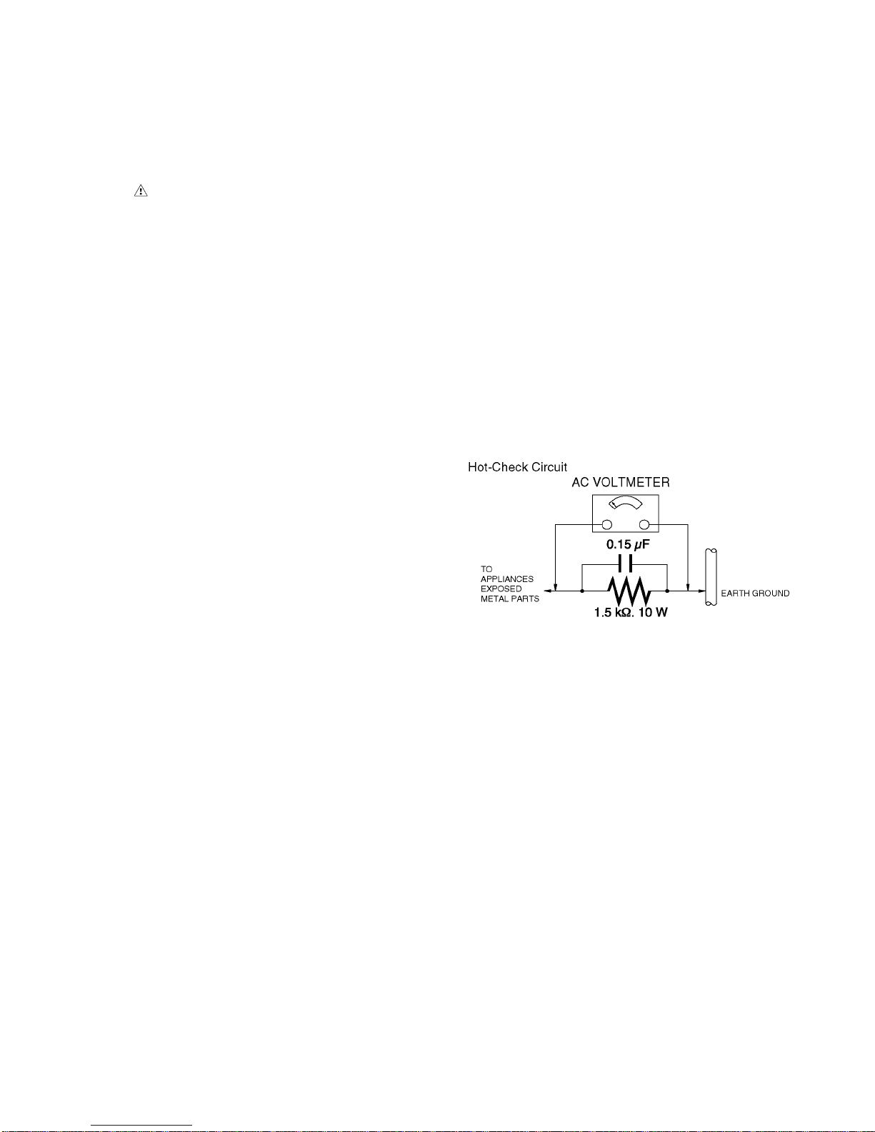
1.3. Leakage Current Hot Check
(See Figure 1.)
1. Plug the AC cord directly into the AC outlet. Do not use
an isolation transformer for this check.
2. Connect a 1.5 kΩ, 10 W resistor, in parallel with a 0.15 μF
capacitor, between each exposed metallic part on the set
and a good earth ground, as shown in Figure 1.
3. Use an AC voltmeter, with 1 kΩ/V or more sensitivity, to
measure the potential across the resistor.
4. Check each exposed metallic part, and measure the voltage at each point.
5. Reverse the AC plug in the AC outlet and repeat each of
the above measurements.
6. The potential at any point should not exceed 0.75 V RMS.
A leakage current tester (Simpson Model 229 or equivalent) may be used to make the hot checks, leakage current must not exceed 1/2 mA. In case a measurement is
outside of the limits specified, there is a possibility of a
shock hazard, and the equipment should be repaired and
rechecked before it is returned to the customer.
Figure. 1
4
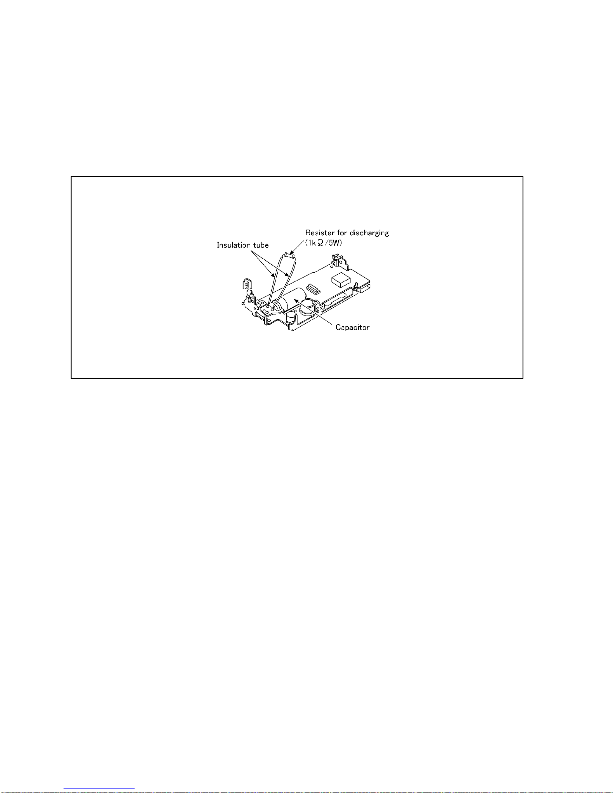
1.4. How to Discharge the Capacitor on Flash P.C.B.
CAUTION:
1. Be sure to discharge the capacitor on FLASH P.C.B..
2. Be careful of the high voltage circuit on FLASH P.C.B. when servicing.
[Discharging Procedure]
1. Refer to the disassemble procedure and Remove the necessary parts/unit.
2. Put the insulation tube onto the lead part of Resistor (ERG5SJ102:1kΩ /5W).
(an equivalent type of resistor may be used.)
3. Put the resistor between both terminals of capacitor on FLASH P.C.B. for approx. 5 seconds.
4. After discharging confirm that the capacitor voltage is lower than 10V using a voltmeter.
Fig. F1
5
2Warning
2.1. Prevention of Electrostatic Discharge (ESD) to Electrostatically
Sensitive (ES) Devices
Some semiconductor (solid state) devices can be damaged easily by static electricity. Such components commonly are called Electrostatically Sensitive (ES) Devices. Examples of typical ES devices are integrated circuits and some field-effect transistors and
semiconductor "chip" components. The following techniques should be used to help re duce the incidence of component damage
caused by electrostatic discharge (ESD).
1. Immediately before handling any semiconductor component or semiconductor-equipped assembly, drain off any ESD on your
body by touching a known earth ground. Alternatively, obtain and wear a commercially available discharging ESD wrist strap,
which should be removed for potential shock reasons prior to applying power to the unit under test.
2. After removing an electrical assembly equipped with ES devices, place the assembly on a conductive surface such as al uminum foil, to prevent electrostatic charge buildup or exposure of the assembly.
3. Use only a grounded-tip soldering iron to solder or unsolder ES devices.
4. Use only an antistatic solder removal device. Some solder removal devices not classified as "antistatic (ESD protected)" can
generate electrical charge sufficient to damage ES devices.
5. Do not use freon-propelled chemicals. These can generate electrical charges sufficient to damage ES devices.
6. Do not remove a replacement ES device from its protective package until immediately before you are ready to install it. (Most
replacement ES devices are packaged with leads electrically shorted together by conductive foam, aluminum foil or comparable conductive material).
7. Immediately before removing the protective material from the leads of a replacement ES device, touch the protective material
to the chassis or circuit assembly into which the device will be installed.
CAUTION :
Be sure no power is applied to the chassis or circuit, and observe all other safety precautions.
8. Minimize bodily motions when handling unpackaged replacement ES devices. (Otherwise harmless motion such as the
brushing together of your clothes fabric or the lifting of your foot from a carpeted floor can generate static electricity (ESD) sufficient to damage an ES device).
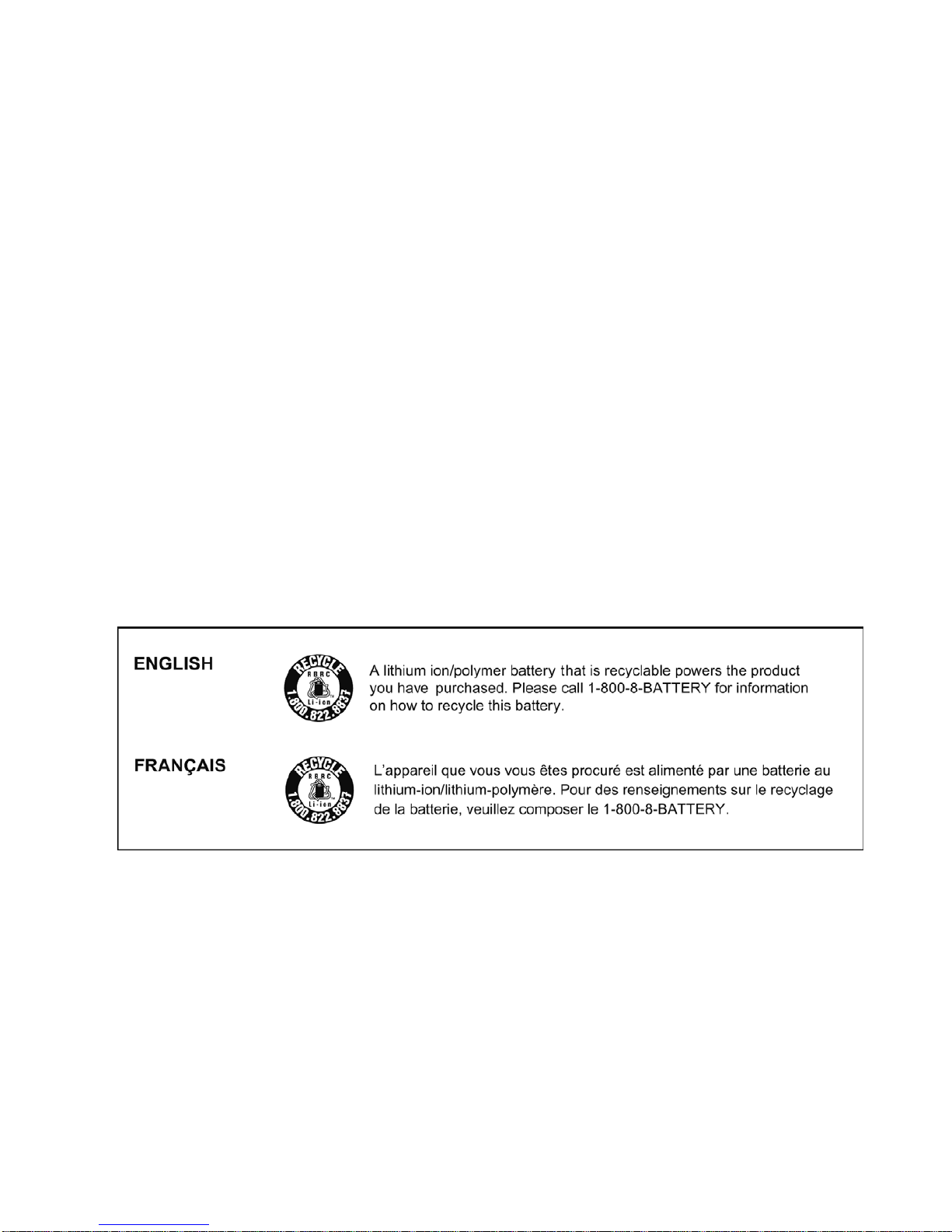
2.2. How to Recycle the Lithium Ion Battery (U.S. Only)
6
2.3. Caution for AC Cord
(For EB/GC)
2.3.1. Information for Your Safety
IMPORTANT
Your attention is drawn to the fact that recording of prerecorded tapes or discs or other published or broadcast
material may infringe copyright laws.
WARNING
To redu ce the risk of fire or shock hazard, do not expose
this equipment to rain or moisture.
CAUTION
To reduce the risk of fire or shock hazard and annoying
interference, use the recommended accessories only.
FOR YOUR SAFETY
DO NOT REMOVE THE OUTER COVER
To prevent electric shock, do not remove the cover. No user
serviceable parts inside. Refer servicing to qualified service
personnel.
2.3.2. Caution for AC Mains Lead
For your safety, please read the following text carefully.
This appliance is supplied with a moulded three-pin mains plug
for your safety and convenience.
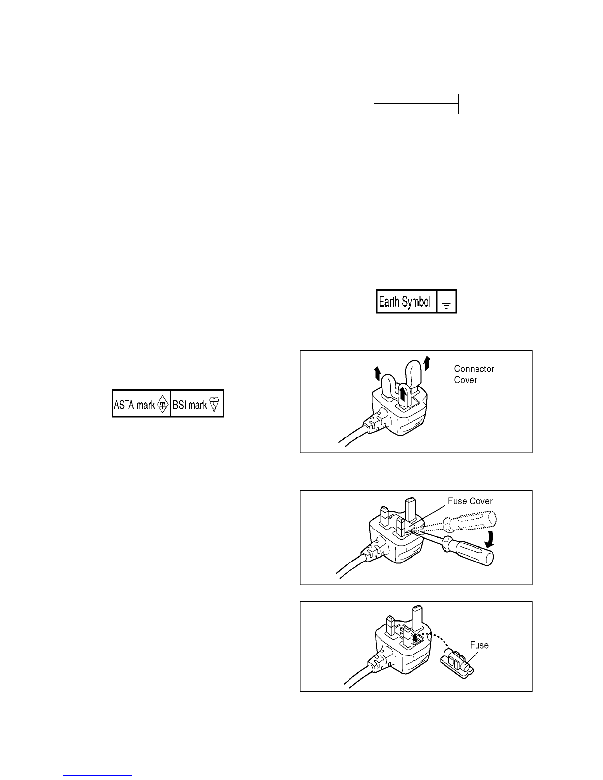
A 5-ampere fuse is fitted in this plug.
Should the fuse need to be replaced please ensure that the
replacement fuse has a rating of 5 amperes and it is approved
by ASTA or BSI to BS1362
Check for the ASTA mark or the BSI mark on the body of the
fuse.
If the plug contains a removable fuse cover you must ensure
that it is refitted when the fuse is replaced.
If you lose the fuse cover, the plug must not be used until a
replacement cover is obtained.
A replacement fuse cover can be purchased from your local
Panasonic Dealer.
If the fitted moulded plug is unsuitable for the socket outlet in
your home then the fuse should be removed and the plug cut
off and disposed of safety.
There is a danger of severe electrical shock if the cut off plug is
inserted into any 13-ampere socket.
If a new plug is to be fitted please observe the wiring code as
shown below.
If in any doubt, please consult a qualified electrician.
2.3.2.1. Important
The wires in this mains lead are coloured in accordance with
the following code:
As the colours of the wires in the mains lead of this appliance
may not correspond with the coloured markings i dentifying the
terminals in your plug, proceed as follows:
The wire which is coloured BLUE must be connected to the terminal in the plug which is marked with the le tter N or coloured
BLACK.
The wire which is coloured BROWN must be connected to the
terminal in the plug which is marked with the letter L or coloured
RED.
Under no circumstances should either of these wires be connected to the earth terminal of the three pin plug, marked with
the letter E or the Earth Symbol.
2.3.2.2. Before Use
Remove the Connector Cover as follows.
2.3.2.3. How to Replace the Fuse
1. Remove the Fuse Cover with a screwdriver.
2. Replace the fuse and attach the Fuse cover.
Blue Neutral
Brown Live
7
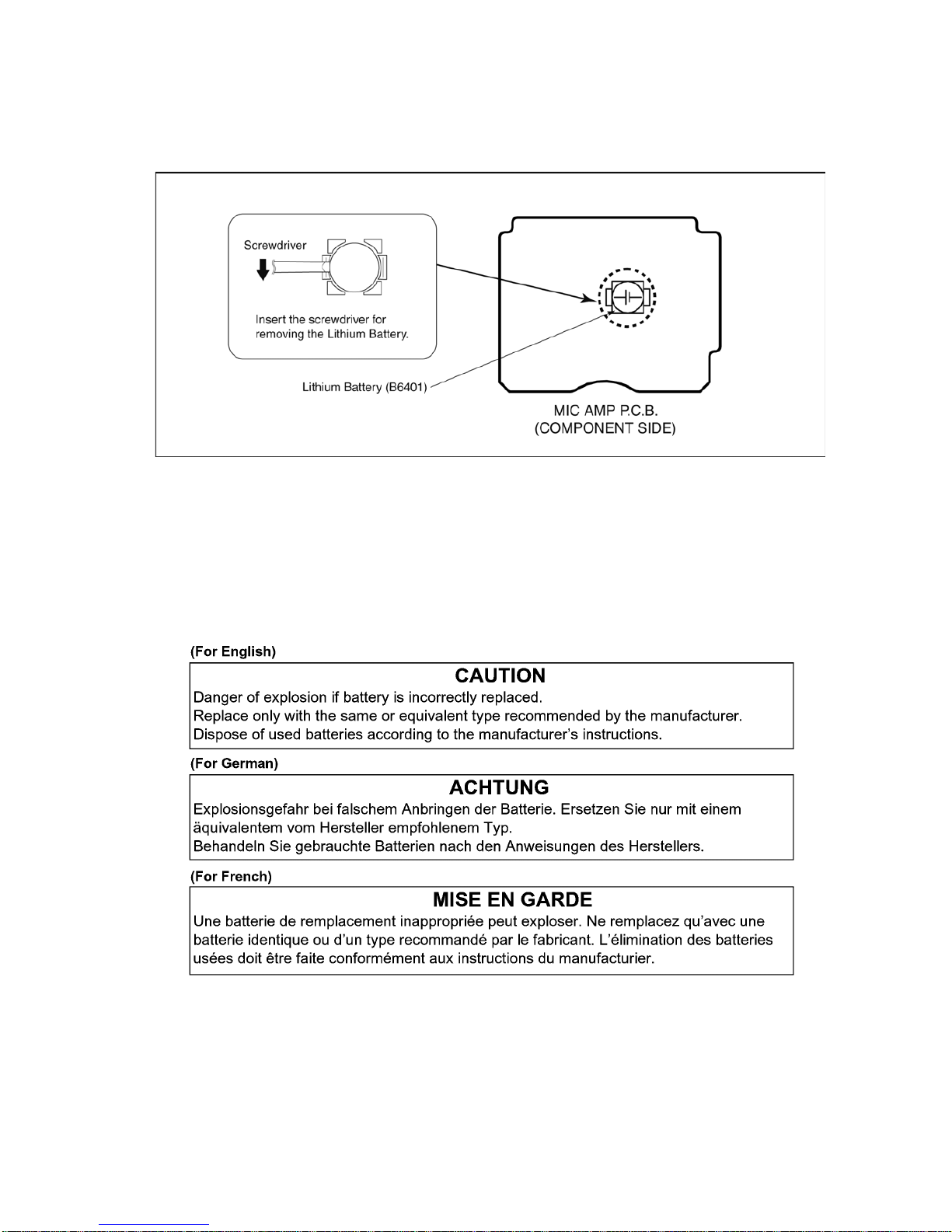
2.4. How to Replace the Lithium Battery
2.4.1. Replacement Procedure
1. Remove the MIC AMP P.C.B.. (Refer to Disassembly Procedures.)
2. Remove the Lithium battery (Ref. No. “B6401” at component side of MIC AMP P.C.B.) and then replace it into new one.
NOTE:
This Lithium battery is a critical component.
(Type No.: ML-614S/ZTK Manufactured by Energy Company, Panasonic Cor po ration)
It must never be subjected to excessive heat or discharge.
It must therefore only be fitted in requirement designed specifically for its use.
Replacement batteries must be of same type and manufacture.
They must be fitted in the same manner and location as the original battery, with the correct polarity contacts observed.
Do not attempt to re-charge the old battery or re-use it for any other purpose.
It should be disposed of in waste products destined for burial rather than incineration.
NOTE:
Above caution is applicable for a battery pack which is for HDC-SDT750/TMT750 series, as well.
1. Battery Pack for this model.
2. Button-type battery for Remote controller (CR2025: Being supplied from Energy Company, Panasonic Corporation).
8
3 Service Navigation
3.1. Introduction
This service manual contains technical information, which allow service personnel’s to understand and service this model.
Please place orders using the parts list and not the drawing reference numbers.
If the circuit is changed or modified, the information will be followed by service manual to be controlled with original service manual.
3.2. General Description About Lead Free Solder (PbF)
The lead free solder has been used in the mounting process of all electrical compone nts on the printed circuit bo ards used for this
equipment in considering the globally environmental conservation.
The normal solder is the alloy of tin (Sn) and lead (Pb). On the other hand, the lead free solder is the alloy mainly consists of tin
(Sn), silver (Ag) and Copper (Cu), and the melting point of the lead free solder is higher approx.30°C (86°F) mo re than th at of the
normal solder.
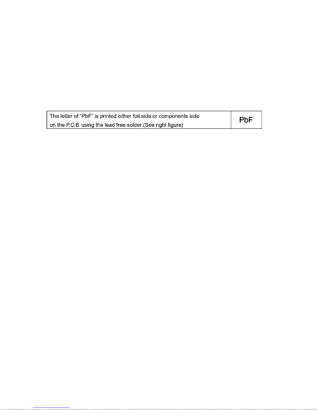
Distinction of P.C.B. Lead Free Solder being used
Service caution for repair work using Lead Free Solder (PbF)
• The lead free solder has to be used when repairing the equipment for which the lead free solder is used.
(Definition: The letter of “PbF” is printed on the P.C.B. using the lead free solder.)
• To put lead free solder, it should be well molten and mixed with the original lead free solder.
• Remove the remaining lead free solder on the P.C.B. cleanly for soldering of the new IC.
• Since the melting point of the lead free solder is high er than that of the normal lead solder, it takes the longer time to melt the
lead free solder.
• Use the soldering iron (more than 70W) equipped with the temperature control after setting the temperature at 350±30°C
(662±86°F).
Recommended Lead Free Solder (Service Parts Route.)
• The following 3 types of lead free solder are available through the service parts route.
RFKZ03D01KS-----------(0.3mm 100g Reel)
RFKZ06D01KS-----------(0.6mm 100g Reel)
RFKZ10D01KS-----------(1.0mm 100g Reel)
Note
* Ingredient: tin (Sn) 96.5%, silver (Ag) 3.0%, Copper (Cu) 0.5%, Cobalt (Co) / Germanium (Ge) 0.1 to 0.3%
3.3. Important Notice 1:(Other than U.S.A. and Canadian Market)
1. The service manual does not contain the following information, because of the impossibility of servi cing at component level
without concerned equipment/facilities.
a. Schematic diagram, Block Diagram and P.C.B. layout of MAIN P.C.B..
b. Parts list for individual parts for MAIN P.C.B..
When a part replacement is required for repairing MAIN P.C.B., replace as an assembled parts. (Main P.C.B.)
2. The following category is /are recycle module part. Please send it/them to Central Repair Center.
• MAIN P.C.B. (VEP03J02CN: HDC-SDT750PP)
• MAIN P.C.B. (VEP03J02CP: HDC-SDT750EB/EF/EG/EP)
• MAIN P.C.B. (VEP03J02CQ: HDC-SDT750EE/GC)
• MAIN P.C.B. (VEP03J02DN: HDC-TMT750GD/GT)
• MAIN P.C.B. (VEP03J02DQ: HDC-TMT750GC/GK)
9
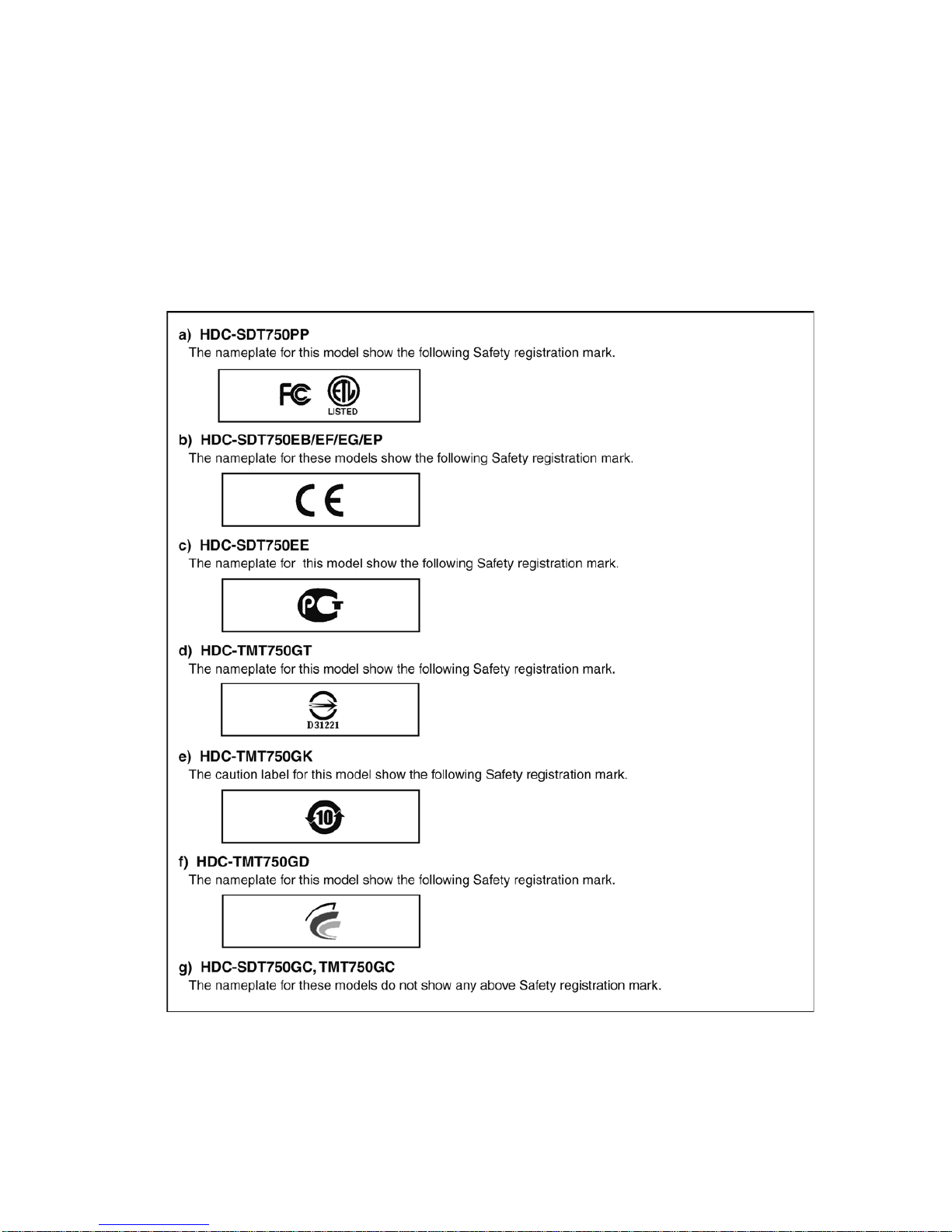
3.4. How to Define the Model Suffix (NTSC or PAL model)
There are seven kinds of HDC-SDT750/TMT750.
• a) HDC-SDT750PP
• b) HDC-SDT750EB/EF/EG/EP
• c) HDC-SDT750EE
• d) HDC-TMT750GT
• e) HDC-TMT750GK
• f) HDC-TMT750GD
• g) HDC-SDT750GC, TMT750GC
What is the difference is that the “INITIAL SETTING” data which is stored in Flash ROM mounted on Main P.C.B..
3.4.1. Defining methods:
To define the model suffix to be serviced, refer to the rating label and caution label which are putted on the Unit.
NOTE:
After replacing the MAIN P.C.B., be sure to achieve adjustment.
The adjustment instruction is available at “software download” on the “Support Information from NWBG/VDBG-A VC” web-site in
“TSN system”, together with Maintenance software.
10
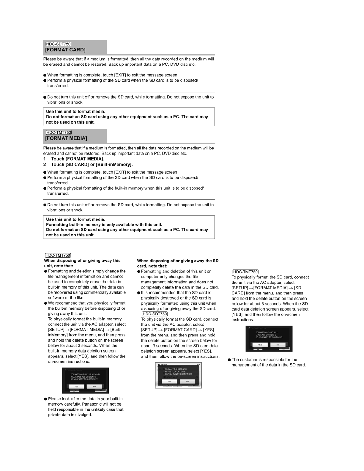
3.5. Formatting

11
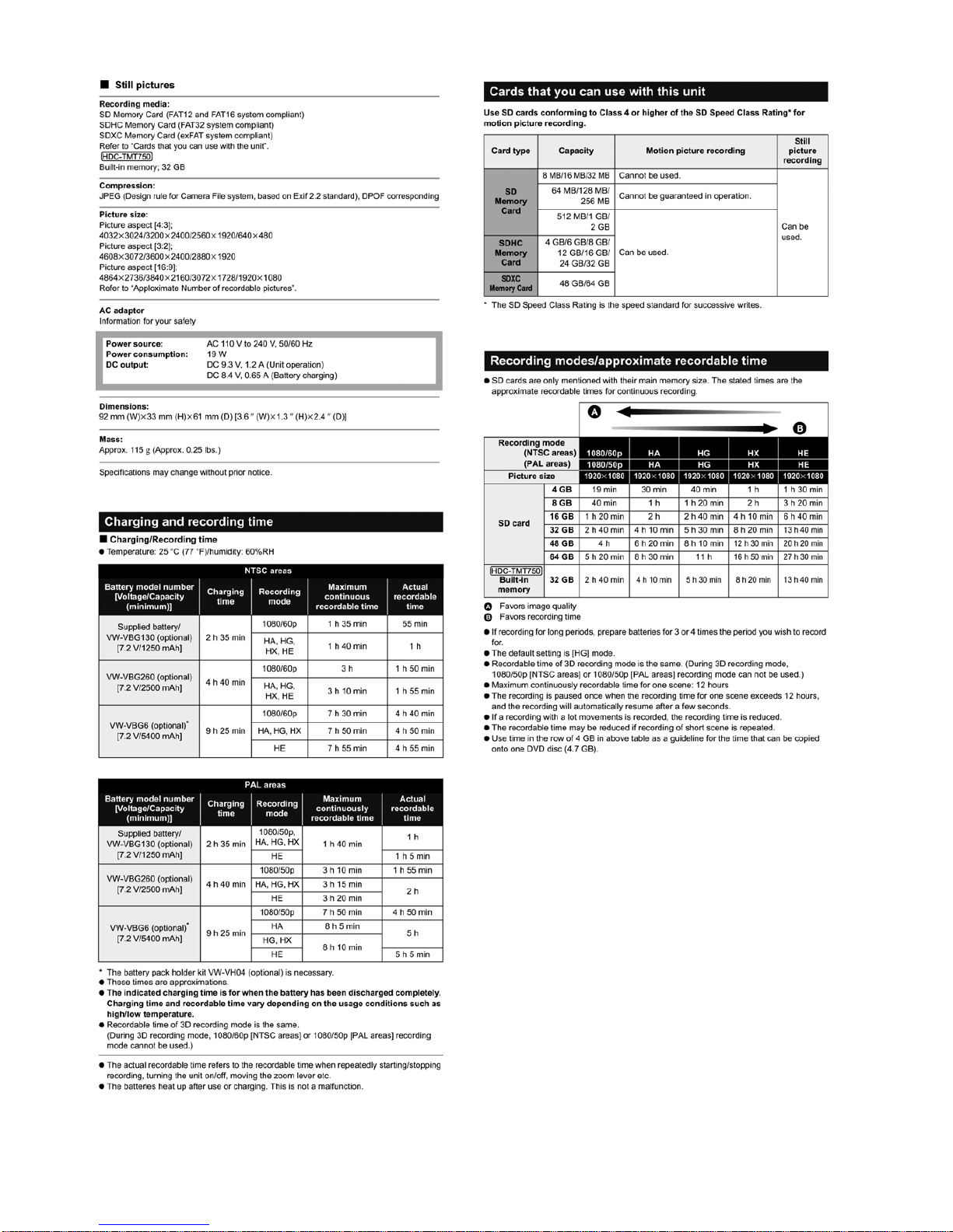
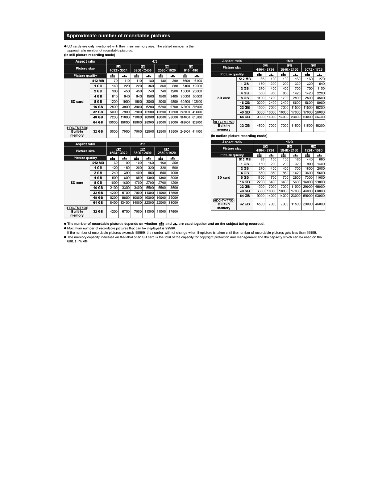
4 Specifications
12
13
14
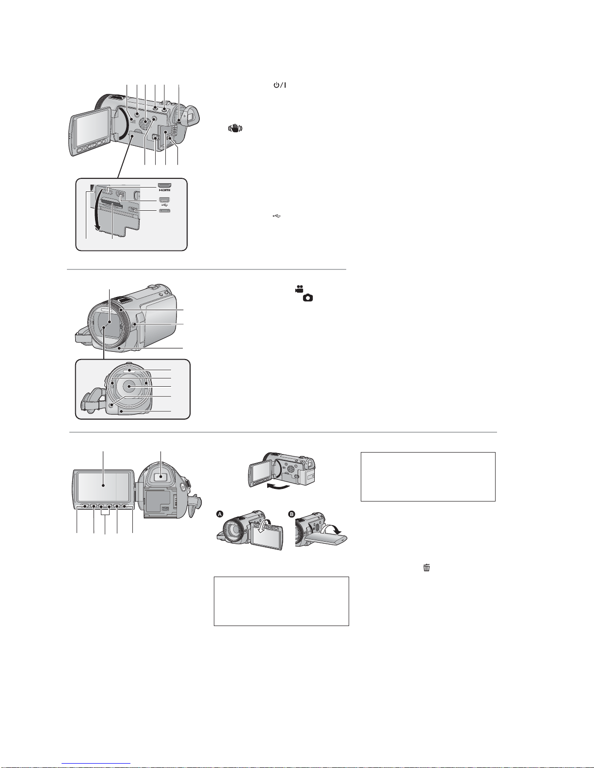
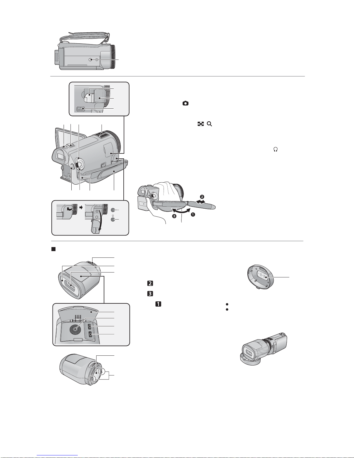
5 Location of Controls and Components
1 Speaker
2 Power button [ ]
3 Inlet (cooling fan)
4 Intelligent auto/Manual button
[iA/MANUAL]
5 Optical image stabilizer button
[ O.I.S.]
6 Eyepiece corrector dial
7 1080/60p button [1080/60p] (NTSC areas)
1080/50p button [1080/50p] (PAL areas)
8 Battery release lever [BATT]
9 Battery holder
10 DC input terminal [DC IN]
●
Always use the supplied AC adaptor or a
genuine Panasonic AC adaptor.
11 HDMI mini connector [HDMI]
12 USB terminal [ ]
13 AV multi connector
●
Use the AV multi cable (only the supplied
cable).
14 Card slot
15 Access lamp [ACCESS]
16 Lens cover
●
The lens cover opens in Motion
Picture Recording Mode or Still
Picture Recording Mode.
17 Multi manual ring
18 Camera function button
[CAMERA FUNCTION]
19 Remote control sensor
20 Built-in flash
21 3D Conversion Lens attachment part
(concave)
22 Lens (LEICA DICOMAR)
23 AF assist lamp
24 Recording lamp
1089
2
3
4
5
6
7
11
12
13
1
5141
16
17
18
19
20
22
21
23
24
25 LCD monitor (Touch screen)
●
It can open up to 90Q.
●
It can rotate up to 180Q towards the lens
or 90Qtowards the viewfinder.
26 Viewfinder
27 Quick menu button [Q.MENU]
28 Sub recording start/stop button
●
This button functions in the same manner
as the recording start/stop button.
29 Adjust zoom buttons
30 Menu button [MENU]
31 Delete button [ ]
25 26
28
27 29 30 31
Due to limitations in LCD production
technology, there may be some tiny bright
or dark spots on the LCD monitor screen.
However, this is not a malfunction and
does not affect the recorded picture.
Due to limitations in LCD production
technology, there may be some tiny bright
or dark spots on the viewfinder screen.
However, this is not a malfunction and
does not affect the recorded picture.
15
32 Tripod receptacle
32
33 Shoe adaptor mount
34 Shoe adaptor cover
35 Shoe adaptor release lever
[SHOE ADAPTOR RELEASE]
36 Photoshot button [ ]
37 Zoom lever [W/T] (In Motion Picture
Recording Mode or Still Picture
Recording Mode)
Thumbnail display switch [ / ]/
Volume lever [UVOLT] (In Playback
Mode)
38 Status indicator
39 Internal microphones
40 Recording start/stop button
41 Mode dial
42 Shoulder strap fixture
43 Grip belt
Adjust the length of the grip belt so that it fits
your hand.
Flip the belt.
Adjust the length.
Replace the belt.
44 Microphone terminal [MIC]
●
A compatible plug-in powered microphone
can be used as an external microphone.
●
Audio will be stereo (2 ch) with the
external microphone input.
●
When the unit is connected with the AC
adaptor, sometimes noise may be heard
depending on the microphone type. In this
case, please switch to the battery for the
power supply and the noise will stop.
45 Headphone terminal [ ]
MIC
33
34
35
396373
40 41 42 43
44
45
38
About the 3D Conversion Lens
1 Attachment screw
2 Protective glass (front)
3Lens
4 Adjustment dial cover
5 Vertical position adjustment dial
[]
6 Vertical alignment adjustment dial
[]
7 Horizontal imageposition adjustment
dial [ ]
8 Protective glass (rear)
9 Camera body attachment part
(convex)
Lens front cap
10 Horizontal line for adjustment
Use to adjust the lens attachment position.
If you use the lens front cap as a stand as
shown below, you can leave the unit with
the 3D Conversion Lens attached.
1
3
2
4
5
6
7
8
9
10
16
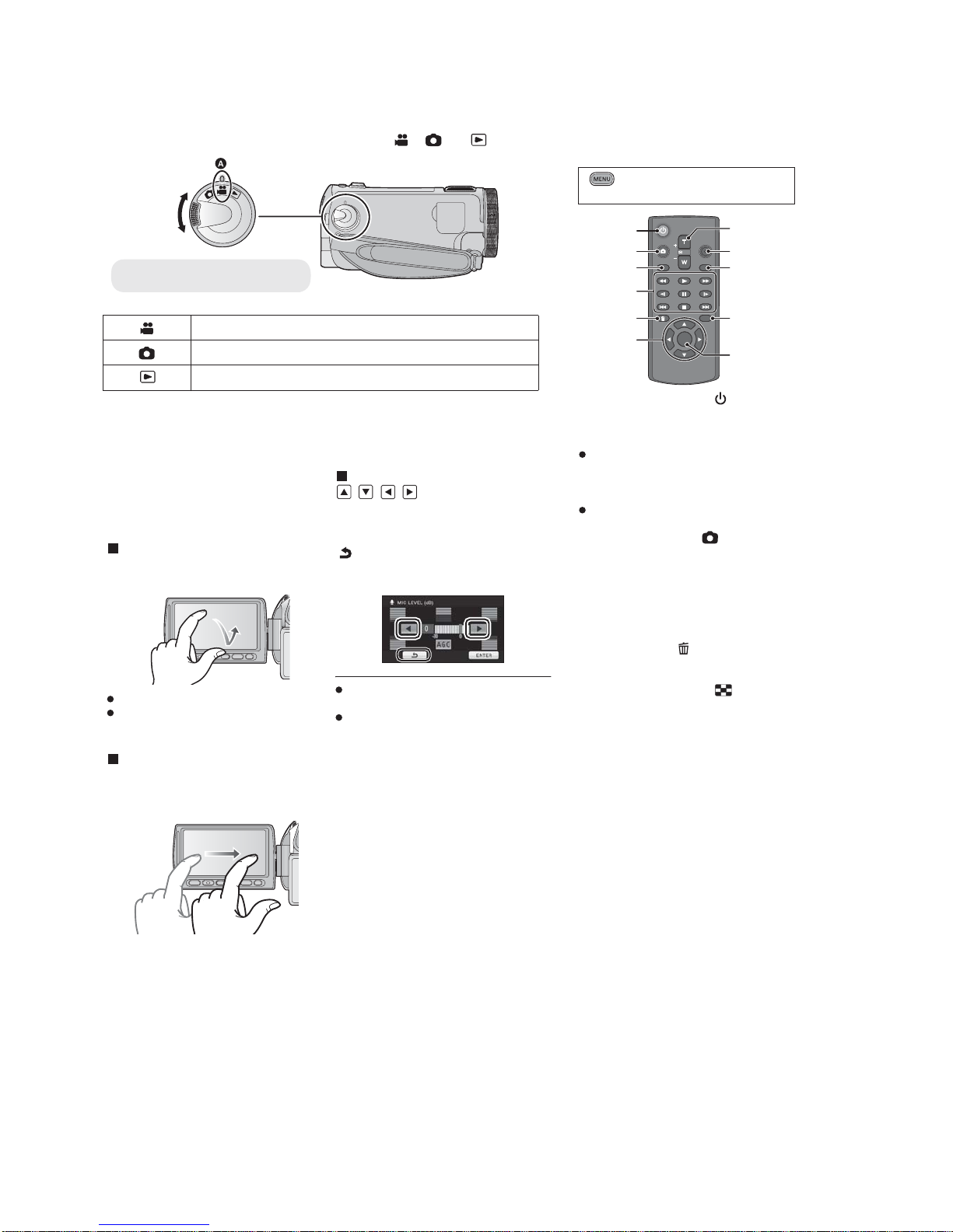
Selecting a mode
Change the mode to recording or playback.
Operate the mode dial to change the mode to , or .
Motion Picture Recording Mode
Still Picture Recording Mode
Playback Mode
●
Align with the status indicator .
How to use the touch screen
You can operate by directly touching the
LCD monitor (touch screen) with your finger.
It is easier to use the stylus pen (supplied)
for detailed operation or if it is hard to
operate with your fingers.
Touch
Touch and release the touch screen to select
icon or picture.
Touch the center of the icon.
Touching the touch screen will not operate
while you are touching another part of the
touch screen.
Drag
Move your finger while pressing on the touch
screen. Can be used during direct playback
and playback zoom.
About the operation icons
///:
These icons are used to switch the menu
and thumbnail display page, for item
selection and setting etc.
:
Touch to return to the previous screen
such as when setting menus.
Do not touch on the LCD monitor with
hard pointed tips, such as ball point pens.
Perform the touch screen calibration when
the touch is not recognized or wrong
location is recognized.
Using with the remote
control
Select the menu.
1 Power on/off button [ ]
Unit can be turned on/off when the LCD
monitor is opened or the viewfinder is
extended.
Unit cannot be turned on by the power on/
off button when 36 hours have passed after
the unit is turned off. Press the power
button on the unit and turn the unit back on.
Unit cannot be turned off when it is
connected to the PC or the DVD burner.
2 Photoshot button [ ]
*
3 On-screen display button
[EXT DISPLAY]
4 Playback operation buttons
These buttons function in the same manner
as the corresponding playback operation
icon being displayed on screen.
[Excluding skip playback]
5 Delete button [ ]
*
6 Direction buttons [,,,]
7 Zoom/volume/thumbnail display
switch buttons [T, W, /VOL]*
8 Recording start/stop button [START/
STOP]
*
9 Date/time button [DATE/TIME]
10 Menu button [MENU]
*
11 OK button [OK]
* means that these buttons function in the
same manner as the corresponding
buttons on the unit.
: [SETUP]
[REMOTE CONTROL] [ON]
SEARCH
STILL ADV STILL ADV
SEARCH
/VOL
DATE/TIME
START/
STOP
EXT DISPLAY
PLAY
STOP
OK
SKIP SKIP
MENU
PAUSE
2
3
4
6
5
8
7
9
10
11
1
17
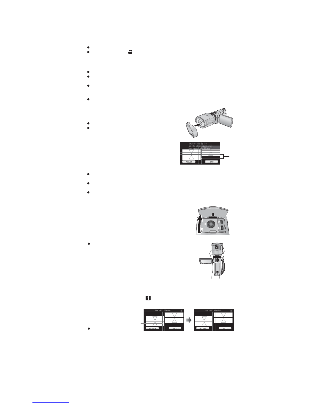
Recording 3D video
When using for the first time, be sure to adjust the 3D Conversion Lens attachment position.
Turn off the unit.
Change the mode to
.
1
Attach the 3D Conversion Lens to the unit.
2
Turn on the unit.
Turn on with the unit in a horizontal state.
The 3D Conversion Lens adjustment mode screen will appear automatically after
performing the initial setting.
If the 3D Conversion Lens adjustment mode screen does not appear automatically,
set from the menu.
([SETUP] [3D CONV. LENS SETUP])
If the unit is turned on with the USB cable still connected, the USB connection will take
priority.
3
Attach the lens front cap to the 3D
Conversion Lens.
2 screens will appear.
The horizontal line for adjustment on the lens front cap is
displayed on the screen.
Guide Line
4
Touch [ADJUST].
If the black vertical line and the black horizontal line are within the red guidelines and
adjustment is not required, touch [EXIT] and proceed to Step 11.
Perform the adjustment in a bright location where the horizontal line for adjustment will be
clearly visible.
The 3D Conversion Lens cannot be adjusted using the viewfinder.
5
Open the adjustment dial cover.
When turning the adjustment dials, hold the 3D Conversion
Lens in the palm of your hand from the bottom and operate
with the fingers of your other hand without applying too much
force from above. When checking the adjustment, check with
your fingers off the adjustment dials.
6
(After checking the operation description, touch [NEXT].)
To adjust the horizontal position, rotate the horizontal image
position adjustment dial so that the black vertical line is between
the red guidelines .
Touch [NEXT].
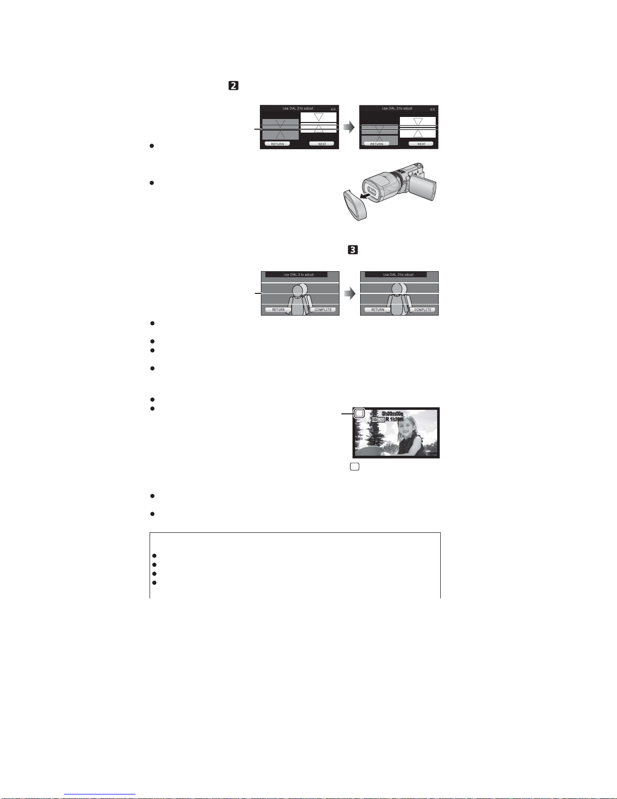
18
7
(After checking the operation description, touch [NEXT].)
To adjust the vertical position, rotate the vertical position
adjustment dial so that the black horizontal line at the right of the
screen is in the center of the red guidelines .
Touch [NEXT].
8
Removing the lens front cap.
Touch [NEXT].
9
(After checking the operation description, touch [NEXT].)
Adjust the vertical alignment adjustment dial to align the vertical
position of the subject shown duplicated.
Aim the unit at a subject from a distance of approximately 1.2 m (3.9 feet) to 2 m (6.6 feet),
and keep the image shown level by using the guidelines
.
Difference in horizontal direction is characteristic of 3D video.
It is recommended to stabilize the unit using the lens front cap as a platform when
performing the adjustment.
Touch [COMPLETE].
10
Touch [EXIT] to end the adjustment.
After adjustment, a single screen appears.
When re-attaching the 3D Conversion Lens or after
an impact etc., it is recommended that you perform
the adjustment again.
11
Press the recording start/stop button to start recording.
When the 3D Conversion Lens is attached, the zoom position is fixed, and the zoom
operation is disabled.
When recording in 3D, the image will appear with black frame around it. The black frame
will be recorded in the video.
7/8
7/8
To ensure that the 3D video can be safely viewed, pay attention to the following
points when recording.
Where possible, record with the unit in a horizontal state.
Do not get too close to the subject. (record from a distance of at least 1.2 m (3.9 feet).)
When moving the unit as you record, move it slowly.
Try to hold the unit as steady as possible when recording while riding in a vehicle or
walking.
3D
0h00m00s0h00m00s
R 1h20mR 1h20m
appears.
3D
19
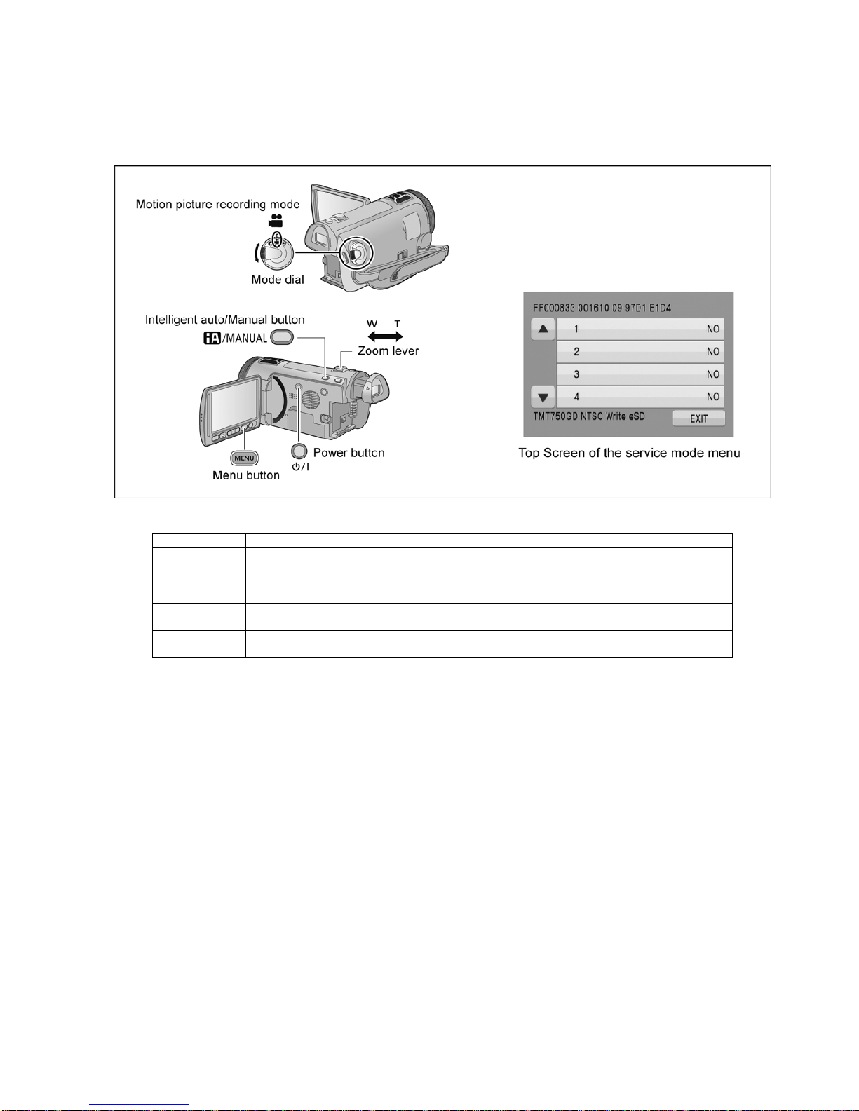
6 Service Mode
1. Indication method of the service menu
Set the mode dial “Motion Picture Recording” mode.
2. Turn the power on, and then while keep pressing the “Zoom lever” to W side, “Intelligent auto/Manual” button and “Menu” button for more than 3 seconds until the top screen of the Service Mode Menu being displayed.
Service mode menu
NOTE:
Do not using service mode except above table of Service mode menu.
3. End method of the top screen of the service mode menu
Push the “Menu” button to end the service mode, and then POWER OFF.
Screen display Contents Function
1 Factory settings Function to throw a product up in a factory shipment state
(When recorded data in Built-in memory, “error display” is done)
3 Built-in memory self check execution
(HDC-TMT750 only)
Function to check self as for the state of Built-in memory
4 Lock search history indication Display the camera system error cord for three histories saved
in EEPROM
5 Power ON self check result display Power ON self check (function to diagnose correct function of
the device and interface between devices) result display
20
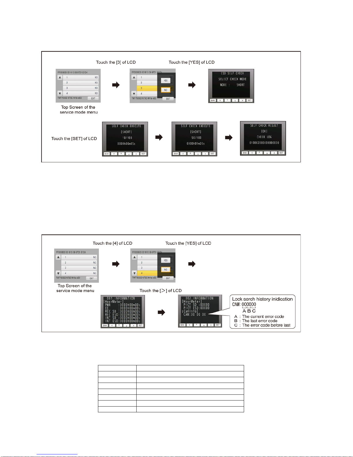
6.1. Built-in Memory Self Check Execution (HDC-TMT750 only)
Touch the [ 3 ] of LCD, select Built-in memory self check execution.
Operation specifications
Indication contents
• Built-in memory self check result display
Display the Built-in memory self check execution.
Displays other than “OK” are abnormalities of Built-in memory.
Push the “Menu” button to end the service mode, and then POWER OFF.
6.2. Lock Search History Indication
Touch the [ 4 ] of LCD, select Lock search history indication.
Operation specifications
Indication contents
• Lock search history indication
Display the camera system error cord for three histories saved in EEPROM.
• The error cord contents which are displayed
Push the “Menu” button to end the service mode, and then POWER OFF.
Error code Function
51 Focus control is abnormal
52 Zoom control is abnormal
53 OIS lens control is abnormal
71 Lens cover open/close is abnormal
72 Cooling fan is abnormal
73 High temperature is abnormal
33 Communication between camera to ARM is abnormal
21
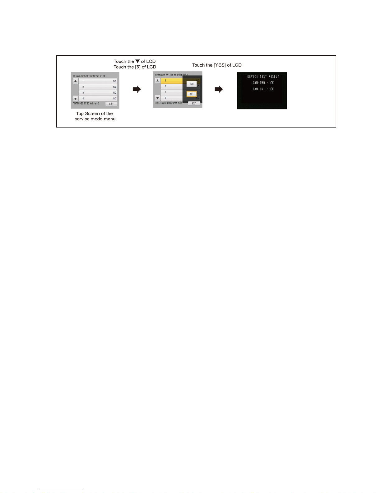
6.3. Power ON Self Check Result Display
Touch the [ 5 ] of LCD, select Power ON self check resul t di splay.
Operation specifications
Indication contents
• Power ON self check result display
Function to diagnose correct function of the device and interface between devices result display.
Display the following commnucation test result.
- CAM-PWR : Commnucation test between IC2006 to IC301
- CAM-UNI : Commnucation test between IC3401 to IC301
Display other than “OK” are abnomalities of each lines.
Cutting of battery connection or AC power supply connection to end the service mode.
22
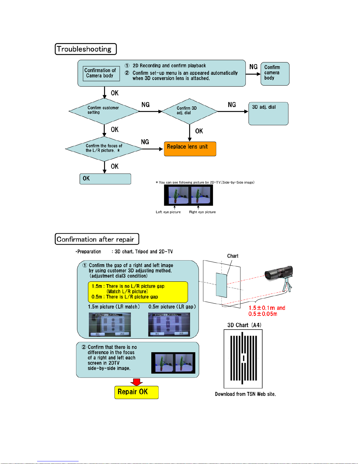
7 Troubleshooting Guide

23
8 Service Fixture & Tools
8.1. When Replacing the Main P.C.B.
After replacing the MAIN P.C.B., be sure to achieve adjustment.
The adjustment instruction is available at “software download” on the “Support Information from NWBG/VDBG-AVC” web-site in
“TSN system”, together with Maintenance software.
8.2. Service Position
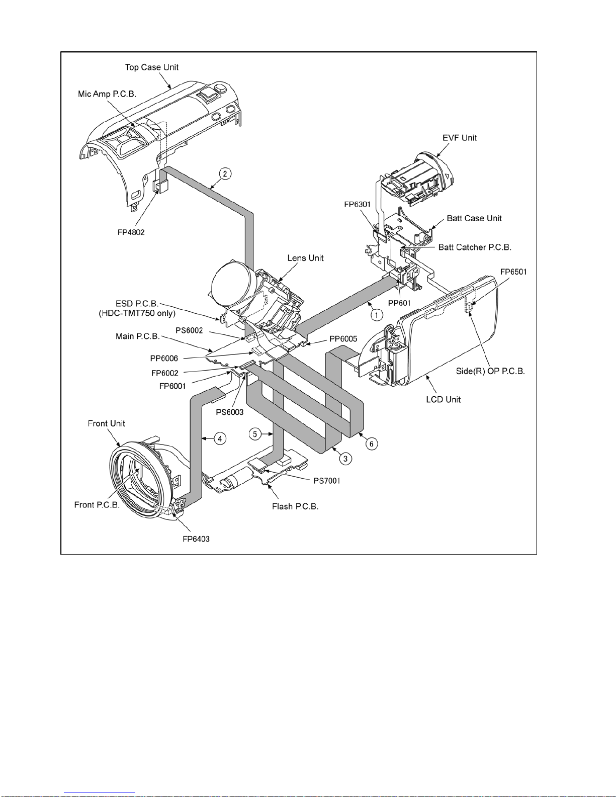
This Service Position is used for checking and replacing parts. Use the following Extension cables for servicing.
Table S1 Extension Cable List
No. Parts No. Connection Form
1 RFKZ0444 PP6005(MAIN) - PP601(BATT CATCHER) 50PIN 0.5 B to B
2 RFKZ0342 PS6002(MAIN) - FP4802(MIC AMP) 20PIN 0.5 B to B
3 VFK1933 PS6003(MAIN) - MONITOR FPC 34PIN 0.5 B to B
4 VFK1950 FP6001(MAIN) - FP6403(FRONT) 33PIN 0.3 FFC
5 RFKZ0343 PP6006(MAIN) - PS7001(FLASH) 30PIN 0.5 B to B
6 RFKZ0416 FP6002(MAIN) - LENS UNIT 41PIN 0.3 FFC
24
CAUTION-1. (When servicing FLASH P.C.B.)
1. Be sure to discharge the capacitor on FLASH P.C.B..
Refer to “HOW TO DISCHARGE THE CAPACITOR ON FLASH P.C.B.”.
The capacitor voltage is not lowered soon even if the AC Cord is unplugged or the battery is removed.
2. Be careful of the high voltage circuit on FLASH P.C.B..
3. DO NOT allow other parts to touch th e hi g h vol tage circuit on FLASH P.C.B..
25
9 Disassembly and Assembly Instructions
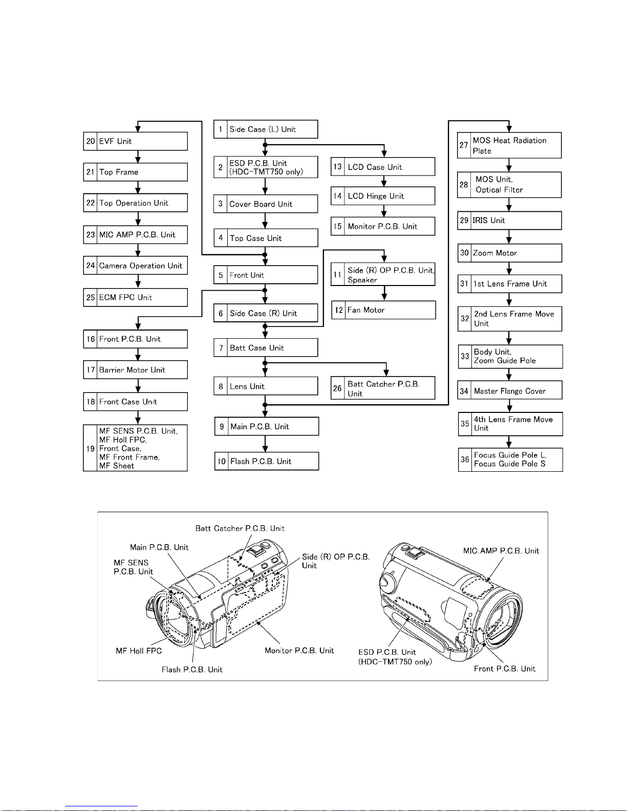
9.1. Disassembly Flow Chart for the Unit
This is a disassembling chart.
When assembling, perform this chart conversely.
9.2. PCB Location

26
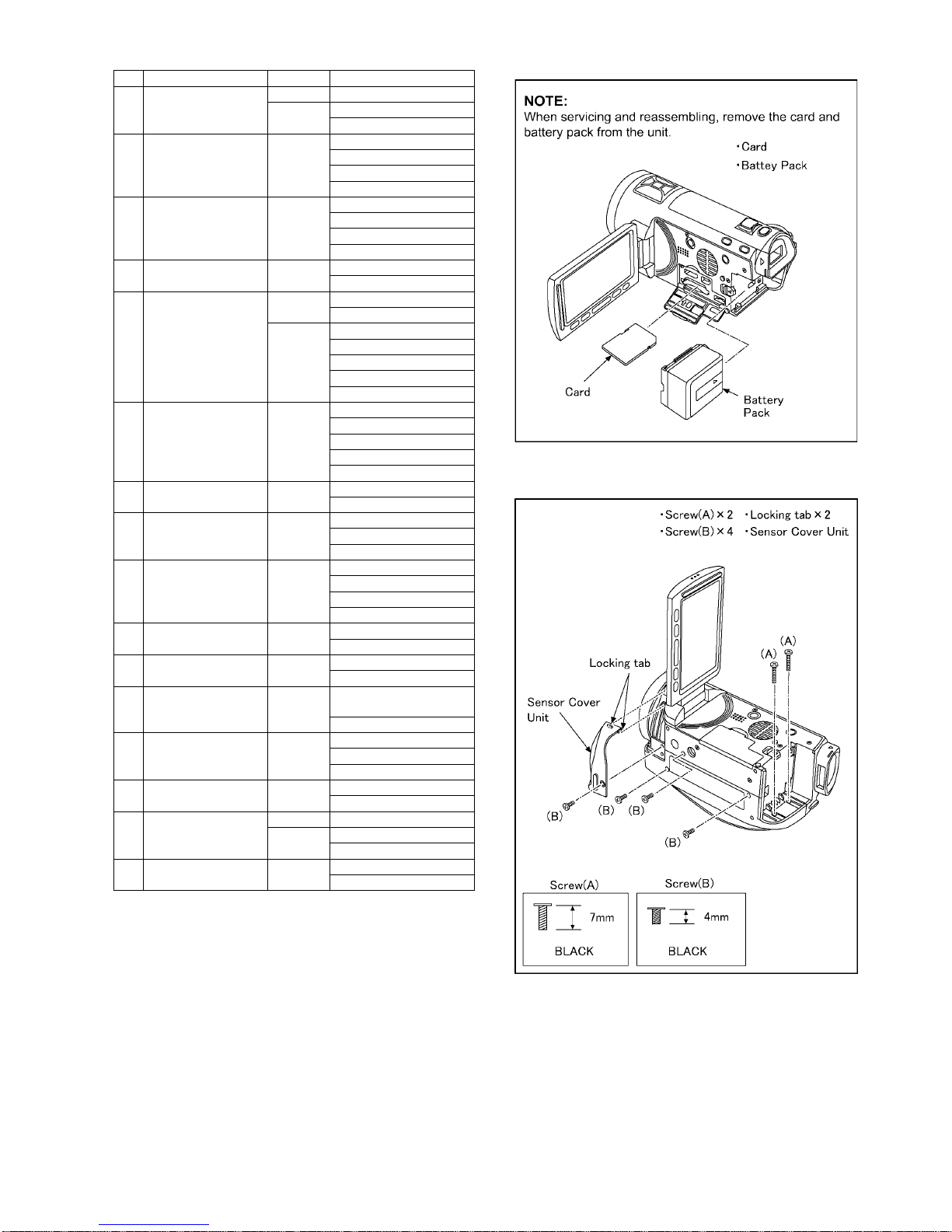
9.3. Disassembly Procedure for the
Unit
No. Item Fig Removal
1 Side Case (L) Unit Fig. D1 2 Screws (A)
4 Screws (B)
2 Locking tabs
Sensor Cover Unit
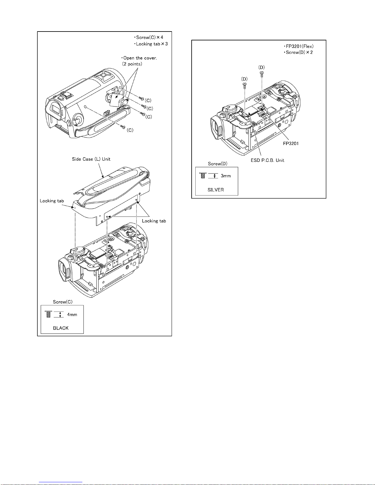
Fig. D2 4 Screws (C)
3 Locking tabs
Side Case (L) Unit
2ESD P.C.B. Unit
(HDC-TMT750 only)
Fig. D3 FP3201 (Flex)
2 Screws (D)
ESD P.C.B. Unit
3 Cover Board Unit Fig. D4 1 Screw (E)
2 Screws (F)
1 Rib
Cover Board Unit
4 Top Case Unit Fig. D5 2 Screws (G)
1 Screw (H)
1 Screw (I)
1 Screw (J)
2 Locking tabs
1 Rib
SR Cover
Fig. D6 PS6002 (Connector)
1 Rib
1 Locking tab
FP6301 (Flex)
Top Case Unit
5 Front Unit Fig. D7 P7001 (Connector)
P7002 (Connector)
1 Screw (K)
1 Rib
1 Locking tab
FP6403 (Flex)
Front Unit
6 Side Case (R) Unit Fig. D8 4 Screws (L)
1 Screw (M)
PS6003 (Connector)
FP6501 (Flex)
Side Case (R) Unit
7 Batt Case Unit Fig. D9 1 Screw (N)
1 Screw (O)
2 Ribs
PP6005 (Connector)
Batt Case Unit
8 Lens Unit Fig. D10 2 Screws (P)
1 Rib
2 Projection parts
Fig. D11 PP6004 (Connector)
PP6007 (Connector)
FP6002 (Flex)
1 Screw (Q)
Lens Frame Unit
Lens Unit
9 Main P.C.B. Unit Fig. D12 3 Screws (R)
2 Ribs
Main Heat Radiation Plate
Fig. D13 PP6006 (Connector)
1 Projection part
Main P.C.B. Unit
10 Flash P.C.B. Unit Fig. D14 2 Screws (S)
1 Projection part
Flash P.C.B. Unit
11 Side (R) OP P.C.B.
Unit
Speaker
Fig. D15 2 Screws (T)
SP Angle
PS6501 (Connector)
P6501 (Connector)
Speaker
Side (R) OP P.C.B. Unit
Fig. D16 NOTE: (When Installing)
12 Fan Motor Fig. D17 3 Convexes
Fan Damper
Fan Motor
13 LCD Case Unit Fig. D18 2 Screws (U)
Holder
Switch Unit
3 Locking tabs
Earth Plate
Sheet
Light Guide Plate
3 Ribs
LCD Case Unit
14 LCD Hinge Unit Fig. D19 2 Screws (V)
6 Locking tabs
LCD Case (T) Unit
FP901 (Flex)
FP902 (Flex)
LCD Hinge Unit
15 Monitor P.C.B. Unit Fig. D20 FP904 (Flex)
FP905 (Flex)
2 Ribs
2 Convexes
LCD Frame
Fig. D21 FP903 (Flex)
4 Locking tabs
Fig. D22 1 Locking tab
Reflection Sheet
Light Guide Plate
Diffusion Sheet
Prism Sheet B
Prism Sheet A
Lighting Plate Holder
Monitor P.C.B. Unit
16 Front P.C.B. Unit Fig. D23 1 Screw (W)
1 Screw (X)
FP6400 (Flex)
FP6402 (Flex)
Front P.C.B. Unit
17 Barrier Motor Unit Fig. D24 1 Screw (Y)
Barrier Motor Unit
Fig. D25 NOTE: (When Installing)
18 Front Case Unit Fig. D26 Lens Ornament Sheet
Fig. D27 4 Screws (Z)
Front Case Unit
19 MF SENS P.C.B. Unit
MF Holl FPC
Front Case
MF Front Frame
MF Sheet
Fig. D28 1 Screw (a)
1 Convex
2 Hooks
Fig. D29 MF P.C.B. Holder
P2701 (Flex)
MF SENS P.C.B. Unit
MF Holl FPC
Front Case
MF Front Frame
MF Sheet
Fig. D30 NOTE: (When Replacing)
20 EVF Unit Fig. D31 2 Screws (b)
1 Screw (c)
EVF Unit
No. Item Fig Removal
27
9.3.1. Removal of the Side Case (L) Unit
Fig. D1
21 Top Frame Fig. D32 4 Screws (d)
Fig. D33 1 Locking tab
Top Frame
22 Top Operation Unit Fig. D34 4 Screws (e)
FP4803 (Flex)
2 Ribs
Top Operation Unit
23 MIC AMP P.C.B. Unit Fig. D35 FP4801 (Flex)
FP4804 (Flex)
2 Hooks
MIC AMP P.C.B. Unit
24 Camera Operation Unit Fig. D36 2 Locking tabs
Camera Operation Unit
25 ECM FPC Unit Fig. D37 4 Locking tabs
MIC Sheet
Fig. D38 MIC Cushion (A)
MIC Cushion (B)
MIC Cushion (C)
MIC Case
ECM FPC Unit
26 Batt Catcher P.C.B.
Unit
Fig. D39 2 Screws (f)
2 Locking tabs
Rear Frame
2 Locking tabs
Batt Catcher P.C.B. Unit
27 MOS Heat Radiation
Plate
Fig. D40 1 Screw (g)
MOS Heat Radiation Plate
28 MOS Unit
Optical Filter
Fig. D41 2 Screws (h)
MOS Unit
Optical Filter
29 IRIS Unit Fig. D42 18 Solders
3 Screws (i)
3 Ribs
IRIS Unit
30 Zoom Motor Fig. D43 2 Screws (j)
Zoom Motor
31 1st Lens Frame Unit Fig. D44 3 Screws (k)
1st Lens Frame Unit
32 2nd Lens Frame Move
Unit
Fig. D45 2nd Lens Frame Move Unit
Spring
2nd Lens Frame Move Unit
33 Body Unit
Zoom Guide Pole
Fig. D46 3 Screws (l)
Body Unit
2 Zoom Guide Poles
34 Master Flange Cover Fig. D47 2 Screws (m)
Master Flange Cover
35 4th Lens Frame Move
Unit
Fig. D48 2 Side Yorks
Fig. D49 3 Ribs
4th Lens Frame Move Unit
36 Focus Guide Pole L
Focus Guide Pole S
Fig. D50 Focus Guide Pole L
Focus Guide Pole S
No. Item Fig Removal
28
Fig. D2
9.3.2. Removal of the ESD P.C.B. Unit
Fig. D3
 Loading...