

Panasonic HDC27F User Manual
AJ- P
Camera/VTR
Operating Instructions
2
indicates safety information.
CAUTION
RISK OF ELECTRIC SHOCK
DO NOT OPEN
CAUTION: TO REDUCE THE RISK OF ELECTRIC SHOCK,
DO NOT REMOVE COVER (OR BACK).
NO USER SERVICEABLE PARTS INSIDE.
REFER TO SERVICING TO QUALIFIED SERVICE PERSONNEL.
The lightning flash with arrowhead symbol,
within an equilateral triangle, is intended to
alert the user to the presence of uninsulated
“dangerous voltage” within the product’s
enclosure that may be of sufficient magnitude
to constitute a risk of electric shock to
persons.
The exclamation point within an equilateral
triangle is intended to alert the user to the
presence of important operating and
maintenance (service) instructions in the
literature accompanying the appliance.
WARNING:
TO REDUCE THE RISK OF FIRE OR SHOCK
HAZARD, DO NOT EXPOSE THIS
EQUIPMENT TO RAIN OR MOISTURE.
CAUTION:
TO REDUCE THE RISK OF FIRE OR SHOCK
HAZARD AND ANNOYING INTERFERENCE,
USE THE RECOMMENDED ACCESSORIES
ONLY.
CAUTION:
TO REDUCE THE RISK OF FIRE OR SHOCK
HAZARD, REFER CHANGE OF SWITCH
SETTING INSIDE THE UNIT TO QUALIFIED
SERVICE PERSONNEL.
FCC Note:
This device complies with Part 15 of the FCC Rules.
To assure continued compliance follow the attached
installation instructions and do not make any
unauthorized modifications.
This equipment has been tested and found to comply
with the limits for a class A digital device, pursuant to
Part 15 of the FCC Rules. These limits are designed
to provide reasonable protection against harmful
interference when the equipment is operated in a
commercial environment. This equipment generates,
uses, and can radiate radio frequency energy and, if
not installed and used in accordance with the
instruction manual, may cause harmful interference to
radio communications. Operation of this equipment in
a residential area is likely to cause harmful
interference in which case the user will be required to
correct the interference at his own expense.
Replace battery with part No. CR2032 only.
Use of another battery may present a risk of fire or
explosion.
Caution—Battery may explode if mistreated.
Do not recharge, disassemble or dispose of in fire.
ATTENTION:
The product you have purchased is powered by a
nickel cadmium battery which is recyclable. At the
end of it’s useful life, under various state and local
laws, it is illegal to dispose of this battery into your
municipal waste stream.
Please call 1-800-8-BATTERY for information on how
to recycle this battery.
Ni-Cd
RBRC
RBRC

3
Contents
Introduction . . . . . . . . . . . . . . . . . . . . . . . . . . . . . . .5
Features . . . . . . . . . . . . . . . . . . . . . . . . . . . . . . . . . .5
Features of the camera unit . . . . . . . . . . . . . . . . . .5
Features of the VTR unit . . . . . . . . . . . . . . . . . . . .7
System configuration . . . . . . . . . . . . . . . . . . . . . . .8
Parts and their functions . . . . . . . . . . . . . . . . . . . .9
Power supply section . . . . . . . . . . . . . . . . . . . . . . .9
Accessory mounting section . . . . . . . . . . . . . . . .10
Audio function section . . . . . . . . . . . . . . . . . . . . .11
Viewfinder section . . . . . . . . . . . . . . . . . . . . . . . .13
Shooting (recording)/playback function section . .14
Warning/status display section . . . . . . . . . . . . . . .19
Menu operation section . . . . . . . . . . . . . . . . . . . .20
Time code related section . . . . . . . . . . . . . . . . . .20
Power supply . . . . . . . . . . . . . . . . . . . . . . . . . . . . .22
Using the Anton/Bauer battery pack . . . . . . . . . .22
Using the BP-90 type battery pack . . . . . . . . . . . .23
Using the Sony NP-1/BP-90 battery pack . . . . . .24
Using the V-mount type battery pack . . . . . . . . . .24
Using an AC power supply
when the AJ-B75 AC adapter is used . . . . . . . . .25
Attaching the lens . . . . . . . . . . . . . . . . . . . . . . . . .26
Adjusting the lens flange . . . . . . . . . . . . . . . . . . .27
Adjusting the white shading . . . . . . . . . . . . . . . . .28
Adjusting the viewfinder . . . . . . . . . . . . . . . . . . . .30
Attaching the viewfinder . . . . . . . . . . . . . . . . . . . .30
Detaching the viewfinder . . . . . . . . . . . . . . . . . . .30
Adjusting the viewfinder position . . . . . . . . . . . . .31
Audio input preparation . . . . . . . . . . . . . . . . . . . .32
When attaching a microphone to the viewfinder
(optional accessory) for use . . . . . . . . . . . . . . . . .32
When attaching a microphone to the main unit for
use . . . . . . . . . . . . . . . . . . . . . . . . . . . . . . . . . . . .33
When connecting a microphone to the
MIC IN jack . . . . . . . . . . . . . . . . . . . . . . . . . . . . . .34
When connecting a microphone to the
AUDIO IN connector . . . . . . . . . . . . . . . . . . . . . .34
When using a wireless microphone . . . . . . . . . . .35
When connecting audio components . . . . . . . . . .35
Mounting the unit on a tripod . . . . . . . . . . . . . . . .36
Attaching the shoulder strap . . . . . . . . . . . . . . . .37
Adjusting the shoulder pad position . . . . . . . . . .37
Attaching the rain cover . . . . . . . . . . . . . . . . . . . .38
Connecting the extension control unit . . . . . . . .38
Viewfinder lamp displays . . . . . . . . . . . . . . . . . . .39
Setting the lamp displays . . . . . . . . . . . . . . . .40
Viewfinder screen status displays . . . . . . . . . . . .41
Selecting the display items . . . . . . . . . . . . . . . . . .43
Display modes and setting change messages . . .45
Switching the display mode . . . . . . . . . . . . . . . . .46
Setting the marker displays . . . . . . . . . . . . . . . . .46
Setting the camera ID . . . . . . . . . . . . . . . . . . . . .47
Screen displays . . . . . . . . . . . . . . . . . . . . . . . . . . .48
Remaining battery charge and audio channel level
and remaining tape displays . . . . . . . . . . . . . . . .48
Displays relating to errors and warnings . . . . . . .48
Displays relating to time codes . . . . . . . . . . . . . .48
Adjusting the date and time . . . . . . . . . . . . . . . . .49
Adjustments and setup using the setting
menus . . . . . . . . . . . . . . . . . . . . . . . . . . . . . . . . .49
Adjusting the white balance and black
balance . . . . . . . . . . . . . . . . . . . . . . . . . . . . . . . . . .50
Adjusting the white balance . . . . . . . . . . . . . . . . .50
Adjusting the black balance . . . . . . . . . . . . . . . . .54
Setting the electronic shutter . . . . . . . . . . . . . . . .55
Shutter modes . . . . . . . . . . . . . . . . . . . . . . . . . . .55
Registering the shutter speed . . . . . . . . . . . . . . .55
Setting the shutter mode and speed . . . . . . . . . .56
Changing the shutter speed and mode selection
range . . . . . . . . . . . . . . . . . . . . . . . . . . . . . . . . . .56
Setting the synchro scan mode . . . . . . . . . . . . . .57
Switching the shutter speed display . . . . . . . . . . .57
Film tone gamma function . . . . . . . . . . . . . . . . . .58
Switching the frame frequency . . . . . . . . . . . . . .58
Variable frame rate . . . . . . . . . . . . . . . . . . . . . . . .59
Setting the frame rate . . . . . . . . . . . . . . . . . . . . . .59
Scan reverse . . . . . . . . . . . . . . . . . . . . . . . . . . . . .61
Setting the scan reverse . . . . . . . . . . . . . . . . . . .61
Adjusting the audio level . . . . . . . . . . . . . . . . . . .61
Manual audio level adjustments . . . . . . . . . . . . . .61
Limiter . . . . . . . . . . . . . . . . . . . . . . . . . . . . . . . . .61
Setting the time data . . . . . . . . . . . . . . . . . . . . . . .62
Setting the user’s bit . . . . . . . . . . . . . . . . . . . . . . .62
Setting the time code . . . . . . . . . . . . . . . . . . . . . .63
Externally locking the time code . . . . . . . . . . . . . .64
Tape management information . . . . . . . . . . . . . .65
How to use the user data . . . . . . . . . . . . . . . . . . .66
How to use the scene file . . . . . . . . . . . . . . . . . . .67
Setup card operations . . . . . . . . . . . . . . . . . . . . . .72
Formatting the setup card . . . . . . . . . . . . . . . . . .73
Saving the data settings on the card . . . . . . . . . .74
Loading the data saved on the card . . . . . . . . . . .76
Cassette tapes . . . . . . . . . . . . . . . . . . . . . . . . . . . .78
Recording . . . . . . . . . . . . . . . . . . . . . . . . . . . . . . . .79
Shooting . . . . . . . . . . . . . . . . . . . . . . . . . . . . . . . .80
Scene-to-scene continuity . . . . . . . . . . . . . . . . . .81
Playback
(checking what has been recorded) . . . . . . . . . . .82
Rec review . . . . . . . . . . . . . . . . . . . . . . . . . . . . . .82
Color playback . . . . . . . . . . . . . . . . . . . . . . . . . . .82
Lens RET button functions . . . . . . . . . . . . . . . . . .82
Other VTR functions . . . . . . . . . . . . . . . . . . . . . . .83
NEWS REC function . . . . . . . . . . . . . . . . . . . . . .83
RETAKE function . . . . . . . . . . . . . . . . . . . . . . . . .83
INTERVAL REC (intermittent recording)
function . . . . . . . . . . . . . . . . . . . . . . . . . . . . . . . . .83

4
Contents
Menu operations . . . . . . . . . . . . . . . . . . . . . . . . . .84
Basic setting menu operations . . . . . . . . . . . . . . .85
Displaying sub-menus and deciding on
settings . . . . . . . . . . . . . . . . . . . . . . . . . . . . . . . . .86
Setting menu configuration . . . . . . . . . . . . . . . . .87
Setting menu screens . . . . . . . . . . . . . . . . . . . . . .91
<FILM (CAM) MENUS>
FILM (CAM) MAIN MENU 1 screen . . . . . . . . . . .91
FILM (CAM) MAIN MENU 2 screen . . . . . . . . . . .91
FILM (CAM) MAIN MENU 3 screen . . . . . . . . . . .91
FILM (CAM) MAIN MENU 4 screen . . . . . . . . . . .91
FILM (CAM) MAIN MENU 1
ROP screen . . . . . . . . . . . . . . . . . . . . . . . . . . . . .92
MATRIX screen . . . . . . . . . . . . . . . . . . . . . . . . . .92
COLOR CORRECTION 1 screen . . . . . . . . . . . .93
COLOR CORRECTION 2 screen . . . . . . . . . . . .93
LOW SETTING screen . . . . . . . . . . . . . . . . . . . . .94
MID SETTING screen . . . . . . . . . . . . . . . . . . . . .94
HIGH SETTING screen . . . . . . . . . . . . . . . . . . . .95
ADDITIONAL DTL1 screen . . . . . . . . . . . . . . . . .95
ADDITIONAL DTL2 screen . . . . . . . . . . . . . . . . .95
SKIN TONE DTL screen . . . . . . . . . . . . . . . . . . .96
KNEE/LEVEL screen . . . . . . . . . . . . . . . . . . . . . .96
GAMMA screen . . . . . . . . . . . . . . . . . . . . . . . . . .97
CAMERA SETTING screen . . . . . . . . . . . . . . . . .97
FILM (CAM) MAIN MENU 2
VF DISPLAY screen . . . . . . . . . . . . . . . . . . . . . . .98
VF MARKER screen . . . . . . . . . . . . . . . . . . . . . .99
VF INDICATOR screen . . . . . . . . . . . . . . . . . . . .99
CAMERA ID screen . . . . . . . . . . . . . . . . . . . . . .100
SHUTTER SPEED screen . . . . . . . . . . . . . . . . .100
SHUTTER SELECT screen . . . . . . . . . . . . . . . .101
!LED screen . . . . . . . . . . . . . . . . . . . . . . . . . . . .102
CAMERA SW MODE screen . . . . . . . . . . . . . . .102
SUPER GAIN screen . . . . . . . . . . . . . . . . . . . . .104
FRAME MODE screen . . . . . . . . . . . . . . . . . . . .104
FILM (CAM) MAIN MENU 3
CAM CARD READ/WRITE screen . . . . . . . . . . .105
CAM CARD R/W SELECT screen . . . . . . . . . . .105
GENLOCK/IRIS screen . . . . . . . . . . . . . . . . . . .106
LENS ADJ screen . . . . . . . . . . . . . . . . . . . . . . .106
FILM (CAM) MAIN MENU 4
FILM (CAM) USER MENU SELECT 1 screen . .107
FILM (CAM) USER MENU SELECT 2 screen . .107
FILM (CAM) USER MENU SELECT 3 screen . .107
BLACK SHADING screen . . . . . . . . . . . . . . . . .108
WHITE SHADING screen . . . . . . . . . . . . . . . . .108
FLARE screen . . . . . . . . . . . . . . . . . . . . . . . . . .108
COLORIMETRY screen . . . . . . . . . . . . . . . . . . .108
INITIALIZE screen . . . . . . . . . . . . . . . . . . . . . . .108
DIAGNOSTIC screen . . . . . . . . . . . . . . . . . . . . .109
EVALUATION screen . . . . . . . . . . . . . . . . . . . . .109
OPTION screen . . . . . . . . . . . . . . . . . . . . . . . . .109
<VTR MENUS>
VTR MAIN MENU screen . . . . . . . . . . . . . . . . . .111
FUNCTION screen . . . . . . . . . . . . . . . . . . . . . . .112
BATTERY/TAPE screen . . . . . . . . . . . . . . . . . .113
BATTERY SETTING screen . . . . . . . . . . . . . . .114
VTR VF INDICATOR screen . . . . . . . . . . . . . . .115
MIC/AUDIO screen . . . . . . . . . . . . . . . . . . . . . .115
TC/UB screen . . . . . . . . . . . . . . . . . . . . . . . . . . .117
TIME DATE screen . . . . . . . . . . . . . . . . . . . . . .119
VTR USER MENU SELECT screen . . . . . . . . . .119
VTR CARD READ/WRITE screen . . . . . . . . . . .119
VTR INITIALIZE screen . . . . . . . . . . . . . . . . . . .119
DIAGNOSTIC screen . . . . . . . . . . . . . . . . . . . . .119
<VTR USER MENU SELECT>
FUNCTION screen . . . . . . . . . . . . . . . . . . . . . . .120
BATTERY/TAPE screen . . . . . . . . . . . . . . . . . .120
VTR VF INDICATOR screen . . . . . . . . . . . . . . .121
MIC/AUDIO screen . . . . . . . . . . . . . . . . . . . . . .121
TC/UB screen . . . . . . . . . . . . . . . . . . . . . . . . . . .121
Warning system . . . . . . . . . . . . . . . . . . . . . . . . . .122
Emergency eject . . . . . . . . . . . . . . . . . . . . . . . . .124
Error codes . . . . . . . . . . . . . . . . . . . . . . . . . . . . . .124
Maintenance . . . . . . . . . . . . . . . . . . . . . . . . . . . . .125
Condensation . . . . . . . . . . . . . . . . . . . . . . . . . . .125
Head cleaning . . . . . . . . . . . . . . . . . . . . . . . . . .125
Cleaning inside the viewfinder . . . . . . . . . . . . . .125
Phenomena inherent to CCD cameras . . . . . . .125
Replacing the backup battery . . . . . . . . . . . . . . .125
Inspections prior to shooting . . . . . . . . . . . . . . .126
Preparation for inspection . . . . . . . . . . . . . . . . .126
Inspecting the camera unit . . . . . . . . . . . . . . . . .126
Inspecting the viewfinder . . . . . . . . . . . . . . . . . .127
Inspecting the aperture and zoom functions . . .128
Inspecting the VTR unit . . . . . . . . . . . . . . . . . . .128
Specifications . . . . . . . . . . . . . . . . . . . . . . . . . . .130

5
Introduction
Features
The AJ-HDC27F is a camera/VTR that supports the
SMPTE-296M 1280a720 scanning standard.
Integrated in this single unit are an HD color video
camera featuring a 1-million pixel IT-CCD unit with onchip lens as the pickup device, and a DVCPRO HD
format VTR incorporating the latest compression
technology.
The camera unit supports a variable frame function
and film tone gamma function, and it also supports the
Ultra Prime lenses for 35 mm film cameras as a
standard feature.
Featuring a 100 Mbps recording rate for the VTR as
well, this unit is capable of recording images with an
extremely high picture quality to achieve the highest
performance and most sophisticated functions as an
integrated camera/VTR for electronic field production
(EFP) applications.
Furthermore, it is compact and lightweight, has low
power consumption, and excels in achieving a high
level of picture quality, sensitivity, and mobility, and is
extremely dust-proof and moisture-proof. These are
all attributes which enable the unit to be used for
electronic news gathering (ENG) applications as well.
Since digital signal processing is provided in both the
camera unit and VTR unit, the picture quality is further
improved while the unit’s stability is also enhanced.
Small multimedia cards or SD memory cards meeting
global standards can be used for the camera and VTR
setting data as part of a system which can accomplish
data management.
Features of the camera unit
The camera unit of the AJ-HDC27F has the
following features.
O High sensitivity: 2000 lux, F12
O Frame rate: 4 fps (frame/sec.) to 60 fps
O High signal-to-noise ratio: 54 dB (standard)
O Low smear
O Low flare
O Scan reverse
O Switchable frame frequency: 59.94 Hz or 60.00 Hz
Variable frame rate
Frame-drop (under-cranking) shooting and high-speed
(over-cranking) shooting, which are special film
shooting techniques, have been achieved for the first
time in a video camera.
The variable frame rate function can be set as desired
from 4 fps (frame/sec.) to 60 fps.
The shutter speed can also be set from 0.8% of the
frame rate (aperture angle: 3 degrees) to 97.2%
(aperture angle: 350 degrees), enabling full use to be
made of many different presentation techniques.
Along with continually recording at 60 fps, the VTR
unit enables specific effective frames alone to be
marked with time codes so that off-line editing using a
conventional DVCPRO HD VTR is possible. This
makes it possible to construct a 24 fps production
system with minimal equipment investment.
Film tone gamma function
In the beginning, the first and foremost aspect defining
the manifold powers of expression that only the
medium of film could achieve was the extent of a
film’s latitude (reproduction range). What Panasonic
did was to use its resources to develop an exclusive
gamma curve for reproducing film tones by means of
the CCDs, and this led to the capability of expressing
natural gradations and reproducing a rich variety of
colors—something that was beyond the means of
conventional video cameras. The AJ-HDC27F
incorporates a total of three gamma curves—two cine
curves (for films/for videos) and the conventional
video gamma curve—and it enables the curve that
best suits the application at hand to be selected. The
powers of expression achieved as a result are
comparable to those provided by film. The high
sensitivity that is simply superior to film cameras
delivers an excellent balance between brightness and
high picture quality: indeed, the kind of sensitivity that
corresponds to ISO640 enables shooting with the
same kind of feel as ultra-fine-grain films.
When the conventional video gamma curve is to be
used, set the unit to the video mode using the CAM
MENU SEL item on the OPTION screen of FILM
(CAM) MAIN MENU 4.
When one of the cine curves is to be used, set the unit
to the film mode using the CAM MENU SEL item on
the OPTION screen of FILM (CAM) MAIN MENU 4,
and then select the desired curve by setting the CINE
GAMMA SEL item on the GAMMA screen of FILM
MAIN MENU 1.

6
Features
Features of the camera unit
Prime lens mode
Not only the lens that does justice to the sensitivity
equivalent to a film but also the various devices and
equipment that are peripheral to the camera combine to
play roles which are so critical that they cannot be
divorced from the technical skills of the person operating
the camera. Using an HD lens adapter made by
Angenieux, this unit supports the ultra-prime lenses used
for film cameras as a standard feature. What’s more,
Panasonic has achieved an industry first by incorporating
as a standard feature, a scan reverse function, which
cancels out image reversal occurring when the adapter is
used, and switching can be easily accomplished by a
menu setting.
The unit also supports slide bases, matte boxes and
other film camera equipment which users may have been
using for years.
A full range of long viewfinders, small LCD monitors and
other options available from related manufacturers is
available, and the maximum can be derived from formats
ranging from films to HD with the same ease afforded by
simply changing the main camera unit.
Film user menu
Panasonic does its best to cater to film camera users not
only on the functions and performance front but also in
terms of operation.
For instance, it has provided a cinema image menu
(FILM USER MENU) which brings together on one page
the setting items that are frequently used in location
cinema shooting.
Along with the gamma curve selection and scan reverse
ON/OFF functions, the settings for the hard and soft
texture adjustments, gradation settings for the shadow
areas, latitude adjustments, and tungsten lighting
(3200K) type or daylight (5600K) type can be selected
just like with films on one menu screen.
Digital signal processing
Analog signals are converted into digital signals through
10-bit A/D conversion at a sampling frequency of
74.1758 MHz (59.94 Hz)/74.25 MHz (60.0Hz).
This processing not only enhances the picture quality,
stability and reliability but it also enables the viewfinder
screen displays and many of the adjustment and setup
items to be configured in a menu-driven format.
4-piece filter disc sets available as standard
accessories
The filter best suited to the subject’s brightness and color
temperature can be selected. Two independent sets of
filter discs, one for CC and one for ND, each with four
filter discs, are provided as standard accessories.
Camera unit equipped to capture a wide range of
image creation activities from cinema production
to broadcasting applications
O A sensitivity of F12 (2000 lux) achieved by the three
highly sensitive CCDs.
The minimum subject brightness is 0.7 lux.
O Gamma curves (switchable) for reproducing film
tones.
O Not only a natural choice like 24 fps (frame/sec.) for
films but also any number of shooting frames from
4 fps to 60 fps can be set.
O Digital setup for controlling image production using
numerical values and for simple operation using the
jog dial and gradation menu.
O Cinema image menu provided for film producers.
O Setup data in up to 8 files can be stored on an SD
card (optional accessory: RP-SD008B).
O Built-in high picture quality circuits including auto
knee, many different detail functions, shading
compensation, 12-axis color compensation circuit
and masking circuit.
O Built-in 2-level zebra pattern and spot zebra
functions.
O 3 values among the 10 possible settings from –6 dB
(–3 dB in film mode) to +30 dB allocated to the gain
selector; also, the gain can be increased up to +36
dB by the super gain function.
O The following functions can be allocated to the
USER1 and USER2 buttons: super iris, super gain,
super black, black stretch, audio CH1/CH2 input
front/rear switching, recording start/stop, return
switch, and Y GET (output luminance level
measurement).
O An electronic shutter with a variable function
over and above the 6 shutter speeds.
O Tungsten lighting (3200K) type or daylight (5600K)
type can be selected just like with films on one
menu screen. Two sets of ND&CC optical filters
are featured as a standard option.
O ABB (automatic black balance) and AWB
(automatic white balance) functions incorporated.
Two values for each of the four CC filters can be
retained as the AWB values.
O Statuses and warnings are displayed on the
viewfinder screen.
1/100 , 1/120, 1/250, 1/500, 1/1000 and 1/2000 sec.
(or 180.0, 172.8, 144.0, 120.5, 90.0 and 45.0 deg)
0.8% to 97.2% of the frame rate (aperture angle of 3.0 to
350.0 degrees)

7
Features of the VTR unit
Digital system
The pictures are compressed by a component digital
recording system that uses the latest compression
technology while non-compression PCM recording
featuring excellent signal-to-noise ratio, frequency
band, waveform characteristics and reproduction of
detailed areas is employed for the sound. The result
is an even higher picture and sound quality.
Power saving management (SAVE REC) function
When this unit is used for recording, its playback
system circuitry is shut down. The output of signals to
the HD SDI OUT connector is also shut down when
the cable has not been connected so that the unit’s
power can be conserved while the unit is being
operated.
Scene-to-scene continuity
Simply by pressing the VTR START button or lens
VTR button, continuity between the scenes is
obtained at a precision of 0 to +1 frame.
Rec review function
The last 2 to 10 seconds of a recording are
automatically rewound and played back to enable the
user to quickly check what has been recorded.
Playback function
This function enables the playback picture (in black
and white) to be viewed on the viewfinder screen.
Color playback pictures can be output from the HD
SDI OUT connector.
Built-in time code generator/reader
The same or separate time code information can be
recorded on the dedicated sub-code track and video
AUX area, and played back.
External locking of time code
The built-in time code generator can be locked to an
external generator. A lithium battery is used as the
backup power supply of the built-in time code
generator to back up the memory data for about a
year even when no power is supplied to the unit.
Tape management information
As the tape management information, this unit
automatically saves the frame rate information on the
shooting speeds, the active frame information on the
first frame where the frame image was switched, and
the active frame count information in the user’s bit of
the sub-code track area (which used to be the LTC
area).
Built-in DOLBY NR system
The cue audio recording circuitry contains a Dolby B
noise reduction circuit.
Audio functions
O A phantom power supply type of microphone
(optional accessory) with sharp directivity
characteristics can be attached. It can also be
detached from the unit for use as an interview
microphone.
O Other kinds of microphones can also be connected
and, using the model AJ-MH700P microphone
holder (optional accessory), attached to the unit.
NEWS REC function
This function especially supports shooting in the
context of news gathering or documentary filming to
ensure that no opportune shutter opportunities are
passed up.
In other words, by controlling the start key
acknowledgment time, the unit can continuously
record without the user having to interrupt the
recording: this safeguards against the failure to record
those precious moments—a failure that occurs when
recording is resumed after it has been shut down
temporarily.
RETAKE function
This function is for not leaving behind superfluous cuts
when a cut turns out to be no good during the
shooting of news, reports or art programs.
Users should remember to handle this function very
carefully.
If there is enough leeway in the shooting time and a
particular cut is clearly judged to be no good, the tape
is rewound to the start of the cut concerned and the
rec pause (rec standby) mode is established by
operating the MODE CHECK button and lens RET
button. Since recording is now commenced from that
point on the tape, the no-good cut will be deleted. In
order to prevent the cut prior to the no-good cut from
being deleted, a part of the no-good cut equivalent to
ten or so frames is left behind.
By cutting down on the time taken for copying onto the
work tape, for instance, this function is very effective
in achieving economical operation.
INTERVAL REC function
This function makes simple interval shooting possible.
It proves to be very effective when shooting programs
with a nature theme or art programs.
Features
O
Dolby noise reduction manufactured under license from Dolby Laboratories Licensing Corporation.
O
“DOLBY” and the double-D symbol Îare trademarks of Dolby Laboratories Licensing Corporation.
8
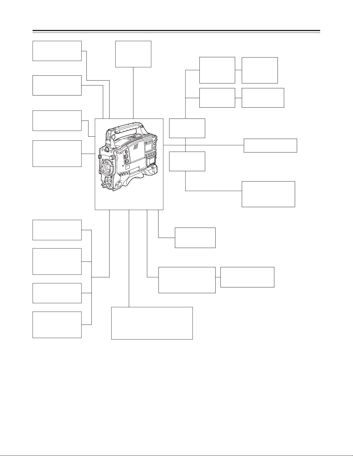
System configuration
Microphone kit
AJ-MC700P
Wireless
microphone
receiver
WX-RJ700
Microphone holder
AJ-MH700P
Lens
(Bayonet type)
FUJINON/CANON
Rain cover
SHAN-RC700
Soft carrying case
AJ-SC900
Tripod mount
adapter
SHAN-TM700
Extension control
unit
AJ-EC3
Camera/VTR
AJ-HDC27F
Setup memory card
Multi-media card:
VW-MMC8
SD (Secure Digital) memory card:
RP-SD008B
Battery case
AU-M402H
AC adapter
AJ-B75
Cassette tape
AJ-HP23LP
AJ-HP32LP
AJ-HP46LP
Cleaning tape
AJ-CL12LP
BP-90 type
battery
Sony
Battery case
NP/BP
adapter plate
V-mount
adapter plate
Sony Battery
BP-90
NP-1
Anton/Bauer Battery
IDX Battery
E-50, E-80
Sony Battery
BP-L60/L90
2.0-inch viewfinder
AJ-HVF27P
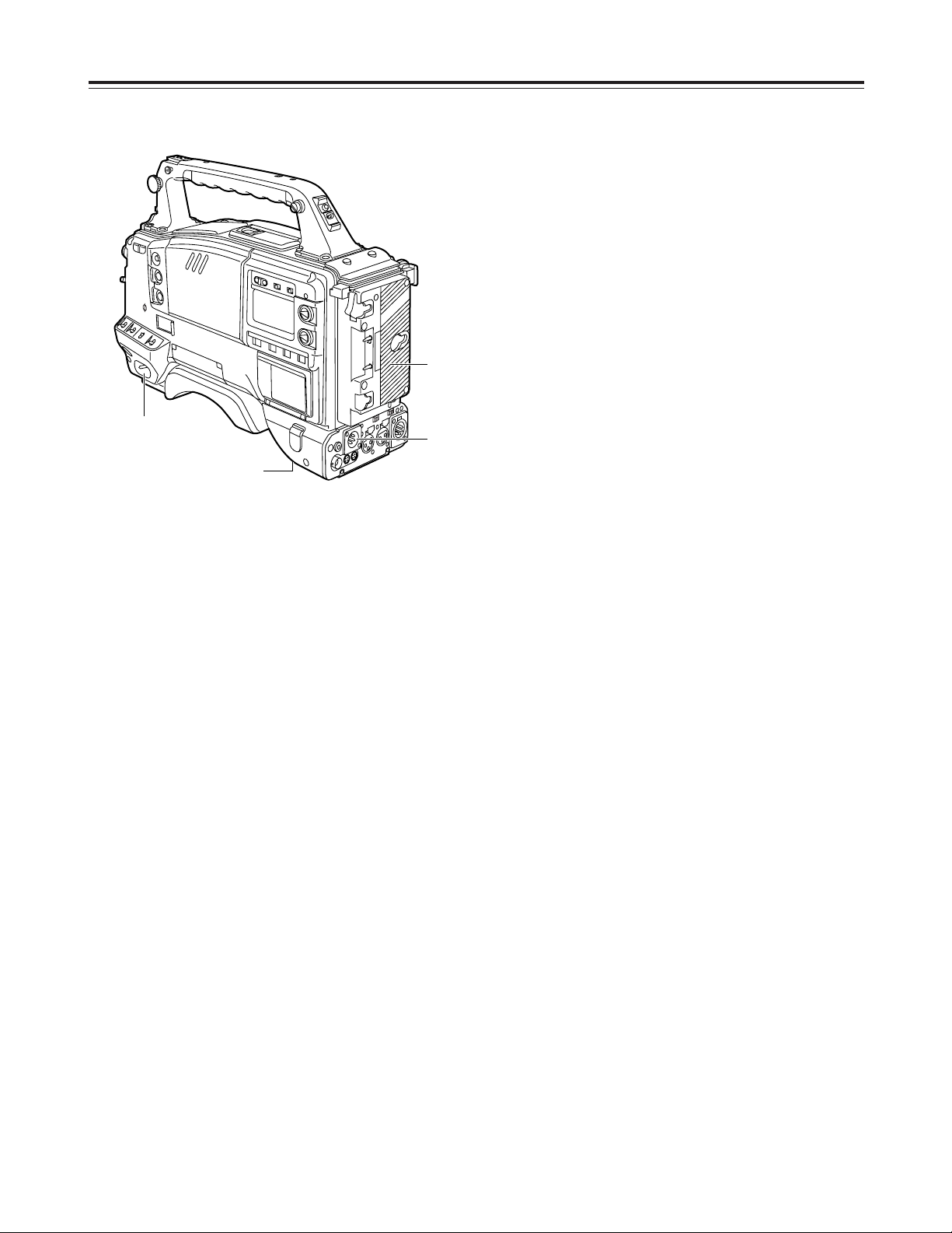
9
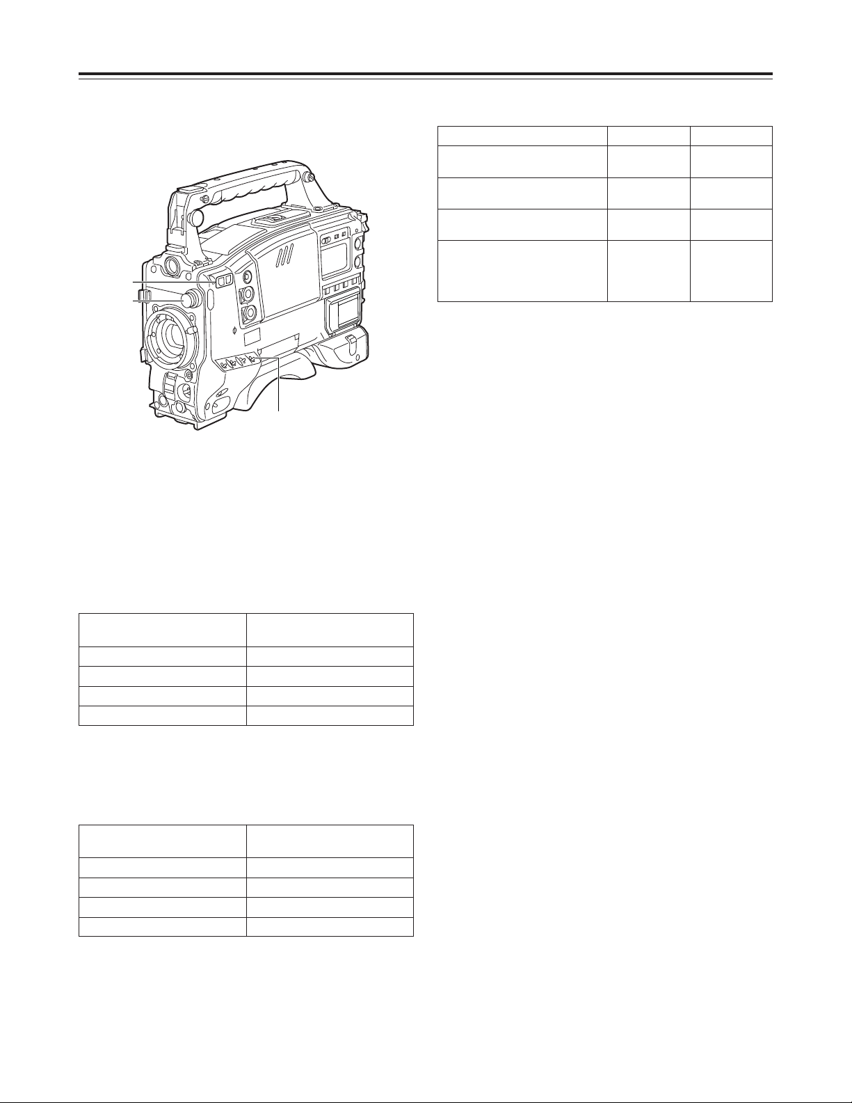
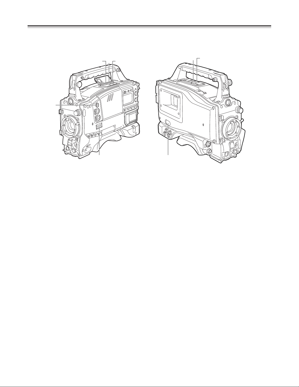
Power supply section
1 Battery mount
This is for attaching the Anton/Bauer battery pack.
2 DC IN (external power input) socket (XLR, 4P)
When operating this unit using an AC power
source, this socket is connected to the model AJB75 AC adapter (optional accessory).
3 BREAKER button
To protect the equipment, the circuit breaker is
tripped when an overcurrent flows inside the unit,
and the power is automatically turned off. Push this
button to the pushed-in position after performing
internal inspections and adjustments. If there is no
problem, the power will be turned back on.
4 POWER switch
ON
: Set here to turn on the power.
OFF
: Set here to turn off the power.
Parts and their functions
4
1
2
3
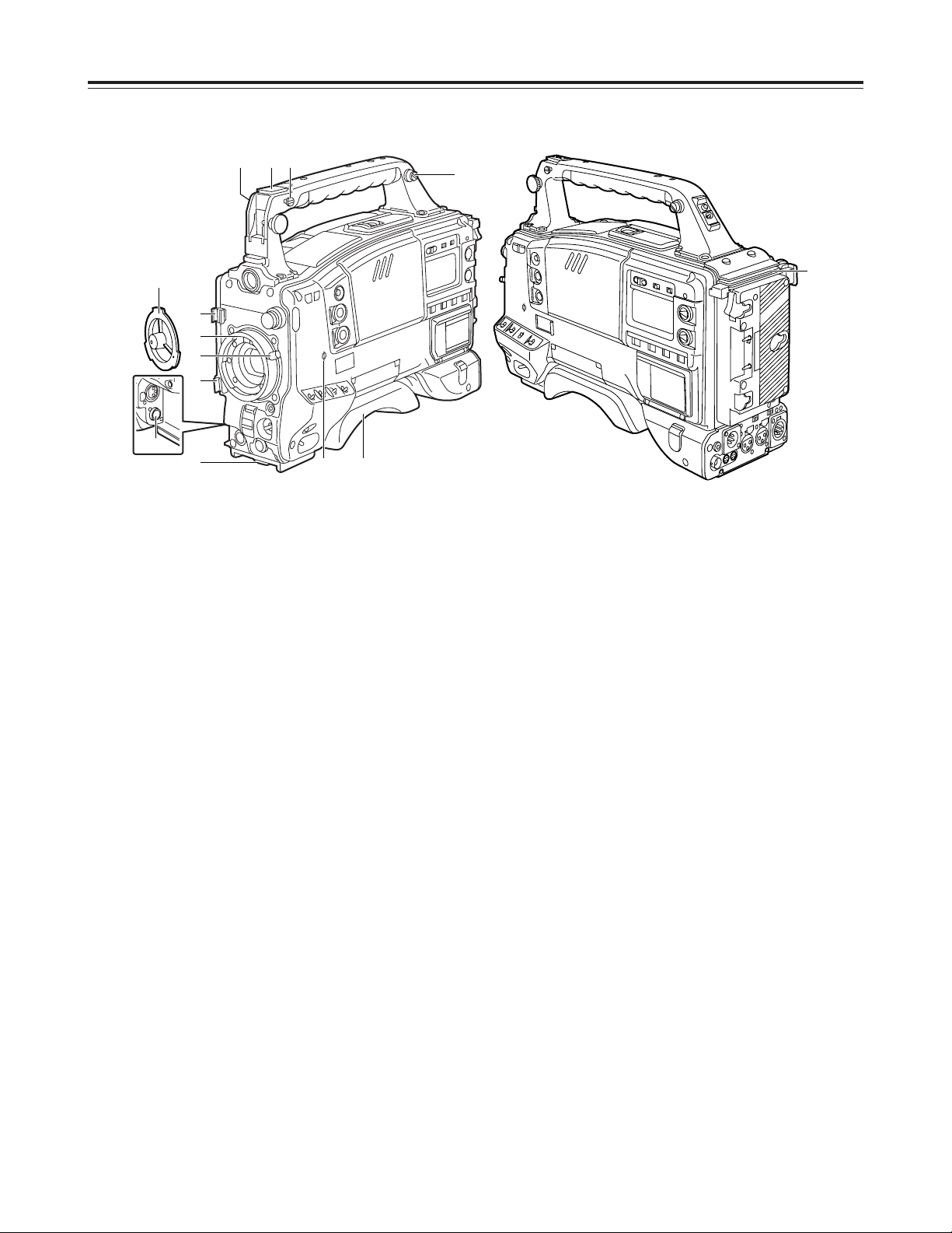
9 Shoulder pad
This pad can be adjusted to facilitate operation
when the unit is operated on the user’s shoulder.
The pad position can be moved forward or
backward when the two securing screws are
loosened.
: Mounting hook for tape measure
The tape measure used to measure the subject
distance is attached here.
<Note>
This hook is not to be used for the shoulder strap.
; Focus mark
This indicates the focus position of the CCD unit.
< Spacer to support extension unit
Future plans call for this connector to be used to
support some options.
10
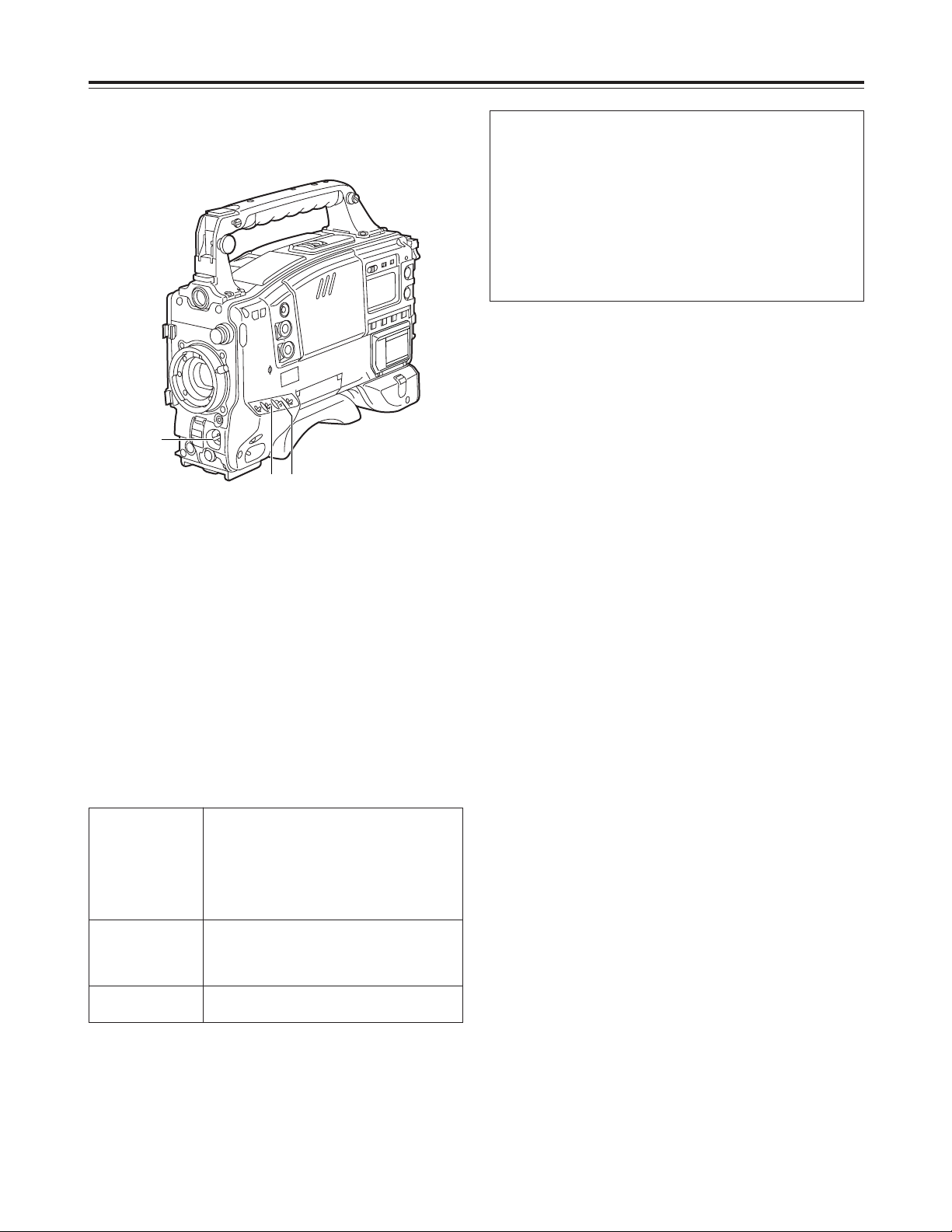
Parts and their functions
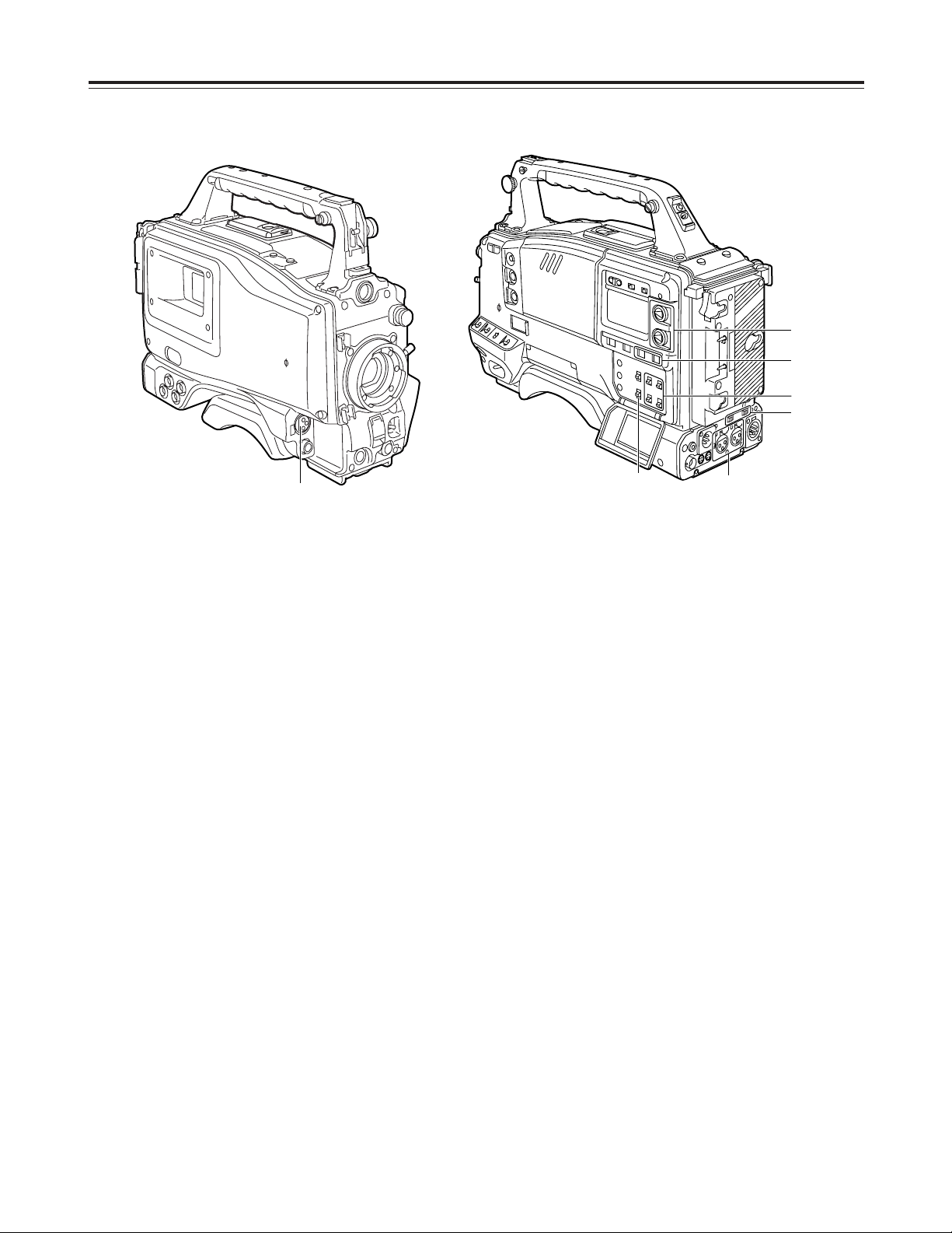
Accessory mounting section
1 Hooks for attaching shoulder strap
Attach the ends of the accessory shoulder strap to
these hooks.
2 Light shoe
Use this to attach the video light, etc.
3 Lens mount (Bayonet type)
Use this to attach the lens.
4 Lever for securing lens
Insert the lens into the lens mount 3, and turn the
lens mount ring using this lever to secure the lens.
5 Lens mount cap
To remove the cap, push the lever for securing the
lens 4 up.
Keep the cap in place while the lens is not
attached.
6 Lens cable/microphone cable clamp
This clamp is for anchoring the lens cable or
microphone cable.
7 Tripod mount
Mount the tripod attachment (SHAN-TM700),
available as an optional accessory, when the unit is
to be anchored to the tripod.
8 LENS terminal (12-pin)
The connecting cable of the lens is connected here.
For details concerning the lenses that can be used,
consult your dealer.
1 2 :
1
6
6
3
4
7
5
; 9
<
8
11
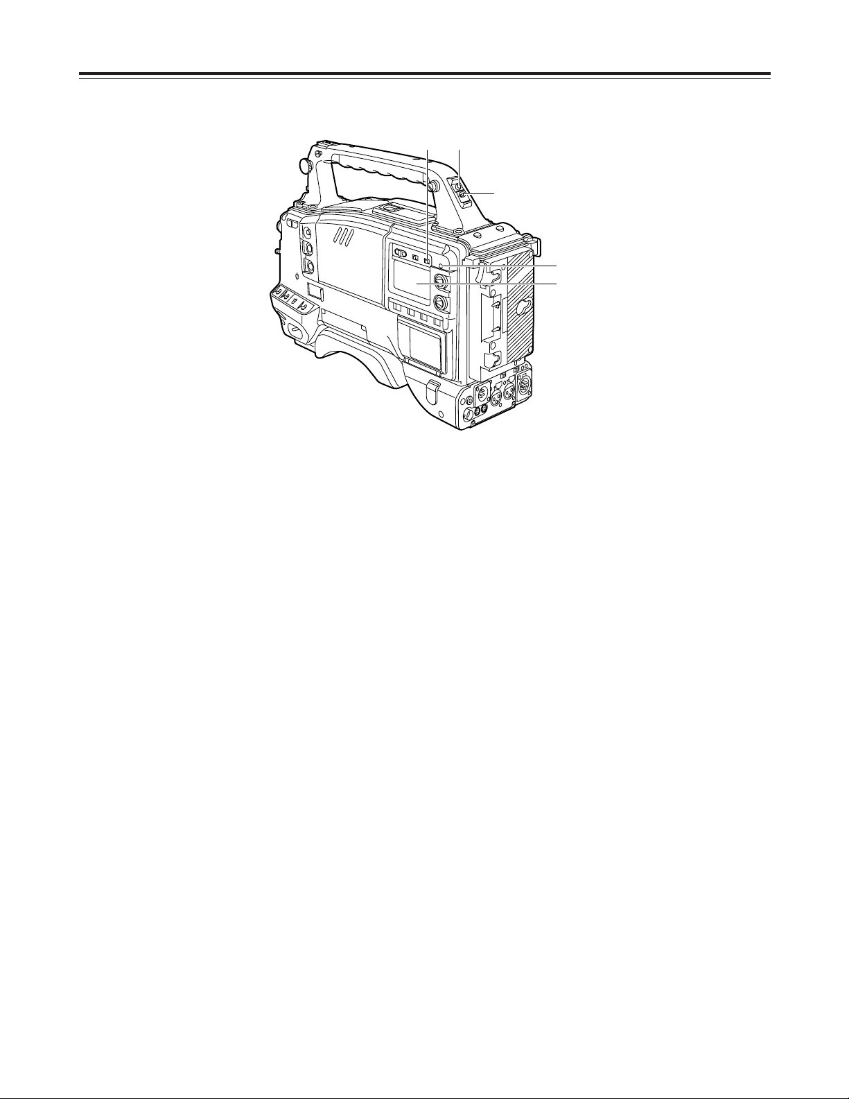
Audio function section (1)
1 MIC IN (microphone input) jack (XLR, 3-pin)
Connect the microphone (optional accessory) here.
The power for the microphone is supplied from this
jack.
2 AUDIO LEVEL CH1/CH2 (audio channel 1 & 2
recording level adjustment) controls
When the AUDIO SELECT CH1/CH2 switch 3 is
set to MAN, the recording level of audio channels 1
and 2 can be adjusted using these controls.
3 AUDIO SELECT CH1/CH2 (audio channel 1 & 2
automatic/manual level adjustment selector)
switch
This is used to select the method for adjusting the
audio levels of audio channels 1 and 2.
AUTO
: Set here for automatic adjustment.
MAN
: Set here for manual adjustment.
4 AUDIO IN (audio input selector) switch
This is used to select the input signals to be
recorded on audio channels 1 and 2.
FRONT
: The input signals supplied from the
microphone which has been connected to
the MIC IN jack 1 are recorded.
REAR
: The audio input signals supplied from the
audio component which has been
connected to the AUDIO IN CH1/CH2
connectors 5 is recorded.
5 AUDIO IN CH1/CH2 (audio input channel 1 & 2)
connectors (XLR, 3-pin)
An audio component or microphones are connected
here.
6 LINE/MIC/+48V (line input/mic input/mic input +
48V) selector switch
This is used to switch the audio input signals from
the audio component which has been connected to
the AUDIO IN CH1/CH2 connectors 5.
LINE
: The audio input signals from the audio
component serving as the line input are
selected.
MIC
: The audio input signals from the internal
power supply type of microphone are
selected. (The phantom mic power is not
supplied from the unit.)
+48V
: The audio input signals from the external
power supply type of microphone are
selected. (The phantom mic power is
supplied from the unit.)
7 CUE switch
CH1
: The audio CH1 signals are recorded on the
cue track.
MIX
: Audio CH1 and CH2 mixed signals are
recorded on the cue track.
CH2
: The audio CH2 signals are recorded on the
cue track.
<Note>
This switch can be made ineffective using the VTR
MAIN MENU. (See page 116)
Parts and their functions
6
5
7
1
2
3
4
12
Audio function section (2)
8 AUDIO OUT connector (XLR, 5-pin)
This is connected to the audio component.
The sound of audio CH1 and the sound of audio
CH2 are output separately.
The switching of the recording sound and playback
sound is coupled with the setting of the MONITOR
OUT SDI switch. (No sound will be output when
the SDI switch is at OFF.)
9 DC OUT (DC power output) socket
This is the DC 12 V output socket. A current of
approximately 400 mA can be supplied.
: ALARM (warning alarm volume adjustment)
control
This is used to adjust the volume of the warning
alarms from the earphone which has been
connected to the speaker < or PHONES jack ?.
The warning alarms are not audible when this
control is at its lowest setting.
; MONITOR (volume adjustment) control
This is used to adjust the volume of all the sound
delivered through the speaker or earphone except
for the warning alarms.
The sound is not audible when this control is at its
lowest setting.
Parts and their functions
< Speaker
The EE sound during recording or the playback
sound during playback can be monitored through
this speaker.
The warning alarms are output in synchronization
with the flashing or lighting of the warning lamps
and warning displays.
The sound heard from the speaker is automatically
cut off when the earphone is connected to the
PHONES jack ?.
= MONITOR SELECT (audio channel selector)
switch
This is used to select the audio channels whose
sound is to be output from the speaker or
microphone.
CH1
: The audio CH1 signals are output.
1/2 : The audio CH1 and CH2 mixed signals or
stereo audio signals are output. However,
only mixed signals are output through the
speaker.
CH2
: The audio CH2 signals are output.
> MONITOR (audio selector) switch
This is used to select the sound which is to be
output to the earphone when “1/2” has been
selected by the MONITOR SELECT switch =.
ST
: The audio CH1 and CH2 stereo audio signals
are output.
MIX
: The audio CH1 and CH2 mixed audio signals
are output.
? PHONES (earphone) jack (mini jack)
When an earphone (optional accessory) is
connected, the sound selected by the MONITOR
switch > can be heard from the earphone. In
addition, the warning alarms relating to the unit’s
operations or statuses can be heard through the
earphone. An earphone which is capable of
delivering a sufficiently high volume is
recommended. However, when the earphone is
connected, the sound heard through the speaker <
will be automatically cut off.
<
=>
8
:
;
9?
13
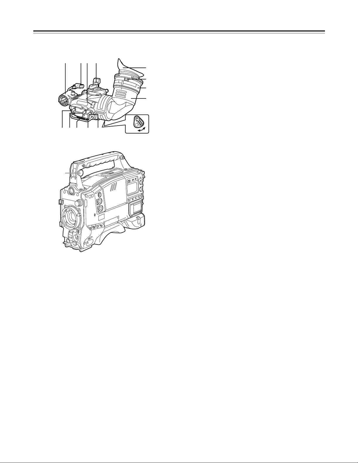
Viewfinder section
(Viewfinder pictured here is the AJ-HVF27P)
(For details concerning the viewfinder, refer to the
operating intructions of the viewfinder.)
Parts and their functions
ON
OFF
2
:
87<>
=
1
;
9
3645
3 TALLY switch
This is used to control the front tally lamp 7.
HIGH
: The brightness of the front tally lamp is
increased.
OFF
: The front tally lamp is turned off.
LOW
: The brightness of the front tally lamp is
reduced.
4 PEAKING control
This is used to adjust the outlines of the images
seen inside the viewfinder to make focusing easier.
Its adjustment does not affect the output signals of
the camera.
5 CONTRAST control
This is used to adjust the contrast of the picture
seen inside the viewfinder. Its adjustment does not
affect the output signals of the camera.
6 BRIGHT control
This is used to adjust the brightness of the picture
seen inside the viewfinder. Its adjustment does not
affect the output signals of the camera.
7 Front tally lamp
This lamp is activated when the TALLY switch 3 is
set to the HIGH or LOW position, and it lights while
the VTR unit is recording. It also flashes to provide
a warning display like the REC lamp inside the
viewfinder. The lamp’s brightness when it is lighted
can be selected using the TALLY switch (HIGH or
LOW).
8 Lever for securing the viewfinder in the
back/front and sideways directions
This lever is loosened when the viewfinder position
is to be adjusted in the back/front and/or sideways
directions.
9 Eyepiece
: Back tally lamp
This lamp lights while the VTR unit is recording. It
also flashes to provide a warning display like the
REC lamp inside the viewfinder.
When the lever is set to OFF, the back tally lamp is
hidden.
; Diopter adjustment ring
This is adjusted in line with the camera operator’s
diopter in such a way that the user can see the
image on the viewfinder screen most clearly.
< Connecting plug
= Locking ring
> Microphone holder
? Viewfinder stopper screw
To detach the viewfinder from the camera, first
loosen the stopper screw, and then remove the
viewfinder.
1 Viewfinder (optional accessory)
While recording or playback is underway, pictures
can be viewed through the viewfinder in black and
white. The warning displays concerning the unit’s
operation statuses and settings, messages, zebra
patterns and markers (safety zone markers and
center marker) can also be seen in the viewfinder.
2 ZEBRA (zebra pattern) switch
This is used to display the zebra pattern in the
viewfinder.
ON
: The zebra pattern is displayed.
OFF
: The zebra pattern is not displayed.
When the unit is shipped, the zebra pattern is set
so that an area of less than 85% is displayed with a
video level of at least 80% or so.
The required area of zebra pattern can be
displayed by setting the ZEBRA 1 DETECT,
ZEBRA 2 DETECT and ZEBRA 2 items on the
FILM (CAM) MAIN MENU 2 screen.
?
14
2 Synchro scan adjustment switches
These switches become effective when the shutter
switch 7 is set to ON and SYNCHRO SCAN 2 is
selected. They are used to adjust the synchro scan
speed.
When the “–” switch is pressed, the shutter speed is
reduced; conversely, when the “+” switch is
pressed, it is increased.
During personal computer monitor shooting, etc.
adjust these switches to the positions where the
horizontal bar noise inside the viewfinder is
decreased.
3 WHITE BAL (white balance memory selector)
switch
PRST
: Set the switch to this position in cases where
there is not enough time to adjust the white
balance. The TUNGSTEN (3200 K) white
balance value is stored in the memory.
This can be changed to DAY LIGHT (5600
K).
A or B
: When the AUTO W/B BAL switch 6 is set to
AWB, the white balance is automatically
adjusted to match the setting position of the
CC FILTER control 1, and the adjustment
value is stored in memory A or memory B.
When the CC FILTER control and the WHITE BAL
switch are set to the same positions as they were
when adjustment was performed, the adjustment
value stored in the memory is recalled, and the unit
is automatically adjusted to the white balance that
corresponds to this value.
If this switch setting is changed while the menu
display mode is set to “3” (default setting), the new
setting will appear at the WHITE BAL switch display
position on the viewfinder screen.
(Example: “A”)
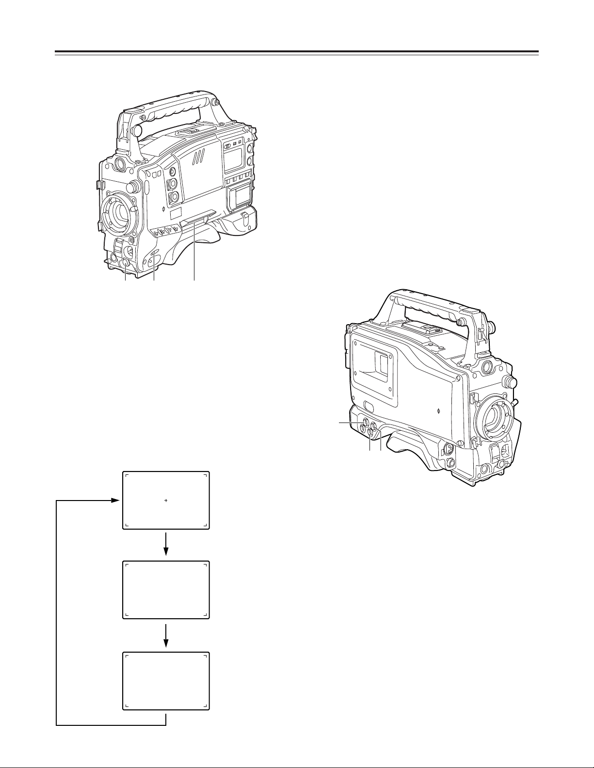
Shooting (recording)/playback
function section (1)
1 CC FILTER/ND FILTER (filter selector) control
This is used to select the filter to match the light
source which is illuminating the subject. If the
control setting is changed while the menu display
mode is set to “3” (default setting), the new setting
will appear at the setting change message display
area of the viewfinder screen.
OThe two types shown above are provided for filter
combinations.
$ Control settings and filter selection
Parts and their functions
$ Examples of filter selection
Shooting conditions
CC filter
Sunrise, sunset, inside a studio
B (3200 K)
ND filter
1 (CLEAR)
Outdoors under a clear sky
C (4300 K) or
D (6300 K)
2 (1/4 ND) or
3 (1/16 ND)
Outdoors under cloudy or rainy
skies
D (6300 K)
1 (CLEAR) or
2 (1/4 ND)
Snowscapes, high mountains,
seashores or other perfectly clear
scenery
C (4300 K) or
D (6300 K)
3 (1/16 ND) or
4 (1/64 ND)
CC FILTER control (large
diameter) setting
CC filter selection
A
Cross filter
B
3200 K
C
4300 K
D
6300 K
ND FILTER control (small
diameter) setting
ND filter selection
1
CLEAR (Transparent)
2
1/4 ND
3
1/16 ND
4
1/64 ND
3
1
2
<Note>
The color temperatures shown above are those when the
LIGHTING item is set to TUNGSTEN or the D5600K item is set to
OFF on the CAMERA SETTING screen of FILM (CAM) MAIN
MENU 1.
15
Shooting (recording)/playback
function section (2)
4 OUTPUT (output signal selector)/AUTO KNEE
switch
This is used to select the video signals which are to
be output from the camera unit to the VTR unit,
viewfinder and video monitor.
The AUTO KNEE function can be used when the
pictures shot by the camera are selected.
The operation of the AUTO KNEE function can be
selected using the AUTO KNEE SW item on the
CAMERA SW MODE screen of FILM (CAM) MAIN
MENU 2.
(The factory setting of the AUTO KNEE function is
OFF.)
5 GAIN (gain selector) switch
This is used to select the gain of the video amplifier
in accordance with the lighting status during
shooting. The gain values corresponding to the L,
M and H settings are specified by the setting menu
ahead of time.
If this switch setting is changed while the display
mode is set to “3,” the new setting will appear at the
gain display position on the viewfinder screen.
(Example: “12 dB”)
6 AUTO W/B BAL (automatic white balance/black
balance adjustment) switch
AWB
: This is selected when the white balance is to
be adjusted automatically. When the WHITE
BAL switch 3 is set to “A or B” at this time,
the adjusted value will be stored in memory A
or memory B.
ABB
: This is selected for automatically adjusting the
black balance.
The adjusted value is stored in a dedicated
memory.
Black shading is automatically corrected when
SHD and ABB SW CTRL on the OPTION
screen of FILM (CAM) MAIN MENU 4 are set
to ON and the AUTO W/B BAL switch is
pressed continuously for 8 seconds or more
on the ABB side.
Parts and their functions
$ OUTPUT/AUTO KNEE switch setting position
BARS
Color bar signals are output.
The AUTO KNEE circuit is not activated.
Use this position in the following
circumstances.
OWhen the video monitor is to be adjusted
OWhen the color bar signals are to be
recorded
CAM.
AUTO KNEE OFF
The pictures shot by the camera are output.
The AUTO KNEE circuit is not activated.
MANUAL KNEE is selected as the default
setting.
CAM.
AUTO KNEE ON
The pictures shot by the camera are output.
The AUTO KNEE circuit is activated.
AUTO KNEE function
If the level is adjusted to people or scenery for shooting when the
background is very bright, the background becomes subject to
white-out, causing the buildings and scenery in the background to
be blurred. When the AUTO KNEE function is activated in a
situation like this, the background can be reproduced distinctly.
This function is very effective for shooting in the following
situations.
OWhen shooting people in the shade under a clear sky
OWhen shooting people inside a vehicle or a building and
outdoor scenery seen through windows at the same time
OWhen shooting scenes with a high contrast
<Note>
When white balance or black balance are being
automatically adjusted and the switch is pressed
again to either the AWB side or to the ABB side, the
automatic adjustment for the side pressed will be
stopped.
The adjusted value in this case is the value before
automatic adjustment was performed.
6
5 4
16
Shooting (recording)/playback
function section (3)
7 SHUTTER switch
This is set to ON when the electronic shutter is to
be used. When the SEL side is pressed, the
shutter speed and mode display are changed in the
range which was set ahead of time in the setting
menu.
If this switch setting is changed while the display
mode is set to “2” or “3,” the new setting will appear
at the shutter display position on the viewfinder
screen.
(Example: “: 1/120”, “: 50%”, “: 180d”)
8 ECU REMOTE (remote control) connector (6-
pin)
The AJ-EC3 extension control unit (optional
accessory) is connected here.
<Note>
Before connecting or disconnecting the remote
control cable, be absolutely sure to set the POWER
switches on the unit and extension control unit to
the OFF position.
9 HD SDI OUT connector (BNC)
The HD SDI signals (video and audio) for the
monitor in accord with the position of the MONITOR
OUT SDI switch : are output from here.
When the SDI switch is at “EE/PB,” the EE video
and EE audio signals will be output during
recording and the playback video and playback
audio signals will be output during playback.
When the SDI switch is at “EE,” the camera video
signals are output at all times.
When the CHARACTER switch is set to ON while
performing the menu settings, it is possible to
superimpose the setting menus onto the pictures
being shot so that they can be checked on the
monitor screen.
The user’s bit is also output from the HD SDI OUT
connector.
The active frame count is output to the four higher
digits of the user’s bit. The count is reset to zero
each time recording starts, and the count is
incremented with each active frame.
The active frame information is output to the lowest
digit of the user’s bit while the frame rate
information is output to the third and fourth lower
digits.
<Note>
In order for the time code that matches the
playback time code, which is output from the HD
SDI OUT connector, to be output from the TC OUT
connector, set the SDI switch to “EE/PB,” and
select “TCG/TCR” as the TC OUT item setting on
the TC/UB screen.
Parts and their functions
9
79
8
17
Shooting (recording)/playback
function section (4)
: SDI switch
This is used to select the video and audio signals
which are to be output from the HD SDI OUT
connector and the audio signals which are to be
output from the AUDIO OUT connectors.
EE/PB
: During playback, the playback video and
playback audio signals are output; in all
other modes, the EE video and EE audio
signals are output.
EE
: The EE video and EE audio signals are
output at all times.
OFF
: Signal output is stopped. (This serves
effectively as a power-conserving mode.)
<Notes>
O With the settings at shipment, this function does
not work at the OFF position when a cable is
connected to the HD SDI OUT connector. For
further details, refer to the FUNCTION screen
(page 112) of the VTR menu.
During recording, the HD SDI OUT output
signals cannot be switched from ON to OFF or
vice versa. The status set prior to the
commencement of recording is maintained.
O When the frame frequency has been set to 60.00
Hz, the audio signals which are output from the
HD SDI OUT connector can be controlled on the
MIC AUDIO screen of VTR MENU.
However, it should be borne in mind that some
products may not be able to process properly the
audio signals which are output from the HD SDI
OUT connector at this 60.00 Hz frequency
setting.
For details, consult your dealer.
; CHARACTER switch
This controls whether the characters are to be
superimposed onto the pictures which are output
from the HD SDI OUT connector.
ON
: The characters are superimposed.
OFF
: The characters are not superimposed.
< VTR START button
When this is pressed, recording starts; when it is
pressed again, recording stops.
This button functions in the same way as the lens
VTR button.
= VTR SAVE/STBY (tape protection) switch
This is used to select the power supply mode when
the VTR has temporarily stopped recording (REC
PAUSE mode).
SAVE
: This is the tape protection mode. The
cylinder is stopped in the half-loading status.
Less power is consumed than at the STBY
position, and the operating time provided by
the battery is prolonged. Compared with the
STBY position, it takes longer for recording to
commence after the VTR START button <
has been pressed.
When the switch is set to this position, the
VTR SAVE lamp inside the viewfinder lights.
STBY
: At this position, recording is commenced as
soon as the VTR START button is pressed.
<Note>
When the prescribed amount of time has elapsed in
the STBY mode, the unit is automatically set to the
SAVE mode. To return the unit to the STBY mode,
set the VTR SAVE/STBY switch to SAVE, and then
again to the STBY position.
Parts and their functions
= ;
<
:
18
Shooting (recording)/playback
function section (5)
C PLAY/PAUSE button
This is pressed to view the playback picture on the
viewfinder screen or using a color video monitor.
The button’s lamp comes on during playback.
When it is pressed during playback, the unit is set
to pause in the playback mode (PLAY PAUSE), and
the button’s lamp flashes. If the unit is left in the
pause mode for two minutes, it automatically
changes to the stop (STOP) mode.
D STOP button
This is pressed to stop the tape travel.
E EMERGENCY screw (inside rubber cap)
If the cassette does not eject even when the EJECT
button is pressed, use a screwdriver or similar
implement to push and turn the EMERGENCY
screw at the same time: this will cause the cassette
to be ejected.
Parts and their functions
> MODE CHECK button
While this button is held down, the camera’s setting
mode is shown in the viewfinder.
This does not affect the output signals of the
camera.
? USER 1 and USER 2 buttons
A user setting can be allocated to each of these
buttons using the setting menu.
When a button is pressed, the user setting mode
allocated to it is selected.
When the button is pressed again, the selected
mode is released.
@ EJECT button
This is pressed to insert or eject the cassette.
A REW button
This is pressed to rewind the tape. The button’s
lamp comes on during rewinding.
When it is pressed during playback, the tape will be
reviewed (rewound and played back) at about twice
the regular speed while the button is held down.
B FF button
This is pressed to fast forward the tape. The
button’s lamp comes on during fast forwarding.
When it is pressed during playback, the tape will be
cued (fast forwarded and played back) at about
twice the regular speed while the button is held
down.
C
D
A
? E
B
@
>
19
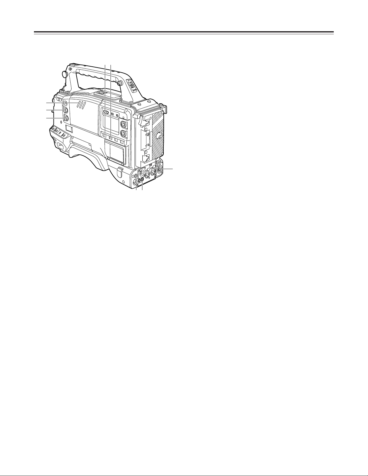
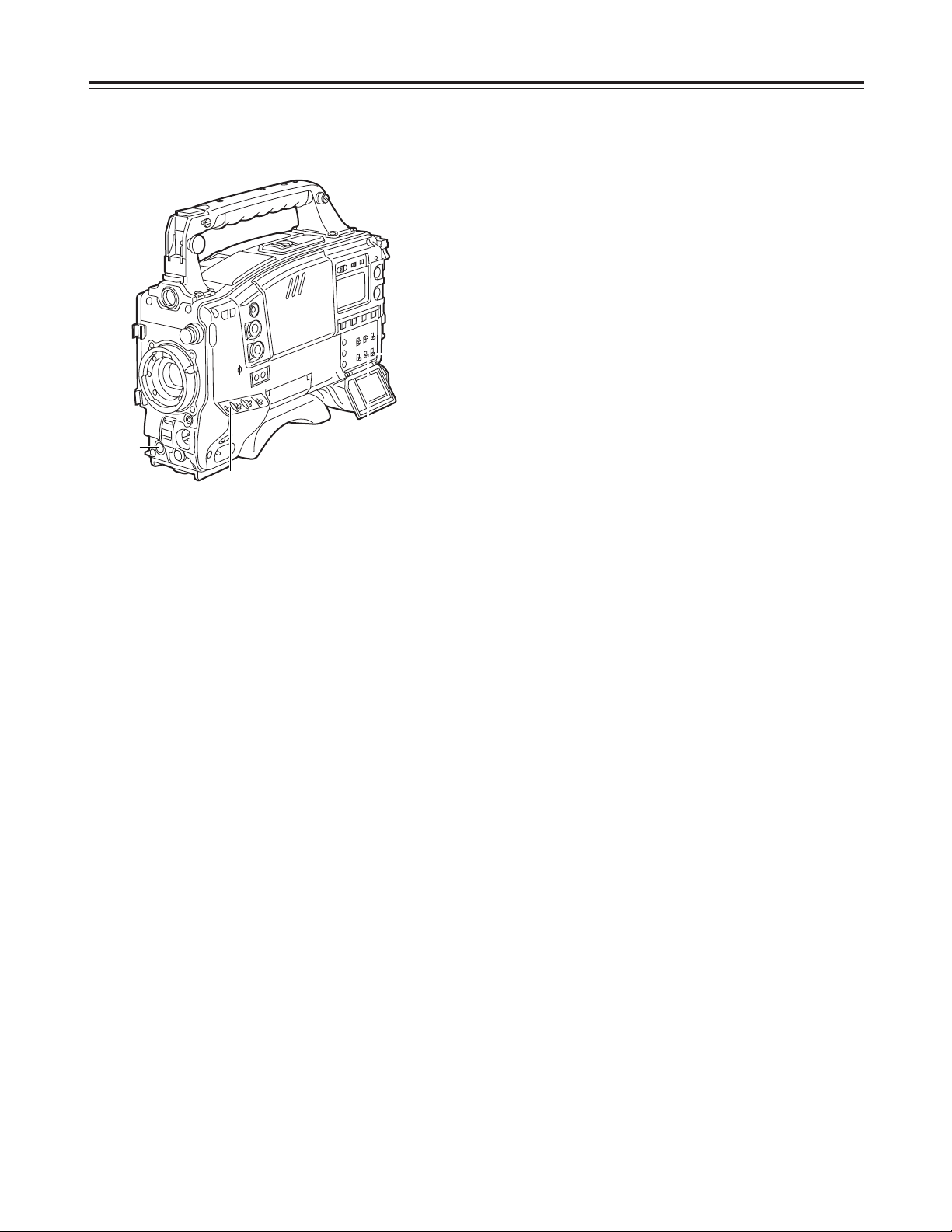
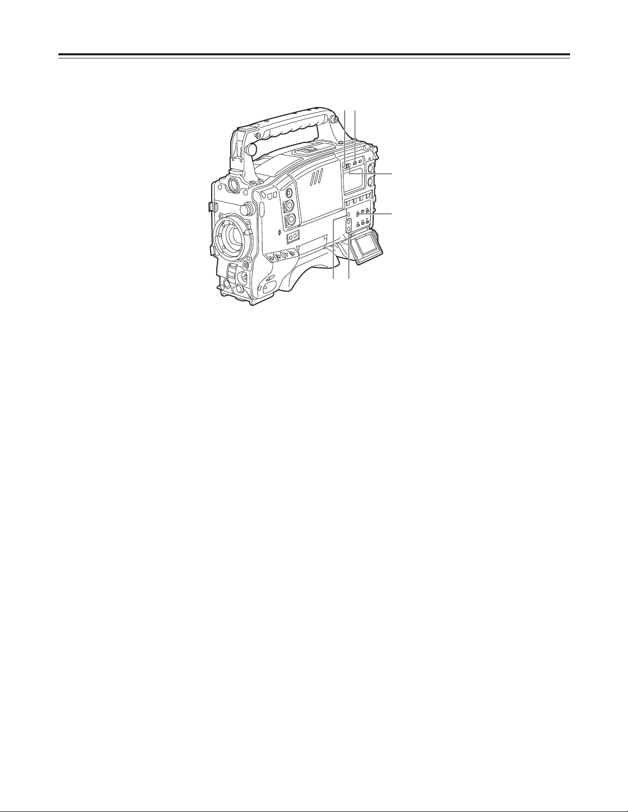
Warning/status display section
1 Back tally lamp (unit)
When the back tally switch 2 is set to ON, this
lamp serves the same function as the front tally
lamp in the viewfinder.
2 Back tally switch
This is used to control the unit’s back tally lamp 1.
ON
: The unit’s back tally lamp is operational.
OFF
: The unit’s back tally lamp is not operational.
3 WARNING lamp
When a problem of some form or other occurs
within the VTR unit, this lamp flashes or lights.
4 LIGHT switch
ON
: The display window 5 is illuminated.
OFF
: The illumination of the display window is
turned off.
5 Display window
This displays the alarms, remaining battery charge,
audio levels, time data, etc. relating to the VTR unit.
Parts and their functions
3
5
14
2
20
1AB 0dBCZ73
¢¢¢¢ VTR USER MENU ¢¢¢¢
¢¢¢¢ FILM USER MENU ¢¢¢¢
Menu operation section
1 Setup card insertion slot
The setup card, available as an optional accessory,
is inserted into this slot.
2 MENU button
When this is pressed, the camera unit’s user menu
screen, which was set at the time of shipment,
appears.
When it is pressed again, the VTR unit’s user menu
screen appears.
When it is pressed once more, the menu screen
display is cleared.
The selection of the menu for the user menu can be
changed on the USER MENU SELECT screen.
3 JOG dial button
When this dial button is turned while the menu
screen is displayed, the cursor is moved to each of
the setting items.
The menu items are set by operating this dial
button.
There are two types of menus, MAIN and SUB, and
each menu is displayed on a page-by-page basis.
The menu configuration can be changed to suit the
desired objective.
For details on the menu operation method, refer to
“Menu operations” on pages 84 to 86.
Parts and their functions
When the power is turned on
Status display
Camera unit’s user
menu
VTR unit’s user
menu
Press the MENU
button.
Press the MENU
button.
Press the MENU button.
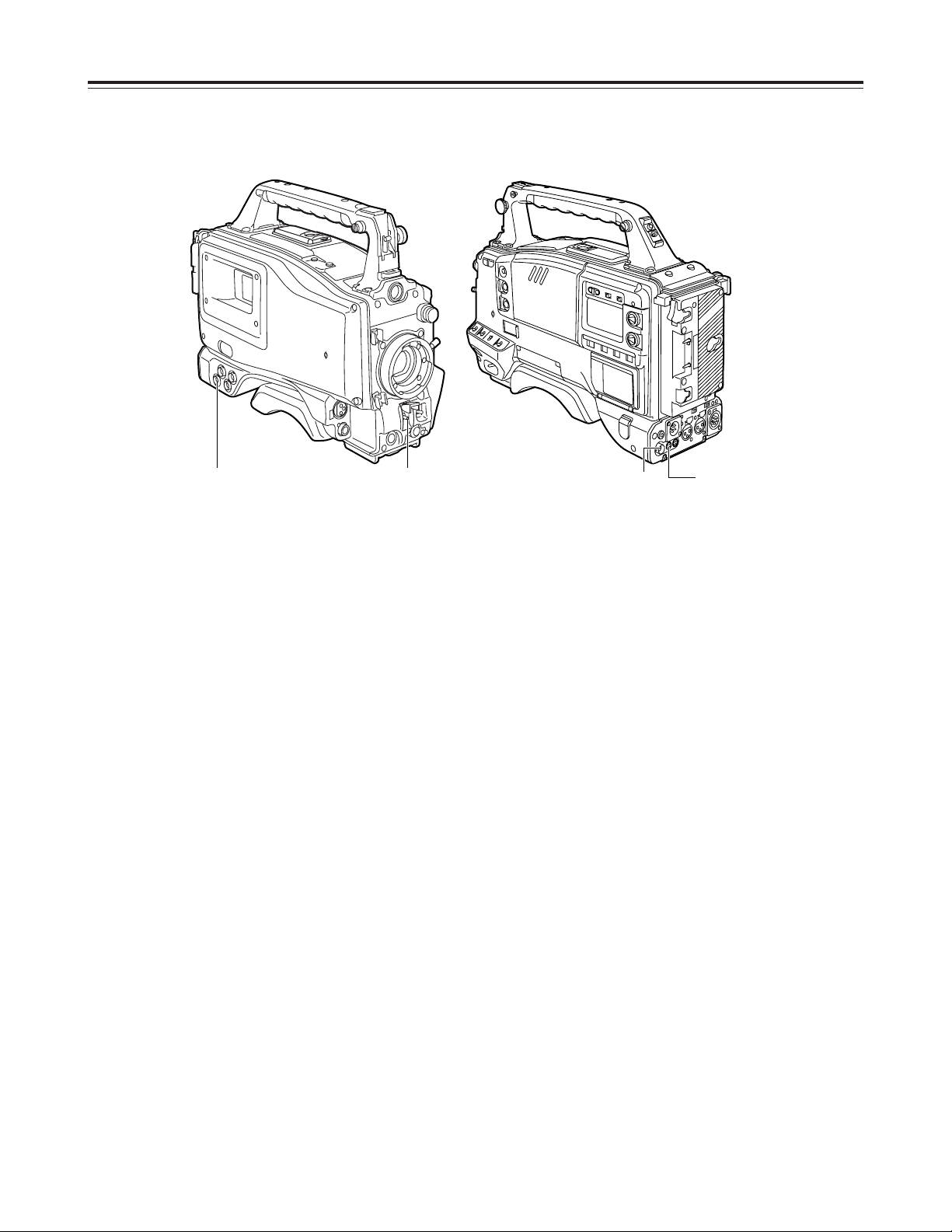
Time code related section (1)
1 GENLOCK IN connector (BNC)
Supply the analog HD reference signal to this
connector for gen-locking the camera unit or when
externally locking the time code.
<Note>
Enter the reference signal of the same frame
frequency (59.94 Hz or 60.0 Hz) as the unit.
2 TC IN connector (BNC)
Supply the time code which will serve as the
reference to this connector when externally locking
the time code.
3 TC OUT connector (BNC)
To lock the time code of an external VTR to the
unit’s time code, connect this connector to the time
code input (TC IN) connector on the external VTR.
3 2 1
3 2
1
21
7 “+” button, “–” button
These are used to increment or decrement by 1 the
figure in the digit which was made to flash by the
SHIFT button 8 when the time code or user’s bit is
to be set.
8 SHIFT button
This causes the digit to be set to flash when the
time code or user’s bit is to be set.
9 TCG (time code selector) switch
This is used to set the running mode of the built-in
time code generator.
F-RUN
: Set here to have the time code run all the
time regardless of the VTR’s operation.
This position is used to align the time code
with the time or externally lock the time
code.
SET
: Set here when the time code or user’s bit is
to be set.
R-RUN
: Set here to have the time code run only
during recording.
The time code on the tape with scene-toscene continuity is recorded continuously.
Time code related section (2)
4 HOLD button
The time data display of the counter display section
which was on the screen at the moment when this
button is pressed is held. (However, the time code
generator keeps running.) When the button is
pressed again, the hold status is released.
It is used, for instance, to find out the time at which
a particular scene was shot.
<Note>
If the HOLD button is pressed and held down while
the DISPLAY switch 6 has been set to UB,
“HOLD” on the counter display flashes, and the
button functions to display the VITC user’s bit
information recorded in the video AUX area on the
counter display section.
5 RESET button
This is used to reset the time data on the counter
display section to “00:00:00:00.” If it is pressed
while the TCG switch 9 is at the SET position, the
time code data and user’s bit data are respectively
reset to “00:00:00:00.”
6 DISPLAY switch
This is used to display the time code, CTL or user’s
bit on the counter display section depending on the
setting positions of this switch and the TCG switch
9.
UB
: The user’s bit is displayed.
TC
: The time code is displayed.
CTL
: CTL is displayed.
Parts and their functions
46
78
9
5
Removal lever
Battery pack
22
Power supply
Using the Anton/Bauer battery pack
A battery pack or an AC power source can be used as
this unit’s power supply.
To use the battery pack, there is a choice of
makes of batteries below, namely:
OAnton/Bauer
OIDX
OSony
<Note>
Batteries of other makes can also be supported by
changing the setting menu but no guarantees are
made for the system when they are actually used with
this unit.
Before using the battery pack, recharge the battery
using the battery charger.
(For details on the recharging method, refer to the
operating instructions of the battery concerned.)
<Note>
An intelligent battery system and ultra light system are
supported.
The remaining battery charge displayed inside the
viewfinder is usually shown as a percentage of the full
charge, but when the battery charge is nearly
completely dissipated, the percentage display is
replaced with a voltage display.
1
Attach the battery pack.
Insert the pack in the direction shown by the
arrows, and then slide it into position.
2
To detach the battery, pull the battery mount
removal lever all the way down, and slide the
battery pack in the direction shown by the arrow.
23
Power supply
Using the BP-90 type battery pack
<Notes>
O Do not pull the rubber cap forcefully.
O When mounting the battery case, take care not to
pinch the connecting cord.
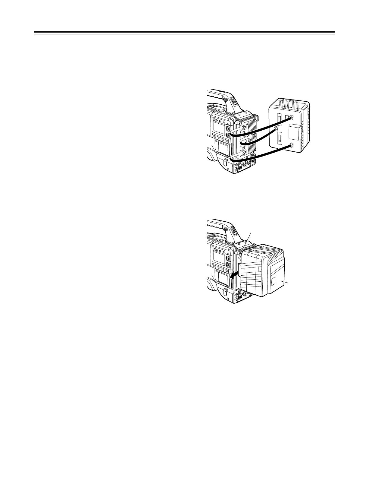
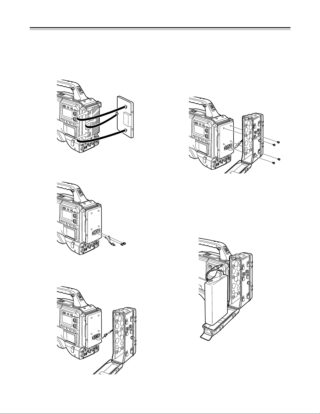
4
Attach the AU-M402H battery case.
Open the battery case cover, and raise it above the
rubber cap: screw holes will now be visible.
Tighten the screws using a screwdriver, then
attach the case to the NP/BP adapter plate and
tighten the screws fully.
5
Connect the plug on the battery pack to the
connector inside the case, and insert the battery
pack.
<Note>
Before connecting or disconnecting the plug, be
absolutely sure to turn off the unit’s power.
3
Connect these connectors with the connector on
the AU-MA402H battery case.
1
Attach the NP/BP adapter plate.
Insert it in the direction shown by the arrows, and
slide it into place.
2
Attach the connectors provided with the NP/BP
adapter plate to the positions shown in the figure.
24
Power supply
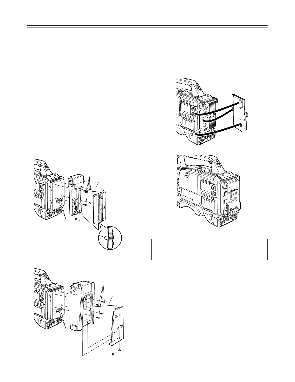
Using the Sony NP-1/BP-90 battery
pack
Attach the Sony battery holder. As shown in the
figure, attach the battery case with the cover detached
and then the detached cover.
1 Tighten the mounting screws.
2 Tighten the power contact screws.
3 Insert the top of the detached cover in the direction
shown by the arrows.
4 Align the holes in the bottom of the cover (metal
part) with the holes at the bottom of the case, and
use the screws to attach the case.
<Note>
When mounting the battery holder, take care not to
pinch the connecting cord.
Using the V-mount type battery
pack
1
3
4
2
Battery case for NP-1
Battery case for BP-90
2
1
3
4
Attach the V-mount adapter plate.
Insert it in the direction shown by the arrows, and slide
it into place.
Please consult your local dealer for any questions
regarding the NP/BP adapter plate or V-mount
adapter plate.
25
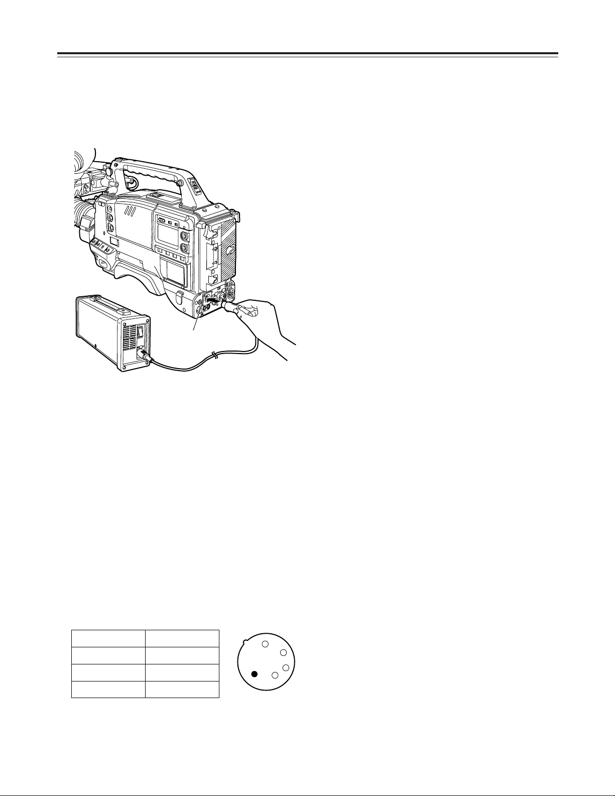
Using an AC power supply
When the AJ-B75 AC adapter is used
<Notes>
O Check the pin signals of the DC IN socket when
using an external power supply other than the AJB75 AC adapter. (DC 12 V, 8.5 A)
O Power from the AC adapter takes precedence when
both a battery pack and AC adapter have been
connected.
O When using the AC adapter, be absolutely sure to
first set the power of the AC adapter to ON and
then set the unit’s power switch to ON.
If the power is turned on in the reverse sequence,
the output voltage of the AC adapter will rise
gradually, and the unit may malfunction as a result.
1
2
3
4
1
Connect the DC OUT connector on the AJ-B75 AC
adapter to the DC IN socket on the unit.
2
Set the power of the AC adapter to ON.
3
Set the unit’s power switch to ON.
Pin no. Signal
1 GND
2, 3
==
4 +12 V
Power supply
DC IN socket
26
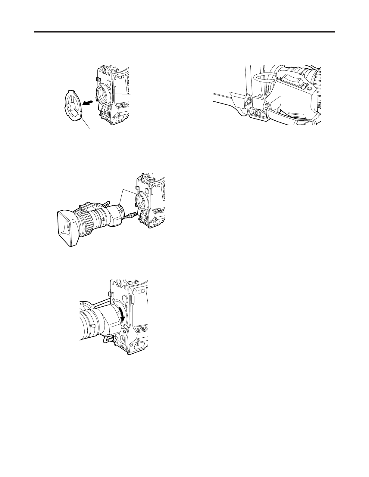
Attaching the lens
1
Raise the lever for securing the lens, and detach
the mount cap.
2
Align the center mark of the lens with the groove in
the top center of the lens mount, and attach the
lens.
3
Push down the lever for securing the lens to
secure the lens.
4
Push the cable into the cable clamp, and connect it
to the LENS socket.
<Notes>
O For details on handling the lens, refer to the
operating instructions which accompany the lens.
O The following lens adjustments and camera
adjustments may be necessary depending on the
lens mounted.
1. Lens flange back adjustment
2. Lens auto iris operating speed adjustment
3. Lens white shading adjustment (performed on
the unit)
Lever for securing
the lens
Mark
LENS socket
Mount cap
27
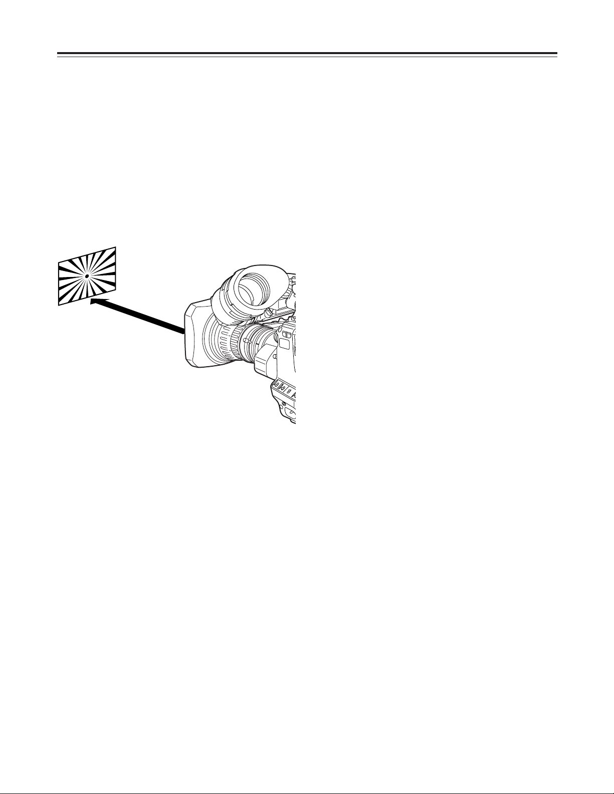
Adjusting the lens flange
If the subject is not focused properly in the telephoto
and wide-angle modes during zoom operations, adjust
the flange back (distance from the lens mounting
surface to the image-forming surface).
Once this adjustment is done, it need not be redone
unless the lens is replaced.
Adjustment method
1
Attach the lens to the camera.
At this stage, do not forget to connect the lens
cable.
2
Set the lens aperture to manual and open the
aperture.
3
Set the lighting in such a way that the appropriate
video output level is achieved at a distance of
about 3 meters away from the chart used for the
flange back adjustment.
If the video level is too high, use the filters and
shutter.
4
Loosen the screw securing the F.f (flange focus)
ring.
<Note>
On some lenses, this may be marked as F.b
(flange back) ring.
5
Set the zoom ring to the telephoto position either
manually or electrically.
6
Shoot the chart used for the flange back
adjustment, and turn the distance ring to adjust the
focus.
7
Set the zoom ring to the wide-angle position, and
turn the F.f ring to adjust the focus.
Take care not to move the distance ring during this
process.
9
Tighten the screw securing the F.f ring.
8
Repeat steps 5 to 7 until the focus is adjusted at
both the telephoto and wide-angle positions.
<Note>
For details on the adjustment method and lens
positions, refer also to the operating instructions that
accompany the lens.
Approx. 3
meters
28
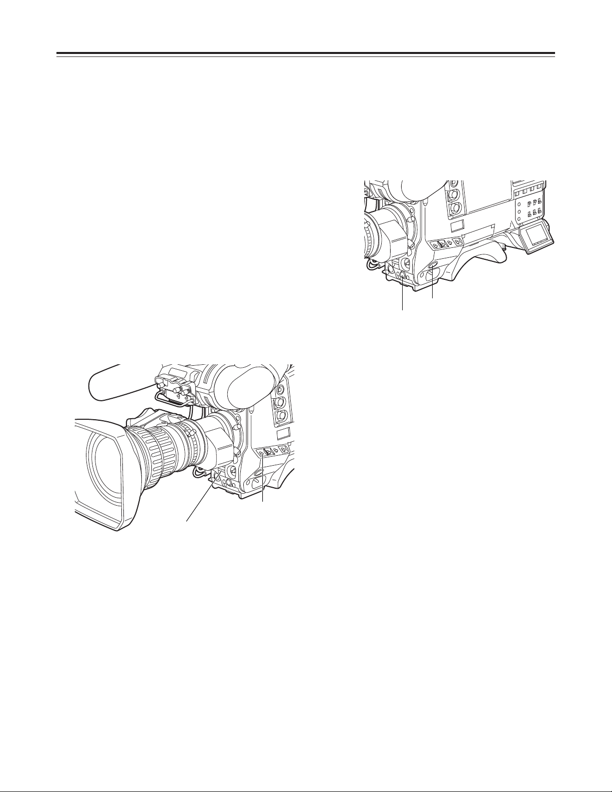
Adjusting the white shading
Follow the procedure outlined below when the white
shading needs to be re-adjusted.
Adjustment method
<Notes>
O The method below can be used for the white
shading adjustments with most lenses. However,
with some very special lenses, a different
adjustment method may be necessary.
O Even when the white shading has been adjusted,
tinting may occur in the vertical direction near the
lens aperture open position. This is a phenomenon
which is inherent to lenses and optical systems and
is not indicative of malfunctioning.
SHUTTER: OFF
GAIN: L (0 dB)
JOG dial button
MENU button
1
Attach the lens to the camera.
At this stage, do not forget to connect the lens
cable.
2
Set the electronic shutter to OFF, and set the gain
to “L (0 dB).”
3
If the lens is provided with an extender, disengage
the extender function.
4
1 Perform the menu operations (pages 84 to 86),
and display the “VF DISPLAY” screen of FILM
(CAM) MAIN MENU 2.
2 Set ZEBRA1 DETECT to 70%, ZEBRA2
DETECT to 85% and ZEBRA2 to SPOT.
3 Press the MENU button and close the menu
screen.
4 Set the ZEBRA switch on the viewfinder to ON.
5
Shoot a sheet of white paper devoid of color
irregularities.
<Note>
Since flicker tends to occur under fluorescent
lights, mercury lamps and other such lights, use a
source of light such as sunlight or a halogen lamp
which does not tend to produce flicker.
6
Set the lens aperture to manual, and adjust the
lens aperture in such a way that ZEBRA fills the
whole screen.
Check that the lens aperture is between F/4 and
F/11.
<Notes>
O Since unevenness in the lighting will make it
impossible for ZEBRA to fill part of the screen,
try adjusting the lighting position, etc.
O Try adjusting the lighting position, etc. also when
the lens aperture is not between F/4 and F/11.
O Always be sure to leave the electronic shutter at
OFF.
29
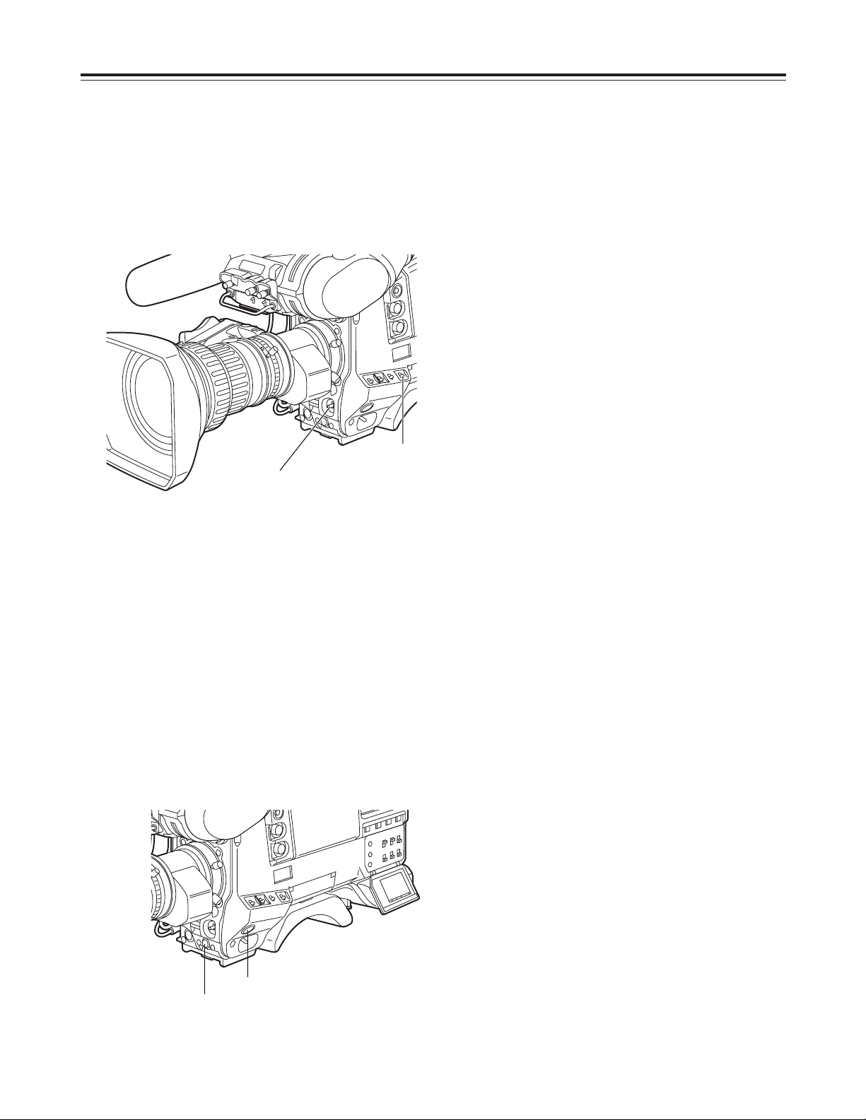
Adjusting the white shading
AUTO W/B BAL
switch
WHITE BAL switch:
“A” or “B”
7
1 Set the WHITE BAL selector switch to “A” or “B,”
and initiate the automatic white balance (AWB)
adjustment using the AUTO W/B BAL switch.
2 Initiate the automatic black balance (ABB)
adjustment using the AUTO W/B BAL switch.
3 Initiate the automatic white balance (AWB)
adjustment again using the AUTO W/B BAL
switch.
9
1 Perform the menu operations (pages 84 to 86),
and display the “WHITE SHADING” screen of
FILM (CAM) MAIN MENU 4.
2 Turn the JOG dial button to move the cursor to
the DETECTION, and press the JOG dial
button.
“ACTIVE” now appears on the screen to indicate
that the white shading is being automatically
adjusted.
The adjustment is completed when the
“ACTIVE” display is cleared.
3 Press the MENU button to close the menu
screen.
8
Repeat step 6.
10
If the lens is provided with an extender, engage
the extender function, and repeat steps 6 to 9.
The white shading adjustment is now complete.
The adjusted values are retained in the non-volatile
memory so that there is no need to adjust the white
shading again even after the unit’s power is turned off.
JOG dial button
MENU button
30
Adjusting the viewfinder (The viewfinder is an optional accessory.)
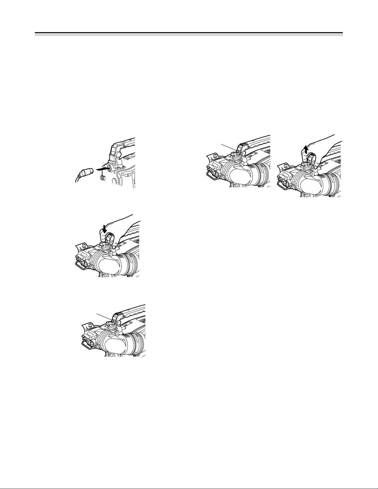
Attaching the viewfinder
1
Check that the camera’s POWER switch is at OFF.
2
Connect the plug to the viewfinder connecting
terminal.
<Note>
When connecting the plug to the viewfinder
connecting terminal, push the plug firmly into
place.
3
Push the viewfinder down.
4
Tighten the stopper screw firmly.
Detaching the viewfinder
1
Check that the camera’s POWER switch is at OFF.
2
Loosen the stopper screw, pull the viewfinder
straight up, and draw it out.
<Note>
Use both hands to draw the viewfinder out. It may
not be possible to remove the viewfinder smoothly
with one hand, which may cause damage to it.
3
Disconnect the plug from the viewfinder connecting
terminal.
Stopper screw
Stopper screw
 Loading...