

Page 1
Model
Name
Model
No.
GA-AS4TPoE+
Product Specification
PN25048-ID
401-25048-ID-SP02
Page 1 of 7
1. Summary
GA-AS4TPoE+ has six ports which are 10BASE-T/100BASE-TX/1000BASE-Tcompatible ports.
Ports 1 to 4 (twisted pair ports) support IEEE802.3at PoE power supply functions.
2. Feature
(1) Ports 1 to 6 (twisted pair ports) are 10BASE-T/100BASE-TX/1000BASE-Tcorresponding to auto-negotiation.
(2) The twisted pair ports 1 to 4 can supply power conforming with IEEE802.3at. They can supply a maximum of 30 W of power per port,
and the device total can supply a maximum of 62 W of power.
(3) All of the twisted pair ports are equipped with straight/cross cable automatic detection functions. Straight cables can be used to make
interconnections without distinctions between the terminals and network devices having to be made.
(The factory default is for ports 1 to 4 to have MDI-X be fixed.)
(4) If equipped with IEEE802.3az (LPI) compatible Energy Efficient Ethernet functions (hereinafter EEE), and if data is transmitted when
linked up, the energy efficient state will be moved to, whereas each port can suppress power consumption.
(5) Automatically detects the connection states via the equipped energy efficiency mode, and suppresses power consumption to required
levels.
(6) VLAN function allows free grouping of up to 256 VLANs.
(7) The IEEE802.1p compatible QoS function is supported.
(8) Has an Internet Mansion function, which ensures security between each door.
(9) The Switching Hub settings can be configured via a web browser. Since the IP address is not set when the Switching Hub is shipped
from the factory, it can be changed by connecting the computer and the Switching Hub which have the ZEQUO assist Plus that is on
the CD-ROM installed on them with the twisted pair cables.
Date issued
Date revised
Nov. 7, 2016
Panasonic Life Solutions Networks Co., Ltd.
Oct. 1, 2020
Page 2
Model
Name
Model
No.
GA-AS4TPoE+
PN25048-ID
3. Rated/Environmental Conditions
3-1. Power supply
3-2. Power consumption
3-3. Operating environment
3-4. Storage environment Temperature: -20 - 70℃
3-5. EMC compliance
3-6. Safety compliance IEC 60950-1
4. Form
4-1. Form and materials/colors
4-2. Mass(Weight) 1,700g
401-25048-ID-SP02
Product Specification
Page 2 of 7
AC100-240V, 50/60Hz, 1.7A (with a built-in power supply)
Normally, Max.77.1W (6.3W when not supplying power), Min.4.3W
Temperature: 0 - 50℃
Humidity: 20 - 80%RH (no condensation)
Humidity: 10 - 90%RH (no condensation)
CISPR 22 Class A, EN 55022 Class A, CISPR 32 Class A, EN 55032 Class A
AS/NZS CISPR22 Class A
VCCI Class A
EN 61000-3-2, EN 61000-3-3
CISPR 24, EN 55024
IEC 61000-4-2, IEC 61000-4-3, IEC 61000-4-4, IEC 61000-4-5,
IEC 61000-4-6, IEC 61000-4-8, IEC 61000-4-11
EN 60950-1
RoHS compliant3-7. Environment compliance
Dimensions :44mm(Height)×210mm(Width)×210mm(Depth)
(Excluding protruding sections)
Case material :SECC
Color : Main unit: Green 03, Front face: Green 03,
Face plate label: Green 02
5. Hardware Specifications
5-1. Interface
Twisted pair port 1-6 :RJ45 connector ※1
Transmitting and receiving network system :
IEEE802.3 10BASE-T
IEEE802.3u 100BASE-TX
IEEE802.3ab 1000BASE-T
Energy Efficient Ethernet :IEEE802.3az (LPI) ※2
Transmission speed :10/100Mbps full/half duplex,
1000Mbps full duplex,
Compatible cable :Twisted pair cable
(At least equivalent to EIA/TIA568 category 5e)
If there is Category 3 cable used in a
connection, the communication at a
speed of 10Mbps can not be established.
You must use category 5e or higher
crossover cable.
Maximum transmission distance :100m
Auto-Negotiation :Communication speed and full/half duplex
are automatically recognized.
The setting can be fixed to 10Mbps, 100Mbps,
1000Mbps and full duplex or half duplex.
Up to 62 W of power can be supplied to ports 1 to 4 in total.
(Maximum power supplied to a port: 30.0W)
※1 Automatically detects the connection states via the equipped Power Saving Mode,
and suppresses power consumption to required levels.
Factory default : Half
Date issued
Date revised
※2 Port 1-4 equipped with IEEE802.3az (LPI) compatible Energy Efficient Ethernet
functions(hereinafter EEE), and if data is transmitted when linked up, the energy
efficient state will be moved to, whereas each port can suppress power consumption.
Factory default : Enable
Nov. 7, 2016
Panasonic Life Solutions Networks Co., Ltd.
Oct. 1, 2020
Page 3
Model
Name
Model
No.
GA-AS4TPoE+
PN25048-ID
5. Hardware Specifications
401-25048-ID-SP02
Product Specification
Page 3 of 7
5-2. Switching mode
5-3. LED display
Switching method :Store and Forward
Switching capacity :12.0Gbps
Packet transfer capability :Non-blocking
Max 14,880pps/port(10Mbps)
Max 148,800pps/port(100Mbps)
Max 1,488,000pps/port(1000Mbps)
MAC Address table :Max 8K entry/unit
Buffer memory :512K Byte/unit
Flow control :half-duplex Back pressure
full-duplex IEEE802.3x
Aging timeout :10 to 1,000,000 sec.
Jumbo frame supported :9KB
Transmittable frames :EAP, BPDU
(1)POWER(Power)LED
Green Light :Power is ON
Off :Power is OFF
(2)STATUS (Status) LED
Green Light : System is normally operating
Green Blink : After powering on, and the system startup is completed,
blinks for five minutes
Orange Light: System is starting up
Orange Blink: System is malfunctioning
(3) PoE LIM. (PoE limit) LED
Off : Supplies power in a range of 0 – 55 W
Green Light : Supplies power in a range of 55 W – 62 W
Green Blink : When the requested power supply capacity exceeds 62 W
(overload of the device overall)
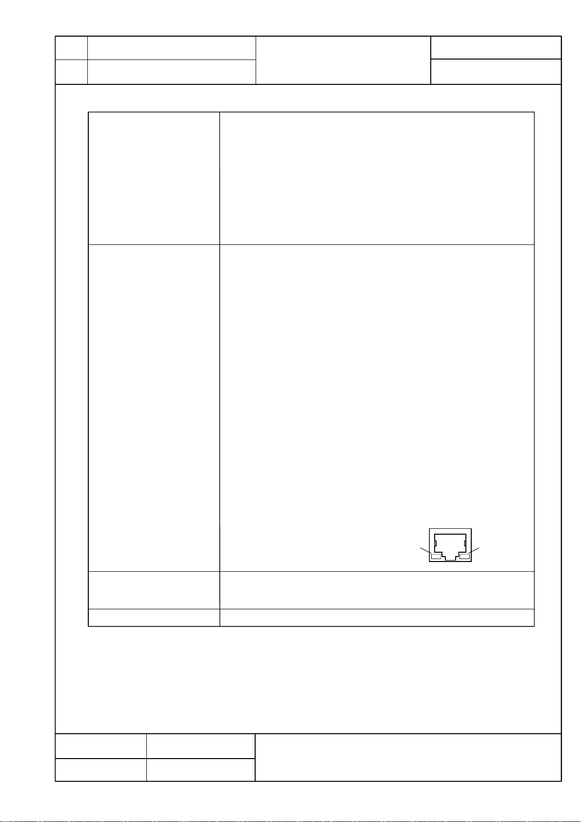
(4) Port LED (Left)
LINK/ACT (ports 1-6) LED
Green Light : Link is established.
Green Blink : Data is being sent/received.
Off : No terminal is connected.
5-4. Cascade connections
5-5. FAN
Date issued
Date revised
(5) Port LED (Right)
Port 1-6 corresponding to the Auto MDI / MDI-X
(Allowed change by the setting for the application)
The factory default is for ports 1 to 4 are fixed to be MDI-X.
Not installed
Nov. 7, 2016
Oct. 1, 2020
PoE (ports 1-4) LED
Green Light : Power is supplied normally.
Green Blink : Overload power supply
Off : Power is not supplied or PoE receiving equipment is not connected.
LED(Left)
LED(Right)
Panasonic Life Solutions Networks Co., Ltd.
Page 4

Model
Name
Model
No.
GA-AS4TPoE+
PN25048-ID
6. Software Specifications
6-1. Configuration It can be set from a remote terminal according to the Web screen.
6-1-1. IP address setting
6-2. Switching Hub Control It can be set from a remote terminal according to the Web screen.
6-3. System reboot It can be reset in the following three modes from software.
6-4. Agent Management protocol : HTTP (RFC 2616)
6-5. Log Maximum retention number : 1,024
6-6. Others
401-25048-ID-SP02
Product Specification
Page 4 of 7
(1) Setting by the Web screen.
(2) Setting by the IP address easy setting function of ZEQUO assist Plus.
Possible to confirm the switch operating status by the following features.
(1) CPU utilization, memory usage display function.
(1) Warm start.
(2) Reset back to the factory default settings.
(3) Reset to return the non-IP address to the factory default setting.
It can be used in combination reboot timer function in each mode
Data transfer protocol : TFTP (RFC 783)
Syslog forwarding function
Ping response (ICMP echo reply) function
Syslog Client (system log sent to a Syslog server)
TFTP Client (Firmware upgrade, save and read of configuration information)
SNTP Client
IP Address Easy Setting
ZEQUO assist Plus support
7. Layer 2 Switching Functions
7-1. Port grouping function
7-2. VLAN IEEE802.1Q tag VLAN protocol
7-3. Link aggregation
7-4. Port Monitoring
7-5. QoS
7-6. PoE power supply function
7-7. Time setting SNMP settings, time manual setting
7-8. Multicast Multicast address group registration function. (can be up to 256 groups of registration)
7-9. Storm control function
It can communicate control only the same group.
(It can be up to 256 groups of registration.)
Port-based VLAN
VLAN registration number 256 (including the default)
Internet Mansion function
VLAN invalid setting function
IEEE802.3ad link aggregation function (Manual)
Configurable up to 3 groups (Max. 6 ports per group)
It can be sent by copying the port where you specify the traffic of the target port.
(A plurality of target port can be specified.)
(Link Aggregation Configuration port can also be monitoring.)
IEEE802.1p 4 stage priority control
Scheduling scheme:
Priority Queuing (PQ: Absolute priority scheduling)
IEEE802.3af/at power supply function.
Up to 62 W of power can be supplied to ports 1 to 4 in total.
(Maximum power supplied to a port: 30 W)
Supply method :Alternative A(Cable signal lines 1, 2, 3, and 6 are used.)
Unknown unicast / Broadcast / Multicast of possible control the storm
Date issued
Date revised
Nov. 7, 2016
Panasonic Life Solutions Networks Co., Ltd.
Oct. 1, 2020
Page 5

Model
Name
Model
No.
GA-AS4TPoE+
PN25048-ID
8. Web management function
8-1. Software specification
8-1-1. Enabled browser
8-2. Setting function
8-2-1. Switching configuration
8-2-2. Time setting
8-3. Monitoring function
8-3-1. Basic information System information, Hardware information,
8-3-2. Learning and recording
information
8-4. System management tools Software upgrade, Reboot, Save current config, Config file transfer, Ping execution
Product Specification
Microsoft Internet Explorer 11
Administration config
IP config
Port config (basic, extend, Power saving)
System security
Syslog transmission config
ID/Password change
Static ARP table
VLAN settings
QoS settings
SNTP setting, manual setting
Management information [Host name (sysName)],
System address information
FDB table, ARP table, Statistics, System log
Link aggregation config
Storm control config
Port monitoring config
Static multicast address config
PoE settings
Port group config
System log config
Exception handler
Watchdog timer
401-25048-ID-SP02
Page 5 of 7
9. Connector Pin Arrangement
9-1. Port 1 - 6
Status
MDI-X
MDI
Pin No.
Signal
Signal
12364
BI_DB+
BI_DA+
BI_DB-
BI_DA-
10. Accessories
10-1. Accessories
10-2. Optional accessories
587
BI_DA+
BI_DB+
(1) Installation Guide :1
(2) CD-ROM (PDF version of Operating Instructions)(*1) :1
(3) Rubber foot :4
(4) Power cord (CEE7/7)(*2) :1
*1 We discontinued the CD-ROM from October 2020's production lots.
*2 The attached power cord is dedicated for AC 100 - 240 V use.
・PN71051 19-inch rack mount brackets (one unit)
・PN71052 19-inch rack mount brackets (two units connected)
・PN71053 wall mount brackets
BI_DA- BI_DD+
BI_DB- BI_DC+
BI_DD-
BI_DC-
BI_DC+
BI_DD+
BI_DC-
BI_DD-
Pin No.
1 2 3 4 5 6 7 8
Date issued
Date revised
Nov. 7, 2016
Panasonic Life Solutions Networks Co., Ltd.
Oct. 1, 2020
Page 6

Model
Name
Model
No.
GA-AS4TPoE+
Product Specification
PN25048-ID
401-25048-ID-SP02
Page 6 of 7
10. Prohibitions when Using the Product to Guarantee Safety
The manufacturer assumes no responsibility for any problems occurring when the following conditions are not satisfied.
Observe the following items when using the product.
(1) Do not use power supply other than AC 100 - 240 V.
Deviation could lead to fire, electric shock, and/or equipment failure.
(2) Do not handle the power cord with wet hand.
Deviation could lead to electric shock, and/or equipment failure.
(3) Do not handle this Switching Hub and connection cables during a thunderstorm.
Deviation could lead to electric shock.
(4) Do not disassemble and/or modify this Switching Hub.
Deviation could lead to fire, electric shock, and/or equipment failure.
(5) Do not damage the power cord. Do not bend too tightly, stretch, twist, bundle with other cord, pinch, put under a heavy
object and/or heat it.
Damaged power cord could lead to fire, and/or electric shock.
(6) Do not insert, nor drop foreign objects such as metal or combustible things into the inside from the openings or twisted pair ports.
Deviation could lead to fire, electric shock, and/or equipment failure.
(7) Do not connect equipments other than 10BASE-T/100BASE-TX/1000BASE-T to twisted pair port.
When connecting to a 10BASE-T device, use a Cat5 or above cable.
Deviation could lead to fire, electric shock, and/or equipment failure.
(8) Do not place this Switching Hub in harsh environment (such as near water, high humid, and/or high dust).
Deviation could lead to fire, electric shock, and/or equipment failure.
(9) Do not place this Switching Hub under direct sunlight and/or high temperature.
Deviation could lead to high internal temperature and fire.
(10) Do not install this Switching Hub at the location with continuous vibration or strong shock, or at the unstable location.
Deviation could lead to falling, injury and/or equipment failure.
(11) Do not put this Switching Hub into fire.
Deviation could lead to explosion and/or fire.
Date issued
Date revised
Nov. 7, 2016
Panasonic Life Solutions Networks Co., Ltd.
Oct. 1, 2020
Page 7

Model
Name
Model
No.
GA-AS4TPoE+
Product Specification
PN25048-ID
11. Basic Instructions for the Use of This Product
(1) Use the bundled power cord (AC 100 – 240 V specifications).
Deviation could lead to electric shock, malfunction, and/or equipment failure.
(2) Unplug the power cord in case of equipment failure.
Deviation, such as keeping connected for a long time, could lead to fire.
(3) Connect this Switching Hub to ground.
Otherwise this might cause electrical shocks, misoperations and malfunctions.
Connect the Switching Hub via the supplied power cord to the outlet which is connected to the ground.
If the outlet is not connected to a ground, connect the ground cable (AWG18:green/yellow) to the ground terminal screw.
(4) Connect the power cord firmly to the power port.
Deviation could lead to electric fire, shock, and/or malfunction.
(5) If the STATUS (Status) LED blinks orange, unplug the power cord since this is a malfunction.
Deviation, such as keeping connected for a long time, could lead to fire.
(6) Handle the Switching Hub carefully so that fingers or hands may not be damaged by twisted pair port or power cord hook block.
(7) When connecting IEEE802.3at-enabled receiving equipment to the Switching Hub, use a CAT5e or above cable. Using cables
other than those could lead them to cause heat to be generated, to catch on fire and/or cause malfunctions.
401-25048-ID-SP02
Page 7 of 7
(8) When mounting the Switching Hub on a wall, mount it securely using wall mount brackets (PN71053, optional) to prevent the
Switching Hub from falling due its weight and that of the connection cables.
Injuries and/or malfunctions could be caused due to the Switching Hub falling, etc.
(9) Up to two Switching Hubs can be connected. When connecting two Switching Hubs, use connection brackets and screws (for
fixing the connection brackets) supplied with 19-inch rack mount brackets (two coupled units)( PN71052, optional) to securely fix
the connection brackets to the connection screw holes on the front and back panels, and then install the Switching Hubs. If the
Switching Hub is not fixed securely, injuries and/or malfunctions could be caused due to the Switching Hub falling, etc.
(10) This Switching Hub is to be periodically serviced in order to maintain its performance.
Please choose a product administrator, and have them be sure to implement periodic maintenance. When doing maintenance,
check the inspection chart that is posted on our website which has the requisite items listed on it.
(11) When using this Switching Hub to design systems, use it after applying appropriate measures such as setting up redundant
configurations.
Communications failures might be generated due to causes such as malfunctions or misoperations while the Switching Hub is
being used.
(12) When using this Switching Hub for applications which require extremely high reliability, be careful to expend all possible means
to ensure safety and reliability.
This Switching Hub was not designed nor manufactured with the intention that it be used for applications (in use with railways,
aviation, and medical care, etc.
whereas the influence rate due to communications failures is extremely high in regard to systems that directly affect systems and
human lives) which require extremely high reliability.
(13) Be aware of glitches which are caused in the usage environments such as age-related degradation, etc.
This may vary depending upon conditions such as utilisation rates and usage environments, but performance might decrease due
to the age-related degradation, etc. of components. It is recommended that this Switching Hub be replaced about five years
after it has been installed.
(14) Be careful in regards to environmental restrictions whereby the Switching Hub can be used.
Please isolate the business power lines and communications lines. Isolate distribution lines and other distribution lines, and low
current power lines, optical fiber cables, metallic water conduits, and gas conduits, etc. Noise may be generated in the
communications lines which might cause communications glitches.
Date issued
Nov. 7, 2016
Panasonic Life Solutions Networks Co., Ltd.
Date revised
Oct. 1, 2020
 Loading...