

Page 1
SIMPLE VENTILATION SOLUTIONS
AirCycler® g2-k
Installation & User’s Guide
VENTILATION MADE BREEZY!™
a breeze to install • a breeze to use
Page 2

TABLE OF CONTENTS
AirCycler® g2-k Introduction
Safety Considerations
Installation Considerations
AirCycler® g2-k Wiring Diagram
Damper Location & Damper Installation
Choose a Fresh Air Location
AirCycler® g2 Controller Location
1.0 Theory of Operation
1.1 Operation Details
1.2 Operation Examples
2.0 AirCycler® g2 Operation
2.1 Reading the AirCycler® g2
2.2 Normal Operation Display
2.3 Entering Setup Mode
3.0 Setup Options
4.0 Calculated Flow Set Up
4.1 Setting Measured Supply Air Flow
4.2 Setting Measured Exhaust Air Flow
4.3 Setting Code Required Constant Air Flow
4.4 Setting Optional Mixing Time
4.5 Setting Operation Hours
4.6 Setting Exhaust Fan Delay Time
5.0 Calculated Time Set Up
5.1 Setting Number of Minutes Per Hour of Supplied Air Flow
5.2 Setting Minutes of Exhaust Fan Run Time Required
5.3 Setting Optional Mixing Time
5.4 Setting Operation Hours
5.5 Setting Current Time
5.6 Setting Exhaust Fan Delay Time
6.0 Viewing Current Status & Settings
6.0 Currrent Status
6.1 Current Settings
6.2 Setting Current Time
7.0 Installation Testing Guide
Appendix A: Troubleshooting & Tips
Appendix B: ASHRAE 62.2 Reference Chart
Page 3

AIRCYCLER® G2-K INTRODUCTION
The AirCycler® g2-k Whole House Mechanical Ventilation System includes the AirCycler® g2 Furnace Fan Timer,
FanConnect™ Bath/Fan Light Switch with remote fan control, and a motorized fresh air damper.
The AirCycler® g2 is a furnace fan timer and ventilation controller with outputs for operating a motorized fresh air
damper and the FanConnect™ exhaust fan switch*. This product provides whole house supply ventilation through cen-
tral furnace fan integration as well as whole house exhaust ventilation.
SAFETY CONSIDERATIONS
Read and follow manufacturer’s instructions carefully. Follow all local electrical codes during installation. All wiring
must conform to local and national electrical codes. Improper wiring or installation may result in personal injury or
product and property damage.
INSTALLATION CONSIDERATIONS
The AirCycler® g2 requires 24VAC (R and C terminals) to be connected for proper operation. The controller will not
operate without these two connections.
The wires (R, C, & W ) from the air handler to the thermostat can run parallel with the wiring from the AirCycler®
g2 to the air handler. The fan wire (G) must be interrupted by the AirCycler® g2. Some thermostats do not require a
common (C) connection. The AirCycler® g2 requires this for power, which must be wired to the furnace.
RECORD ALL SETTINGS ON THE INSTALL STICKER PROVIDED. LIMITED
WARRANTY WILL BE VOID IF THE STICKER IS NOT PRESENT.
3
AC DOC 8.5
REV 10/24/2014
Page 4
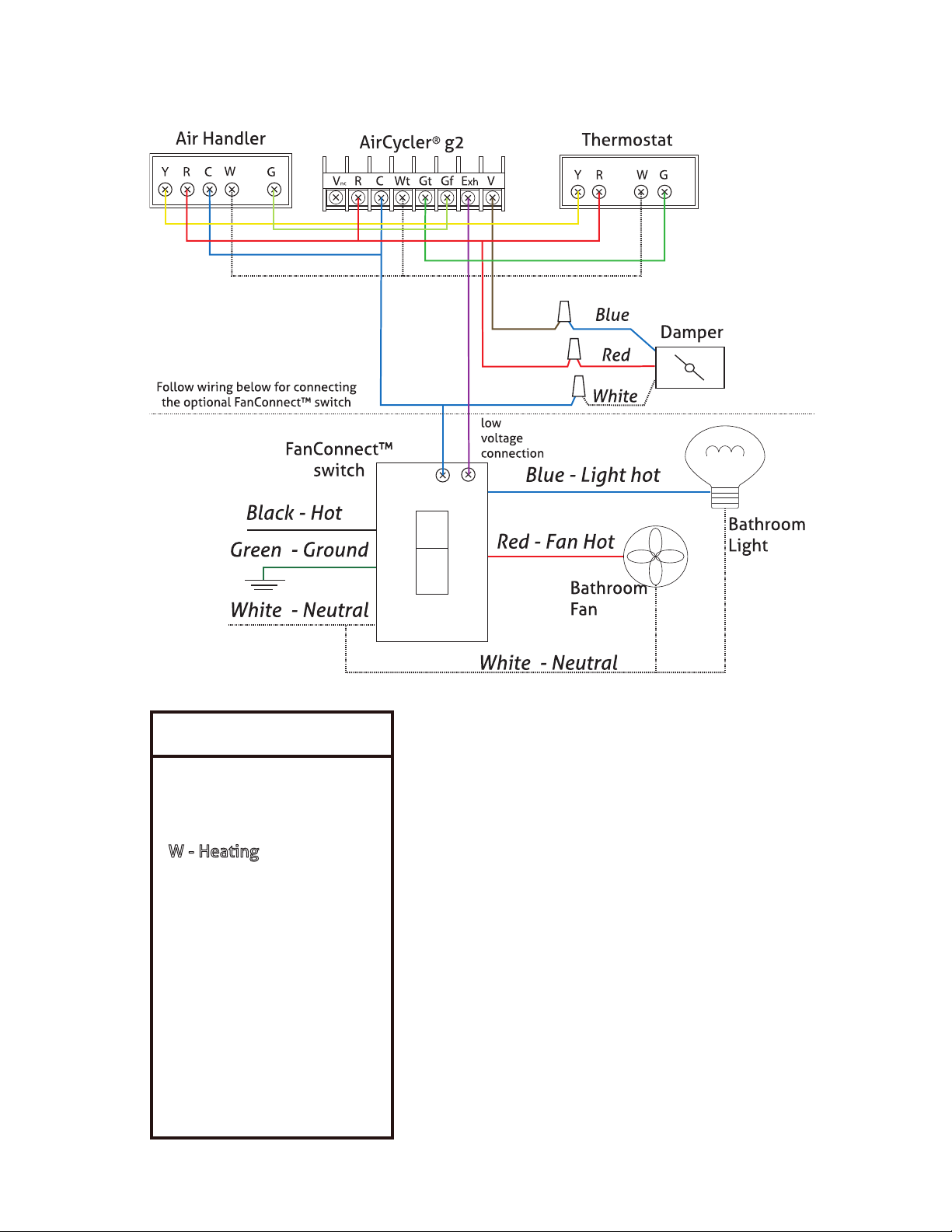
AIRCYCLER® G2-K WIRING DIAGRAM
KEY
R - 24VAC Power
C - Common
Gt - Fan From Thermostat
Gf - Fan To Furnace
V - Vent
Ex - Exhaust Fan
Vnc - Normal Closed Vent
(To power spring-return
dampers that are
normally open)
4 AC DOC 8.5
REV 10/24/2014
Page 5
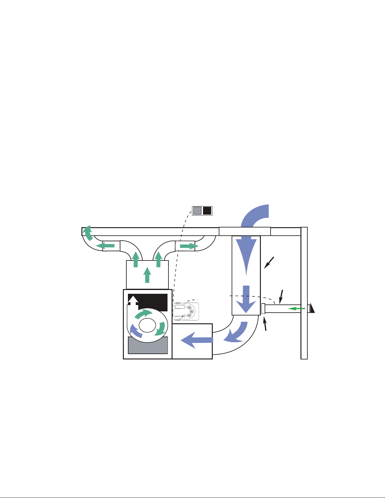
DAMPER LOCATION
The fresh air damper can be located anywhere in the inlet duct. Minimize the length of the inlet duct to improve air
ow and improve system eciency. It is recommended that the damper be as close to the return air plenum and the
AirCycler® g2 controller as possible, and the inlet duct connect to the return plenum upstream of the system lter, and
down- stream of any duct mounted sensors.
DAMPER INSTALLATION
The damper may be installed in any position. It is recommended to install it with the motor at the12 o’clock position if
mounted horizontally. Air may ow through in either direction, although it is recommended to install with the crimped
end as the outlet. Use care to avoid distorting the damper housing and provide adequate support.
CHOOSE A FRESH AIR LOCATION
ASHRAE recommends that the fresh air intake be located at least 10 ft. from any source of pollutants, such as auto
exhaust, dryer exhaust, exhaust from any fuel-burning appliances, etc. Avoid installation near odor sources such as
garbage bins or barbecue grills. A minimum of 3 ft. above ground is recommended to avoiding ingress of leaf litter,
grass clippings, etc. Do not use a crawl space, basement, or attic as a source of intake air. Always be sure to comply with
local building codes and requirements regarding fresh air inlets.
Thermostat
AirCycler®
G2
Filter
Main Return
Duct
Motorized
Damper
Outside
Air Duct
AIRCYCLER® g2 CONTROLLER LOCATION
The AirCycler® g2 controller can be installed near the thermostat or out of view on/near the air handler unit. See the
wiring diagram on page 4.
Warning: Before installing the AirCycler®, turn o all power to the furnace. There may be more than one power to disconnect.
Electrical shock can cause injury or death.
5
AC DOC 8.5
REV 10/24/2014
Page 6
1.0 THEORY OF OPERATION
No need for additional ventilation forced by AirCycler® g2.
1.1 OPERATION DETAILS
The AirCycler® g2 Furnace Fan Timer is integrated with the home’s central furnace fan so that any time the central
fan is turned on by the thermostat to provide heating or cooling, the AirCycler® g2 opens the motorized damper to
let in a measured amount of fresh air. The fresh air is then distributed uniformly throughout the home through the
existing ductwork.
When ventilation requirements are met, the damper is closed to prevent over-ventilation.
Should regular heating and cooling cycles not run long enough to meet the desired or required ventilation, the
AirCycler® g2 can turn on the smaller and more economical bathroom exhaust fan (or other exhaust fan) through the
optional FanConnect™ Switch.
With no need to run the large central fan to provide additional ventilation, homeowner complaints of cold air or noisy
operation are eliminated and eciency is drastically improved.
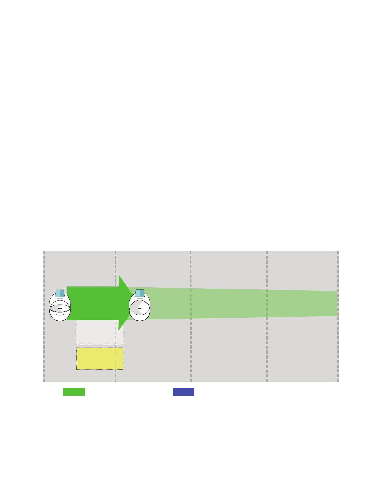
1.2 OPERATION EXAMPLES
ONE HOUR VENTILATION (MINUTES)
VENTILATION REQUIREMENTS = 30 CFM CONTINUOUS OR 1,800 CF/HR
NORMAL CENTRAL FAN OPERATION ONLY
0
15
30
45
CENTRAL FAN
DAMPER
OPEN
20 MINUTES OF
HEATING/COOLING
20 MIN x 90 CFM
= 1,800 CF
VENTILATION
REQUIREMENT
COMPLETE
= NORMAL OPERATION
Enough ventilation took place during normal heating/cooling cycles to meet ventilation requirements for the hour.
DAMPER
CLOSED
= OCCUPANT ACTIVITY/AIRCYCLER® G2 FORCED EXHAUST
60
6 AC DOC 8.5
REV 10/24/2014
Page 7

1.2 OPERATION EXAMPLES CONT’D
VENTILATION REQUIREMENTS = 30 CFM CONTINUOUS OR 1,800 CF/HR
NORMAL CENTRAL FAN OPERATION + AIRCYCLER® G2 FORCED EXHAUST
ONE HOUR VENTILATION (MINUTES)
0
15
30
CENTRAL FAN
DAMPER
OPEN
15 MINUTES OF
HEATING/COOLING
15 MIN x 90 CFM
= 1,350 CF
= NORMAL OPERATION
DAMPER
CLOSED
= OCCUPANT ACTIVITY/AIRCYCLER® G2 FORCED EXHAUST
45
EXHAUST FAN
DAMPER
OPEN
7.5 MIN x 60 CFM = 450 CF
450 CF + 1,350 CF = 1,800 CF
After regular heating/cooling cycles, ventilation requirements for the hour were not met. At the end of the hour the
AirCycler® g2 forced on the bathroom exhaust fan, via the FanConnect™ switch, to reach required ventilation.
FORCED ON
BY G2 VIA
FANCONNECT
FOR 7.5 MIN
VENTILATION
REQUIREMENT
COMPLETE
60
DAMPER
CLOSED
NORMAL CENTRAL FAN OPERATION + OCCUPANT EXHAUST USE
0
CENTRAL FAN
DAMPER
OPEN
10 MINUTES OF
HEATING/COOLING
10 MIN x 90 CFM
= 900 CF
= NORMAL OPERATION
15
DAMPER
CLOSED
30
EXHAUST FAN
= OCCUPANT ACTIVITY/AIRCYCLER® G2 FORCED EXHAUST
After regular heating/cooling cycles and manual occupant use of bathroom exhaust fan, ventilation requirements for the
hour were met. No need for additional ventilation forced by AirCycler® g2.
45
DAMPER
OPEN
15 MIN x 60 CFM = 900 CF
900 CF + 900 CF = 1,800 CF
15 MIN OF
BATHROOM USE
(MANUAL USE
OF FANCONNECT
SWITCH)
VENTILATION
REQUIREMENT
COMPLETE
DAMPER
CLOSED
60
7
AC DOC 8.5
REV 10/24/2014
Page 8

1.2 OPERATION EXAMPLES CONT’D
VENTILATION REQUIREMENTS = 30 CFM CONTINUOUS OR 1,800 CF/HR
NORMAL CENTRAL FAN OPERATION + OCCUPANT EXHAUST USE + AIRCYCLER® G2 FORCED EXHAUST
ONE HOUR VENTILATION (MINUTES)
DAMPER
CLOSED
45
EXHAUST FAN
DAMPER
OPEN
FORCED ON
BY G2 VIA
FANCONNECT
FOR 5 MIN
5 MIN x 60 CFM
= 300 CF
60
0
CENTRAL FAN
DAMPER
OPEN
10 MINUTES OF
HEATING/COOLING
10 MIN x 90 CFM
= 900 CF
15
DAMPER
CLOSED
30
EXHAUST FAN
DAMPER
OPEN
BATHROOM USE
(MANUAL USE
OF FANCONNECT
(5 MIN + 5 MIN) x 60 CFM
5 MIN OF
5 MIN
DELAY
SWITCH)
= 600 CF
900 CF + 600 CF
+ 300 CF = 1,800 CF
VENTILATION
REQUIREMENT
COMPLETE
= NORMAL OPERATION
= OCCUPANT ACTIVITY/AIRCYCLER® G2 FORCED EXHAUST
After regular heating/cooling cycles and manual occupant use of bathroom exhaust fan (including 5 minute delay), there was not enough
ventilation to meet requirements for the hour. At the end of the hour the AirCycler® g2 forced on the bathroom exhaust fan, via the
FanConnect™ switch, to reach required ventilation.
8 AC DOC 8.5
REV 10/24/2014
Page 9

2.0 AIRCYCLER® G2 OPERATION
2.1 READING THE AIRCYCLER® G2
G2 DISPLAY KEY
OPERATION
SETUP/STATUS
OA
EXH
FAN
ON
%
CFM
SET
REQ
TIME
HR
MIN
AM
PM
Damper Open
Exhaust Fan On
Central Fan On
G2 Operation On (Forcing Central Fan On)
Percent Ventilate Complete for Hour
Air Flow Cubic Feet Per Minute Values
Setup Mode
Required CFM Setting
Time Setting Mode
Hour
Minutes
Time - AM
Time - PM
2.2 NORMAL OPERATION DISPLAY
Normal display will show the percentage of the current
ventilation cycle (hour) that is complete.
FUNCTIONS APPLY WHEN ICONS ARE
ACTIVE/ILLUMINATED
THE DAMPER
THE EXHAUST
FAN IS ON
IS OPEN
LCD DISPLAY
If the central fan is running from a thermostat call, the
FAN icon will show.
THE THERMOSTAT
HAS TURNED ON
THE CENTRAL FAN
If the AirCycler® g2 has forced on the central fan, the
FAN and ON icons will show.
THE AIRCYCLER® G2
HAS FORCED THE FAN
PERCENTAGE OF
VENTILATION COMPLETE
If the exhaust (bath) fan is on, the EXH icon will show.
If the outside fresh air damper is open the OA icon will show.
If the EXH fan is running its set delay time after the FanConnect™ has been turned o, the delay time countdown as
well as the MIN and EXH icons will show.
2.3 ENTERING SETUP MODE
Once wiring is complete, place the controller on the base. All icons will be illuminated for 3 seconds.
Press the UP arrow within 3 seconds of power up to enter Calculated Flow Setup
Press the DOWN arrow within 3 seconds of power up to enter Calculated Time Setup
If a set up method was not selected within 3 seconds, remove controller from base and replace to re-enter setup mode.
9
AC DOC 8.5
REV 10/24/2014
Page 10

3.0 Setup Options
Calculated Flow
Setup
Enter measured outside
airflow to the air handler
Enter measured
exhaust flow
*If using FanConnect™ switch
Enter required continuous
airflow required by code
Calculated Time
Setup
Enter required minutes per
hour of ventilation
Enter min/hour of exhaust
ventilation desired
*If using FanConnect™ switch
Calculated Flow
If you know the amount of fresh air that
goes into the air handler as well as the
ow required by code, you can simply
enter them into the AirCycler® g2
controller during set up.
Calculated Time
If you’d prefer to congure the amount
of time you want fresh air ventilation per
hour, you can enter the total minutes per
hour into the AirCycler® g2 during set
up.
NO
Enter optional
mix time
Do you want to
set ventilation
hours?
Set desired hours
of operation
Set current
time
Enter desired delay time
*If using FanConnect™ switch
YES
END
Begin normal
operation
10 AC DOC 8.5
REV 10/24/2014
Page 11

4.0 CALCULATED FLOW SET UP
4.1 SETTING MEASURED SUPPLY AIR FLOW
The measured ow is the amount of air that enters the return
side of the air handler from the outside air vent. Enter the
measured ow. To accommodate variable speed air handlers,
you can enter dierent values for heat, cool and fan. Factory
default is 90 CFM.
Press MODE to advance to the next setting.
Flow measured
during heat call
Flow measured during
cooling call
Flow measured during
fan only call
*Only if FanConnect™ switch is not
connected
4.2 SETTING MEASURED EXHAUST AIR FLOW
Enter the measured ow from the exhaust fan. Factory default is 60 CFM. If the
FanConnect™ switch is not detected, make sure it is in the OFF position
Press MODE to advance to the next setting.
4.3 SETTING CODE REQUIRED CONSTANT AIR FLOW
Set the required continuous air ow in CFM based on relevant codes. For ASHRAE 62.2
see Appendix B. Factory default is 30 CFM. The AirCycler® g2 will calculate run times
based on settings 4.1 and 4.2.
Press MODE to advance to the next setting
Alternating
Display
Press: MODE
Alternating
Display
Press: MODE
Alternating
Display
Press: MODE
4.4 SETTING THE OPTIONAL MIXING TIME
If the user needs more central fan time for whole house mixing than the amount that is
provided by ventilation time, the central fan can be congured to run an additional time
period to complete the mixing period. Factory default is 0 or OFF. The fresh air damper
will not be open during this extra time.
Press MODE to advance to next setting.
4.5 SETTING OPERATION HOURS
If the user does not want the ventilation system to run constantly, you can set ON time
and OFF time. Factory default is OFF.
Press MODE to advance to the next setting.
4.6 SETTING EXHAUST FAN DELAY TIME
Set the desired length of time you want the exhaust fan to run after the FanConnect™
switch has been turned o. Factory default is 10 minutes.
Press MODE to save all settings and return to normal operation.
CALCULATED FLOW SETUP IS COMPLETE
The AirCycler® g2 will now return to normal operation.
11
AC DOC 8.5
REV 10/24/2014
Page 12

5.0 CALCULATED TIME SETUP
5.1 SETTING NUMBER OF MINUTES PER HOUR OF SUPPLIED AIR FLOW REQUIRED
Enter the minutes per hour that you require fresh air to be brought into the home. Factory
default is 20 minutes. Press MODE to advance to the next setting.
For installations without the FanConnect™ switch, go to section 5.4.
5.2 SETTING MINUTES OF EXHAUST FAN RUN TIME REQUIRED
Enter the desired minutes/hour for exhaust fan run time. Factory default is 20 minutes.
If the FanConnect™ switch is not detected, make sure it is in the OFF position. Press MODE.
5.3 SETTING OPTIONAL MIXING TIME
If the user needs more central fan time for whole house mixing than the amount that is
provided by ventilation time, the central fan can be congured to run an additional time
period to complete the mixing period. Factory default is 0 or OFF. The fresh air damper
will not be open during this extra time. Press MODE to advance to the next setting.
5.4 SETTING OPERATION HOURS
If the user does not want the ventilation system to run constantly, you can set ON time
and OFF time. Factory default is o.
If you are not setting an ON and OFF time, press MODE and continue to section 5.6.
If you select YES, the AirCycler® g2 will prompt you to enter the hour you would like the
ventilation to begin and the hour you want it to end followed by the current time.
Set the hour for ventilation to START. Press MODE to advance to the next setting.
Set the hour for ventilation to STOP. Press MODE to advance to the next setting.
5.5 SETTING CURRENT TIME
Enter the current time. Press MODE to advance to the next setting.
If you are not connecting a FanConnect™ switch, Press MODE until Normal Operation is
resumed. CALCULATED TIME SETUP IS COMPLETE
5.6 SETTING EXHAUST FAN DELAY TIME
Set the desired length of time you would like the bath fan to run after the FanConnect™
has been turned o. Factory default is 10 minutes.
Press the DOWN arrow until the countdown reaches 0 then SL (SL= slave mode). In slave
mode the exhaust fan runs anytime the central fan is running with the fresh air damper
open. Slave mode will provide a “balanced” mode of operation.
N
Press MODE to save all settings and return to normal operation.
CALCULATED TIME SETUP IS COMPLETE.
The AirCycler® g2 will now return to normal operation.
12 AC DOC 8.5
REV 10/24/2014
Page 13

6.0 CURRENT STATUS & SETTINGS
To get detailed information on the current status of the
AirCycler® g2, press the UP arrow. The status screens are the
same for both Calculated Flow and Calculated Time modes.
Press the UP arrow to advance to each setting.
To view the current settings, press the DOWN arrow during
Normal Operation. Press the DOWN arrow to advance to each
setting.
Pressing the MODE button will take you to current time
settings.
6.0 CURRENT STATUS
MINUTES LEFT
The rst display is the number of minutes left in the period (hour).
OUTSIDE AIR TIME ELAPSED
This display shows the number of minutes this period that the outside air damper has
been open with the central fan running.
PRESS THE UP
ARROW FOR CUR-
RENT STATUS
PRESS THE MODE
BUTTON TO CYCLE
THROUGH THE CUR-
RENT TIME OF DAY
PRESS THE DOWN
ARROW TO VEW THE
CURRENT SETTINGS
EXHAUST RUN TIME (If using FanConnect™ switch)
This shows the elapsed run time of the exhaust fan for this time period.
EXHAUST DELAY TIME (If using FanConnect™ switch)
This shows the exhaust delay time set.
6.1 CURRENT SETTINGS
To view the current settings that are programmed in the AirCycler® g2, press the DOWN arrow during Normal Operation.
Press the DOWN arrow to advance to each setting. The display will show the following:
For Calculated Flow mode the screens will show:
• Required CFM set
• Set measured outside air CFM
• Set measured exhaust air CFM
• Set exhaust fan delay time
*If optional FanConnect™ is connected
For Calculated Time mode the screens will show:
• Exhaust run time set*
• Outside air time in minutes
• Exhaust fan delay time*
• If operating time is enabled:
• Operating Time On
• Operating Time O
6.2 SETTING CURRENT TIME
By pressing the MODE key you will cycle through current time of day and will be able to change it if needed.
Note: There is no need to set the current time if you’re not using operation hours.
13
REV 10/24/2014
AC DOC 8.5
Page 14

RECORD ALL SETTINGS ON THE INSTALL STICKER
PROVIDED. LIMITED WARRANTY WILL BE VOID IF THE
STICKER IS NOT PRESENT.
14 AC DOC 8.5
REV 10/24/2014
Page 15

7.0 INSTALLATION TESTING GUIDE
Testing the AirCycler® g2-k completed installation is an easy two step process:
STEP 1 Test the FanConnect
(tm)
connection & operation (if using FanConnect™ switch)
STEP 2 Test thermostat, damper and furnace connection and operation
STEP 1
a. With the thermostat o, turn on the FanConnect™
switch.
b. Conrm the exhaust fan is running
c. The AirCycler® g2 display should show the exhaust (bath)
fan is ON and the outside fresh air damper is open (OA)
d. Conrm the outside fresh air damper is open (OA icon)
e. Turn o exhaust fan
EXH - EXHAUST
FAN IS ON
STEP 2
LCD DISPLAY
OA - FRESH AIR DAMPER
IS OPEN
PERCENTAGE OF VEN-
TILATION COMPLETE
a. Make sure exhaust fan is o (delay time may be running and
EXH icon will show)
b. Turn thermostat FAN switch to ON
c. Conrm AirCycler® g2 display shows FAN and damper
open (OA).
d. Conrm furnace fan is running
e. Remove AirCycler® g2 from it’s base. Furnace fan should
shut o
f. DONE! Replace AirCycler® g2 controller on it’s base
EXH
FAN ON FROM
THERMOSTAT
OA - FRESH AIR DAMPER
IS OPEN
PERCENTAGE OF VEN-
TILATION COMPLETE
15
AC DOC 8.5
REV 10/24/2014
Page 16

APPENDIX A
TROUBLESHOOTING
Problem: No power to AirCycler® g2
Check common wire connection. “C” must be connected to “C” on the furnace.
Problem: EXH icon is ashing
If the EXH icon is ashing it is indicating that the FanConnect™ switch has been on for more than four hours or has lost
connection with the AirCycler® g2 controller.
Problem: Furnace fan is running constantly
Make sure the thermostat FAN switch is set to AUTO and not ON
Problem: Central fan does not shut o when AirCycler® g2 is removed from base (when thermostat fan switch is on)
Check wiring - “G” wire from thermostat should be wired to “Gt” on AirCycler® g2. “Gf” on AirCycler® g2 should be
connected to “G” on furnace.
Problem: Blank Display on the AirCycler® g2
Conrm:
1. The furnace has power
2. The thermostat is operational
3. The furnace will call for heat from the thermostat
4. The fan operates with a fan only signal from the thermostat
5. The furnace is providing 24 VAC to the AirCycler® g2
6. Verify wiring conforms to wiring diagram
7. Make sure cover is rmly seated on the base
Problem: AirCycler® g2 turns furnace fan on and o, but the motorized damper does not cycle.
Conrm:
1. The AirCycler® g2 is providing a 24 VAC signal to the motorized damper
2. The 24 VAC motorized damper is operational by powering directly with a 24 VAC signal
3. There is continuity in the wiring between the damper and the AirCycler® g2
Problem: A/C turns on during fan cycling calls
Conrm:
1. Wiring conforms to wiring diagram
2. The G wire is properly connected
3. The G wire needs to be interrupted by the AirCycler® g2
4. Do not run the G wire in parallel
Problem: The AirCycler® G2 does not detect the optional FanConnect™ switch
Conrm:
1. Verify the FanConnect™ has power and is in the OFF position
TIPS
1. Make sure the FanConnect™ switch is in the OFF position when the AirCycler® g2 is rst powered on.
2. Setup is easier to start without the battery installed. The battery is only used for the real time clock. If you
are not using the operating hours setting, the battery is not needed.
3. To set the AirCycler® g2 to “Inverse Slave Mode” - run the exhaust fan whenever the central fan is not running - enter
Calculated Flow setup. Set Measured Supply Air Flow, Measured Exhaust Air Flow, and Required Constant Airow to the
same levels. For example, set all to 60 CFM.
16 AC DOC 8.5
REV 10/24/2014
Page 17

APPENDIX B
ASHRAE 62.2 REFERENCE CHART
No. of Bedrooms
Square Footage
CFM Required:
7.5 CFM * (N+1) + A * 0.01
N = No. of Bedrooms A = Square Footage
Technical Support:
1.877.FAN.CONTrol
17
AC DOC 8.5
REV 10/24/2014
 Loading...