

Page 1
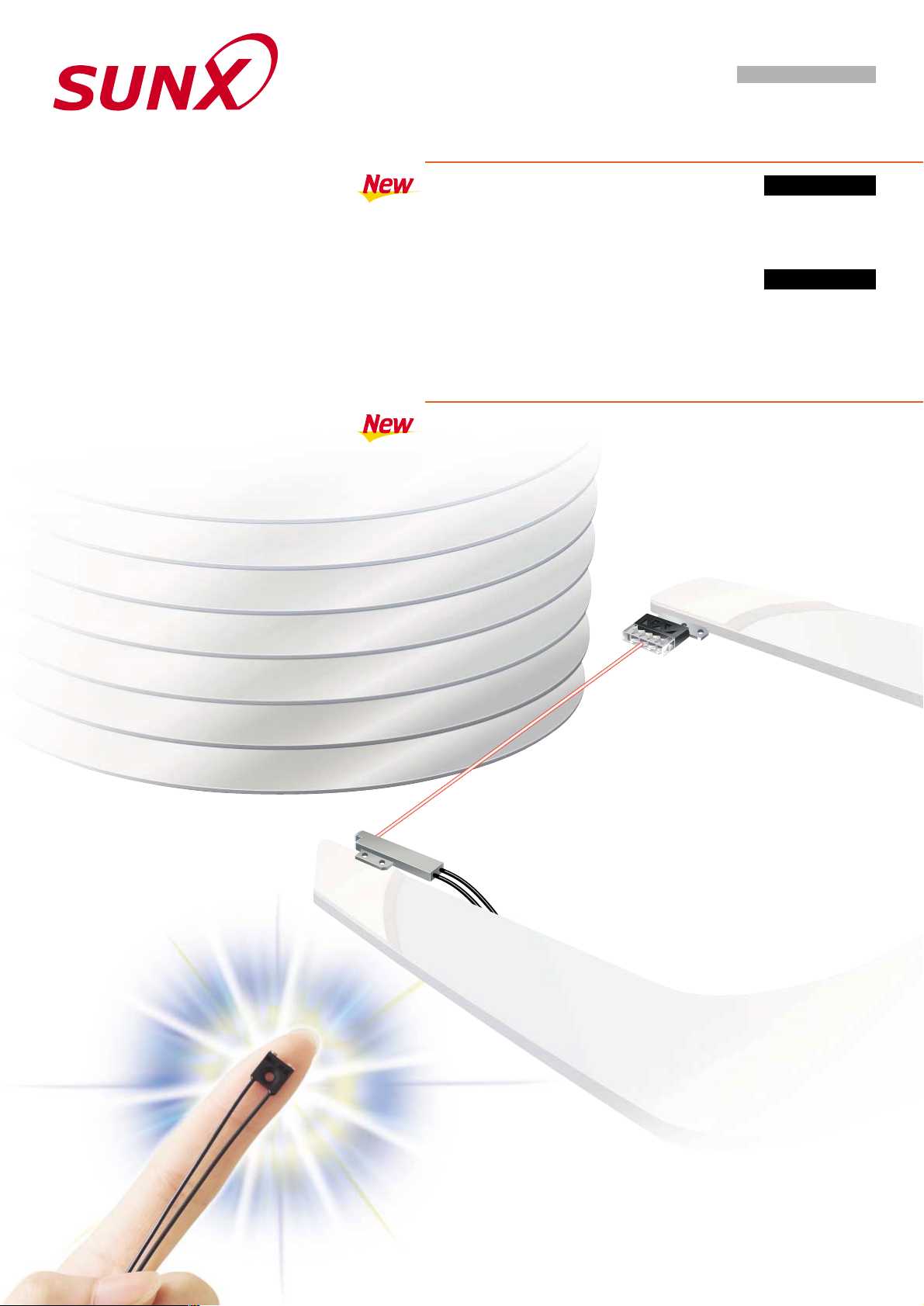
FR-KV1SERIES
FT-KV1SERIES
WAFER MAPPING FIBER
FD-WL48
ULTRA-COMPACT FIXED-FOCUS REFLECTIVE FIBER
OPTICAL FIBER HEAD
Retroreflective Type
Thru-beam Type
Retrorefelctive type mapping fiber
with ultra-thin 2.2 mm 0.087 in
body and easy beam axis alignment
FR-KV1
Ultra-compact size
W7.2H7.5D2 mm W0.283H0.295D0.079 in
FD-WL48
Page 2
4 mm
0.157 in
2 mm
0.079 in
7.5 mm
0.295 in
Extended reflector
angular deviation
characteristics
2.2 mm
0.087 in
11.2 mm
0.441 in
Fiber head
Reflector
Ultra-thin retroreflective type reduces construction work
2.0 mm 0.079 in fiber head and an ultra-thin 2.2 mm 0.087 in reflector allow
these to be mounted even in thin robot hands. Furthermore, because they are
retroreflective type fibers, the amount of wiring needed can be reduced, and
the robot hands require less processing and so can be kept strength.
Ultra-narrow beams and extended angular deviation characteristics
A retroreflective type fiber is used, so that an aperture angle of less than 3
produces an ultra-narrow beam, but still with extended angular deviation
characteristics compared to thru-beam types. This allows stronger curvatures
in robot hands and reduces the work required for beam axis alignment.
Retroreflective type
Retroreflective type
Heat-resistant type available
Resistant to temperatures of 105 C 221 F, so that the robots can be
used with confidence for wafer transportation immediately after heat
processing.
Extended sensing range
A sensing range of 250 mm 9.843 in (in STD mode) allows easy
mapping of 300 mm 11.811 in wafers.
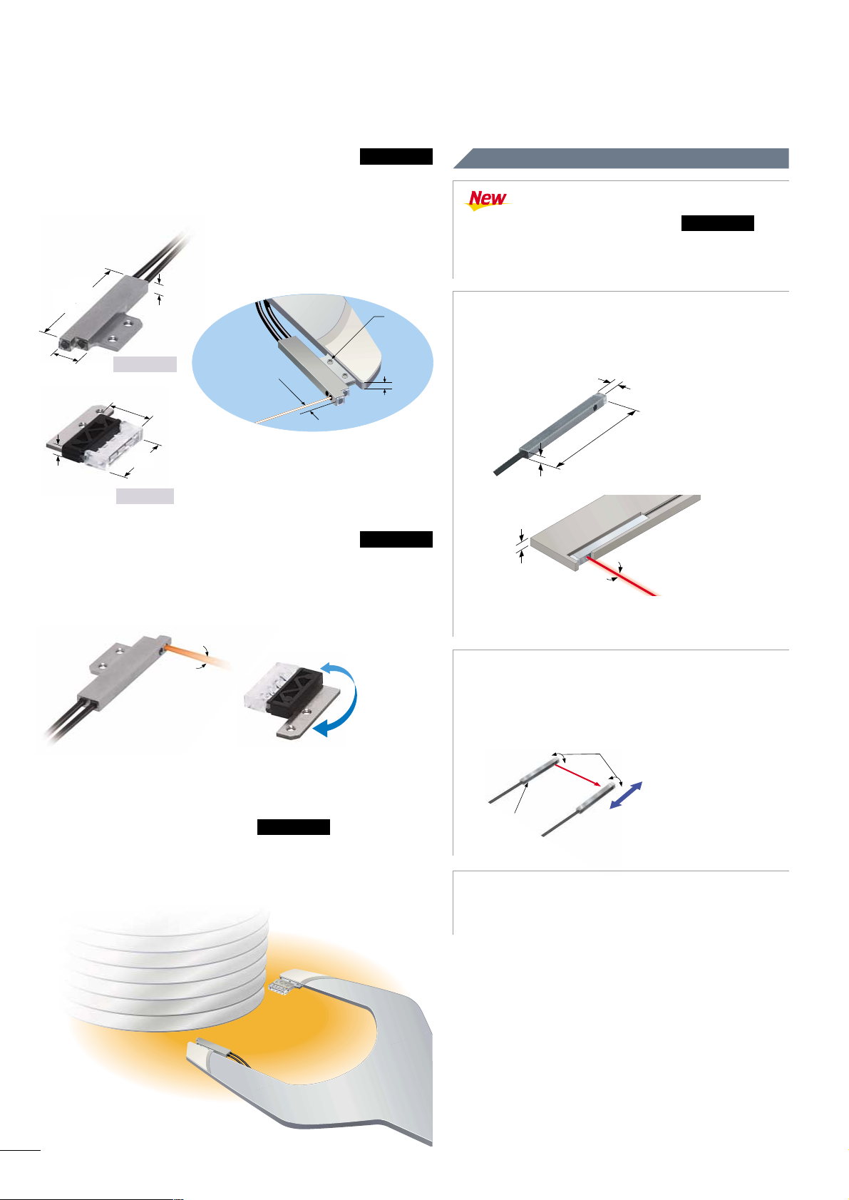
Reduces work required for beam axis alignment
In order to reduce the amount of work required for
mounting, beam axis alignment for the fiber head relative
to the mounting reference surface is carried out at the
time of assembly.
With the FT(-H10)-KV1, the fiber can be embedded
into a plate with a thickness of 2 mm 0.079 in.
Ultra-compact size
The ultra-compact size of W2H1.5D20 mm W0.079
H0.059D0.787 in means that mounting is possible even in
places such as robot hands where space is limited.
Heat-resistant type available
Resistant to temperatures of 105 C 221 F, so that it can
be used with confidence for wafer transportation immediately
after heat processing.
FR-H10-KV1
FR-KV1 can be mounted
to robot hands with
thicknesses of 2.2 mm 0.087 in
2.2 mm
0.087 in
M1.4 screw
mounting
Only 2 mm 0.079 in
from tip of the fiber head
to the beam axis
21.5 mm
0.846 in
Aperture angle 3
Thru-beam type fiber
FT-KV1 / FT-H10-KV1
Beam axis alignment for the fiber head
relative to the mounting reference surface is
carried out at the time of assembly.
FT-H10-KV1
2 mm
0.079 in
2 mm
0.079 in
20 mm
0.787 in
1.5 mm
0.059 in
Aperture angle 3
Beam axis alignment complete
Mounting
reference
surface
All that is needed
is vertical direction
adjustment !
Wafer mapping fiber FR/FT-KV1
NEW Concept !
Retrorefelctive type mapping fiber with ultra-thin 2.2 mm 0.087 in body and easy beam axis alignment
1
Page 3

0.5 to 8.5 mm 0.020 to 0.335 in
0.5 to 7.5 mm 0.020 to 0.295 in
1 to 6.5 mm 0.039 to 0.256 in
1 to 5.5 mm 0.039 to 0.217 in
1 to 5 mm 0.039 to 0.197 in
SPECIFICATIONS
FR-KV1 FT-KV1FR-H10-KV1 FD-WL48
Item
Model No.
Designation
Retroreflective type wafer mapping fiber
FX-301(P)(-HS), FX-305(P), FX-311(P)
370 mm 14.567 in
330 mm 12.992 in
240 mm 9.449 in
210 mm 8.268 in
170 mm 6.693 in
90 mm 3.543 in
80 mm 3.150 in
220 mm 8.661 in
170 mm 6.693 in
130 mm 5.118 in
45 mm 1.772 in
40 mm 1.575 in
"0.12 mm "0.005 in opaque object
R10 mm R0.394 in or more
2 m 6.562 ft free cut
35 to 85 % RH, Strage: 35 to 85 % RH (No dew condensation or icing allowed)
End bracket: Stainless steel (SUS303), Lens: Polycarbonate
Case, Prism: Polycarbonate
50 g approx. 40 g approx.
2 g approx.
FX-AT4 (Fiber attachment for "1 mm "0.039 in fiber): 1 set, Reflector: 1 pc.
FX-CT2 (Fiber cutter): 1 pc., M1.4 (length 1.6 mm 0.063 in) SUS mounting screw: 4 pcs.
FX-AT4 (Fiber attachment for "1 mm "0.039 in fiber): 1 set
FX-CT2 (Fiber cutter): 1 pc.
600 mm 23.622 in
500 mm 19.685 in
300 mm 11.811 in
250 mm 9.843 in
180 mm 7.087 in
100 mm 3.937 in
90 mm 3.543 in
"0.02 mm "0.001 in opaque object
R10 mm R0.394 in or more
2 m 6.562 ft free cut
Thru-beam type wafer mapping fiber
Fixed-focus
reflective type fiber
FT-H10-KV1
Heat-resistant type Heat-resistant type
Net weight
Min. sensing object (Note 3, 4)
Allowable bending radius
Fiber cable length
Ambient temperature
Ambient humidity
Fiber cable
Fiber head
Accessories
Applicable amplifiers (Note 1
)
U-LG
LONG
STDF
FAST
S-D
H-SP
STD
Sensing range (Note 2, 3)
Material
40 to60 C 40 to140 F
Strage: 40 to60 C
40 to140 F
Fiber core: Acrylic
Sheath: Polyethylene
Fiber core: Acrylic
Sheath: Polypropylene
Fiber core: Acrylic
Sheath: Polyethylene
Fiber core: Acrylic
Sheath: Polypropylene
Fiber core: Acrylic
Sheath: Polyethylene
40 to105 C 40 to221 F
Strage: 40 to105 C
40 to221 F (Note 5)
40 to60 C 40 to140 F
Strage: 40 to60 C
40 to140 F
40 to105 C 40 to221 F
Strage: 40 to105 C
40 to221 F (Note 5)
20 to60 C 4 to140 F
Strage: 20 to60 C
4 to140 F
Notes: 1)
2)
3)
4)
5)
Refer to the catalog of each amplifier or sunx website (http://www.sunx.co.jp) for details about the applicable amplifier.
The FX-301(P)(-HS) is not equipped with U-LG / STDF modes. The sensing range for the FX-301(P)-HS in H-SP mode also varies from that given, so
contact our office for details.
The FX-305(P) is not equipped with a S-D mode. The FX-311(P) is not equipped with U-LG / STDF / FAST / H-SP modes.
The sensing ranges and min. sensing object sizes for the retroreflective type fibers are the values when using the exclusive reflectors. Furthermore, the
distance between the fiber head and the reflector should be set to 15 mm 0.591 in or more.
The sensing range for the fixed-focus reflective type fiber is specified for white non-glossy paper (100
100 mm 3.9373.937 in).
The minimum sensing object size for the retroreflective and the thru-beam type fibers is the value in optimum condition. The Optimum condition is the
condition when the sensitivity is set so that the sensing output just changes to light incident operation in the object absent condition.
The minimum sensing object size for the fixed-focus reflective type fiber is the value at maximum sensitivity. Note that the corresponding setting
distance is different from the rated sensing distance.
The ambient temperatures are the values for dry conditions. The ambient temperatures will vary for environments with high humidity. The ambient
temperature for environments with high relative humidity of 85 % is
40 to 50 C 40 to 122 F.
SENSING CHARACTERISTICS (TYPICAL)
FR-KV1 FR-H10-KV1
Retroreflective type Retroreflective type
20
0.787100.394
010
0.394200.787
0
100
3.937
200
7.874
300
11.811
400
15.748
40 20 0 20 40
0
100
3.937
200
7.874
300
11.811
400
15.748
Parallel deviation
Angular deviation
0
0
0
Parallel deviation
Angular deviation
LONG
STDF
LONG
STDF
H-SP
STD
H-SP
STD
L
?
Fiber
head
Reflector
L
?
Fiber
head
Reflector
L
$
L
$
Reflector angular
deviation LONG
Reflector angular
deviation STD
Sensor angular
deviation LONG
Sensor angular
deviation STD
Reflector angular
deviation LONG
Reflector angular
deviation STD
Sensor angular
deviation STD
Reflector
Reflector
angular
deviation
L
$
Fiber
head
L
$
Left
Center
Operating point ? (mm in)
Right
Setting distance L (mm in)
Left
Center
Operating angle$ (° )
Right
Setting distance L (mm in)
Sensor
angular
deviation
20
0.787100.394
10
0.394200.787
100
3.937
200
7.874
300
11.811
400
15.748
40 20 0 20 40
100
3.937
200
7.874
300
11.811
400
15.748
Fiber
head
Reflector
Fiber
head
Reflector
Sensor angular
deviation LONG
Reflector
Reflector
angular
deviation
Fiber
head
Left
Center
Operating point ? (mm in)
Right
Setting distance L (mm in)
Left
Center
Operating angle$ (° )
Right
Setting distance L (mm in)
Sensor
angular
deviation
R1 mm R0.039 in or more
1 m 3.281 ft free cut
"0.3 mm "0.012 in copper wire
(at maximum sensitivity)
2
Page 4

SENSING CHARACTERISTICS (TYPICAL)
FT-KV1 FT-H10-KV1
Thru-beam type Thru-beam type
Parallel deviation
• Horizontal direction • Vertical direction
0
0
Parallel deviation
• Horizontal direction
0
0
• Vertical direction
Fiber head
L
Fiber head
?
LONG
STDF
LONG
STDF
H-SP
STD
H-SP
STD
Fiber
head
Fiber head
L
?
0
0
200
7.874
400
15.748
600
23.622
800
31.496
0
0
200
7.874
400
15.748
600
23.622
800
31.496
Fiber
head
Fiber head
L
?
Fiber head
L
Fiber head
?
LONG
STDF
LONG
STDF
H-SP
H-SP
STD
STD
Left
Center
Operating point ? (mm in)
Right
Setting distance L (mm in)
Left
Center
Operating point ? (mm in)
Right
Down
Center
Operating point ? (mm in)
Up
Down
Center
Operating point ? (mm in)
Up
Setting distance L (mm in)
20
0.787100.394
10
0.394200.787200.787100.394
10
0.394200.787
FD-WL48
200
7.874
400
15.748
600
23.622
800
31.496
200
7.874
400
15.748
600
23.622
800
31.496
Left
Center
Operating point ? (mm in)
Right
Setting distance L (mm in)
Down
Center
Operating point ? (mm in)
Up
Setting distance L (mm in)
20
0.787100.394
10
0.394200.787200.787100.394
10
0.394200.787
4
0.15720.079
02
0.07940.157
0
5
0.197
10
0.394
LONG
STDF
STD
• Horizontal direction
4
0.15720.079
02
0.07940.157
0
5
0.197
10
0.394
LONG
STDF
STD
• Vertical direction
White nonglossy paper
L
#
L
2 mm
0.079 in
#
Setting distance L (mm in)
Setting distance L (mm in)
3.6 mm
0.142 in
White non-glossy paper
PRECAUTIONS FOR PROPER USE
Mounting
•
Take care that, since the aperture angle of this product is very
narrow, the beam may not be received depending upon the setting.
• Mount the fiber head by using M2 countersunk head screws
(please arrange separately). The tightening torque should be
0.15 Nm or less. In addition, the hole for inserting the boss on
the bottom should have a diameter of 1.7 mm 0.067 in and a
depth of 0.8 mm 0.031 in or more.
• Mount the fiber head by using M3 or less set screws (cup point).
The tightening torque should be 0.19 Nm or less.
FT(-H10)-KV1
FR(-H10)-KV1
• Mount the fiber head by using the attached screws. The tightening
torque should be 0.14 Nm or less. If the fiber head is mounted in
places subject to vibrations or shocks, use a screw-locking
adhesive, etc.
•
•
•
•
•
•
•
•
•
Do not use the fiber at places having intense vibrations, as this
can cause malfunction.
Keep the fiber head surface intact. If it is scratched or spoiled, the
detectability will deteriorate.
If the sensing surface gets dirty, wipe dirt or stains from the
sensing faces with a soft cloth moistened with water. (Do not use
organic solvents.)
Do not expose the fiber to any organic solvents.
Do not use the fiber head surface in places where it may come in
direct contact with water. A water drop on the fiber head surface
deteriorates the sensing.
Ensure that any strong extraneous light is not incident on the
receiving face of the fiber head.
Do not apply excessive tensile force to the fiber cable. (The
tensile force should be 5.0 N or less.)
Take care that the fiber is not directly exposed to fluorescent light
from a rapid-starter lamp or a high frequency lighting device, as it
may affect the sensing performance.
Avoid areas prone to vapor or dust as well as corrosive gas
environments. Do not expose the fiber directly to water or
chemicals.
Others
M2 countersunk
head screw
(depth: 0.8 mm 0.031 in or more)
"1.7 mm "0.067 in hole
3 mm
0.118 in
Please arrange
separately.
FD-WL48
• Never use this product as a sensing device for
personnel protection.
• In case of using sensing devices for personnel
protection, use products which meet laws or
standaeds, such as OSHA, ANSI or IEC etc., for
personnel protection applicable in each region or
country.
3
Page 5

Ultra compact fixed-focus reflective fiver FD-WL48
Actual size
Minimum bending radius R1 mm R0.039 inSingle boss mounting saves space
Stable sensing regardless of sensing object color and material
Ultra-compact size saves space
The ultra-compact size of W7.2H7.5D2 mm W0.283
H0.295D0.079 in holds a fixed-focus reflective optical
system. These fiber heads can now be mounted in locations and
devices that were previously impossible because of a lack of
space. As a result, an even wider range of applications is now
available.
● Mounting in handling arms
The fiber head is mounted by attaching one boss to the back and
using a single M2 countersunk head screw, so that the fiber
heads can be more compact and take up less mounting space.
Even more compact
W7.2H7.5D2 mm W0.283H0.295D0.079 in ultra-compact size
Sharp bending fibers are used, so that the fiber cables can be
bent to a bending radius of 1 mm 0.039 in.
The fixed-focus reflective optical system means that sensing is
almost completely unaffected by the color and material of the
sensing objects. In addition, stable sensing is possible with very
little effect from the background.
No light attenuation even when bent to this extent!
4
2 mm
0.079 in
7.5 mm
0.295 in
7.2 mm
0.283 in
Boss
7.5 mm
0.295 in
Less
mounting
space
0
5
0.197
10
0.394
2
0.079
Correlation between material and
sensing range (in STD mode)
Sensing range L (mm in)
Black rubber sheet
Glass sheet
Cardboard
Glass epoxy printed circuit board
(Green masked surface)
White non-glossy paper
Stainless steel plate
Aluminum-evaporated mirror
Distance to convergent point
Page 6

2431-1 Ushiyama-cho, Kasugai-shi, Aichi,
486-0901, Japan
Phone: +81-(0)568-33-7211
FAX: +81-(0)568-33-2631
SUNX Limited
Phone: +81-(0)568-33-7861
FAX: +81-(0)568-33-8591
Overseas Sales Dept.
http://www.sunx.co.jp/
All information is subject to change without prior notice.
No. CE-KV / WL48-7 March, 2005
DIMENSIONS (Unit : mm in
)
The CAD data in the dimensions can be downloaded from the SUNX website: http://www.sunx.co.jp/
FR-KV1
FR-H10-KV1
FD-WL48
FT-KV1
FT-H10-KV1
With FX-AT4 With FX-AT4
Free-cut
Fiber
Reflector
Free-cut
2
0.079
1
0.039
1.9
0.075
1.3
0.051
1.5
0.059
1.5 0.059
3
0.118
4
0.175
Head block
[Stainless steel (SUS)]
Prism
Beam axis
A
Beam-emitting
side
Beam-receiving
side
A
"1"0.0392
1.95
0.05
0.077
0.0020
50.05
0.1970.0020
20.05
0.0790.0020
0.70.03
0.0280.0012
1.450.15
0.0570.006
11.20.2
0.4410.008
50.05
0.1970.0020
2-M1.40.3 0.012 thru-hole threads
2-M1.40.3 0.012
thru-hole threads
Reflecter (Acrylic)(Note 2)
Base (ABS)(Note 1)
Mount
[Stainless steel (SUS)]
0.5
0.020
Sensing part ("1 "0.039)
1.7 0.067
("2 "0.079) Model No. tube
(PVC)(Note 1)
Beam axis
Beam
axis
"1 "0.039
Prism
Mounting reference surface
P
Note: Not equipped with the FT-H10-KV1.
Notes: 1) The material used for the FR-H10-KV1 reflector is polycarbonate.
Notes: 2) The material used for the FR-H10-KV1 reflector is norbornene plastic.
Notes: 3) Not equipped with the FR-H10-KV1.
A
View A
"0.5 "0.020 fiber core1
Marker band
4
0.175
-0
-0.2
-0
-0.008
2.2
0.087
-0
-0.1
-0
-0.004
14.7
0.579
-0
-0.2
-0
-0.008
2
0.079
-0
-0.1
-0
-0.004
2
0.079
-0
-0.1
-0
-0.004
1.5
0.059
-0
-0.1
-0
-0.004
0.7
0.028
-0
-0.1
-0
-0.004
4
0.157
-0
-0.1
-0
-0.004
View A
"0.5 "0.020 fiber core1
("3.2 "0.126) Model No. tube
(PVC)(Note 3)
("3.0
"0.118
)
Model No. tube
(PVC)
1.3 0.051
1.7
0.067
Beam axis
Mounting hole for M2
countersunk head screw
1.5
0.059
3
0.118
"1.6
"0.063
0.5
0.020
2
0.079
5 0.197
2.5
0.098
1.2 0.047
0.5
0.020
(40)
(40)
"1 "0.0392
View A
"0.5 "0.0201
A
A
Prism
Multi-core fiber
"0.05 "0.0020151
15.8 0.622
11
0.433
1.5
0.059
9
0.354
7.5
0.295
8 0.315
2 0.079
21.5 0.846
9
0.354
2,000
78.740
2,000
78.740
20
0.787
20
0.787
20
0.787
20
0.787
18
0.709
1,000
39.370
7
0.276
7.2
0.283
()
()
()
With FX-AT4
Free-cut
()
 Loading...