

Panasonic FP-XH M8N16PD User Manual

SAFETY PRECAUTIONS
To prevent accidents or personal injuries, please be sure to comply with the following items.
Prior to installation, operation, maintenance and check, please read this manual carefully for proper use.
Before using, please fully understand the knowledge related to the equipment, safety precautions and all
Safety precautions are divided into two levels in this manual: Warning and Caution.
other precautions.
WARNING
● Take appropriate safety measures to the external circuit of the product to ensure the security of
the whole system in case of abnormalities caused by product failure or external.
● Do not use this product in areas with inflammable gases.
Otherwise it may lead to an explosion.
● Do not put this product into a fire.
Otherwise it could cause damage to the battery or other electronic parts.
● Do not impact, charge or heat the lithium battery, and do not put it into a fire.
Otherwise it may lead to fire or damage.
CAUTION
● To prevent the excessive exothermic heat or smoke generation of the product, a certain margin is
required for guaranteed characteristics and performance ratings of relative products.
● Do not decompose or transform it.
Otherwise it will lead to the excessive exothermic heat or smoke generation of the product.
● Do not touch terminal blocks during power-on.
Otherwise it may result in an electric shock.
● Set an emergency stop and interlock circuit in the external devices.
● Connect wires and connectors reliably.
Otherwise it may lead to the excessive exothermic heat or smoke generation of the product.
● Ground the protective earth (PE) terminal with Class D grounding (grounding resistance at 100Ω or below).
Otherwise it may result in an electric shock.
● There shall be no foreign matters such as liquids, flammable materials and metals inside the product.
Otherwise it will lead to the excessive exothermic heat or smoke generation of the product.
● Do not carry out construction (wiring, removal, etc.) during power-on.
Otherwise it may result in an electric shock.
Incorrect operation may lead to death or serious injury.
Incorrect operation may lead to injury or material loss.
Description on Copyright and Trademarks
● The copyright of this manual is owned by Panasonic Industrial Devices SUNX Co., Ltd.
● Unauthorized reproduction of this manual is strictly prohibited.
● Windows is a registered trademark of Microsoft Corporation in the U.S. and other countries.
● Ethernet is a registered trademark of Fuji Xerox Co., Ltd. and Xerox Corporation.
● Other company and product names are trademarks or registered trademarks of their respective companies.
PLC_BATPE_ET

Introduction
Thank you for buying a Panasonic product. Before you use the product, please carefully read
the installation instructions and the user’s manual, and understand their contents in detail to
use the product properly.
Type of Manual
There are different types of users manual for the FP-XH M8N16PD series, as listed below.
Please refer to a relevant manual for the unit and purpose of your use.
The manuals can be downloaded on our website:
http://industrial.panasonic.com/ac/e/dl_center/manual/
Unit name or purpose of
use
FP-XH M8N16PD
Control Unit
Communication Function
FP-X Expansion
(Communication) Cassette
FP-X Expansion Unit
FP-X Function Cassette
Manual name Manual code
FP-XH M8N16PD
Control Unit User’s Manual
FP Series Instruction Manual ARCT1F313E
FP-XH User Manual (Communication Section) WUME-FPXHCOM
FP-X Series User Manual ARCT1F409E
WUME-FPXHM8N16PD
i
Control Unit Version
Ver.1.00 /
Ver
.1.00
① ②
Control Unit Version
The version of the control unit can be confirmed according to the nameplate on the side of the
product body or on the menu of the tool software.
Marking of the product body
2 CPU versions are marked on the nameplate on the side of the product body.
Description
The "Main CPU" version for overall operation is marked.
①
The "Motion CPU" version for motion control is marked.
②
ii
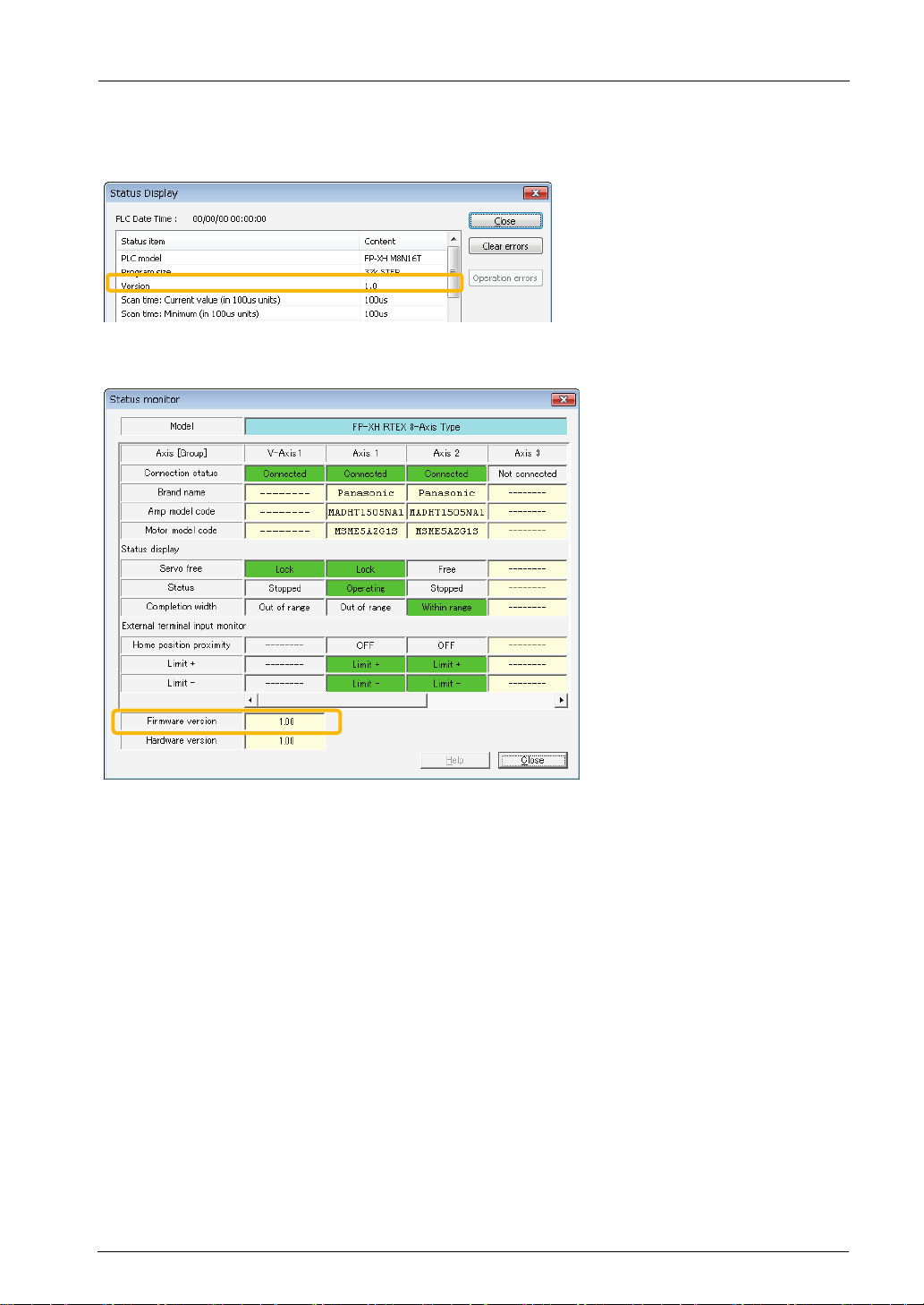
Table of Contents
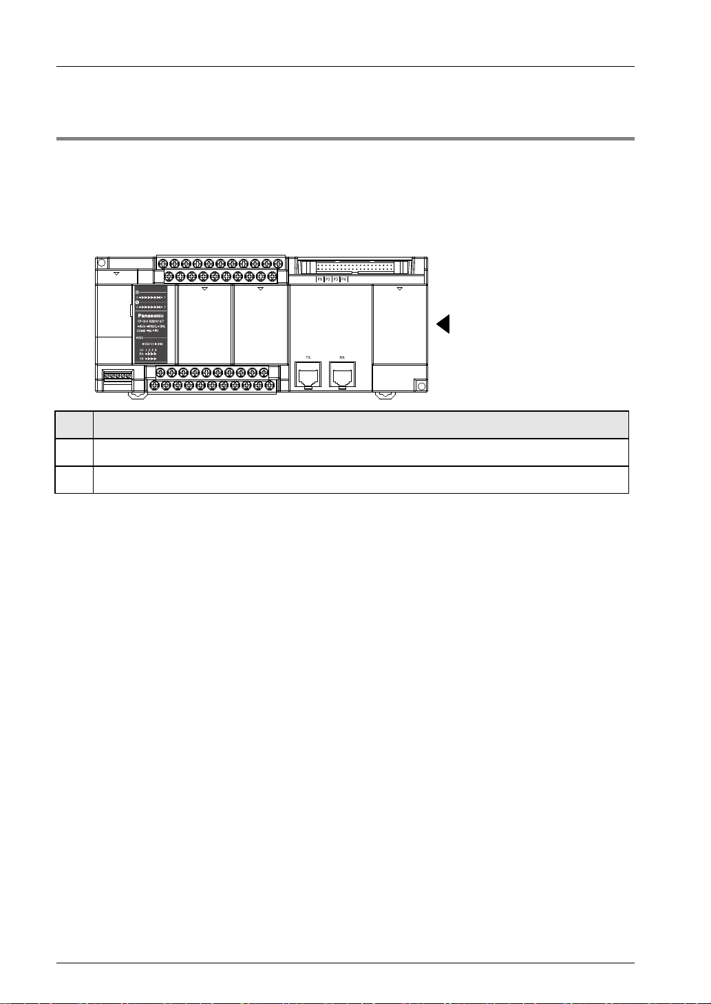
Confirmation based on the tool software
The version of the Main CPU can be confirmed according to Status Display of FPWIN GR7.
The version of Motion CPU can be confirmed via the Status Display dialog box of Configurator
PM7. The dialog box displays the "firmware version".
iii

Contents
Glossary
As for the following terms, similar expressions are used in the software, manuals and
specifications concerning FP-XH M8N Control Unit and Servo Amplifier A6N/A5N.
FP-XH M8N
Control Unit
-
RTEX generalpurpose input
-
A6N/A5N Description
Five inputs of symbols SI-MON1 to SI-MON5 are allocated on
the A6N/A5N side.
General-purpose
monitor input
-
RTEX operation
output
By default, the general-purpose monitor input (mark: SIMON1) is allocatd to the terminal on the servo amplifier side.
To read the general-purpose input (mark: SI-MON2), it is
necessary to change the parameter on the servo amplifier
side.
Up to two points (marks: SI-MON1 to SI-MON2) of the
general-purpose monitor inputs on the A6N/A5N side can be
read on the FP-XH M8N control Unit side. They are allocated
to the I/O input area (WX125).
On the A6N/A5N side, two outputs of marks EX-OUT1 and
EX-OUT2 are allocated.
By default, the RTEX operation output (mark: EX-OUT1) is
allocatd to the terminal on the servo amplifier side. To use the
RTEX operation output (mark: EX-OUT2), it is necessary to
change the parameter on the servo amplifier side.
RTEX generalpurpose output
General-purpose
output part
Motion control part -
Axis number Node number
-
-
On the FP-XH M8N Control Unit, the two "RTEX operation
outputs" connected to the A6N/A5N can be controlled with
user programs. The FP-XH M8N Control Unit side si allocated
to the I/O output area (WY125).
It indicatest the 8-point DC input circuits and 8-point transistor
output circuits connected to the terminal block of the FP-XH
M8N Control Unit.
It indicates the parts relating to the motor control, interface for
the RTEX network and pulse input interface in the FP-XH
M8N Control Unit.
The axis numbers controlled by the FP-XH M8N Control Unit
match the node numbers of the servo amplifier connected to
the RTEX network.
iv

Table of Contents
Table of Contents
1. System Structure ............................................................... 1-1
1.1 Overview of System .............................................................................. 1-2
1.1.1 Funcntions of Control Unit ....................................................................... 1-2
1.1.2 Outline of Specifications .......................................................................... 1-3
1.2 Unit List ................................................................................................. 1-4
1.2.1 FP-XH M8N Control Unit ......................................................................... 1-4
1.2.2 FP-X Expansion Unit ............................................................................... 1-4
1.2.3 FP-X Expansion FP0 Adapter ................................................................. 1-5
1.2.4 FP-X Add-on Cassette (Communication Cassette) ................................ 1-5
1.2.5 FP-X Add-on Cassette (Function Cassette) ............................................ 1-5
1.3 Unit Type and Product Number ............................................................. 1-6
1.3.1 FP-XH M8N16PD Control Unit ................................................................ 1-6
1.3.2 FP-X Expansion Unit ............................................................................... 1-6
1.3.3 FP-X Expansion FP0 Adapter ................................................................. 1-7
1.3.4 FP-X Add-on Cassette (Communication Cassette) ................................ 1-7
1.3.5 FP-X Add-on Cassette (Function Cassette) ............................................ 1-7
1.3.6 Options .................................................................................................... 1-7
1.3.7 Repair Parts ............................................................................................ 1-8
1.4 Restrictions on Unit Combinations ........................................................ 1-9
1.4.1 Restrictions on FP-X Expansion Units .................................................... 1-9
1.4.2 Restrictions on FP-X Expansion Adapter .............................................. 1-11
1.4.3 Restrictions on Add-on cassette Combination ...................................... 1-12
1.4.4 Restrictions on Communication Function ............................................. 1-14
1.5 Restrictions on Servo Amplifier ........................................................... 1-15
1.5.1 Restrictions on Parameter Settings ....................................................... 1-15
1.5.2 Combination of Parameters and Home Return Methods ...................... 1-16
v

Contents
2. Control Unit Specifications ............................................... 2-1
2.1 Parts Name and Funcations .................................................................. 2-2
2.1.1 Control Unit ............................................................................................. 2-2
2.1.2 Status Indicator LEDs .............................................................................. 2-4
2.1.3 COM0 Port Specifications ....................................................................... 2-5
2.2 Power Supply Specifications ................................................................. 2-6
2.3 Input / Output Specifications (General-purpose input/output part) .......... 2-7
2.3.1 Input Specifications ................................................................................. 2-7
2.3.2 Output Specifications .............................................................................. 2-8
2.4 Input Specifications (Pulse Input Part) ................................................... 2-9
3. I/O Allocation...................................................................... 3-1
3.1 Basic I/O Assignment ............................................................................ 3-2
3.1.1 Counting Method of I/O Numbers ........................................................... 3-2
3.1.2 I/O Number Assignment Method ............................................................. 3-2
3.2 List of I/O Numbers for Units ................................................................. 3-4
3.2.1 FP-XH M8N Control Unit (General-purpose I/O Part) ............................. 3-4
3.2.2 FP-XH M8N Control Unit (Motion Control Part) ...................................... 3-5
3.2.3 FP-X Expansion Unit ............................................................................... 3-7
3.2.4 FP-X Function Cassette .......................................................................... 3-8
3.3 Assignment of FP0 Expansion Units ...................................................... 3-9
3.3.1 I/O Number Assignment Method ............................................................. 3-9
3.3.2 Types and I/O Numbers of FP0R Expansion Units ............................... 3-10
3.3.3 Types and I/O Numbers of FP0 Expansion Units ................................. 3-11
3.4 Detailed I/O Information of Motion Control Part ................................... 3-12
vi

Table of Contents
4. Installation .......................................................................... 4-1
4.1 Installation ............................................................................................. 4-2
4.1.1 Installation Environment and Space........................................................ 4-2
4.2 Backup Battery Installation .................................................................... 4-4
4.2.1 Backup Battery Installation ...................................................................... 4-4
4.3 Add-on cassette Installation .................................................................. 4-5
4.3.1 Precautions for Installing Add-on cassettes ............................................ 4-5
4.3.2 Communications Cassette Installation .................................................... 4-5
4.3.3 Function Cassette Installation ................................................................. 4-6
4.4 Connecting FP-X Expansion Unit .......................................................... 4-7
4.4.1 Setup of Terminal Setting Switches ........................................................ 4-7
4.4.2 Confirmation of FP-X Expansion Cables ................................................ 4-7
4.4.3 Connecting FP-X expansion unit ............................................................. 4-8
4.5 Connecting FP0 Expansion Unit ........................................................... 4-9
4.5.1 Connecting FP0 Expansion Unit ............................................................. 4-9
4.5.2 Connecting FP-X Expansion FP0 Adapter ............................................ 4-10
4.6 Installation ........................................................................................... 4-11
4.6.1 Installation and Removal for DIN Rail ................................................... 4-11
4.6.2 Mounting with Screws ........................................................................... 4-12
5. Wiring of Power Supply and General-purpose I/O Parts . 5-1
5.1 Terminal Arrangement .......................................................................... 5-2
5.1.1 Power Supply and General-purpose I/O Parts ........................................ 5-2
5.2 Wiring of Power Supply ......................................................................... 5-3
5.2.1 General Precautions ............................................................................... 5-3
5.2.2 Grounding ................................................................................................ 5-3
5.2.3 Power Supply of Control Unit / Expansion Unit ....................................... 5-4
5.2.4 Power Supply of FP-X Expansion FP0 Adapter / FP0 Expansion Unit ... 5-6
vii

Contents
5.3 Wiring of Input and Output ..................................................................... 5-8
5.3.1 Precautions Regarding Input and Output Wirings ................................... 5-8
5.3.2 Input Wiring ............................................................................................. 5-9
5.3.3 Output Wiring ........................................................................................ 5-11
5.4 Wiring of Terminal Block ...................................................................... 5-12
5.4.1 Suitable Wires ....................................................................................... 5-12
5.4.2 Terminal Block Cover ............................................................................ 5-12
5.4.3 Installation and Removal of Terminal Block .......................................... 5-13
5.5 Safety Measures ................................................................................. 5-14
5.5.1 Safety Measures ................................................................................... 5-14
5.5.2 Momentary Power Failures ................................................................... 5-15
5.5.3 Watchdog Timer .................................................................................... 5-15
6. Wiring of Motion I/O Parts ................................................. 6-1
6.1 Terminal Layout Diagram ...................................................................... 6-2
6.2 Settings on Servo Amplifier ................................................................... 6-3
6.2.1 Checking Rotary Switches ...................................................................... 6-3
6.2.2 Connection of Limit Input and Near Home Input ..................................... 6-4
6.2.3 Combination of Parameters and Home Return Methods ........................ 6-5
6.2.4 Connection of General-purpose Monitor Input ........................................ 6-6
6.2.5 Connection of RTEX Operation Output ................................................... 6-6
6.3 Connection of Network .......................................................................... 6-7
6.3.1 Wiring Method ......................................................................................... 6-7
6.3.2 Precautions on Wiring ............................................................................. 6-7
6.4 Pulse Input Connection ......................................................................... 6-8
6.4.1 Linear Driver Type ................................................................................... 6-8
6.4.2 Transistor Open-collector Type ............................................................... 6-8
6.4.3 Transistor Resistor Pulling Up Type ........................................................ 6-8
6.4.4 Precautions on Wiring ........................................................................... 6-10
6.4.5 Specifications of Scattered Cable Connectors ...................................... 6-10
viii
6.4.6 Usage of Scattered Cable Connector ................................................... 6-11

Table of Contents
7. Power On/Off and Check Items ......................................... 7-1
7.1 Before Turning On the Power ................................................................ 7-2
7.2 Procedure for Turning On the Power ..................................................... 7-3
7.2.1 Procedure for Turning On the Power ...................................................... 7-3
7.2.2 Procedure for Turning Off the Power ...................................................... 7-3
7.3 Check with Power Turned On ............................................................... 7-4
7.3.1 Check items after turning power on ........................................................ 7-4
7.3.2 Checking the network communication state ........................................... 7-5
7.3.3 Checking the safety circuit based on a unit ............................................ 7-6
7.3.4 Checking the operation of near home switch .......................................... 7-7
7.3.5 Checking the rotation, movement direction and distance ....................... 7-7
8. Steps Before Running ........................................................ 8-1
8.1 Before Turning on the Power ................................................................ 8-2
8.1.1 Check Items ............................................................................................ 8-2
8.1.2 Steps Before Running ............................................................................. 8-3
8.2 Offline Editing of the Program ............................................................... 8-4
8.2.1 Program Elements................................................................................... 8-4
8.2.2 Settings of the System Register .............................................................. 8-4
8.2.3 Setting of Position Control Parameters ................................................... 8-5
8.3 Program Download and Run ................................................................. 8-6
8.3.1 Before Turning on the Power .................................................................. 8-6
8.3.2 Program Downloading and Mode Switching ........................................... 8-7
8.3.3 Overall Program Check ......................................................................... 8-11
8.3.4 Program Verify ...................................................................................... 8-11
8.4 Online Editing ..................................................................................... 8-13
8.4.1 Online Editing Summary ...................................................................... 8-13
8.4.2 Online Editing of the Program ............................................................... 8-13
8.4.3 Online Editing of the System Register .................................................. 8-15
ix

Contents
8.5 Program block ..................................................................................... 8-16
8.5.1 Program block summary ....................................................................... 8-16
8.5.2 Change Sequence of PBs ..................................................................... 8-17
9. Setting of Position Control Parameters ........................... 9-1
9.1 Axis Allocation for Use ........................................................................... 9-2
9.1.1 Settings in Configurator PM7 .................................................................. 9-2
9.2 Parameter settings ................................................................................ 9-4
9.2.1 Parameter Settings in Configurator PM7 ................................................ 9-4
9.2.2 Parameter setting items .......................................................................... 9-5
9.3 Synchronous Parameter / Cam Pattern Settings ................................... 9-8
9.3.1 Synchronization parameter settings ........................................................ 9-8
9.3.2 Cam Pattern Settings .............................................................................. 9-9
9.4 Creating Positioning Data Table .......................................................... 9-10
9.4.1 Structure of the position control data table ............................................ 9-10
9.4.2 Select type of position control data setting area ................................... 9-11
9.4.3 Data table No. and position control startup ........................................... 9-12
9.4.4 Running Mode and Data table .............................................................. 9-13
9.5 Saving and Managing Files ................................................................. 9-14
9.5.1 File Type ................................................................................................ 9-14
9.5.2 Saving Parameters as Part of Project File ............................................ 9-14
9.5.3 Saving Parameters as Parameter File .................................................. 9-15
9.5.4 Exporting Parameters to CSV Files ...................................................... 9-16
10. Transfer to Unit and Commissioning............................. 10-1
10.1 Check on Settings ............................................................................... 10-2
10.1.1 Data Check of Parameters .................................................................... 10-2
10.1.2 Comparison of Parameter information .................................................. 10-3
10.2 Transfer of parameters ........................................................................ 10-4
x

Table of Contents
10.2.1 Download by FPWN GR7 ..................................................................... 10-4
10.2.2 Download by Configurator PM7 ............................................................ 10-5
10.3 Monitoring on Configurator PM7 ......................................................... 10-6
10.3.1 Status Monitor ....................................................................................... 10-6
10.3.2 Data Monitor .......................................................................................... 10-8
10.4 Tool Operation .................................................................................. 10-10
10.4.1 Tool Operation Function ...................................................................... 10-10
10.4.2 Servo ON/OFF with Tool Operation Function ..................................... 10-11
10.4.3 JOG Operation with Tool Operation Function ..................................... 10-12
10.4.4 Home Return by Tool Operation Function .......................................... 10-14
10.4.5 Positioning by Tool Operation Function .............................................. 10-16
10.4.6 Teaching by Tool Operation Function ................................................. 10-19
10.5 Monitoring Current Value with Program............................................. 10-21
10.5.1 Current Value Area.............................................................................. 10-21
10.5.2 Reading of the current value ............................................................... 10-21
11. Automatic Operation (Position Control) ........................ 11-1
11.1 Basic Operations ................................................................................. 11-2
11.1.1 Position Control Method ........................................................................ 11-2
11.1.2 Setting and Operation of E-point Control .............................................. 11-4
11.1.3 Setting and Operation of P-point Control .............................................. 11-5
11.1.4 Setting and Operation of C-point Control .............................................. 11-6
11.1.5 Setting and Operation of J-point Control ............................................... 11-7
11.1.6 Sample Program (E-point, P-point and C-point Control)....................... 11-9
11.1.7 Sample Program (J-point Control) ...................................................... 11-10
11.1.8 Programming Precautions ................................................................... 11-11
11.2 Interpolation Control .......................................................................... 11-12
11.2.1 Interpolation Control Types ................................................................. 11-12
11.2.2 Setting and Operation of 2-axis Linear Interpolation........................... 11-15
11.2.3 Setting and Operation of 2-axis Circular Interpolation ........................ 11-17
11.2.4 Setting and Operation of 3-axis Linear Interpolation........................... 11-19
xi

Contents
11.2.5 Setting and Operation of 3-axis Spiral Interpolation ........................... 11-21
11.2.6 Sample Program (Interpolation Control) ............................................. 11-23
11.3 Positioning Repeat Function .............................................................. 11-24
11.3.1 Setting and Operation of Repeat Operation ........................................ 11-27
12. Automatic Operation (Synchronous Control) ............... 12-1
12.1 Synchronous Control ........................................................................... 12-2
12.1.1 Outline of Synchronous Control ............................................................ 12-2
12.2 Settings for Master and Slave Axes ..................................................... 12-4
12.2.1 Selection for Master and Slave Axes .................................................... 12-4
12.2.2 Selection of Slave Axes and Settings ................................................... 12-5
12.3 Start and Cancel of Synchronous Control ............................................ 12-6
12.3.1 Start and Cancel of Synchronous Control ............................................. 12-6
12.3.2 Precautions When Canceling or Starting Synchronous Control ........... 12-8
12.4 Electronic Gear Function ................................................................... 12-12
12.4.1 Outline of Electronic Gear Function .................................................... 12-12
12.4.2 Types and Contents of Setting Parameters ........................................ 12-13
12.4.3 Gear Ratio Changes while in Operation .............................................. 12-14
12.5 Electronic Clutch Function ................................................................. 12-16
12.5.1 Electronic Clutch Function................................................................... 12-16
12.5.2 Types and Contents of Setting Parameters ........................................ 12-17
12.5.3 Trigger Types for Electronic Clutch ..................................................... 12-18
12.5.4 Engagement Methods of Electronic Clutch ......................................... 12-19
12.5.5 Phase Specification Clutch Off Function ............................................. 12-20
12.6 Electronic Cam Function .................................................................... 12-22
12.6.1 Outline of Electronic Cam Function ..................................................... 12-22
12.6.2 Types and Contents of Setting Parameters ........................................ 12-24
12.6.3 Cam Pattern Setting Method ............................................................... 12-25
xii
12.6.4 Rewriting Cam Patterns by Programs ................................................. 12-32
12.6.5 Advance Angle Correction Function .................................................... 12-39

Table of Contents
13. Manual Operation (JOG Operation) ............................... 13-1
13.1 Setting and Operation of JOG Operation ............................................. 13-2
13.2 Speed Change During Operation ........................................................ 13-4
14. Manual Operation (Home Return) ................................... 14-1
14.1 Type of Home Return .......................................................................... 14-2
14.2 Setting and Operaion of Home Return ................................................ 14-6
15. Pulse Input Function ....................................................... 15-1
15.1 Pulse Input .......................................................................................... 15-2
15.1.1 Pulse input application .......................................................................... 15-2
15.1.2 Selection of Pulse Input Applications .................................................... 15-3
15.1.3 Input mode of pulse input ...................................................................... 15-4
15.1.4 Monitoring of Pulse Input Values .......................................................... 15-6
15.1.5 Pulse Input Value Change Function...................................................... 15-6
15.2 Setting and Operation of Pulsar .......................................................... 15-8
15.2.1 Overview ............................................................................................... 15-8
15.2.2 Settings for Pulsar Operation ................................................................ 15-9
15.2.3 Operation of Pulsar ............................................................................. 15-10
15.3 Pulse Input / High-speed Counter Function ....................................... 15-12
15.3.1 Overview ............................................................................................. 15-12
15.3.2 Settings When Using High-speed Counter ......................................... 15-12
15.3.3 Count Disable/Enable Control ............................................................. 15-13
16. Stop Function .................................................................. 16-1
16.1 Types and Settings of Stop Function ................................................... 16-2
16.1.1 Type of Stop Operations ....................................................................... 16-2
xiii

Contents
16.1.2 Stop Tme Settings ................................................................................. 16-3
16.2 Operation During Stop ......................................................................... 16-4
16.3 Pause Function ................................................................................... 16-5
16.3.1 Pause Function ..................................................................................... 16-5
16.3.2 Pause Settings ...................................................................................... 16-5
17. Auxiliary Function ........................................................... 17-1
17.1 Dwell Time........................................................................................... 17-2
17.2 Software Limit ...................................................................................... 17-3
17.3 Auxiliary Output ................................................................................... 17-4
17.3.1 Auxiliary Output Function ...................................................................... 17-4
17.3.2 Auxiliary Output Settings ....................................................................... 17-5
17.3.3 Monitoring of Auxiliary Output ............................................................... 17-6
17.3.4 Operation upon Movement Change during Operation .......................... 17-6
17.4 Coordinate Origin ................................................................................ 17-7
17.5 Current Value Update .......................................................................... 17-9
17.6 Target Speed Change Function ......................................................... 17-11
17.6.1 Overview.............................................................................................. 17-11
17.6.2 Setting Procedures and Operations (Speed Direct Specification Method)17-12
17.6.3 Setting Procedures and Operations (Ratio Specification Method)...... 17-15
17.7 Movement Amount Change Function................................................. 17-17
17.7.1 Overview.............................................................................................. 17-17
17.7.2 Setting Procedures and Operations .................................................... 17-18
17.8 Direct Input / Output .......................................................................... 17-22
17.8.1 Direct Input / Output Function ............................................................. 17-22
17.8.2 Direct Input .......................................................................................... 17-24
17.8.3 Direct Output ....................................................................................... 17-25
17.9 Torque Limit ...................................................................................... 17-26
xiv

Table of Contents
17.10 Monitor Error (Torque / Actual Speed Judgement) ............................ 17-29
17.11 Operation Done Signal ...................................................................... 17-30
17.11.1 Operation Done Flag and Imposition Flag ...................................... 17-30
17.12 Position Deviation Simple Monitor ..................................................... 17-31
17.13 AMP Parameter R/W Function .......................................................... 17-32
17.13.1 Overview.......................................................................................... 17-32
17.13.2 Reading Parameters from AMP ...................................................... 17-33
17.13.3 Writing Parameters to AMP ............................................................. 17-35
17.13.4 Saving AMP Parameters (Writing to EEPROM).............................. 17-37
17.13.5 Resetting AMP (Restart) ................................................................. 17-39
17.14 AMP Monitoring Function .................................................................. 17-41
17.14.1 Overview.......................................................................................... 17-41
17.14.2 Monitoring Items .............................................................................. 17-41
17.14.3 Monitoring Procedure ...................................................................... 17-43
18. Instruction Reference ...................................................... 18-1
18.1 Motion Control Instructions.................................................................. 18-2
18.1.1 [F384 PTBLR] Positioning parameter read instruction.......................... 18-2
18.1.2 [F385 PTBLW] Positioning parameter write instruction ........................ 18-3
18.1.3 [F386 PSET] Positioning start data table setting .................................. 18-4
18.1.4 [F387 PSTRD] Axis status acquisition .................................................. 18-5
18.1.5 [F388 PERRD] Positioning error /warning acquisition .......................... 18-7
18.1.6 [F389 UCLR] Positioning error / warning clearing ................................. 18-8
18.2 Direct Input Instruction ........................................................................ 18-9
18.2.1 [DST·DST/] Direct start / Direct start NOT ............................................ 18-9
18.2.2 [DAN·DAN/] Direct AND /·Direct AND NOT ................................... 18-12
18.2.3 [DOR·DOR/] Direct OR / Direct OR NOT ....................................... 18-15
18.3 Direct Output Instruction ................................................................... 18-18
18.3.1 [DOT] Direct output ........................................................................ 18-18
18.3.2 [DSET·DRST ] Direct set / Direct reset ........................................... 18-21
xv

Contents
18.3.3 [DKP] Direct hold ............................................................................ 18-26
19. Error/Warning Annunciation Function .......................... 19-1
19.1 Errors and Warnings ............................................................................ 19-2
19.1.1 Errors and Warnings ............................................................................. 19-2
19.1.2 Check and Clearing with Configurator PM7 .......................................... 19-2
19.1.3 Check and Clearing with User Program ................................................ 19-3
19.1.4 Error/Warning Log ................................................................................. 19-4
19.2 Change of Error Recovery Processing ................................................. 19-6
19.2.1 Outline ................................................................................................... 19-6
19.3 Table of Error Codes ........................................................................... 19-7
19.3.1 AMP Errors (0001H 0- ) ......................................................................... 19-7
19.3.2 System Errors (1000H - ) .................................................................... 19-14
19.3.3 AMP Communication Errors (2000H - ) .............................................. 19-15
19.3.4 Axis Operation Errors (3000H - ) ......................................................... 19-16
19.3.5 Set Value Errors (4000H - ) ................................................................. 19-18
19.3.6 Setting value errors of synchronous parameters (5000H - ) ............... 19-22
19.4 Table of Warning Codes .................................................................... 19-25
19.4.1 AMP Warnings (A000H - ) ................................................................... 19-25
19.4.2 Unit Warning (B000H - ) ...................................................................... 19-26
20. Troubleshooting .............................................................. 20-1
20.1 Self-diagnosis Function ....................................................................... 20-2
20.1.1 Status display LED of the Control Unit .................................................. 20-2
20.1.2 Status Display LED of the FP-X Expansion FP0 Adapter ..................... 20-3
20.1.3 Operation mode in case of exception .................................................... 20-3
20.2 What to Do If an Error Occurs.............................................................. 20-4
20.2.1 ERR LED Blinking ................................................................................. 20-4
xvi
20.2.2 When Not Switched to RUN Mode ........................................................ 20-6
20.2.3 When ERR.LED Lights Up .................................................................... 20-6

Table of Contents
20.2.4 If All LEDs are Not Lit ............................................................................ 20-7
20.2.5 When Protection Error Message Shows ............................................... 20-7
20.2.6 When the Output is Not Normal ............................................................ 20-8
20.2.7 When Expansion Units are Not Operated ............................................. 20-9
20.2.8 In Case of Communication Error (RS-232C) ...................................... 20-10
20.2.9 In Case of Communication Error (RS-422) ......................................... 20-11
20.2.10 In Case of Communication Error (RS-484) ..................................... 20-12
20.2.11 In Case of Communication Error (Ethernet) .................................... 20-13
20.3 What to Do If an Error Occurs ........................................................... 20-14
20.3.1 Cannot Communicate with AMP ......................................................... 20-14
20.3.2 Motor does Not Rotate and Operate ................................................... 20-15
21. Memory /Master Memory Cassette ................................. 21-1
21.1 Memory Backup .................................................................................. 21-2
21.1.1 Program Memory Backup ..................................................................... 21-2
21.1.2 Operation Memory Backup ................................................................... 21-2
21.1.3 Operation Memory Backup (When Battery Installed) ............................ 21-3
21.1.4 Alarm Battery Error / Setting of the Hold area ...................................... 21-4
21.2 RAM / ROM Transfer Function ............................................................ 21-6
21.2.1 Outline of function ................................................................................. 21-6
21.2.2 Operations Using Tool Software ........................................................... 21-6
21.3 Functions of Master Memory Cassette ................................................ 21-7
21.3.1 Outline of Functions .............................................................................. 21-7
21.3.2 Setting of Master Memory Unit .............................................................. 21-7
21.4 Master Memory Function .................................................................... 21-8
21.4.1 Outline of Function ................................................................................ 21-8
21.4.2 Before Turning on the Power ................................................................ 21-9
21.4.3 Transferring Data to Master Memory Cassette ................................... 21-10
21.4.4 Transferring Data from Master Memory Cassette to Control Unit ...... 21-12
21.4.5 Using Master Memory Cassette with Other Models ............................ 21-13
21.5 Clock/Calendar ................................................................................. 21-14
xvii

Contents
21.5.1 Outline of Function .............................................................................. 21-14
21.5.2 Clock/calendar Setting ........................................................................ 21-14
21.5.3 Clock/calendar Application Examples ................................................. 21-15
22. Security Functions .......................................................... 22-1
22.1 Password Protection Function ............................................................. 22-2
22.1.1 Outline of Function ................................................................................ 22-2
22.1.2 Tool software setting ............................................................................. 22-2
22.2 Program Upload Protection Function ................................................... 22-9
22.2.1 Outline of Function ................................................................................ 22-9
22.2.2 Tool Software Setting .......................................................................... 22-10
22.3 Security Function Applicability List ..................................................... 22-11
22.3.1 Control Unit ......................................................................................... 22-11
23. General-purpose Input / High-speed counter Function 23-1
23.1 General-purpose Input / High-speed counter Function Summary ........ 23-2
23.1.1 High-speed counter Function Summary ................................................ 23-2
23.1.2 Counting Range and Elapsed Value (Current Value) Area ................... 23-2
23.1.3 When using the high-speed counter function ........................................ 23-3
23.1.4 Type of Input Mode ............................................................................... 23-4
23.1.5 Minimum Input Pulse Width................................................................... 23-5
23.2 Settings of the System Registers ......................................................... 23-6
23.2.1 Settings of System Registers ................................................................ 23-6
23.3 General-purpose Input / High-speed Counter Related Instruction ........ 23-8
23.3.1 [F0 MV] High-speed counter control instruction .................................... 23-8
23.3.2 [F1 DMV] Elapsed value read and write instruction ............................ 23-10
23.3.3 [F166 HC1S] High-speed counter target value consistent ON instruction
[F167 HC1R] High-speed counter target value consistent OFF instruction23-11
23.3.4 Interruption program startup when target value has consistent control23-13
23.4 Sample Program ............................................................................... 23-14
xviii

Table of Contents
23.4.1 Running of the position control which has used inverter (1 speed) .... 23-14
23.4.2 Running of the position control which has used inverter (2 speed) .... 23-16
24. Other Functions ............................................................... 24-1
24.1 Analog Potentiometer.......................................................................... 24-2
24.1.1 Outline of Function ................................................................................ 24-2
24.1.2 Analog Potentiometer Application Examples ........................................ 24-2
24.2 Input Time Constant Setting Function ................................................. 24-3
24.2.1 Outline of Function ................................................................................ 24-3
25. Maintenance and Inspection ........................................... 25-1
25.1 Precautions for Using Backup Battery ................................................. 25-2
25.1.1 Backup Battery Replacement ................................................................ 25-2
25.1.2 Backup Battery Lifetime and Replacement Time .................................. 25-3
25.2 Inspection ........................................................................................... 25-4
26. Specifications .................................................................. 26-1
26.1 Control Unit Specifications .................................................................. 26-2
26.1.1 General Specifications .......................................................................... 26-2
26.1.2 Performance Specifications .................................................................. 26-3
26.1.3 Performance Specifications of Motion Control Part .............................. 26-5
26.2 Communication Specifications ............................................................ 26-8
26.2.1 Communication Specifications of Control Unit ...................................... 26-8
26.2.2 Specifications of Communication Cassette ........................................... 26-9
26.3 Operation Memory Areas .................................................................. 26-11
26.4 Positioning Memory .......................................................................... 26-12
26.4.1 Entire Configuration of Positioning Memory ........................................ 26-12
26.4.2 Common Area (Memory Area No.0) ................................................... 26-16
xix

Contents
26.4.3 Each Axis Information Area (Memory Area No. 1) .............................. 26-34
26.4.4 Each Axis Setting Area (Memory Area No. 2) ..................................... 26-36
26.4.5 Cam Pattern Editing Area (Memory Area No. 3) ................................. 26-50
26.4.6 Synchronous Control Area (Memory Area No. 4) ............................... 26-54
26.4.7 Positioning Operation Change Setting Area (Memory Area No. 5) .... 26-57
26.4.8 AMP Parameter Control Area (Memory Area No. 6) ........................... 26-58
26.5 Table of System Registers ................................................................. 26-59
26.6 Table of Special Internal Relays ........................................................ 26-65
26.7 Table of Special Data Registers ........................................................ 26-78
26.8 Table of Error Codes ......................................................................... 26-91
26.8.1 Table of Syntax Check Errors ............................................................. 26-91
26.8.2 Table of Self-diagnostic Errors ............................................................ 26-92
26.8.3 Table of MEWTOCOL-COM Communication Errors .......................... 26-94
26.9 Dimensions........................................................................................ 26-95
26.9.1 Dimensions .......................................................................................... 26-95
26.9.2 Installation Dimensions ....................................................................... 26-95
xx

1
System Structure
System Structure
FP-XH
M8N
X2A X2A X2A
A6N
A5N
RX RXRX
X2B
X2B
X2B
TX
TX
TX
1.1 Overview of System
1.1.1 Funcntions of Control Unit
Conrols the Servo Motor MINAS A6N/A5N series
The FP-XH M8N Control Unit can control servo motors of up to 8 axes via the motiondedicated network Realtime Express (RTEX). It achieves wiring saving by network connection
and high-speed control.
(Note): Realtime Express and RTEX are registered trademarks of Panasonic.
Frexibly deals with positioning control up to eight axes
The FP-XH M8N Control Unit supports independent control, interpolation control and
synchronous control, and deals with simple control through complicated control.
Hybrid controller equipped with genera-purpose inputs and outputs
The general-purpose I/O of 8-point inputs and 8-point outputs and RS-232C port are equipped
as the standard equipment in addition to the I/F for network servo.
Pulse input function usable for high-speed counter and manual pulsar
A maximum of four-channel inputs are available, and can be used for the high-speed counter
and pulsar operation.
Can use various options of the existing models of FP-X series
Various add-on cassettes and expansion units can be used. The communication interface,
digital I/O and analog I/O can be easily expanded.
Shortens the startup time by using "Configurator PM7"
By using the setting monitoring software for positioning control "Configurator PM7",
positioning parameters and tables can be easily managed. Also, the "Tool operation function"
which enables the adjustment without ladder programs shortens the startup time.
1-2

1.1 Overview of System
1.1.2 Outline of Specifications
The unit supports the independent control, interpolation control and synchronous control, and
the maximum of 8 axes can be used within the following ranges.
Combination of control axes
Item name Specifications
Number of axes
controlled
Independent
control
Interpolation
Control
Synchronous
control
(Note 1): The pulse input can be used as the input of the synchronous control master axis.
Communication specifications of motion control part
Item Specification
Physical layer
Baud rate 100 Mbps
Trasmission distance Between nodes: Max. 100 m, Total length: Max. 200 m
Topology Ring
Applicable cable STP cable (category 5e or higher)
Connector 9-pin RJ45 x 2
Communication cycle 0.5 ms
Position command update 1 ms
No. of connected slaves Max. 8 slaves
Coonnected slave Panasonic AC Servo Motor A6N series/A5N series
Max. 8 axes
Max. 8 axes
2-axis linear interpolation, 2-axis circular interpolation, 3-axis linear
interpolation, 3-axis spiral interpolation: max. 8 axes
Master axis (real axis): Max. 4
axes
Master axis (virtual axis): Max.
2 axes
Slave axis: Max. 8 axes
100BASE-TX (IEEE802.3)
Combination of real
and virtual axes: Max.
4 axes
Combination
of master and
slave axes:
Max. 8 axes
Combination
of
independent,
interpolation
and
synchronous
controls:
Max. 8 axes
1-3
System Structure
1.2 Unit List
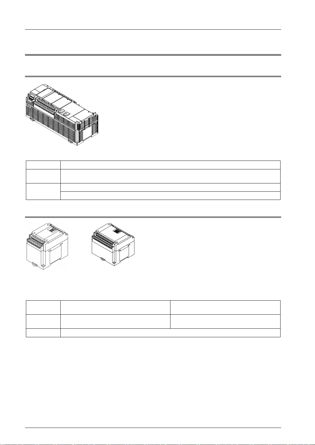
1.2.1 FP-XH M8N Control Unit
Divided into the following types according to points, power supply and output type.
Points General I/O part: 16 points, motion control part (RTEX I/F and 4-ch pulse input for 8-axis control)
Power
supply
Output
24 VDC
General output part: transistor (PNP output)
RTEX I/F port for motion control RX45 x 2 ports (RX/TX)
1.2.2 FP-X Expansion Unit
Divided into the following types according to points, power supply and output type. Can be
used with the old models FP-X.
FP-X Expansion Unit
Points
Power
supply
Output Relay or transistor (NPN output or PNP output)
14 points (for output) / 16 points (for input) / 16
points
No power supply 100-240 VAC or 24 VDC
30 points
1-4
1.2 Unit List
1.2.3 FP-X Expansion FP0 Adapter
Interface adapters enabling connection with FP0/FP0R series expansion unit / high function
unit.
1.2.4 FP-X Add-on Cassette (Communication Cassette)
Divided into the following types according to the type of communication interface and the
number of channels.
RS-232C (5-wire) × 1ch
RS-232C (3-wire) × 2ch
Communication pattern
RS-485 / RS-422 × 1ch
RS-485 × 1ch + RS-232C (3-wire) × 1ch
RS-485 × 2ch
Ethernet × 1ch + RS-232C (3-wire) × 1ch
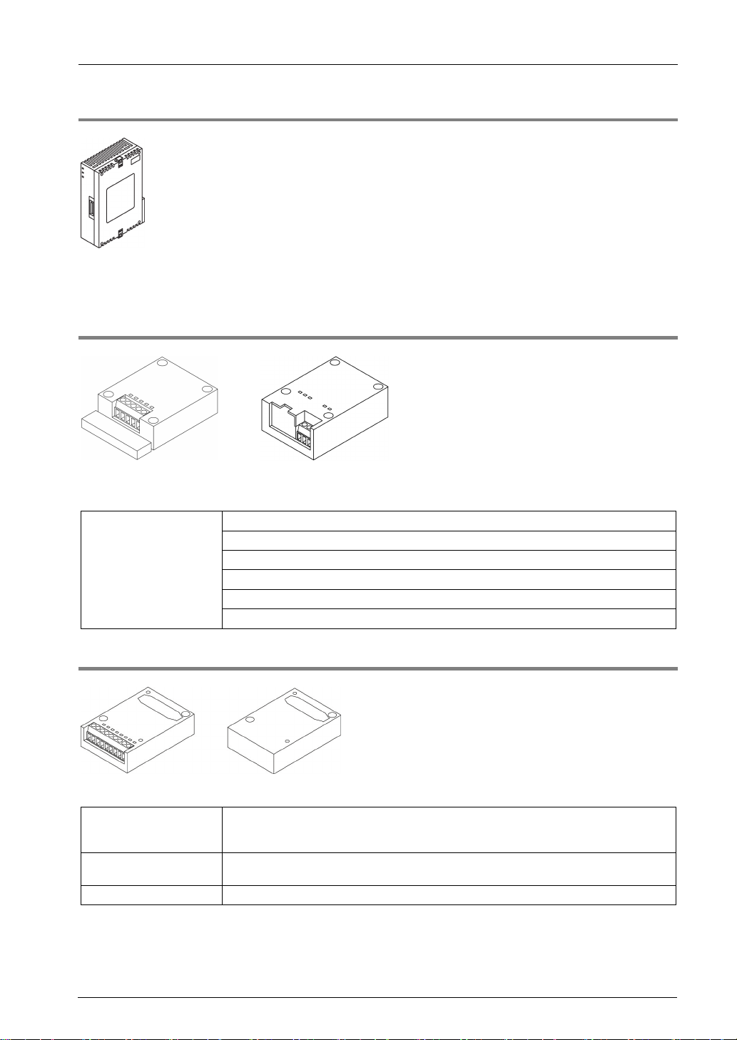
1.2.5 FP-X Add-on Cassette (Function Cassette)
Divided into the following types according to the output type and function.
Analog input and output
Digital input and output
Master memory Master memory + real-time clock
Analog input × 2ch
Analog output × 2ch
Analog input × 2ch + analog output × 1ch
Input 8 points, transistor output 8 points
Input 4 points + transistor output 3 points
1-5

System Structure
Input / Output Specifications
Power supply
Input / Output Specifications
Power supply
1.3 Unit Type and Product Number
1.3.1 FP-XH M8N16PD Control Unit
Product Name
FP-XH M8N16PD
Control Unit
DC input 8 points, transistor output 8 points
RTEX I/F (for 8 axes) for motion control
4-channel pulse input
1.3.2 FP-X Expansion Unit
Product Name
DC input 8 points, relay output 8 points - AFPX-E16R
FP-X E16
expansion I/O unit
FP-X E30
expansion I/O unit
FP-X E16
expansion input unit
FP-X E14R
expansion output unit
(Note) Comes with expansion cables (8 cm type).
DC input 8 points, transistor output (NPN) 8
points
DC input 8 points, transistor output (PNP) 8
points
DC input 16 points, relay output 14 points
DC input 16 points, transistor output (NPN)
14 points
DC input 16 points, transistor output (PNP)
14 points
DC input 16 points - AFPX-E16X
Relay output 14 points - AFPX-E14YR
Specification
Specification
Product no.
24 VDC AFPXHM8N16PD
Product no.
- AFPX-E16T
- AFPX-E16P
100-240 VAC AFPX-E30R
24 VDC AFPX-E30RD
100-240 VAC AFPX-E30T
24 VDC AFPX-E30TD
100-240 VAC AFPX-E30P
24 VDC AFPX-E30PD
1-6

1.3 Unit Type and Product Number
Name
Specification
Product no.
1.3.3 FP-X Expansion FP0 Adapter
Name Specification Product no.
FP-X Expansion FP0
Adapter
(Note) Comes with expansion cables (8 cm type).
Used to connect with the FP0 expansion unit AFPX-EFP0
1.3.4 FP-X Add-on Cassette (Communication Cassette)
Name Specification Product no.
RS-232C 5-wire × 1 channel AFPX-COM1
RS-232C 3-wire × 2 channel AFPX-COM2
FP-X communication
cassette
RS-485 / RS-422 (insulated) × 1 channel AFPX-COM3
RS-485 (insulated) × 1 channel + RS-232C 3-wire × 1 channel AFPX-COM4
RS-485 (insulated) × 2 channels (non-insulated between
channels)
Ethernet port + RS-232C 3-wire × 1 channel AFPX-COM5
1.3.5 FP-X Add-on Cassette (Function Cassette)
AFPX-COM6
Name Specification Product no.
FP-X analog input
cassette
FP-X analog output
cassette
Analog
input and
output
Digit
input and
output
FP-X master memory cassette Master memory + real-time clock AFPX-MRTC
FP-X analog I/O cassette
FP-X thermocouple
cassette
FP-X temperature
measuring resistor
cassette
FP-X input cassette 8-point DC input AFPX-IN8
FP-X output cassette 8-point transistor output (NPN) AFPX-TR8
FP-X output cassette 6-point transistor output (PNP) AFPX-TR6P
FP-X input and output
cassette
Analog input (non-isolated) × 2 channels AFPX-AD2
Analog output (insulated) × 2 channels
(insulated between channels)
Analog input (insulated) × 2 channels
(non-insulated between channels)
+ analog output (insulated) × 1 channel
Thermocouple input (insulated) × 2 channels
(insulated between channels)
Temperature measuring resistor input
(insulated) × 2 channels
(insulated between channels)
4-point DC input + 3-point transistor output
(NPN)
AFPX-DA2
AFPX-A21
AFPX-TC2
AFPX-RTD2
AFPX-IN4T3
1.3.6 Options
FP-XH backup battery
Required when expanding operation memory keeping area and
using the clock/calendar function.
AFPXHBATT
1-7

System Structure
1.3.7 Repair Parts
Name Specification Product no.
FP-X expansion
cable (note)
8cm AFPX-EC08
30cm AFPX-EC30
80cm AFPX-EC80
FP0
power cable
(Note 1): The FP-X expansion unit and high-function unit include 8 cm expansion cables. The total length of the
expansion cables should be within 160 cm.
(Note 2): when using long expansion cables, I/O checking error may occur due to noises and other effects. In this
case, it is recommended to take measures such as using ferrite cores.
For expansion FP0 adapters, 1 m long AFP0581
1-8
 Loading...