

Page 1

Programmable Controller
FP-XH Series
User’s Manual
Basic
Western version
WUME-FPXHBASG-01
2020.10
panasonic.net/id/pidsx
Page 2

(MEMO)
2 WUME-FPXHBASG-01
Page 3

Introduction
Thank you for purchasing a Panasonic product. Before you use the product, please carefully
read through the user’s manual, and understand it in detail to use the product properly.
Types of Manuals
● The following user’s manuals are available for the FP-XH series. Please refer to a relevant
manual for the unit and purpose of your use.
● The manuals can be downloaded from our Download Center:https://
industrial.panasonic.com/ac/e/dl_center/.
Unit name or purpose of
use
FP-XH Control Unit
Positioning Function /
PWM Output / High-speed
Counter Function
Communication Functions
FP-X Extension
(Communication) Cassette
FP-X Expansion Unit
FP-X Function Cassettes
Manual name Manual code
FP-XH User‘s Manual (Basic) WUME-FPXHBASG
FP Series Programming Manual ARCT1F313E
FP-XH User’s Manual
(Positioning / PWM Output / High-speed Counter)
FP-XH User‘s Manual (COM Communication) WUME-FPXHCOMG
FP-X Series User’s Manual WUME-FPX
WUME-FPXHPOSG
WUME-FPXHBASG-01 iii
Page 4
SAFETY PRECAUTIONS
● To prevent accidents or personal injuries, please be sure to comply with the following items.
● Prior to installation, operation, maintenance and inspection, please read this manual carefully for proper use.
● Before using the product, please fully understand the knowledge related to the equipment, safety
precautions and all other precautions.
● Safety precautions are divided into two levels in this manual: Warning and Caution.
Incorrect operation may lead to death or serious injury.
● Take appropriate safety measures for the external circuit of the product to ensure the security of the whole
system in case of abnormalities caused by product failure or external factors.
● Do not use this product in areas with inflammable gases.
Otherwise it may lead to an explosion.
● Do not put this product into a fire.
Otherwise it may cause damage to the battery or other electronic parts.
● Do not impact, charge or heat the lithium battery, and do not put it into a fire.
Otherwise it may lead to fire or damage.
Incorrect operation may lead to injury or material loss.
● To prevent the excessive exothermic heat or smoke generation of the product, a certain margin is required
for guaranteed characteristics and performance ratings of relative products.
● Do not disassemble or modify the product.
Otherwise it may lead to the excessive exothermic heat or smoke generation of the product.
● Do not touch terminal blocks during power-on.
Otherwise it may result in an electric shock.
● Create an emergency stop and interlock circuit in the external devices.
● Connect wires and connectors reliably.
Otherwise it may lead to the excessive exothermic heat or smoke generation of the product.
● Do not carry out construction (wiring, removal, etc.) during power-on.
Otherwise it may result in an electric shock.
● If the equipment is used in a manner not specified by the Panasonic, the protection provided by the
equipment may be impaired.
● This product has been developed/produced for industrial use only.
Description on Copyright and Trademarks
● The copyright of this manual is owned by Panasonic Industrial Devices SUNX Co., Ltd
● Unauthorized reproduction of this manual is strictly prohibited.
● Windows is a registered trademark of Microsoft Corporation in the U.S. and other countries.
● Ethernet is a registered trademark of Fuji Xerox Co., Ltd. and Xerox Corporation.
● Other company and product names are trademarks or registered trademarks of their respective companies.
Compatibility with the conventional FP-X series
The FP-XH series is upward compatible with a conventional FP-X Control Unit. However, be
careful with the following points.
■
Hardware compatibility
● The FP-XH series can be used in combination with FP-X Expansion Units.
iv
WUME-FPXHBASG-01
Page 5

● The FP-X Extension Cassette (Communication Cassette) and FP-X Extension Cassette
(Function Cassette) can also be used. With the FP-XH Control Unit, there are less
restrictions on the installation position.
● The wiring for the transistor type Control Unit is different. The external power supply (24 V
DC) for driving the output circuit is not necessary.
● The backup battery type is different. A special battery for the FP-XH series is required.
● The port for connecting to a personal computer is USB 2.0 (miniB type).
■
Software compatibility
● The positioning function has been largely improved. A table setting mode has been added to
facilitate simplified setting and programming. In addition, position control patterns and home
return patterns have been added.
● For using the projects (programs, comments and system registers) created for the
conventional FP-X, the projects must be converted to the projects for the FP-XH using the
“Convert PLC Type” function of the tool software.
● All the instructions for the conventional FP-X are supported.
Instruction Section Main differences in specifications
SYS1
F12 (ICRD) F-ROM reading
P13 (PICWT) F-ROM writing
F145 (SEND) Data send instruction
F146 (RECV) Data receive instruction
F172 (PLSH)
F173 (PWMH) PWM output instructions Parameter settings are simplified.
F380 (POSST) Positioning table start
F381 (JOGST) JOG operation start
F382 (ORGST) Home return start
F383 (MPOST)
F384 (PTBLR)
F385 (PTBLW)
Communication condition
settings
Pulse output (JOG
operation) instruction
Positioning table
simultaneous start
Reading positioning
parameters
Writing positioning
parameters
The ranges that can be specified for the port number and
baud rate are extended.
The range for the block number to be specified when an
instruction is executed is extended.
The range for the COM port number to be specified when the
MEWTOCOL master or MODBUS master is sent is extended.
The characteristic of the acceleration / deceleration zone are
different.
Added for the positioning function (table setting mode).
WUME-FPXHBASG-01 v
Page 6

(MEMO)
vi WUME-FPXHBASG-01
Page 7

Table of Contents
1 System Configuration...........................................................................1-1
1.1 List of Units .........................................................................................1-2
1.1.1 FP-XH Control Units ........................................................................ 1-2
1.1.2 FP-X Expansion Units...................................................................... 1-2
1.1.3 FP-X Expansion FP0 Adapter.......................................................... 1-3
1.1.4 FP-X Extension Cassettes (Communication Cassettes).................. 1-3
1.1.5 FP-X Extension Cassettes (Function Cassettes)............................. 1-4
1.2 List of Unit Model Numbers.................................................................1-5
1.2.1 FP-XH Control Units ........................................................................ 1-5
1.2.2 FP-X Expansion Units...................................................................... 1-5
1.2.3 FP-X Expansion FP0 Adapter.......................................................... 1-6
1.2.4 FP-X Extension Cassettes (Communication Cassettes).................. 1-6
1.2.5 FP-X Extension Cassettes (Function Cassettes)............................. 1-6
1.2.6 Options............................................................................................. 1-7
1.2.7 Maintenance Parts ........................................................................... 1-7
1.3 Restrictions on Combinations of Units................................................1-8
1.3.1 Restrictions on Using FP-X Expansion Units................................... 1-8
1.3.2 Restrictions on Using FP-X Expansion FP0 Adapter....................... 1-9
1.3.3 Restrictions on Combinations of Extension Cassettes .................... 1-10
1.3.4 Restrictions on Communication Functions....................................... 1-12
1.3.5 Restrictions on Combined Use of Functions.................................... 1-13
1.4 Programming Tools.............................................................................1-14
1.4.1 Software Usage Environment and Applicable Cables ..................... 1-14
1.4.2 Applicable software version ............................................................. 1-14
2 Control Unit Specifications..................................................................2-1
2.1 Names and Functions of Parts............................................................2-2
2.1.1 Names and Functions of Parts......................................................... 2-2
2.1.2 Specifications of Operation Indicator LEDs ..................................... 2-3
2.1.3 Specifications of COM0 Port............................................................ 2-4
2.2 Power Supply Specifications...............................................................2-5
2.2.1 AC Power Supply Type.................................................................... 2-5
2.2.2 AC Power Supply Type: Service Power Supply for Input Circuit ..... 2-5
2.2.3 DC Power Supply Type.................................................................... 2-6
2.3 Input and Output Specifications (Relay Output Type).........................2-7
2.3.1 Input Specifications.......................................................................... 2-7
2.3.2 Output Specifications ....................................................................... 2-8
2.4 Input and Output Specifications (Transistor Output Type) ..................2-9
2.4.1 Input Specifications.......................................................................... 2-9
2.4.2 Output Specifications ....................................................................... 2-10
2.5 Terminal Layout...................................................................................2-11
2.5.1 Relay Output (AC Power Supply Type)............................................ 2-11
2.5.2 Relay Output (DC Power Supply Type) ........................................... 2-12
2.5.3 Transistor Output (AC Power Supply Type) ..................................... 2-13
2.5.4 Transistor Output (DC Power Supply Type)..................................... 2-15
WUME-FPXHBASG-01
vii
Page 8

3 Allocation of I/O Numbers....................................................................3-1
3.1 Basics of I/O Allocation.......................................................................3-2
3.1.1 How to Count I/O Numbers.............................................................. 3-2
3.1.2 Concept of I/O Number Allocation ................................................... 3-2
3.2 List of I/O Numbers for Each Unit .......................................................3-4
3.2.1 FP-XH Control Units ........................................................................ 3-4
3.2.2 FP-X Expansion Units...................................................................... 3-4
3.2.3 FP-X Function Cassettes ................................................................. 3-4
3.3 Allocation of FP0 Expansion Units......................................................3-6
3.3.1 Concept of I/O Number Allocation ................................................... 3-6
3.3.2 Types and I/O Numbers of FP0R Expansion Units.......................... 3-7
3.3.3 Types and I/O Numbers of FP0 Expansion Units ............................ 3-8
4 Installation and Wiring..........................................................................4-1
4.1 Installation...........................................................................................4-3
4.1.1 Installation Environment and Space ................................................ 4-3
4.2 Installation of Backup Battery .............................................................4-5
4.2.1 Installation of Backup Battery .......................................................... 4-5
4.3 Installation of Extension Cassette.......................................................4-6
4.3.1 Precautions When Installing the Extension Cassette ...................... 4-6
4.3.2 Installing the Communication Cassette............................................ 4-6
4.3.3 Installing the Function Cassette....................................................... 4-7
4.4 Connection of FP-X Expansion Unit ...................................................4-8
4.4.1 Setting of the Terminator Setting Switch .......................................... 4-8
4.4.2 Checking FP-X Expansion Cable..................................................... 4-8
4.4.3 Connection of FP-X Expansion Unit ................................................ 4-8
4.5 Connection of FP0 Expansion Unit.....................................................4-10
4.5.1 Connection of FP0 Expansion Unit .................................................. 4-10
4.5.2 Connection of FP-X Expansion FP0 Adapter................................... 4-10
4.6 Installation...........................................................................................4-12
4.6.1 Attachment to DIN Rail and Removal from DIN Rail........................ 4-12
4.6.2 Installation with screws .................................................................... 4-13
4.7 Wiring the Power Supply.....................................................................4-14
4.7.1 Common Precautions ...................................................................... 4-14
4.7.2 Grounding ........................................................................................ 4-14
4.7.3 Power Supply of Control Unit / Expansion Unit................................ 4-15
4.7.4 Power Supply of FP-X Expansion FP0 Adapter / FP0 Expansion
Unit.................................................................................................... 4-17
4.8 Wiring of Input and Output..................................................................4-19
4.8.1 Precautions on Wirings of Input and Output .................................... 4-19
4.8.2 Service Power Supply for Input and Output (Control Unit and
Expansion Unit: E30) ........................................................................ 4-19
4.8.3 Input Wiring...................................................................................... 4-19
4.8.4 Output Wiring ................................................................................... 4-21
4.9 Wiring the Terminal Block ...................................................................4-22
4.9.1 Suitable wires................................................................................... 4-22
4.9.2 Terminal block covers ...................................................................... 4-22
4.9.3 Installing / Removing the Terminal Block (C30 / C60)...................... 4-23
viii
WUME-FPXHBASG-01
Page 9

4.10 Safety Measures...............................................................................4-25
4.10.1 Safety Measures ............................................................................ 4-25
4.10.2 Instantaneous Power Failure ......................................................... 4-25
4.10.3 Watchdog Timer ............................................................................. 4-26
5 Procedures Before Starting Operation ...............................................5-1
5.1 Before Turning On the Power .............................................................5-2
5.1.1 Check Items ..................................................................................... 5-2
5.1.2 Procedures Before Starting Operation............................................. 5-2
5.2 Offline Edit of Program........................................................................5-4
5.2.1 Elements of Program ....................................................................... 5-4
5.2.2 System Register Settings................................................................. 5-4
5.2.3 Setting of Positioning Parameters.................................................... 5-5
5.3 Program Download and Operation .....................................................5-6
5.3.1 Before Turning ON the Power.......................................................... 5-6
5.3.2 Program Download and Mode Switching......................................... 5-6
5.3.3 Totally Checking Project................................................................... 5-9
5.3.4 Verifying Project............................................................................... 5-9
5.4 Online Edit ..........................................................................................5-13
5.4.1 Overview of Online Edit ................................................................... 5-13
5.4.2 Online Edit of Program..................................................................... 5-13
5.4.3 Online Edit of System Register ........................................................ 5-14
5.5 Program Block ....................................................................................5-16
5.5.1 Overview of Program Block ............................................................. 5-16
5.5.2 Changing the Execution Order of Program Blocks .......................... 5-16
6 Memory / Master Memory Cassette.....................................................6-1
6.1 Memory Backup..................................................................................6-2
6.1.1 Backup of Program Memory ............................................................ 6-2
6.1.2 Backup of Operation Memory .......................................................... 6-2
6.1.3 Backup of Operation Memory (With Battery) ................................... 6-3
6.1.4 Settings of Battery Error Alarm and Hold Area ................................ 6-4
6.2 RAM / ROM Transfer Function ...........................................................6-6
6.2.1 Overview of Functions ..................................................................... 6-6
6.2.2 Operation Using Tool Software ........................................................ 6-6
6.3 Function of Master Memory Cassette.................................................6-7
6.3.1 Overview of Functions ..................................................................... 6-7
6.3.2 Settings of Master Memory Unit....................................................... 6-7
6.4 Master Memory Function ....................................................................6-8
6.4.1 Overview of Functions ..................................................................... 6-8
6.4.2 Before Turning ON the Power.......................................................... 6-8
6.4.3 Data Transfer to Master Memory Cassette...................................... 6-9
6.4.4 Data Transfer from Master Memory Cassette to Control Unit.......... 6-11
6.4.5 Using Master Memory Cassette with Other Models......................... 6-13
6.5 Clock / calendar ..................................................................................6-14
6.5.1 Overview of Functions ..................................................................... 6-14
6.5.2 Clock / calendar Setting ................................................................... 6-14
6.5.3 Application Example of Clock / calendar.......................................... 6-15
WUME-FPXHBASG-01
ix
Page 10

7 Security Function..................................................................................7-1
7.1 Password Protect Function.................................................................7-2
7.1.1 Overview of Functions ..................................................................... 7-2
7.1.2 Setting with tool software ................................................................. 7-2
7.2 Program Upload Protection Function..................................................7-9
7.2.1 Overview of Functions ..................................................................... 7-9
7.2.2 Configuration.................................................................................... 7-9
7.3 Availability of Security Function ..........................................................7-11
7.3.1 Control Unit ...................................................................................... 7-11
8 Other Functions ....................................................................................8-1
8.1 Analog Potentiometer .........................................................................8-2
8.1.1 Overview of Functions ..................................................................... 8-2
8.1.2 Example Showing How to Use Analog Potentiometer ..................... 8-2
8.2 Input Time Constant Setting Function.................................................8-3
8.2.1 Overview of functions....................................................................... 8-3
9 Troubleshooting....................................................................................9-1
9.1 Self-diagnosis function........................................................................9-2
9.1.1 Operation Monitor LEDs of Control Unit .......................................... 9-2
9.1.2 Operation Monitor LEDs of FP-X Expansion FP0 Adapter .............. 9-2
9.1.3 Operation Mode When an Error Occurs .......................................... 9-3
9.2 What to Do If an Error Occurs.............................................................9-5
9.2.1 ERR. LED Flashes........................................................................... 9-5
9.2.2 Mode does Not Change to RUN Mode ............................................ 9-6
9.2.3 ERR. LED Lights.............................................................................. 9-6
9.2.4 ALL LEDs are OFF .......................................................................... 9-7
9.2.5 A Protect Error Message Appears ................................................... 9-7
9.2.6 Diagnosing Output Malfunction........................................................ 9-8
9.2.7 Expansion Unit does not Operate .................................................... 9-9
9.2.8 Communication Error Occurs (RS-232C) ........................................ 9-9
9.2.9 Communication Error Occurs (RS-422) ........................................... 9-10
9.2.10 Communication Error Occurs (RS-485) ......................................... 9-11
9.2.11 Communication Error Occurs (Ethernet) ........................................ 9-11
10 Maintenance and Inspection..............................................................10-1
10.1 Handling of Backup Battery ..............................................................10-2
10.1.1 Replacement of Backup Battery .................................................... 10-2
10.1.2 Lifetime and Time for Replacement of Backup Battery.................. 10-3
10.2 Inspection..........................................................................................10-4
11 Specifications......................................................................................11-1
11.1 Control Unit Specifications ................................................................11-2
11.1.1 General Specifications ................................................................... 11-2
11.1.2 Performance Specifications............................................................ 11-3
11.2 Communication Function Specifications ...........................................11-7
11.2.1 Communication Specifications of Control Unit ............................... 11-7
11.2.2 Communication Cassette Specifications ........................................ 11-7
x
WUME-FPXHBASG-01
Page 11

11.3 Operation Memory Area....................................................................11-10
11.4 List of System Registers ...................................................................11-12
11.4.1 List of System Registers................................................................. 11-12
11.5 List of Special Relays........................................................................11-24
11.6 List of Special Data Registers ...........................................................11-38
11.7 List of Error Codes ............................................................................11-55
11.7.1 List of Syntax Check Errors............................................................ 11-55
11.7.2 Self-diagnostic Errors ..................................................................... 11-56
11.7.3 List of MEWTOCOL-COM Communication Error Codes................ 11-57
11.8 Dimensions .......................................................................................11-59
11.8.1 External Dimensions ...................................................................... 11-59
11.8.2 Mounting Dimensions..................................................................... 11-60
WUME-FPXHBASG-01 xi
Page 12

(MEMO)
xii WUME-FPXHBASG-01
Page 13

1 System Configuration
1.1 List of Units .........................................................................................1-2
1.1.1 FP-XH Control Units ........................................................................ 1-2
1.1.2 FP-X Expansion Units...................................................................... 1-2
1.1.3 FP-X Expansion FP0 Adapter.......................................................... 1-3
1.1.4 FP-X Extension Cassettes (Communication Cassettes).................. 1-3
1.1.5 FP-X Extension Cassettes (Function Cassettes)............................. 1-4
1.2 List of Unit Model Numbers.................................................................1-5
1.2.1 FP-XH Control Units ........................................................................ 1-5
1.2.2 FP-X Expansion Units...................................................................... 1-5
1.2.3 FP-X Expansion FP0 Adapter.......................................................... 1-6
1.2.4 FP-X Extension Cassettes (Communication Cassettes).................. 1-6
1.2.5 FP-X Extension Cassettes (Function Cassettes)............................. 1-6
1.2.6 Options............................................................................................. 1-7
1.2.7 Maintenance Parts ........................................................................... 1-7
1.3 Restrictions on Combinations of Units................................................1-8
1.3.1 Restrictions on Using FP-X Expansion Units................................... 1-8
1.3.2 Restrictions on Using FP-X Expansion FP0 Adapter....................... 1-9
1.3.3 Restrictions on Combinations of Extension Cassettes .................... 1-10
1.3.4 Restrictions on Communication Functions....................................... 1-12
1.3.5 Restrictions on Combined Use of Functions.................................... 1-13
1.4 Programming Tools.............................................................................1-14
1.4.1 Software Usage Environment and Applicable Cables ..................... 1-14
1.4.2 Applicable software version ............................................................. 1-14
WUME-FPXHBASG-01
1-1
Page 14
1.1 List of Units
1.1 List of Units
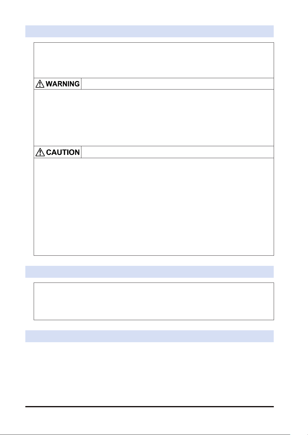
1.1.1 FP-XH Control Units
The following types are available depending on the number of points, power supply, and output
type.
Number of points 14 points / 30 points / 60 points
Power supply 100 to 240 V AC or 24 V DC
Output Relay or transistor (NPN output)
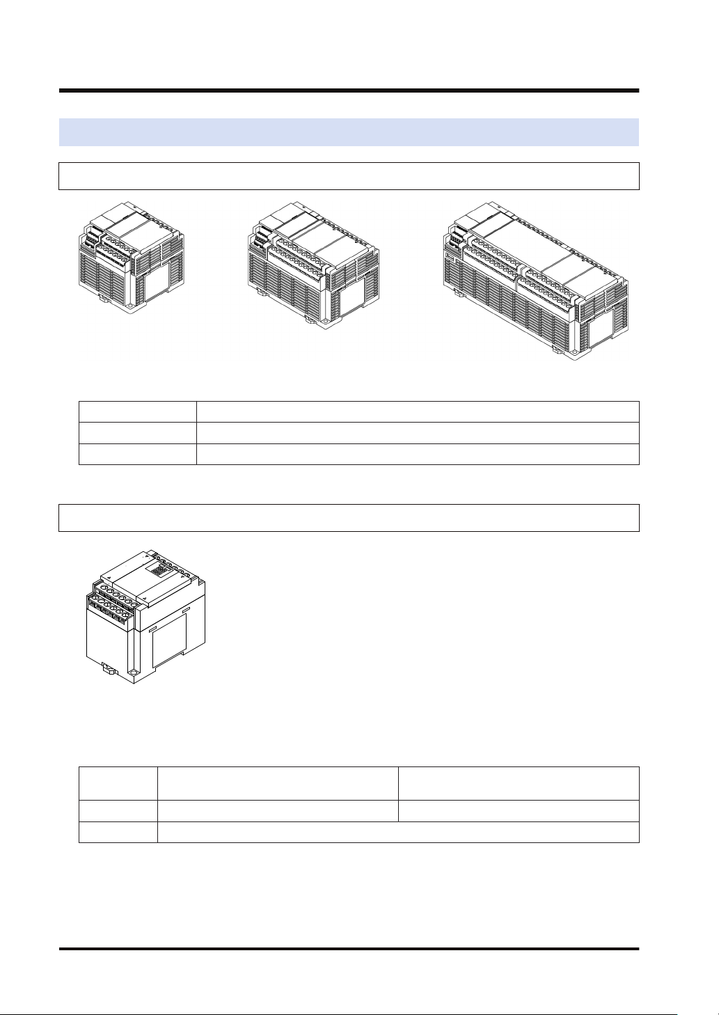
1.1.2 FP-X Expansion Units
The following types are available depending on the number of points, power supply, and output
type.
■
FP-X Expansion Units
Number of
points
Power supply No power supply 100 to 240 V AC or 24 V DC
Output Relay or transistor (NPN output or PNP output)
14 points (for output only) / 16 points (for input
only) / 16 (8/8) points
30 (16/14) points
1-2 WUME-FPXHBASG-01
Page 15
1.1 List of Units
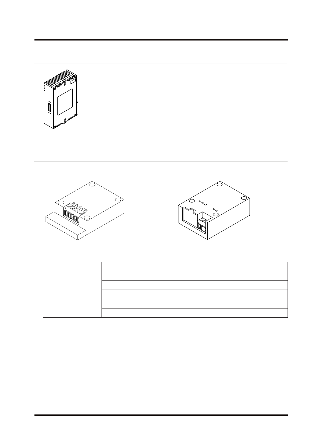
1.1.3 FP-X Expansion FP0 Adapter
The FP-X Expansion FP0 Adapter is an interface adapter that can be connected to the FP0
Series Expansion Unit / Intelligent Unit.
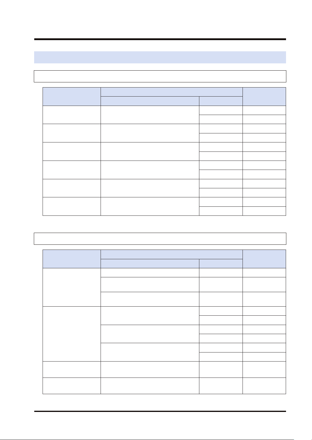
1.1.4 FP-X Extension Cassettes (Communication Cassettes)
The following types are available depending on the type of communication interface or the
number of channels.
RS-232C (5-wire type) x 1 channel
RS-232C (3-wire type) x 2 channels
Communication method
WUME-FPXHBASG-01 1-3
RS-485 / RS-422 x 1 channel
RS-485 x 1 channel + RS-232C (3-wire type) x 1 channel
RS-485 x 2 channels
Ethernet x 1 channel + RS-232C (3-wire type) x 1 channel
Page 16
1.1 List of Units
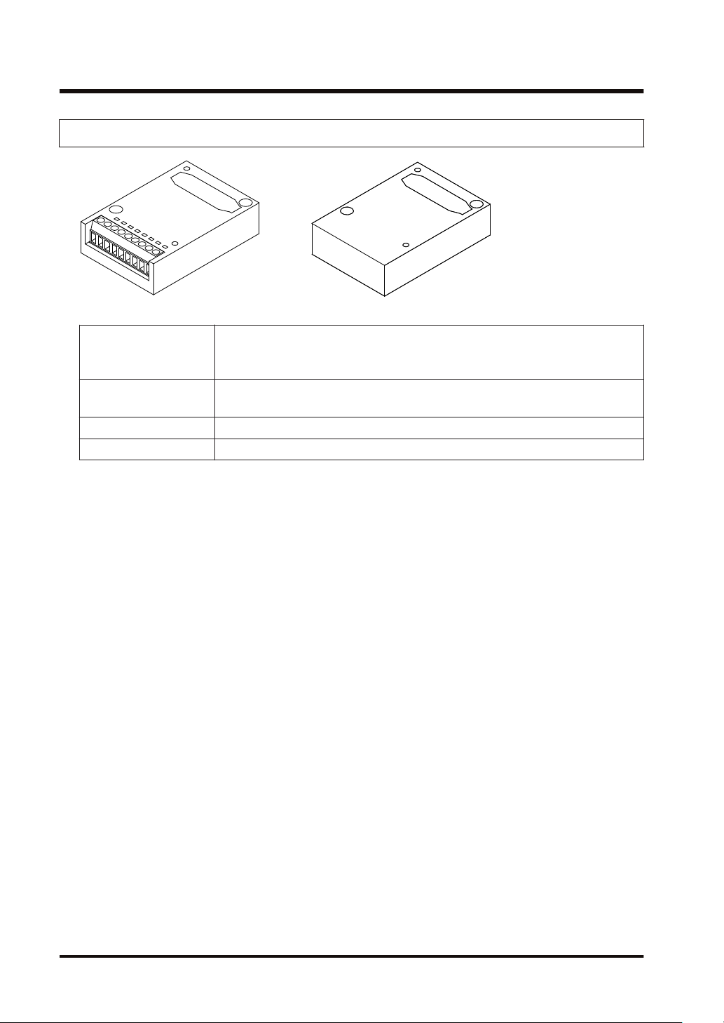
1.1.5 FP-X Extension Cassettes (Function Cassettes)
The following types are available depending on the output type and function.
Analog input x 2 channels
Analog I/O
Digital I/O
Pulse I/O High-speed counter × 2 channels + pulse output × 1 channel
Master memory Master memory + real-time clock
Analog output x 2 channels
Analog input x 2 channels + analog output x 1 channel
8-point input, 8-point transistor output
4-point input + 3-point transistor output
1-4 WUME-FPXHBASG-01
Page 17
1.2 List of Unit Model Numbers
1.2.1 FP-XH Control Units
1.2 List of Unit Model Numbers
Item name
FP-XH C14R
Control Unit
FP-XH C14T
Control Unit
FP-XH C30R
Control Unit
FP-XH C30T
Control Unit
FP-XH C60R
Control Unit
FP-XH C60T
Control Unit
Input and output specifications Power supply
8-point DC input, 6-point relay output
8-point DC input, 6-point transistor output
(NPN)
16-point DC input, 14-point relay output
16-point DC input, transistor output (NPN)
32-point DC input, 28-point relay output
32-point DC input, 28-point transistor output
(NPN)
Specifications
1.2.2 FP-X Expansion Units
Item name
Input and output specifications Power supply
8-point DC input, 8-point relay output - AFPX-E16R
FP-X E16
Expansion I/O Unit
8-point DC input, 8-point transistor output
(NPN)
8-point DC input, 8-point transistor output
(PNP)
16-point DC input, 14-point relay output
FP-X E30
Expansion I/O Unit
16-point DC input, 14-point transistor output
(NPN)
16-point DC input, 14-point transistor output
(PNP)
FP-X E16
Expansion Input Unit
FP-X E14R
Expansion Output Unit
(Note 1) An 8 cm expansion cable is provided with the Expansion Unit.
16-point DC input - AFPX-E16X
14-Point relay output - AFPX-E14YR
Specifications
Product no.
100 to 240 V AC AFPXHC14R
24 V DC AFPXHC14RD
100 to 240 V AC AFPXHC14T
24 V DC AFPXHC14TD
100 to 240 V AC AFPXHC30R
24 V DC AFPXHC30RD
100 to 240 V AC AFPXHC30T
24 V DC AFPXHC30TD
100 to 240 V AC AFPXHC60R
24 V DC AFPXHC60RD
100 to 240 V AC AFPXHC60T
24 V DC AFPXHC60TD
Product no.
- AFPX-E16T
- AFPX-E16P
100 to 240 V AC AFPX-E30R
24 V DC AFPX-E30RD
100 to 240 V AC AFPX-E30T
24 V DC AFPX-E30TD
100 to 240 V AC AFPX-E30P
24 V DC AFPX-E30PD
WUME-FPXHBASG-01 1-5
Page 18

1.2 List of Unit Model Numbers
1.2.3 FP-X Expansion FP0 Adapter
Name Specifications Product no.
FP-X Expansion FP0
Adapter
(Note 1) An 8 cm expansion cable is provided with the Expansion Unit.
1.2.4 FP-X Extension Cassettes (Communication Cassettes)
Name Specifications Product no.
FP-X Communication
Cassette
For connecting the FP0 Expansion Unit AFPX-EFP0
5-wire RS-232C x 1 channel AFPX-COM1
3-wire RS-232C x 2 channels AFPX-COM2
RS-485 / RS-422 (isolated) x 1 channel AFPX-COM3
RS-485 (isolated) x 1 channel + 3-wire RS-232C x 1 channel AFPX-COM4
RS-485 (isolated) x 2 channels (non-isolated between channels) AFPX-COM6
Ethernet port + 3-wire RS-232C x 1 channel AFPX-COM5
1.2.5 FP-X Extension Cassettes (Function Cassettes)
Name Specifications Product no.
FP-X Analog Input
Cassette
FP-X Analog Output
Cassette
Analog
FP-X Analog I/O Cassette
I/O
FP-X Thermocouple
Cassette
FP-X Resistance
Thermometer Cassette
FP-X Input Cassette 8-point DC input AFPX-IN8
Digital
I/O
FP-X Output Cassette 8-point transistor output (NPN) AFPX-TR8
FP-X Output Cassette 6-point transistor output (PNP) AFPX-TR6P
FP-X I/O Cassette
FP-X Pulse I/O Cassette
FP-X Master Memory Cassette Master memory + real-time clock AFPX-MRTC
Analog input (non-isolated) x 2 channels AFPX-AD2
Analog output (isolated) x 2 channels
(isolated between channels)
AFPX-DA2
Analog input (isolated) x 2 channels
(non-isolated between channels)
AFPX-A21
+ Analog output (isolated) x 1 channel
Thermocouple input (isolated) x 2 channels
(isolated between channels)
AFPX-TC2
Resistance thermometer input (isolated) x 2
channels
AFPX-RTD2
(isolated between channels)
4-point DC input + 3-point transistor output
(NPN)
High-speed counter × 2 channels + pulse
output × 1 channel
AFPX-IN4T3
AFPX-PLS
1-6 WUME-FPXHBASG-01
Page 19
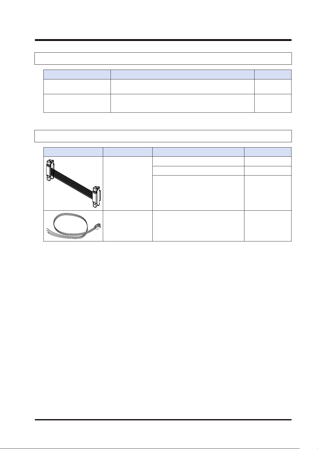
1.2.6 Options
Name Specifications Product no.
FP-XH Backup Battery
FP-X terminal block (C30/
C60)
1.2.7 Maintenance Parts
FP-X Expansion
Cable
1.2 List of Unit Model Numbers
Required when expanding the hold area of the operation
memory or when using the clock / calendar function.
For C30/C60 control unit for E30 expansion I/O unit with 21-pin
cover (no printing) 4 pcs/pack
Name Specifications Product no.
8 cm AFPX-EC08
30 cm AFPX-EC30
(Note 1)(Note 2)
80 cm AFPX-EC80
AFPABAT001
AFPX-TAN1
FP0
Power supply cable
(Note 1) An 8 cm expansion cable (AFPX-EC08) is provided with the FP-X Expansion Unit or with the FP-X
For the Expansion FP0 Adapter, length:
1 m
AFP0581
Expansion FP0 Adapter. The total length of the expansion cable should be within 160 cm.
(Note 2) If a longer expansion cable is used, an I/O check error may occur due to noise, etc. In such a case, it
is recommended that measures such as installing a ferrite core be taken.
WUME-FPXHBASG-01 1-7
Page 20
1.3 Restrictions on Combinations of Units
1.3 Restrictions on Combinations of Units
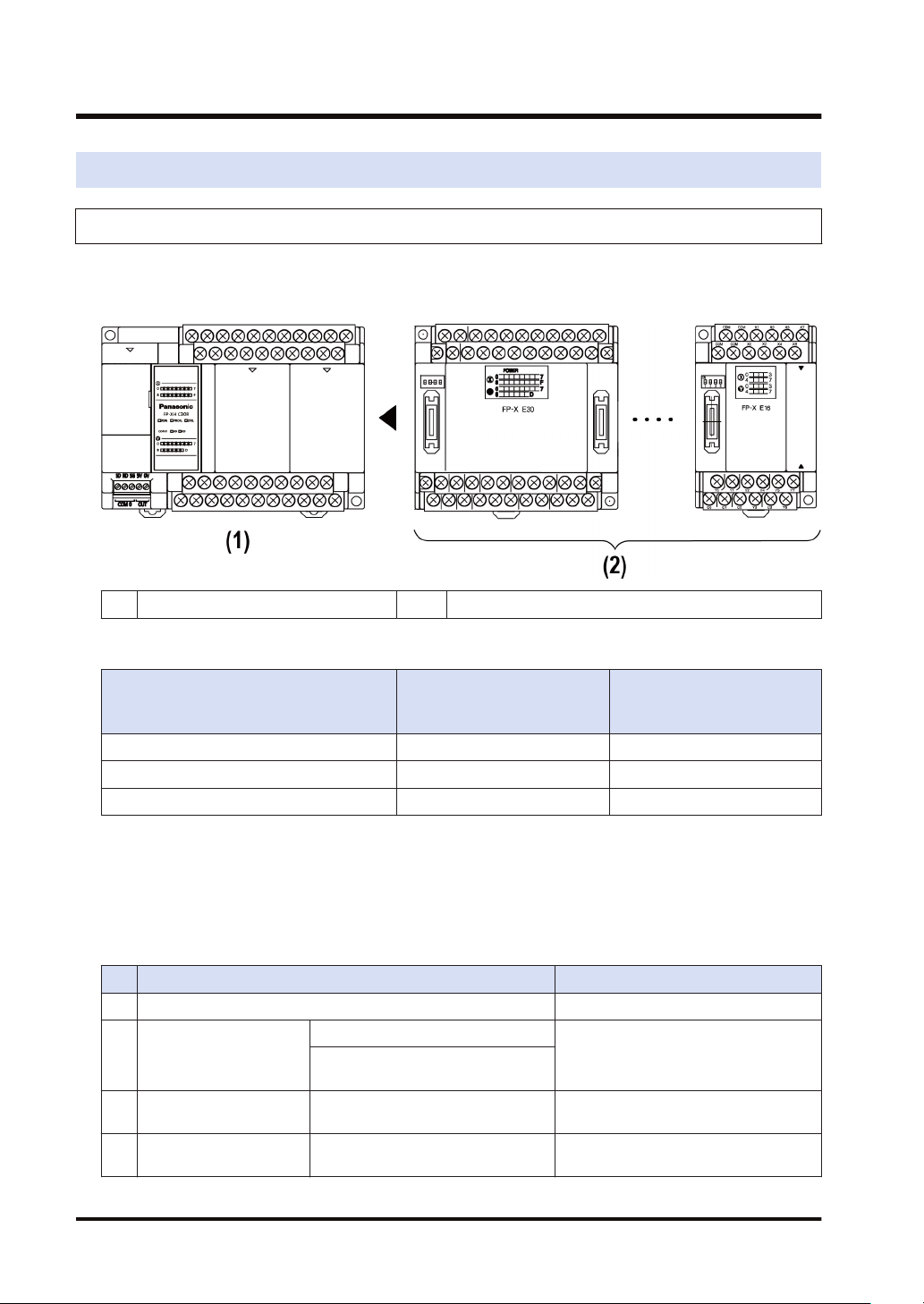
1.3.1 Restrictions on Using FP-X Expansion Units
■
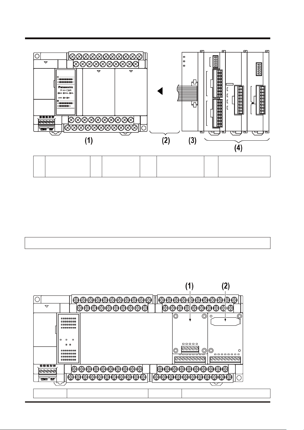
Restrictions on the number of Expansion Units and mounting order (1)
● Up to 8 Expansion Units can be connected.
(1) FP-XH Control Units (2) FP-X Expansion Units
■
Maximum number of control inputs / outputs
Control unit
Type of Control Unit
FP-XH C14 Control Unit 14 points Max. 254 points
FP-XH C30 Control Unit 30 points Max. 270 points
FP-XH C60 Control Unit 60 points Max. 300 points
■
Restrictions on combinations of Expansion Cables
No. of inputs / outputs of a
single control unit
FP-X-E30
No. of inputs / outputs when
using Expansion Units
● The total length of the expansion cables should be within 160 cm.
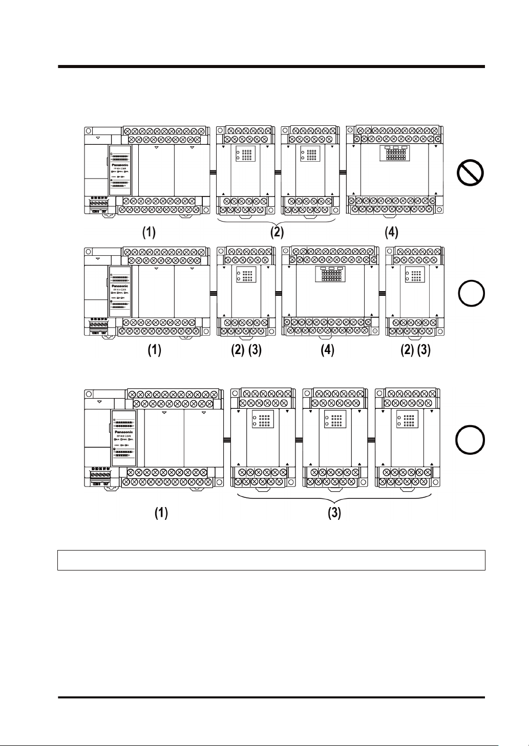
■
Restrictions on combinations of Expansion Units (2)
● The number of units which can be expanded depends on the Expansion Unit type.
Unit type Remarks
(1) FP-XH Control Unit
E14YR, E16R
(2) FP-X Expansion I/O Unit
(3) FP-X Expansion I/O Unit E16X, E16T, E16P (Ver. 3.0 or later)
(4) FP-X Expansion I/O Unit E30
E16X, E16T, E16P (earlier than Ver.
3.0)
Expansion I/O Unit that does not have a
built-in power supply
Expansion I/O Unit that does not have a
built-in power supply
Expansion I/O Unit that has a built-in
power supply
1-8 WUME-FPXHBASG-01
Page 21
1.3 Restrictions on Combinations of Units
● Among the FP-X Expansion I/O Units, those in the group (2) in the above table cannot be
connected next to each other. However, they can be connected to the right of the Expansion
I/O Unit that has a built-in power supply.
● Among the FP-X Expansion I/O Units that do not have a built-in power supply, those in the
group (3) in the above table can be connected together up to three units.
1.3.2 Restrictions on Using FP-X Expansion FP0 Adapter
■
FP-X Expansion FP0 Adapter installation position
● Up to three FP0 Expansion Units can be connected via the FP-X Expansion FP0 Adapter.
● Up to seven FP-X Expansion Units can be connected when using the FP-X Expansion FP0
Adapter.
● Only one FP-X Expansion FP0 Adapter can be connected at the last position of the FP-X
Expansion Bus. Install it on the right of the FP-X Expansion Unit / FP-X0 Expansion Unit.
WUME-FPXHBASG-01 1-9
Page 22
1.3 Restrictions on Combinations of Units
FP-XH
(1)
Control Unit
■
FP0 Expansion Unit / FP0 Intelligent Unit installation sequence
FP-X
(2)
Expansion Unit
FP-X
(3)
Expansion FP0
adapter
FP0 Expansion Unit
(4)
Intelligent Unit
● Install the FP0 Thermocouple Input Unit on the right side of all other FP0 Units. If it is
installed on the left side, the total precision will deteriorate.
● Install the FP0 CC-Link Unit on the right side of all other FP0 Units. There is no expansion
connector on the right side.
1.3.3 Restrictions on Combinations of Extension Cassettes
■
Extension Cassette mounting position (1)
● The FP-XH Control Unit is provided with two cassette mounting parts. In case of the C14
model, only the cassette mounting part 1 can be used.
(1) Cassette mounting part 1 (2) Cassette mounting part 2
1-10 WUME-FPXHBASG-01
Page 23
1.3 Restrictions on Combinations of Units
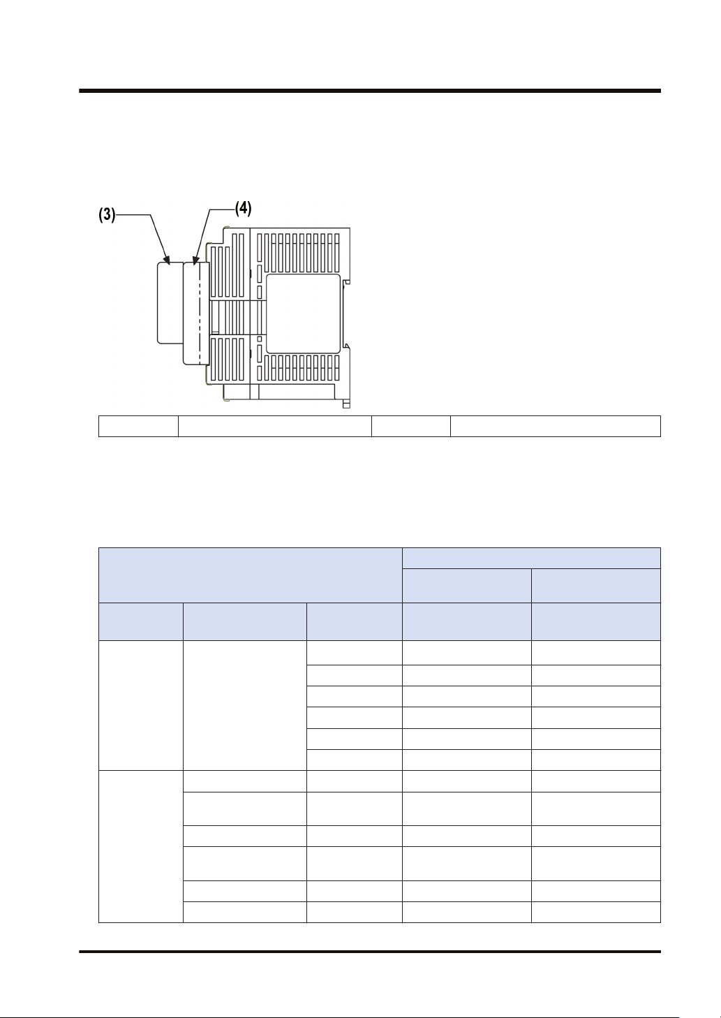
■
Extension Cassette mounting position (2)
● The Function Cassette can be put together with the Communication Cassette and mounted
on the same cassette mounting part. When doing so, be sure to put the Communication
Cassette on top of the Function Cassette.
(3) Communication Cassette (4) Function Cassette
■
Number of of Extension Cassettes to be mounted
● Up to two Function Cassettes and up to two Communication Cassettes can be mounted.
■
Types of Extension Cassettes and mounting position (●: Available, ○:
Conditionally available, Blank: Not available)
Mounting parts on the Control Unit
Cassette type
Type Item name Product number
AFPX-COM1
AFPX-COM2 ● ●
Communicatio
n Cassette
(Note 1)
Function
Cassette
(Note 3)
Communication
Cassette
Analog Input Cassette AFPX-AD2 ● ●
Analog Output
Cassette
Analog I/O Cassette AFPX-A21 ● ●
Thermocouple
Cassette
RTD Cassette AFPX-RTD2 ● ●
Input Cassette AFPX-IN8 ● ●
AFPX-COM3 ● ●
AFPX-COM4 ● ●
AFPX-COM5 ● ●
AFPX-COM6 ● ●
AFPX-DA2 ● ●
AFPX-TC2 ● ●
Cassette mounting
part 1
FP-XH Control
Unit
(Note 2)
●
Cassette mounting
part 2
FP-XH Control Unit
(excluding C14)
(Note 2)
●
WUME-FPXHBASG-01 1-11
Page 24

1.3 Restrictions on Combinations of Units
Mounting parts on the Control Unit
Cassette type
Type Item name Product number
Output Cassette AFPX-TR8 ● ●
Output Cassette AFPX-TR6P ● ●
I/O Cassette AFPX-IN4T3 ● ●
Pulse I/O Cassette AFPX-PLS
Master Memory
Cassette
(Note 1) When mounting it together with the Function Cassette, mount it on top of the Function Cassette.
AFPX-MRTC
(Note 2) With the AFPX-COM1, RS/CS control is possible.
(Note 3) When mounting the Function Cassette on C30, or C60 model, the Cassette can be mounted either on
the cassette mounting part 1 or cassette mounting part 2.
(Note 4) The Pulse I/O Cassette cannot be mounted on the Transistor Output Type Control Unit. If it is
mounted, the self-diagnostic error (27: Unit installed limit) will occur.
(Note 5) Only one FP-X Master Memory Cassette can be mounted. If two FP-X Master Memory Cassettes are
mounted, the self-diagnostic error (27: Unit installed limit) will occur.
Cassette mounting
part 1
FP-XH Control
Unit
(Note 4)
○
(Note 5)
○
Cassette mounting
part 2
FP-XH Control Unit
(excluding C14)
(Note 4)
○
(Note 5)
○
1.3.4 Restrictions on Communication Functions
● There are the following restrictions on functions to be used when using the communication
ports equipped with the Control Unit and Communication Cassettes.
● Allocated communication port numbers vary according to the mounting positions of
cassettes.
■
Types of communication ports / Communication Cassettes (●: Available, Blank:
Not available)
Allocated communication port no.
Product no.
Communication interface
Control
Unit
COM0 COM1 COM2 COM3 COM4
Control
Unit standard
equipment
AFPX-COM1
AFPX-COM2
RS-232C (3-wire type) x 1
channel
RS-232C (5-wire type) x 1
channel
RS-232C (3-wire type) x 2
channels
AFPX-COM3 RS-485 / RS-422 x 1 channel ● ●
RS-485 x 1 channel ● ●
AFPX-COM4
RS-232C (3-wire type) x 1
channel
Cassette mounting
●
part 1
part 2
● ●
● ● ● ●
● ●
Cassette mounting
1-12 WUME-FPXHBASG-01
Page 25

1.3 Restrictions on Combinations of Units
Allocated communication port no.
Product no. Communication interface
Control
Unit
COM0 COM1 COM2 COM3 COM4
Ethernet port x 1 channel ● ●
AFPX-COM5
RS-232C (3-wire type) x 1
channel
AFPX-COM6 RS-485 x 2 channels ● ● ● ●
(Note 1) The RS-232C port of the AFPX-COM1 is a 5-wire type, and the RS/CS control can be performed.
(Note 2) For the AFPX-COM1, select either RS-485 or RS-422. Use the switch on the Communication Cassette
to select the port.
(Note 3) For the AFPX-COM4, both 1-channel RS-485 and 1-channel RS-232C (3-wire type) can be used.
(Note 4) For the AFPX-COM5, both 1-channel Ethernet and 1-channel RS-232C (3-wire type) can be used.
■
Available functions for each communication port (●: Available, ○: Conditionally
available, Blank: Not available)
Communication functions to be used
PLC Link ○ ○
MEWTOCOL-COM
MODBUS-RTU
Master ● ● ● ● ●
Slave ● ● ● ● ●
Master ● ● ● ●
Slave ● ● ● ●
General-purpose communication ● ● ● ●
(Note 1) For the PLC link, either one of the standard COM0 port mounted in the Control Unit and the COM 1
port of a Cassette can be used.
(Note 2) The COM4 port only supports MEWTOCOL-COM communication. In addition, the communication
parameters (unit number, communication format, baud rate) when the power is ON are same as the
setting of the COM3 port. After RUN, you can also change the conditions by SYS1 instruction.
Control
Unit
COM0 COM1 COM2 COM3 COM4
Cassette mounting
part 1
Cassette mounting
part 2
● ●
Allocated communication port no.
Cassette mounting
part 1
Cassette mounting
part 2
1.3.5 Restrictions on Combined Use of Functions
● For the FP-XH series, communication with external devices can be performed via up to a
maximum of five communication interfaces in combination of the standard COM0 port
mounted in the Control Unit and the COM1 to COM4 ports of the Communication Cassette.
● When using all five ports (COM0 to COM4), the usable baud rate is up to 115.2 kbps and
usable pulse output function is up to 2 axes. When using four or less ports, the usable baud
rate is up to 230.4 kbps and usable pulse output function is up to 6 axes.
WUME-FPXHBASG-01 1-13
Page 26
1.4 Programming Tools
1.4 Programming Tools
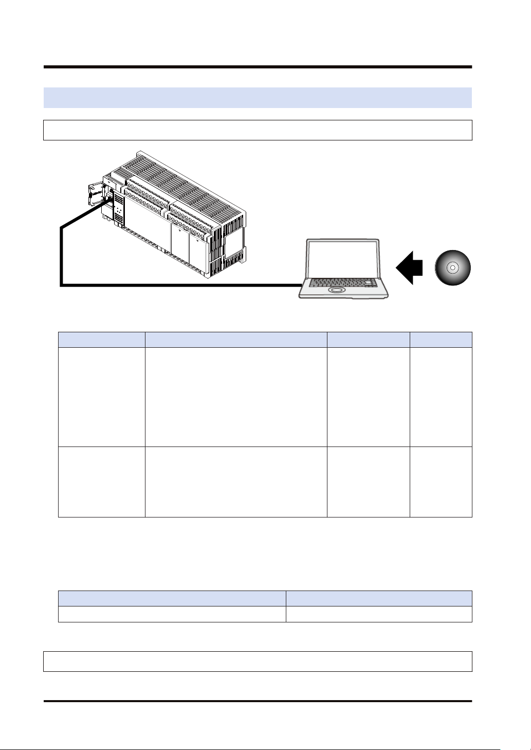
1.4.1 Software Usage Environment and Applicable Cables
■
Tool software
Software type Operating system Hard disk capacity Product no.
Windows
Windows
Windows
Control FPWIN GR7
Windows
bit version)
Windows
Windows
Windows
Windows
Control FPWIN Pro7
Windows
Windows
bit version)
(Note 1) The latest version is provided free of charge via our website (https://industrial.panasonic.com/ac/e/
dl_center/software/). Use the latest version.
(R)
10 (32-bit version / 64-bit version)
(R)
8.1 (32-bit version / 64-bit version)
(R)
8 (32-bit version / 64-bit version)
(R)
7 SP1 or later (32-bit version / 64-
(R)
Vista SP2
(R)
XP SP3
(R)
10 (32-bit version / 64-bit version)
(R)
8.1 (32-bit version / 64-bit version)
(R)
8 (32-bit version / 64-bit version)
(R)
7 SP1 or later (32-bit version / 64-
120 MB or more AFPSGR7EN
400 MB or more AFPSPR7A
■
PC connection cable
● Use a commercial USB cable.
Cable type Length
USB 2.0 cable (A:Mini B) Max. 5 m
1.4.2 Applicable software version
For using the FP-XH, the following software versions are required.
1-14 WUME-FPXHBASG-01
Page 27

Item Applicable version
Programming tool
software Control FPWIN
GR / GR7 / Pro7
Configurator PMX
C14/C30/C60
It is used for using the pulse output function in the table setting mode. It is
incorporated in the FPWIN GR / GR7 / Pro7 and can be started from the
option menu.
1.4 Programming Tools
FPWIN GR Ver. 2.93 or later
FPWIN GR7 Ver. 2.5 or later
FPWIN Pro7 Ver. 7.03 or later
WUME-FPXHBASG-01 1-15
Page 28

(MEMO)
1-16 WUME-FPXHBASG-01
Page 29

2 Control Unit Specifications
2.1 Names and Functions of Parts............................................................2-2
2.1.1 Names and Functions of Parts......................................................... 2-2
2.1.2 Specifications of Operation Indicator LEDs ..................................... 2-3
2.1.3 Specifications of COM0 Port............................................................ 2-4
2.2 Power Supply Specifications...............................................................2-5
2.2.1 AC Power Supply Type.................................................................... 2-5
2.2.2 AC Power Supply Type: Service Power Supply for Input Circuit ..... 2-5
2.2.3 DC Power Supply Type.................................................................... 2-6
2.3 Input and Output Specifications (Relay Output Type).........................2-7
2.3.1 Input Specifications.......................................................................... 2-7
2.3.2 Output Specifications ....................................................................... 2-8
2.4 Input and Output Specifications (Transistor Output Type) ..................2-9
2.4.1 Input Specifications.......................................................................... 2-9
2.4.2 Output Specifications ....................................................................... 2-10
2.5 Terminal Layout...................................................................................2-11
2.5.1 Relay Output (AC Power Supply Type)............................................ 2-11
2.5.2 Relay Output (DC Power Supply Type) ........................................... 2-12
2.5.3 Transistor Output (AC Power Supply Type) ..................................... 2-13
2.5.4 Transistor Output (DC Power Supply Type)..................................... 2-15
WUME-FPXHBASG-01
2-1
Page 30
2.1 Names and Functions of Parts
2.1 Names and Functions of Parts
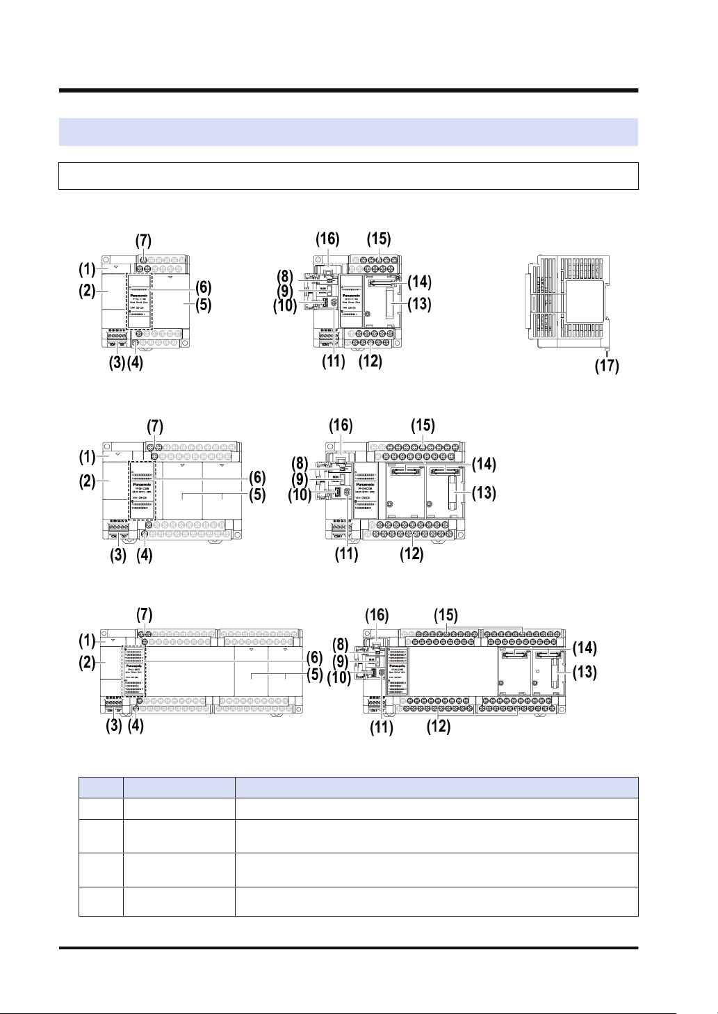
2.1.1 Names and Functions of Parts
■
FP-XH C14 Control Unit
■
FP-XH C30 Control Unit
■
FP-XH C60 Control Unit
■
Names and functions of parts
No. Name Function
(1) Battery cover This is a space for installing an optional backup battery.
(2) Operating unit cover
(3) COM0 port
Service power
(4)
supply
2-2 WUME-FPXHBASG-01
There are a built-in battery connector, RUN / PROG. mode selection switch,
USB port connector, and analog potentiometer.
Three-wire RS-232C port. A power supply terminal (5 V) is also provided for
connecting our Programmable Display GT Series.
It can be used as service power supply for the input circuit.
Page 31

2.1 Names and Functions of Parts
No. Name Function
terminal block for
input circuit
Cassette mounting
(5)
part cover
Operation monitor
LEDs /
(6)
Input and output
indicator LEDs
Power supply
(7)
terminal
(8) Battery connector This is used to insert the connector of a dedicated battery (AFPABAT001).
RUN / PROG. mode
(9)
selection switch
(10) USB port connector This is used to connect with a PC on which tool software is used.
Analog
(11)
potentiometer
(12) Output terminal This is used to connect an output device.
Expansion unit
(13)
connector
Extension cassette
(14)
connector
(15) Input terminal This is used to connect an input device.
(16) Battery holder
(17) DIN hook This is used to install the unit on a DIN rail.
(Note 1) Whether the switch is set to RUN or PROG., the mode can be switched through remote operation from
the tool software. When power is turned ON again, it operates in the mode set on the switch.
This is a space for installing an optional communication cassette and Function
Cassette.
Indicate the operation mode, error occurrence state, communication state of
COM0 port and input and output states.
This is used to connect the power supply to drive the Control Unit.
RUN (Up):
PROG.
(Down)
Sets to the RUN mode. The program is executed and operation
begins.
Sets to the PROG. mode.
Turning the potentiometer changes the values of special DT. It can be used for
the functions such as analog timer.
This is used to connect the expansion cable for mounting the Expansion Unit.
This is used to mount an optional Extension Cassette (Communication Cassette
or Function Cassette).
This is used to hold a dedicated battery for using the clock / calendar function
and extending the backup area of the operation memory. The dedicated battery
(AFPABAT001) is sold separately.
2.1.2 Specifications of Operation Indicator LEDs
WUME-FPXHBASG-01 2-3
Page 32

2.1 Names and Functions of Parts
No. LED name Color Data to display
(a) X
(b) Y
(c) RUN
(d) PROG.
(f)
COM0
(g) RD
(e) ERR. Red
SD
Gree
Indicates the input state.
n
Gree
Indicates the output state.
n
ON Turns ON when a program is being executed in RUN mode.
Gree
n
Flashes
ON Turns ON when the unit operation stops in PROG. mode.
Gree
n
Flashes
Gree
Flashes when data is sent via the COM0 port.
n
Gree
Flashes when data is received via the COM0 port.
n
Flashes Lit when an error is detected by self-diagnosis.
ON
RUN and PROG. LEDs flash alternately when the forced I/O
function is executed.
RUN and PROG. LEDs flash alternately when the forced I/O
function is executed.
This lights if a hardware error occurs, or operation slows
because of the program, and the watchdog timer is activated.
2.1.3 Specifications of COM0 Port
● This is a general-purpose three-wire RS-232C port.
● A 5 V power supply terminal is provided for connecting our Programmable Display GT02 /
GT02L Series.
■
Terminal layout
LED name Description
Send data (Unit to external
devices)
Receive data (External devices to
Unit)
5 V DC is output as the power supply for the Programmable Display GT Series.
This is a general-purpose three-wire RS-232C port.
COM 0
OUT
SD
RD
SG Signal grounding
5V
0V
2-4 WUME-FPXHBASG-01
Page 33

2.2 Power Supply Specifications
2.2.1 AC Power Supply Type
■
AC power supply type
2.2 Power Supply Specifications
Item
Rated voltage 100 to 240 V AC
Operating voltage range 85 to 264 V AC
Inrush current (240 V AC at ambient
temperature of 25℃)
Momentary power off time 10 ms (when using 200 V AC)
Frequency 50 / 60 Hz (47 to 63 Hz)
Leakage current 0.75 mA or less between input and protective earth terminals
Guaranteed life of internal power supply
part
Fuse Built-in (Cannot be replaced)
Isolation method Transformer insulation
Terminal screw M3
100 V AC
Consumption current
200 V AC
40 A or less 45 A or less
30,000 hours (at ambient temperature of 55℃)
C14R: 185 mA or less
C14T: 175 mA or less
C14R: 115 mA or less
C14T: 110 mA or less
C14 C30/C60
Specifications
C30R: 330 mA or less
C30T: 310 mA or less
C60R: 380 mA or less
C60T: 335 mA or less
C30R: 200 mA or less
C30T: 190 mA or less
C60R: 235 mA or less
C60T: 205 mA or less
2.2.2 AC Power Supply Type: Service Power Supply for Input Circuit
■
AC power supply type: Specifications of service power supply for input circuit
Item
Rated voltage 24 V DC
Operating voltage range 21.6 to 26.4 V DC
Rated output current 0.15 A 0.4 A
Overcurrent protection function Available
Terminal screw M3
WUME-FPXHBASG-01 2-5
C14 C30/C60
Specifications
Page 34

2.2 Power Supply Specifications
2.2.3 DC Power Supply Type
■
DC power supply type
Item
Rated voltage 24 V DC
Operating voltage range 21.6 to 26.4 V DC
Inrush current 12 A or less (240 V AC at ambient temperature of 25℃)
Momentary power off time 10 ms
Guaranteed life of internal power supply
part
Fuse Built-in (Cannot be replaced)
Isolation method Non-isolated
Terminal screw M3
Consumption current
30,000 hours (at ambient temperature of 55℃)
C14RD: 95 mA or less
C14TD: 90 mA or less
C30RD: 160 mA or less
C30TD: 115 mA or less
C60RD: 275 mA or less
C60TD: 170 mA or less
Specifications
C14/C30/C60
2-6 WUME-FPXHBASG-01
Page 35

2.3 Input and Output Specifications (Relay Output Type)
2.3 Input and Output Specifications (Relay Output Type)
2.3.1 Input Specifications
■
Specifications
Item
Isolation method Optical coupler
Rated input voltage 24 V DC
Operating voltage range 21.6 to 26.4 V DC
Rated input current Approx. 4.7 mA (X0 to X7) / Approx. 4.3 mA (X8 or later)
Input points per common
Min. ON voltage / Min. ON current 19.2 V DC/3 mA
Max. OFF voltage / Max. OFF current 2.4 V DC/1 mA
Input impedance 5.1 kΩ (X0 to X7) / 5.6 kΩ (X8 or later)
Response time
Operating mode indicator LED
EN61131-2 applicable type Type3 (However, the above specifications must be met.)
(Note 1) These specifications apply when the rating is 24 V DC and the ambient temperature is 25 °C.
(Note 1)
OFF→ON
ON→OFF Same as above.
C14R C30R C60R
8 points/common 16 points/common
(Either the positive or negative of input power supply can be
connected to common terminal.)
0.6 ms or less (For normal input)
X0 to X7
X8 or later 0.6 ms or less
50 μs or less (For high-speed counter, pulse catch
and interrupt input settings)
Specifications
16 points/common x
2
■
Internal circuit diagram
X0 to Xn
X0 to X7: R1 = 5.1 kΩ, R2 = 3 kΩ
X8 to Xn: R1 = 5.6 kΩ, R2 = 1 kΩ
WUME-FPXHBASG-01 2-7
Page 36

2.3 Input and Output Specifications (Relay Output Type)
2.3.2 Output Specifications
■
Specifications
Item
Isolation method Relay insulation
Output type 1a relay output
Rated control capacity
Per common 6A or less 8A or less
Input points per common
Response time
Life
Operating mode indicator LED
EN61131-2 Applicable type Type3 (However, the above specifications must be met.)
■
Internal circuit diagram
OFF→ON Approx. 10 ms
ON→OFF Approx. 8 ms
Mechanical
Electrical
C14R C30R C60R
2 A at 250 V AC, 2 A at 30 V DC (resistive load)
1-point common x 3
3-point common x 1
20 million times or more (Frequency of switching: 180 times/
min.)
100 thousand times or more (Frequency of switching at the
rated control capacity: 20 times/min.)
Specifications
1-point common x 2
4-point common x 3
1-point common x 6
2-point common x 1
4-point common x 5
2-8 WUME-FPXHBASG-01
Page 37

2.4 Input and Output Specifications (Transistor Output Type)
2.4 Input and Output Specifications (Transistor Output Type)
2.4.1 Input Specifications
■
Specifications
Item
Isolation method Optical coupler
Rated input voltage 24 V DC
Operating voltage range 21.6 to 26.4 V DC
Rated input current
Input points per common
Min. ON voltage / Min. ON current 19.2 V DC/3 mA
Max. OFF voltage / Max. OFF current 2.4 V DC/1 mA
Input impedance
Response
(Note 1)
time
Operating mode indicator LED
EN61131-2 applicable type Type3 (However, the above specifications must be met.)
(Note 1) These specifications apply when the rating is 24 V DC and the ambient temperature is 25 °C.
OFF→ON
ON→OFF Same as above.
Specifications
C14T C30T C60T
Approx. 12 mA (X0 to X3) / Approx. 4.7 mA (X4 to X7) / Approx. 4.3
mA (X8 or later)
8 points/common 16 points/common 16 points/common x 2
(Either the positive or negative of input power supply can be connected
to common terminal.)
Approx. 2 kΩ (X0 to X3) / Approx. 5.1 kΩ (X4 to X7) / Approx. 5.6 kΩ
(X8 or later)
135 μs or less (For normal input)
X0 to X3
X4 to X7
X8 or later 0.6 ms or less
5 μs or less (For high-speed counter, pulse catch and
interrupt input settings)
135 μs or less (For normal input)
50 μs or less (For high-speed counter, pulse catch and
interrupt input settings)
■
Internal circuit diagram
X0 to X3 X4 to Xn
R1 = 2 kΩ, R2 = 680 kΩ
X4 to X7: R1 = 5.1 kΩ, R2 = 3 kΩ
X8 to Xn: R1 = 5.6 kΩ, R2 = 1 kΩ
WUME-FPXHBASG-01 2-9
Page 38

2.4 Input and Output Specifications (Transistor Output Type)
2.4.2 Output Specifications
■
Specifications
Item
Isolation method Optical coupler
Output type NPN open collector
Rated load voltage 5 to 24 V DC
Allowable load voltage range 4.75 to 26.4 V DC
Rated load current 0.5 A
Max. inrush current 1.5 A
Off state leakage current 1 μA or less
ON-state max. voltage drop 0.3 V DC or less
Overcurrent protection
function
Input points per common 6-point common
Response
time
(Note 1)
Surge absorber Zener diode
Operating mode indicator LED
EN61131-2 applicable type Type3 (However, the above specifications must be met.)
(Note 1) These specifications apply when the ambient temperature is 25 °C.
OFF→ON
ON→OFF
None
1 ms or less (Y4 or later)
1 ms or less (Y4 or later)
C14T C30T C60T
2 μs or less (Y0 to Y3)
8 μs or less (Y0 to Y3)
Specifications
6-point common x 1
8-point common x 1
2 μs or less (Y0 to Y7)
1 ms or less (Y8 or later)
8 μs or less (Y0 to Y7)
1 ms or less (Y8 or later)
6-point common x 2
8-point common x 2
2 μs or less (Y0 to YB)
1 ms or less (YC or later)
8 μs or less (Y0 to YB)
1 ms or less (YC or later)
■
Internal circuit diagram
2-10 WUME-FPXHBASG-01
Page 39

2.5 Terminal Layout
2.5 Terminal Layout
2.5.1 Relay Output (AC Power Supply Type)
Input terminal
COM terminals in the same terminal block are connected within the unit. However, input
terminal 1 and input terminal 2 of the C60 are independent from other terminals. (These
terminals are not connected internally.)
Output terminal
Each COM terminal (C0, C1 …) is independent. Use them in the range surrounded by the bold
black lines.
■
AFPXHC14R
■
AFPXHC30R
WUME-FPXHBASG-01 2-11
Page 40

2.5 Terminal Layout
■
AFPX-C60R
2.5.2 Relay Output (DC Power Supply Type)
Input terminal
COM terminals in the same terminal block are connected within the unit. However, input
terminal 1 and input terminal 2 of the C60 are independent from other terminals. (These
terminals are not connected internally.)
Output terminal
Each COM terminal (C0, C1 …) is independent. Use them in the range surrounded by the bold
black lines.
■
AFPXHC14RD
2-12 WUME-FPXHBASG-01
Page 41

■
AFPXHC30RD
■
AFPX-C60RD
2.5 Terminal Layout
2.5.3 Transistor Output (AC Power Supply Type)
Input terminal
COM terminals in the same terminal block are connected within the unit. However, input
terminal 1 and input terminal 2 of the C60 are independent from other terminals. (These
terminals are not connected internally.)
Output terminal
The negative terminals are connected within the unit.
WUME-FPXHBASG-01 2-13
Page 42

2.5 Terminal Layout
■
AFPXHC14T
■
AFPXHC30T
■
AFPXHC60T
2-14 WUME-FPXHBASG-01
Page 43

2.5 Terminal Layout
2.5.4 Transistor Output (DC Power Supply Type)
Input terminal
COM terminals in the same terminal block are connected within the unit. However, input
terminal 1 and input terminal 2 of the C60 are independent from other terminals. (These
terminals are not connected internally.)
Output terminal
The negative terminals are connected within the unit.
■
AFPXHC14TD
■
AFPXHC30TD
WUME-FPXHBASG-01 2-15
Page 44

2.5 Terminal Layout
■
AFPXC60TD
2-16 WUME-FPXHBASG-01
Page 45

3 Allocation of I/O Numbers
3.1 Basics of I/O Allocation.......................................................................3-2
3.1.1 How to Count I/O Numbers.............................................................. 3-2
3.1.2 Concept of I/O Number Allocation ................................................... 3-2
3.2 List of I/O Numbers for Each Unit .......................................................3-4
3.2.1 FP-XH Control Units ........................................................................ 3-4
3.2.2 FP-X Expansion Units...................................................................... 3-4
3.2.3 FP-X Function Cassettes ................................................................. 3-4
3.3 Allocation of FP0 Expansion Units......................................................3-6
3.3.1 Concept of I/O Number Allocation ................................................... 3-6
3.3.2 Types and I/O Numbers of FP0R Expansion Units.......................... 3-7
3.3.3 Types and I/O Numbers of FP0 Expansion Units ............................ 3-8
WUME-FPXHBASG-01
3-1
Page 46

3.1 Basics of I/O Allocation
3.1 Basics of I/O Allocation
3.1.1 How to Count I/O Numbers
■
How to count and express I/O numbers
● Since I/O number are handled in units of 16 points, they are expressed as a combination of a
device type code and the lowest-digit of a decimal or hexadecimal number.
● In the case of external inputs, they are expressed as X0 to X9 and XA to XF. In the case of
external outputs, they are expressed as Y0 to Y9 and YA to YF.
3.1.2 Concept of I/O Number Allocation
■
I/O numbers of Control Unit
Fixed areas are allocated to I/O numbers.
■
I/O numbers of Expansion Unit
The starting number allocated to each Expansion Unit varies according to the installation
position.
■
I/O numbers allocated to Function Cassette
Fixed areas are allocated to I/O numbers according to the installation position.
■
List of I/O numbers
Unit type and installation position
(1) Control unit X0 to X9F WX0 to WX9 Y0 to Y9F WY0 to WY9
Input Output
I/O number I/O number
3-2 WUME-FPXHBASG-01
Page 47

3.1 Basics of I/O Allocation
Unit type and installation position
(2) Cassette mounting part 1
(Slot 0)
(3) Cassette mounting part 2
(Slot 1)
Input Output
I/O number I/O number
X100 to X19F WX10 to WX19 Y100 to Y19F WY10 to WY19
X200 to X29F WX20 to WX29 Y200 to Y29F WY20 to WY29
(4) 1st Expansion Unit X300 to X39F WX30 to WX39 Y300 to Y39F WY30 to WY39
(5) 2nd Expansion Unit X400 to X49F WX40 to WX49 Y400 to Y49F WY40 to WY49
(6) 3rd Expansion Unit X500 to X59F WX50 to WX59 Y500 to Y59F WY50 to WY59
(7) 4th Expansion Unit X600 to X69F WX60 to WX69 Y600 to Y69F WY60 to WY69
(8) 5th Expansion Unit X700 to X79F WX70 to WX79 Y700 to Y79F WY70 to WY79
(9) 6th Expansion Unit X800 to X89F WX80 to WX89 Y800 to Y89F WY80 to WY89
(10) 7th Expansion Unit X900 to X99F WX90 to WX99 Y900 to Y99F WY90 to WY99
(11)
8th Expansion Unit
(Note 1) The ranges of the I/O numbers which are actually used vary according to the types of cassettes and
Expansion Units.
X1000 to
X109F
WX100 to
WX109
Y1000 to
Y109F
WY100 to WY109
WUME-FPXHBASG-01 3-3
Page 48

3.2 List of I/O Numbers for Each Unit
3.2 List of I/O Numbers for Each Unit
3.2.1 FP-XH Control Units
■
List of I/O numbers
Input Output
Unit type
C14 8 points X0 to X7 6 points Y0 to Y5
C30 16 points X0 to X9, XA to XF 14 points Y0 to Y9, YA to YD
C60 32 points
No. of
input
points
I/O number
X0 to X9, XA to XF
X10 to X19, X1A to X1F
3.2.2 FP-X Expansion Units
■
List of I/O numbers
No. of
output
points
28 points
I/O number
Y0 to Y9, YA to YD
Y10 to Y19, Y1A to Y1D
Input Output
Unit type
E16 8 points X300 to X307 8 points Y300 to Y305
E30 16 points
E16X 16 points
E14YR - - 14 points
(Note 1) Each I/O number shown in the above table indicates the I/O number of the Expansion Unit connected
first. The I/O numbers vary according to the order of installation.
No. of
input
points
I/O number
X300 to X309, X30A to
X30F
X300 to X309, X30A to
X30F
No. of
output
points
14 points
- -
I/O number
Y300 to Y309, Y30A to
Y30D
Y300 to Y309, Y30A to
Y30D
3.2.3 FP-X Function Cassettes
■
List of I/O numbers (Analog I/O cassettes)
Installati
on
position
Cassette
mounting
part 1
Type
Analog Input Cassette: AD2 2ch WX10, WX11 - -
Analog Output Cassette: DA2 - - 2ch WY10, WY11
Input Output
No. of
input
points
I/O number
No. of
output
points
I/O number
3-4 WUME-FPXHBASG-01
Page 49

3.2 List of I/O Numbers for Each Unit
Installati
on
position
Cassette
mounting
part 2
■
Installati
on
position
Cassette
mounting
part 1
Cassette
mounting
part 2
Type
Analog I/O Cassette: A21 2ch WX10, WX11 1ch WY10
Thermocouple Input Cassette:
TC2
Resistance Thermometer Input
Cassette: RTD2
Analog Input Cassette: AD2 2ch WX20, WX21 - -
Analog Output Cassette: DA2 - - 2ch WY20, WY21
Analog I/O Cassette: A21 2ch WX20, WX21 1ch WY20
Thermocouple Input Cassette:
TC2
Resistance Thermometer Input
Cassette: RTD2
List of I/O numbers (Digital I/O cassettes)
Type
Input Cassette: IN8 8 points X100 to X107 - -
Output Cassette: TR8 - - 8 points Y100 to Y107
Output Cassette: TR6P - - 6 points Y100 to Y105
I/O Cassette: IN4T3 4 points X100 to X103 3 points Y100 to Y102
Input Cassette: IN8 8 points X200 to X207 - -
Output Cassette: TR8 - - 8 points Y200 to Y207
Output Cassette: TR6P - - 6 points Y200 to Y205
I/O Cassette: IN4T3 4 points X200 to X203 3 points Y200 to Y202
Input Output
No. of
input
points
2ch WX10, WX11 - -
2ch WX10, WX11 - -
2ch WX20, WX21 - -
2ch WX20, WX21 - -
Input Output
No. of
input
points
I/O number
I/O number
No. of
output
points
No. of
output
points
I/O number
I/O number
■
List of I/O numbers (Pulse I/O cassettes)
Installati
on
position
Cassette
mounting
part 1
Cassette
mounting
part 2
Type
High-speed Counter Cassette 3 points X100 to X102 - -
Pulse Output Cassette - - 3 points Y100 to Y102
High-speed Counter Input
Cassette
Pulse Output Cassette - - 3 points Y200 to Y202
Input Output
No. of
input
points
3 points X200 to X202 - -
I/O number
No. of
output
points
I/O number
WUME-FPXHBASG-01 3-5
Page 50

3.3 Allocation of FP0 Expansion Units
3.3 Allocation of FP0 Expansion Units
3.3.1 Concept of I/O Number Allocation
■
I/O numbers of FP0 Expansion Units and FP0 Intelligent Units
● The starting number allocated to each FP0 expansion block varies according to the
installation position of the FP-X Expansion FP0 Adapter.
● The starting number allocated to each unit varies according to the installation order of the
FP0 Expansion Units and FP0 Intelligent Units.
FP-X
(1)
Expansion FP0
Adapter
■
List of I/O numbers
FP-X
Expansion
FP0
Adapter
installation
position
1st Expansion
Unit
2nd
Expansion
Unit
3rd Expansion
Unit
4th Expansion
Unit
5th Expansion
Unit
6th Expansion
Unit
7th Expansion
Unit
X300 to X31F Y300 to Y31F X320 to X33F Y320 to Y33F X340 to X35F Y340 to Y35F
X400 to X41F Y400 to Y41F X420 to X43F Y420 to Y43F X440 to X45F Y440 to Y45F
X500 to X51F Y500 to Y51F X520 to X53F Y520 to Y53F X540 to X55F Y540 to Y55F
X600 to X61F Y600 to Y61F X620 to X63F Y620 to Y63F X640 to X65F Y640 to Y65F
X700 to X71F Y700 to Y71F X720 to X73F Y720 to Y73F X740 to X75F Y740 to Y75F
X800 to X81F Y800 to Y81F X820 to X83F Y820 to Y83F X840 to X85F Y840 to Y85F
X900 to X91F Y900 to Y91F X920 to X93F Y920 to Y93F X940 to X95F Y940 to Y95F
FP0
(2)
Expansion unit
1
FP0 Expansion Unit installation order
Expansion unit 1 Expansion unit 2 Expansion unit 3
Input Output Input Output Input Output
FP0
(3)
Expansion unit 2
FP0
(4)
Expansion unit 3
3-6 WUME-FPXHBASG-01
Page 51

3.3 Allocation of FP0 Expansion Units
FP-X
Expansion
FP0
Expansion unit 1 Expansion unit 2 Expansion unit 3
FP0 Expansion Unit installation order
Adapter
installation
Input Output Input Output Input Output
position
8th Expansion
Unit
(Note 1) The ranges of the I/O numbers which are actually used vary according to the types of cassettes and
X1000
to X101F
Expansion Units.
Y1000
to Y101F
X1020
to X103F
Y1020
to Y103F
X1040
to X105F
Y1040
to Y105F
3.3.2 Types and I/O Numbers of FP0R Expansion Units
The following table shows the I/O numbers when FP-X Expansion FP0 Adapter is connected to
the Control Unit as the first Expansion Unit.
■
List of I/O numbers (1st Expansion Unit)
FP0R
Expansion Unit
FP0R
Analog Input
Unit
Unit type Number of
allocation
AFP0RE8X Input (8 points) X300 to X307 X320 to X327 X340 to X347
Input (4 points) X300 to X303 X320 to X323 X340 to X343
AFP0RE8R
Output (4
points)
AFP0E8YT/P
AFP0RE8YR
Output (8
points)
AFP0RE16X Input (16 points) X300 to X30F X320 to X32F X340 to X34F
AFP0RE16R
AFP0RE16T/P
AFP0RE16YT/P
Input (8 points) X300 to X307 X320 to X327 X340 to X347
Output (8
points)
Output (16
points)
Input (16 points) X300 to X30F X320 to X32F X340 to X34F
AFP0RE32T/P
Output (16
points)
Input (16 points)
CH0, 2, 4, 6
Input (16 points)
CH1, 3, 5, 7
AFP0RAD4
1)
AFP0RAD8
(Note
Output (16
points)
Range setting
Output (16
points)
Averaging
setting
Expansion unit1Expansion unit2Expansion unit
3
Y300 to Y303 Y320 to Y323 Y340 to Y343
Y300 to Y307 Y320 to Y327 Y340 to Y347
Y300 to Y307 Y320 to Y327 Y340 to Y347
Y300 to Y30F Y320 to Y32F Y340 to Y34F
Y300 to Y30F Y320 to Y32F Y340 to Y34F
WX30
(X300 to X30F)
WX31
(X310 to X31F)
WY30
(Y300 to Y30F)
WY31
(Y310 to Y31F)
WX32
(X320 to X32F)
WX33
(X330 to X33F)
WY32
(Y320 to Y32F)
WY33
(Y330 to Y33F)
WX34
(X340 to X34F)
WX35
(X350 to X35F)
WY34
(Y340 to Y34F)
WY35
(Y350 to Y35F)
WUME-FPXHBASG-01 3-7
Page 52

3.3 Allocation of FP0 Expansion Units
FP0R
Analog Output
Unit
Unit type Number of
allocation
Input (32 points)
Status
Output (16
AFP0RDA4
points)
CH0, 2
(Note 2)
Expansion unit1Expansion unit2Expansion unit
3
WX30
(X300 to X30F)
WX31
(X310 to X31F)
WY30
(Y300 to Y30F)
WX32
(X320 to X32F)
WX33
(X330 to X33F)
WY32
(Y320 to Y32F)
WX34
(X340 to X34F)
WX35
(X350 to X35F)
WY34
(Y340 to Y34F)
Output (16
FP0R
Analog I/O Unit
AFP0RA21
3)
AFP0RA42
(Note
points)
CH1, 3
(Note 2)
Input (16 points)
CH0, 2
Input (16 points)
CH1, 3
Output (16
points)
CH0
(Note 4)
WY31
(Y310 to Y31F)
WX30
(X300 to X30F)
WX31
(X310 to X31F)
WY30
(Y300 to Y30F)
WY33
(Y330 to Y33F)
WX32
(X320 to X32F)
WX33
(X330 to X33F)
WY32
(Y320 to Y32F)
WY35
(Y350 to Y35F)
WX34
(X340 to X34F)
WX35
(X350 to X35F)
WY34
(Y340 to Y34F)
Output (16
points)
CH1
(Note 4)
(Note 1) For AFP0RAD4, data of CH0 to CH3 is handled.
WY31
(Y310 to Y31F)
WY33
(Y330 to Y33F)
WY35
(Y350 to Y35F)
(Note 2) In the 14-bit mode, it can be used for switching the output range.
(Note 3) For AFP0RA21, data of input CH0 / CH1 and output CH0 is handled.
(Note 4) In the 14-bit mode, it can be used for switching the input and output ranges, and setting the averaging
for input.
3.3.3 Types and I/O Numbers of FP0 Expansion Units
The following table shows the I/O numbers when FP-X Expansion FP0 Adapter is connected to
the Control Unit as the first Expansion Unit.
■
List of I/O numbers (1st Expansion Unit)
Unit type Number of
allocation
FP0-E8X Input (8 points) X300 to X307 X320 to X327 X340 to X347
FP0
Expansion Unit
FP0-E8R
Input (4 points) X300 to X303 X320 to X323 X340 to X343
Output (4
points)
3-8 WUME-FPXHBASG-01
Expansion unit1Expansion unit2Expansion unit
3
Y300 to Y303 Y320 to Y323 Y340 to Y343
Page 53

3.3 Allocation of FP0 Expansion Units
Unit type Number of
allocation
FP0-E8YT/P
FP0-E8YR
Output (8
points)
Expansion unit1Expansion unit2Expansion unit
3
Y300 to Y307 Y320 to Y327 Y340 to Y347
FP0-E16X Input (16 points) X300 to X30F X320 to X32F X340 to X34F
FP0-E16R
FP0-E16T/P
FP0-E16YT/P
Input (8 points) X300 to X307 X320 to X327 X340 to X347
Output (8
points)
Output (16
points)
Y300 to Y307 Y320 to Y327 Y340 to Y347
Y300 to Y30F Y320 to Y32F Y340 to Y34F
Input (16 points) X300 to X30F X320 to X32F X340 to X34F
FP0
Analog
I/O Unit
FP0
A/D Conversion
Unit
FP0
Thermocouple
FP0-E32T/P
FP0-A21
FP0-A80
FP0-TC4
FP0-TC8
Output (16
points)
Input (16 points)
CH0
Input (16 points)
CH1
Output (16
points)
Input (16 points)
CH0, 2, 4, 6
Input (16 points)
CH1, 3, 5, 7
Y300 to Y30F Y320 to Y32F Y340 to Y34F
WX30
(X300 to X30F)
WX31
(X310 to X31F)
WY30
(Y300 to Y30F)
WX30
(X300 to X30F)
WX31
(X310 to X31F)
WX32
(X320 to X32F)
WX33
(X330 to X33F)
WY32
(Y320 to Y32F)
WX32
(X320 to X32F)
WX33
(X330 to X33F)
WX34
(X340 to X34F)
WX35
(X350 to X35F)
WY34
(Y340 to Y34F)
WX34
(X340 to X34F)
WX35
(X350 to X35F)
Unit
Input (16 points)
FP0
D/A Conversion
Unit
FP0-A04V
FP0-A04I
Output (16
points)
CH0, 2
Output (16
points)
CH1, 3
FP0
I/O Link
FP0-IOL
Unit
(Note 1) The data for each channel of the FP0 A/D Conversion Unit (FP0-A80), FP0 Thermocouple Unit (FP0-
Input (32 points) X300 to X31F X320 to X33F X340 to X35F
Output (32
points)
WX30
(X300 to X30F)
WY30
(Y300 to Y30F)
WY31
(Y310 to Y31F)
Y300 to Y31F Y320 to Y33F Y340 to Y35F
WX32
(X320 to X32F)
WY32
(Y320 to Y32F)
WY33
(Y330 to Y33F)
WX34
(X340 to X34F)
WY34
(Y340 to Y34F)
WY35
(Y350 to Y35F)
TC4 / FP0-TC8) and FP0 D/A Conversion Unit (FP0-A04V / FP0-A04I) is converted and read or
written by a user program including a conversion data switching flag.
(Note 2) Regarding the FP0 CC-Link Slave Unit, please refer to the exclusive manual. (The starting address
should be replaced.)
WUME-FPXHBASG-01 3-9
Page 54

(MEMO)
3-10 WUME-FPXHBASG-01
Page 55

4 Installation and Wiring
4.1 Installation...........................................................................................4-3
4.1.1 Installation Environment and Space ................................................ 4-3
4.2 Installation of Backup Battery .............................................................4-5
4.2.1 Installation of Backup Battery .......................................................... 4-5
4.3 Installation of Extension Cassette.......................................................4-6
4.3.1 Precautions When Installing the Extension Cassette ...................... 4-6
4.3.2 Installing the Communication Cassette............................................ 4-6
4.3.3 Installing the Function Cassette....................................................... 4-7
4.4 Connection of FP-X Expansion Unit ...................................................4-8
4.4.1 Setting of the Terminator Setting Switch .......................................... 4-8
4.4.2 Checking FP-X Expansion Cable..................................................... 4-8
4.4.3 Connection of FP-X Expansion Unit ................................................ 4-8
4.5 Connection of FP0 Expansion Unit.....................................................4-10
4.5.1 Connection of FP0 Expansion Unit .................................................. 4-10
4.5.2 Connection of FP-X Expansion FP0 Adapter................................... 4-10
4.6 Installation...........................................................................................4-12
4.6.1 Attachment to DIN Rail and Removal from DIN Rail........................ 4-12
4.6.2 Installation with screws .................................................................... 4-13
4.7 Wiring the Power Supply.....................................................................4-14
4.7.1 Common Precautions ...................................................................... 4-14
4.7.2 Grounding ........................................................................................ 4-14
4.7.3 Power Supply of Control Unit / Expansion Unit................................ 4-15
4.7.4 Power Supply of FP-X Expansion FP0 Adapter / FP0 Expansion
Unit.................................................................................................... 4-17
4.8 Wiring of Input and Output..................................................................4-19
4.8.1 Precautions on Wirings of Input and Output .................................... 4-19
4.8.2 Service Power Supply for Input and Output (Control Unit and
Expansion Unit: E30) ........................................................................ 4-19
4.8.3 Input Wiring...................................................................................... 4-19
4.8.4 Output Wiring ................................................................................... 4-21
4.9 Wiring the Terminal Block ...................................................................4-22
4.9.1 Suitable wires................................................................................... 4-22
4.9.2 Terminal block covers ...................................................................... 4-22
4.9.3 Installing / Removing the Terminal Block (C30 / C60)...................... 4-23
4.10 Safety Measures...............................................................................4-25
4.10.1 Safety Measures ............................................................................ 4-25
4.10.2 Instantaneous Power Failure ......................................................... 4-25
WUME-FPXHBASG-01
4-1
Page 56

4 Installation and Wiring
4.10.3 Watchdog Timer ............................................................................. 4-26
4-2 WUME-FPXHBASG-01
Page 57

4.1 Installation
4.1 Installation
4.1.1 Installation Environment and Space
■
Installation environment
Operating environment (Use the unit within the range of the general specifications when
installing)
● Surrounding air temperature: 0 to +55 °C
● Surrounding air humidity: 10 to 95% RH (at 25 °C and non-condensing)
● Pollution degree: 2
● Altitude: 2000 m above sea level or lower
● Device class: Class 1
● Overvoltage category: II or lower
● Installation location: In a control panel
The unit is intended for use within the above environment.
Do not use it in the following environments.
● Direct sunlight
● Sudden temperature changes causing condensation.
● Inflammable or corrosive gas.
● Excessive airborne dust, metal particles or saline matter.
● Benzine, paint thinner, alcohol or other organic solvents or strong alkaline solutions such as
ammonia or caustic soda.
● Direct vibration, shock or direct drop of water.
● Influence from power transmission lines, high voltage equipment, power cables, power
equipment, radio transmitters, or any other equipment that would generate high switching
surges. (100 mm or more)
■
Static electricity
● Before touching the unit, always touch a grounded piece of metal in order to discharge static
electricity.
● Do not touch connector pins directly.
■
Measures regarding heat discharge
● Always install the unit with the LED display section facing upward on the left side in order to
discharge heat.
WUME-FPXHBASG-01 4-3
Page 58

4.1 Installation
● Do not install the unit stacked up, horizontally or upside down. Doing so will prevent proper
cooling of the unit and cause overheating inside.
● Do not install the unit above devices which generate heat such as heaters, transformers or
large scale resistors.
■
Installation space
● Leave at least 50 mm of space between the top surface or the bottom surface of the unit and
the wiring duct or other device to secure sufficient ventilation space around the unit.
● In order to eliminate any effects from noise emission, power wires and electromagnetic
devices should be kept at least 100 mm away from the surfaces of the unit. When installing
the unit behind the doors of the control board, be especially careful to secure clearances as
above.
● Secure a space for connecting a cable for a programming tool.
4-4 WUME-FPXHBASG-01
Page 59

4.2 Installation of Backup Battery
4.2 Installation of Backup Battery
4.2.1 Installation of Backup Battery
● The procedure for installing the backup battery is as follows.
1. Open the operating unit cover and the battery cover.
2. Insert the backup battery in the battery holder.
3. Connect the battery connector.
4. Close the operating unit cover and the battery cover.
● Open the lever part for removing the backup battery.
● The backup battery is used for using the clock / calendar function and extending the backup
area of the operation memory.
● For details on the function and lifetime of backup battery and on hold area setting, refer to
"6.1 Memory Backup".
WUME-FPXHBASG-01 4-5
Page 60

4.3 Installation of Extension Cassette
4.3 Installation of Extension Cassette
4.3.1 Precautions When Installing the Extension Cassette
● Fix the Extension Cassette using the screws provided with the Control Unit.
● The screw tightening torque should be 0.3 to 0.5 N∙m. Securely tighten them.
■
Recommended screws
Type Input Quantity
Material: SW pan head (+) P-tight, 2.6 x
Tapping screw
● The installation must be carried out when the power supply is OFF. If the power supply is
ON, it may cause faults.
● Do not touch the back side and the connector of the Extension Cassette. The parts such
as IC may be damaged by static electricity.
16
Galvanized, trivalent chromate (black)
2 pcs./1 cassette
4.3.2 Installing the Communication Cassette
The communication cassette can be installed on the Control Unit or on the Function Cassette.
■
Installation on the Control Unit
● Connect the connector on the back of the communication cassette with the connector of the
cassette mounting part of the Control Unit, and secure the two positions, bottom left and top
right of the communication cassette, with the screws.
● It is no problem if the ribs remain. The AFPX-COM5 has no rib.
4-6 WUME-FPXHBASG-01
Page 61

4.3 Installation of Extension Cassette
■
Installation on the Function Cassette
● Connect the connector on the back of the Function Cassette with the connector of the
cassette mounting part of the Control Unit, and secure the two positions, bottom left and top
right of the Function Cassette, with the screws.
4.3.3 Installing the Function Cassette
The function cassette can be installed only on the Control Unit.
■
Installation on the Control Unit
● Connect the connector on the back of the Function Cassette with the connector of the
cassette mounting part of the Control Unit, and secure the two positions, bottom left and top
right of the Function Cassette, with the screws.
WUME-FPXHBASG-01 4-7
Page 62

ON
1 2 3 4
Terminator
setting DIP
switch of FP-X
Expansion Unit
4.4 Connection of FP-X Expansion Unit
4.4 Connection of FP-X Expansion Unit
4.4.1 Setting of the Terminator Setting Switch
● The terminator setting DIP switch on the Expansion Unit installed at the last position turn ON
all switches.
4.4.2 Checking FP-X Expansion Cable
4.4.3 Connection of FP-X Expansion Unit
● Connect the FP-X Expansion Unit and the FP-X Expansion FP0 Adapter to the Control Unit
using the exclusive expansion cable.
● An 8 cm expansion cable (AFPX-EC08) is provided with the FP-X Expansion Unit or with the
FP-X Expansion FP0 Adapter.
● If longer expansion cables are required for installing units on top of one another, separately
order 30 cm cable (AFPX-EC30) or 80 cm cable (AFPX-EC80).
● The total length of the expansion cables should be within 160 cm.
● Install the expansion cables (AFPX-EC30 or EC80) away from the devices and wirings
generating noises as much as possible.
Connect the FP-X Expansion Unit according to the following procedure.
1. Remove the expansion cover from the Control Unit and from the Expansion Unit.
2. Attach the expansion connector cable to the expansion connector part of the Control Unit
and to the expansion connector part (left side) of the expansion I/O unit.
4-8 WUME-FPXHBASG-01
Page 63

4.4 Connection of FP-X Expansion Unit
3. Put the units close together so that the expansion cable is housed between the units.
4. Install the expansion cover.
WUME-FPXHBASG-01 4-9
Page 64

4.5 Connection of FP0 Expansion Unit
4.5 Connection of FP0 Expansion Unit
4.5.1 Connection of FP0 Expansion Unit
● The FP0 Expansion Unit (Expansion Unit or Intelligent Unit) are connected to the right side of
the FP-X Expansion FP0 Adapter.
● To expand the unit, use the right-side connector and expansion hooks available for FP0
expansion on the side of the unit.
1. Lift the expansion hooks on the top and bottom sides of the unit with a screwdriver.
2. Align the pins at the four corners of the Expansion Unit.
Firmly match the connectors so that there is no gap between the units.
3. Press down the expansion hooks lifted in step 1 to secure the units.
4.5.2 Connection of FP-X Expansion FP0 Adapter
Connect the FP-X Expansion Unit according to the following procedure.
1. Remove the expansion cover from the Control Unit and from the Expansion Unit.
4-10 WUME-FPXHBASG-01
Page 65

4.5 Connection of FP0 Expansion Unit
2. Attach the expansion connector cable to the expansion connector part of the Control Unit
and to the expansion connector part (left side) of the FP-X Expansion FP0 Adapter.
3. Put the units close together so that the expansion cable is housed between the units.
4. Install the expansion cover.
● Although there is no terminator setting switch on the Expansion FP0 Adapter, the
terminator setting has been done within the Expansion FP0 Adapter. Turn off the
terminator setting switches of the other Expansion Units.
WUME-FPXHBASG-01 4-11
Page 66

4.6 Installation
4.6 Installation
4.6.1 Attachment to DIN Rail and Removal from DIN Rail
Attachment procedure
1. Fully pull down the DIN rail attachment lever on the back of the unit.
2. Fit the top of the unit attachment part into the DIN rail.
3. While pressing down the unit attachment part onto the DIN rail, fit the bottom of the unit
attachment part into the DIN rail.
4. Push up the DIN rail attachment lever on the back of the unit until it clicks to lock.
Removal procedure
1. Fully pull down the DIN rail attachment lever on the back of the unit.
2. Pull the bottom of the unit toward you.
3. While lifting the unit, remove it from the DIN rail.
4-12 WUME-FPXHBASG-01
Page 67

4.6.2 Installation with screws
Use M4 size screws for the installation.
4.6 Installation
● For details on installation dimensions, refer to "11.8.2 Mounting Dimensions".
WUME-FPXHBASG-01 4-13
Page 68

Circuit breaker
Mechanical
power
apparatus
Input/Output
devices
Insulated transformer
Insulated DC power supply
PLC
4.7 Wiring the Power Supply
4.7 Wiring the Power Supply
4.7.1 Common Precautions
■
Selection of power supply
● Use a low noise power supply.
● The inherent noise resistance is sufficient for the noise superimposed on the power wires,
however, the noise can be attenuated further by using the insulation transformer or insulated
power supply.
■
Isolation of power supply systems
Isolate the wiring systems to the units, input/output devices, and mechanical power apparatus.
4.7.2 Grounding
4-14 WUME-FPXHBASG-01
■
Power supply sequence
● The power supply sequence should be set up so that the power supply of the PLC turns off
before the power supplies for input and output.
● If the power supplies for input and output turns off before the power to the PLC, the control
unit will detect the input fluctuations and may begin an unscheduled operation.
● Ground the unit to obtain sufficient noise suppression.
● The point of grounding should be as close to the PLC unit as possible. The ground wire
should be as short as possible.
● Sharing the ground with another device may have an adverse effect. Therefore, be sure that
grounding is dedicated.
● The grounding terminal of the AC power supply unit should have a resistance of 100 Ω or
less.
Page 69

C30/C60
C14
Power supply terminal
(supply of 100 to 240 V AC)
Use twisted cables that are
thicker than 2 mm
2
( AWG14).
Form a circuit separate
from circuits for power
devices and I/O devices.
Breaker
Use an insulated transformer if
the influence of noise is large.
Grounding
terminal
Grounding connection
with a resistance of
100 Ω or less.
C30/C60
C14
Power supply terminal (supply of 24 V DC)
Use twisted cables that are
thicker than 2 mm2( AWG14).
Form a circuit separate from circuits
for power devices and I/O devices.
Breaker
Grounding
terminal
Grounding to
100 Ω or less
Insulated DC
power supply
4.7 Wiring the Power Supply
4.7.3 Power Supply of Control Unit / Expansion Unit
■
Power supply wiring (FP-XH Control Unit / FP-X Expansion Unit)
Unit Wiring diagram
AC power
supply
Type
DC power
supply
Type
■
Power supply voltage
Confirm that the voltage of the connected power supply is within the allowable range.
Model Rated input voltage Allowable voltage
range
AC power supply
type
DC power supply
type
100 to 240 V AC 85 to 264 V AC 50 / 60 Hz 47 to 63 Hz
24 V DC 20.4 to 28.8 V DC - -
WUME-FPXHBASG-01 4-15
Rated frequency Allowable
frequency range
Page 70

4.7 Wiring the Power Supply
● Power supply terminal locations are different among the units (C14, C30 and C60).
■
Power supply cable
● Use power supply cables that are thicker than 2 mm2 (AWG14) to minimize the voltage drop.
● Also, twist the power supply cables to minimize adverse effects from noise.
■
Suitable wires
Suitable wires Tightening torque
AWG22 to 14 (0.3 mm2 to 2.0 mm2)
■
Suitable crimp terminals
M3 terminal screws are used for the terminal. Use the following crimp terminals for wiring to the
terminals.
0.5 to 0.6 N∙m
Fork type terminal
■
Suitable crimp terminals
(Note 1)
Shape Part No. Suitable wires
Round type 2-MS3
Fork type 2-N3A
(Note 1)
Use wires that are thicker than 2 mm2.
1.04 to 2.63 mm
Round type terminal
2
● Using the power supply with voltage and frequency that are beyond the allowable ranges,
or using inappropriate wires may cause the fault of the power supply of the PLC.
4-16 WUME-FPXHBASG-01
Page 71

Power supply
cable
Green:
Function earth
Blue: 0 V
Brown:
24 V DC
Power supply cable
4.7 Wiring the Power Supply
4.7.4 Power Supply of FP-X Expansion FP0 Adapter / FP0 Expansion Unit
■
Wiring the power supply (FP-X Expansion FP0 Adapter / FP0 Expansion Unit)
Unit Wiring diagram
FP-X
FP0 Expansion
Adapter
FP0 Expansion Unit
FP0 Intelligent Unit
■
Selection of power supply
● To protect the system against erroneous voltage from the power supply line, use an insulated
power supply with an internal protective circuit (cable with reinforced insulation or double
insulation).
● The regulator on the unit is a non-Isolated type.
● To turn the power supplies ON simultaneously, supply the power for the Expansion FP0
Adapter from the service power supply for the input circuit of the FP-XH Control Unit.
■
Power supply voltage
● Confirm that the voltage of the connected power supply is within the allowable range.
Rated input voltage Allowable voltage range
24 V DC 20.4 to 28.8 V DC
■
Power supply cable
● Use the power supply cable (Part no.:AFP0581) that comes with the unit to connect the
power supply.
Brown: 24 V DC, Blue: 0 V, Green: Function earth
● Also, twist the power supply cables to minimize adverse effects from noise.
■
Power supply sequence
● To ensure and ease the power supply sequence of the Expansion FP0 Adapter, supply the
power for the Expansion FP0 Adapter from the service power supply for the input circuit of
the FP-X Control Unit.
● The power supply sequence should be set up so that power to the FP0 Expansion Unit is
turned ON before the FP-X system power supply.
● The power supply sequence should be set up so that power to the FP-X system and FP0
Expansion Unit is turned OFF before the input / output power supplies. If the power supplies
for input and output turn off before them, the Control Unit will detect the input fluctuations and
may begin an unscheduled operation.
WUME-FPXHBASG-01 4-17
Page 72

4.7 Wiring the Power Supply
Operation Power supply sequence
When turning ON
When turning OFF
■
Grounding of FP-X Expansion FP0 Adapter / FP0 Expansion Unit
● Ground the function earth (green) of the cable supplied with the unit. Conversely, depending
on your environment, grounding may cause a problem.
● The power supply line of the FP-X Expansion FP0 Adapter is connected to the function earth
through a varistor, If there is an irregular potential between the power supply line and the
earth, the varistor may be shorted.
Power supply for FP0 → Power supply for FP-X and Expansion FP0 Adapter → Power
supply for input and output
Power supply for FP-X and Expansion FP0 Adapter → Power supply for FP0 → Power
supply for input and output
4-18 WUME-FPXHBASG-01
Page 73

Input powerSensor p ower supply
Sensor
Relays
PLC
Input ter minal
COM ter minal
Intern al
circui t
4.8 Wiring of Input and Output
4.8 Wiring of Input and Output
4.8.1 Precautions on Wirings of Input and Output
■
Wiring position
Arrange the wiring so that the input and output wiring are separated, and these wirings are
separated from the power wiring, as much as possible. Do not route them through the same
duct or tie them in a bundle. Separate the input/output wires from the power and high voltage
wires by at least 100 mm.
■
Selection of wires
Be sure to select the thickness (dia.) of the input and output wires while taking into
consideration the required current capacity.
■
Power supply
Wiring should be carried out after the power supply to the PLC was turned off. Also turn of the
power supply when the control unit, expansion units and various cassettes are connected. If
they are connected during the power supply is on, it may cause the fault or malfunction.
4.8.2 Service Power Supply for Input and Output (Control Unit and Expansion Unit: E30)
■
Use of the service power supply for input circuit
● Use it for the input circuit and the Expansion FP0 Adapter.
● Use an external power supply for the FP0 Expansion Unit.
● When it is used for another device, confirm the consumption current of the device side before
it is connected.
● If excess current is being supplied for a long time, the power supply may be damaged.
4.8.3 Input Wiring
■
Connection of photoelectric sensor and proximity sensor
Relay output type
WUME-FPXHBASG-01 4-19
Page 74

Input terminal
COM terminal
Input power
Sensor
Sensor output
Vcc
0 V
PLC
Internal
circuit
Input terminal
COM terminal
Sensor
Sensor output
Vcc
0 V
PLC
Input power
Internal
circuit
Sensor output
Input terminal
COM terminal
Input power
Sensor
+
PLC
Internal
circuit
Reed switch with LED
Input terminal
COM terminal
+
ON voltage
or more
PLC
Input power
LED
contact
Input terminal
COM terminal
+
Bleeder resistor
R
PLC
Two-wire
sensor
Internal
circuit
Input terminal
COM terminal
Input power
+
Bleeder resistor
R
r
PLC
Limit
switch
with LED
Internal
circuit
4.8 Wiring of Input and Output
NPN open collector output type
Voltage output type
Two-wire output type
■
Precaution when using LED-equipped reed switch
When a LED is connected in series to an input contact such as LED-equipped reed switch,
make sure that the voltage applied to the PLC input terminal is greater than the ON voltage. In
particular, take care when connecting a number of switches in series.
■
Precaution when using two-wire type sensor
If the input of PLC does not turn OFF because of leakage current from the two-wire type sensor
(photoelectric sensor or proximity sensor), the use of a bleeder resistor is recommended, as
shown below.
■
Precaution when using LED-equipped limit switch
If the input of PLC does not turn off because of leakage current from the LED-equipped limit
switch, the use of a bleeder resistor is recommended, as shown below.
4-20 WUME-FPXHBASG-01
Page 75

Output
terminal
Load
Diode
COM
terminal
Diode Higher than 3 times the rated load voltage
Greater than the load current
Reverse voltage
Average rectified current
PLC
Output
terminal
Load
Resistor
COM
terminal
PLC
Output
terminal
Load
Inductance
COM
terminal
PLC
4.8 Wiring of Input and Output
4.8.4 Output Wiring
■
Protective circuit for inductive loads
With an inductive load, a protective circuit should be installed in parallel with the load. When
switching DC inductive loads with relay output type, be sure to connect a diode across the ends
of the load because the service life of the relay largely depends on whether a protective circuit
is provided or not.
When using an AC inductive load
When using an DC inductive load
■
Precautions when using capacitive loads
When connecting loads with large in-rush currents, to minimize their effect, connect a protection
circuit as shown below.
WUME-FPXHBASG-01 4-21
Page 76

4.9 Wiring the Terminal Block
4.9 Wiring the Terminal Block
4.9.1 Suitable wires
■
Suitable wires
Suitable wires Tightening torque
AWG22 to 14 (0.3 mm2 to 2.0 mm2)
■
Suitable crimp terminals
● M3 terminal screws are used for the terminal. Use the following crimp terminals for wiring to
the terminals.
● When using the round type terminal, remove the terminal block covers before starting work.
0.5 to 0.6 N∙m
Fork type terminal
Round type terminal
4.9.2 Terminal block covers
● When using the round type terminal, remove the terminal block covers before starting work.
● Install the terminal block covers as they were after wiring to prevent electric shock.
4-22 WUME-FPXHBASG-01
Page 77

4.9 Wiring the Terminal Block
4.9.3 Installing / Removing the Terminal Block (C30 / C60)
The terminal block used for C30 and C60 can be removed because it is installed
using screws.
■
Removing the terminal block
Loosen the two mounting screws. The mounting screws are fixed to the terminal block and
cannot be removed.
■
Installing the terminal block
● Start tightening the screws when the terminal block is slightly lifted up. When the screws are
tightened, the terminal block is secured in place.
● The tightening torque should be 0.25 to 0.35 N∙m.
WUME-FPXHBASG-01 4-23
Page 78

4.9 Wiring the Terminal Block
4-24 WUME-FPXHBASG-01
Page 79

4.10 Safety Measures
4.10 Safety Measures
4.10.1 Safety Measures
■
Precautions regarding system design
● In certain applications, malfunction may occur for the following reasons:
• Power on timing differences between the PLC system and input/output or mechanical
power apparatus.
• Response time lag when a momentary power drop occurs.
• Abnormality in the PLC unit, external power supply, or other devices.
In order to prevent a malfunction resulting in system shutdown, choose the adequate safety
measures.
■
Providing an interlock circuit
● When a motor clockwise / counter-clockwise operation is controlled, provide an interlock
circuit externally.
■
Providing an emergency stop circuit
● Provide a circuit to the PLC externally, which turns OFF the power supply of the output
device in case of emergency.
■
Power supply sequence
● The PLC should be started after booting the I/O device and mechanical power apparatus.
● When turning OFF the PLC, stop the operation of the PLC first, and then turn OFF the I/O
devices and power equipment.
■
Grounding
● When installing the PLC next to devices that generate high voltages from switching, such as
inverters, do not ground them together. Use an exclusive ground with a resistance of less
than 100 Ω for each device.
■
Prevention of electric shock
● Make sure to install the terminal cover after wiring.
4.10.2 Instantaneous Power Failure
■
Operation of instantaneous power failure
● If the duration of the power failure of the power supply is less than 10 ms, the FP-XH Control
Unit continues to operate. If it is 10 ms or longer, the operation varies according to conditions
such as the combination of units and the power supply voltage. In some cases, the unit
performs the same operation as resetting the power supply.
● Although the duration of the power failure for the Expansion FP0 Adapter is 10 ms, judge the
permissible time for the system after confirming the permissible duration of the power failure
for the DC power supply that supplies power to the Expansion FP0 Adapter. Supply the
WUME-FPXHBASG-01 4-25
Page 80

4.10 Safety Measures
power for the FP-X Expansion FP0 Adapter from the service power supply for the input of the
FP-X Control Unit.
● When using the Expansion Unit with a built-in power supply (E30, Expansion FP0 Adapter),
depending on the duration of the momentary power failure, either one of the units may be put
in halted state and I/O verify error may occur. In such case, turn the power OFF and then
ON.
4.10.3 Watchdog Timer
● The watchdog timer is a program error and hardware error detection timer.
● It is set to 640 ms for the FP-XH Control Unit.
● Once the watchdog timer functions, the "ERR.LED" on the front face of the control unit turns
ON. At this time, all outputs from the output units are turned OFF and the unit is put in halted
state.
4-26 WUME-FPXHBASG-01
Page 81

5 Procedures Before Starting
Operation
5.1 Before Turning On the Power .............................................................5-2
5.1.1 Check Items ..................................................................................... 5-2
5.1.2 Procedures Before Starting Operation............................................. 5-2
5.2 Offline Edit of Program........................................................................5-4
5.2.1 Elements of Program ....................................................................... 5-4
5.2.2 System Register Settings................................................................. 5-4
5.2.3 Setting of Positioning Parameters.................................................... 5-5
5.3 Program Download and Operation .....................................................5-6
5.3.1 Before Turning ON the Power.......................................................... 5-6
5.3.2 Program Download and Mode Switching......................................... 5-6
5.3.3 Totally Checking Project................................................................... 5-9
5.3.4 Verifying Project............................................................................... 5-9
5.4 Online Edit ..........................................................................................5-13
5.4.1 Overview of Online Edit ................................................................... 5-13
5.4.2 Online Edit of Program..................................................................... 5-13
5.4.3 Online Edit of System Register ........................................................ 5-14
5.5 Program Block ....................................................................................5-16
5.5.1 Overview of Program Block ............................................................. 5-16
5.5.2 Changing the Execution Order of Program Blocks .......................... 5-16
WUME-FPXHBASG-01
5-1
Page 82

5.1 Before Turning On the Power
5.1 Before Turning On the Power
5.1.1 Check Items
After the wiring, check the following items before turning on the power supply.
■
Check items
Item Description
Installation of each
1
unit
2 Wiring
3 Connecting cables Whether the cables are securely connected or not.
4 Mode setting Whether the mode switch is set to “PROG.” or not.
5 Others Carefully check if there is any potential for an accident.
Whether the unit type matches the device list during the design stage or not.
Whether the unit mounting screws are properly tightened or not; and whether
there is any looseness or not.
Whether the terminal screws are properly tightened or not; and whether there is
any looseness or not.
Whether the wiring of terminal matches the signal name or not.
Whether the wiring has sufficient thickness for expected current or not.
5.1.2 Procedures Before Starting Operation
Procedures following installation and wiring and before starting operation are as follows.
1. Turn on the power supply.
1. Before turning on the power supply, check the items referring to "5.1.1 Check Items".
2. Turn on the power supply of the control unit and check that the "PROG." LED (green) of the
control unit is on.
2. Input a program.
1. Create a program using the tool software.
2. Use the "Totally Check Project" of the tool software to check for syntax errors.
3. Check the output wiring.
Use the forced I/O function to check the output wiring.
5-2 WUME-FPXHBASG-01
Page 83

5.1 Before Turning On the Power
4. Check the input wiring.
Check the input wiring by using the input display LEDs or the monitoring function of the tool
software.
5. Perform a test operation.
1. Set the mode switch to "RUN" and check that the "RUN" LED is turned on.
2. Check the sequence operation.
6. Perform debugging.
1. If there is an error in the operation, check the program using the monitoring function of the
tool software.
2. Correct the program.
7. Save the program.
Save the created program.
WUME-FPXHBASG-01 5-3
Page 84

5.2 Offline Edit of Program
5.2 Offline Edit of Program
5.2.1 Elements of Program
The items below are created as program data by the following procedure.
■
Program configuration
Classification Description
Program Arbitrary program
Comment
System register
Positioning
parameters
Positioning table
data
Max. 2 MB
I/O comments, explanatory notes, interlinear comments
Set the allocations for using the hold areas of the operation memory, operation mode
when an error occurs, communication, high-speed counter and pulse output function.
For using the pulse output function in the table setting mode, set in the Configurator
PMX. The set positioning parameters and positioning table data are saved as part of a
program file. By exporting or importing on the Configurator PMX, only the data related to
positioning can be saved as another file.
5.2.2 System Register Settings
Set system registers by the following procedure. The following procedure is explained on the
condition that the FPWIN GR7 has already started.
1. Select Options>System register settings from the menu bar.
The "PLC Configuration" dialog box appears.
2. Select and set desired items.
3.
Click the [OK] button.
5-4 WUME-FPXHBASG-01
Page 85

5.2 Offline Edit of Program
The set contents will be saved as part of the program.
Type of system register
Classification Description
Memory allocation
Hold / Non-hold
Action on Error
Time setting
PC link W0 setting Allocate the unit numbers and link areas when using the PLC link function.
Control Unit input settings
(HSC / PLS / PWM)
Interrupt / pulse catch
settings
Interrupt edge settings
Time constant setting of
Control Unit input
COM Port
Set this item when changing the program capacity or the number of internal
relay.
Set this item when changing the hold area of the operation memory for internal
relays and data registers. For enabling this setting, a battery for memory
backup (sold separately) needs to be installed.
The operation mode when an error such as operation error occurs can be
selected. When installing the battery for memory backup, set the error
annunciation function to be enabled.
Set the timeout period when using the communication function or constant
scan time.
Allocate the I/O signals and channels when using the HSC (high-speed
counter), PLS (pulse output) and PWM (PWM output) functions.
Specify the input allocated when using the interrupt input or pulse catch input.
For the interrupt input, edges to be valid can be selected.
Specify the input to which the time constant filter to enable the input is applied.
Set the communication parameters such as unit numbers, baud rate and
transmission format when using the communication function via the COM port.
● System registers are set for using various functions and change the default settings of the
hold type areas. It is not necessary to set them when those functions are not used.
REFERENCE
11.4 List of System Registers
5.2.3 Setting of Positioning Parameters
When using the pulse output function in the table setting mode, set the parameters by the
Configurator PMX. The Configurator PMX is started from the Option menu of FPWIN GR7.
● For the details of the pulse output function in table setting mode and the operation of
Configurator PMX, refer to the FP0H User's Manual (Positioning / PWM Output / High-speed
Counter).
WUME-FPXHBASG-01 5-5
Page 86

5.3 Program Download and Operation
5.3 Program Download and Operation
5.3.1 Before Turning ON the Power
Before turning ON the power supply, check the mode selection switch of the Control Unit. The
operation varies as follows according to the state when the power supply turns ON.
(1) Mode selection switch (2) USB port
■
Operational difference between the modes
Classification Description
● When the power supply turns ON, the data in the Control Unit and computer (programs,
Power supply is
turned ON in
PROG. mode.
Power supply is
turned ON in
RUN mode.
comments, system register data and data registers) exist.
● By operating the tool software, data can be downloaded from a computer to the Control
Unit or uploaded from the Control Unit to a computer.
● When necessary data such as a program is not written in the Control Unit, turn on the
power supply in PROG. mode.
● When the power supply turns ON, data saved in the internal memory (F-ROM) of the
Control Unit is transferred to the memory of the Control Unit and the operation is started.
● When necessary data such as programs are saved and ready to be run, turn on the
power supply in RUN mode.
■
Switching the mode by the tool software
● When the power supply is on and the unit is in online state, the operation mode can be
changed by the tool software. However, when the power supply is turned OFF and turned
ON again, the unit operates in the mode selected by the mode selection switch.
■
Connection between a computer and the Control Unit
● A computer is connected to the USB port of the Control Unit. A USB 2.0 cable (A: mini-B) is
used for the connection.
5.3.2 Program Download and Mode Switching
● Programs created by the tool software are downloaded to the Control Unit.
● Downloaded programs are saved in the program memory (F-ROM) and held even in case of
power outage.
5-6 WUME-FPXHBASG-01
Page 87

System register
Positioning parameters
Comment
Program
PLC
Program memory (F-ROM)
Operation
memory
F-ROM data area
---------
RAM
5.3 Program Download and Operation
Procedure for downloading
Download project data by the following procedure. The following procedure is explained on the
condition that the FPWIN GR7 has already started.
1. Select Online>Switch to Online Mode from the menu bar.
2. Select Online>Download to PLC (Entire Project) from the menu bar.
A confirmation message dialog box appears.
3. Click the [Yes] button.
The project will be downloaded. A message dialog box to confirm whether to switch the
mode or not appears.
WUME-FPXHBASG-01 5-7
Page 88

5.3 Program Download and Operation
4. Click the [Yes] or [No] button.
Click [Yes] to switch to RUN mode. Press [No] to change to the monitor mode.
● Before switching the mode to RUN mode, fully confirm that the activation of the PLC will
not cause a dangerous situation.
● If an error occurs when switching the mode to RUN mode, the "ERR." LED will flash and it
will return to PROG. mode.
REFERENCE
9.2 What to Do If an Error Occurs
If "MEWNET device open error" occurs
Clear the error by the following procedure.
1. Confirm that the power supply of the control unit is on.
2. Confirm that the computer and the control unit are connected with a USB cable.
3. Select Online>Communication Settings from the menu bar.
The "Communication Settings" dialog box appears.
4. Confirm the port number and press the [OK] button.
Confirm that the computer and control unit can communicate with each other.
● The port number can be confirmed by the device manager of the computer.
5-8 WUME-FPXHBASG-01
Page 89

5.3 Program Download and Operation
5.3.3 Totally Checking Project
● Syntax errors can be confirmed by the total check function.
● It is possible to check if there is a duplicated use of coil or a missing in pair instructions (such
as MC and MCE, JP and LBL, and SUB and RET).
1. Select Online>Switch to Online Mode from the menu bar.
2. Select Debug>Totally Check Project from the menu bar.
The Totally Check Project dialog box appears.
3. Press the [Execute] button.
The check result appears. If there is an error, press the [Jump] button. The window jumps to
the line containing the error.
5.3.4 Verifying Project
Verify the project to check that the program being edited in a computer is the same as that in
the Control Unit as necessary. The following procedure is explained on the condition that the
FPWIN GR7 has already started.
1. Select Online>Switch to Online Mode from the menu bar.
2. Select Debug>Verify Program from the menu bar.
The "Verify Program" dialog box appears.
WUME-FPXHBASG-01 5-9
Page 90

5.3 Program Download and Operation
3. Select the verification target, and press the [OK] button.
The "Select Verification Items" dialog box appears.
4. Select an item and press the [Execute] button.
The verification result is displayed. A mismatched item is displayed in a pink color.
5-10 WUME-FPXHBASG-01
Page 91

5.3 Program Download and Operation
Double-clicking this item displays the detailed information.
Verification result
Verification content Example of mismatch
System register
Positioning table
PB1 The mismatched program block number is displayed.
WUME-FPXHBASG-01 5-11
When the setting contents of a system register do not match, it is detected as
mismatch.
When a positioning parameter and positioning table are different, it is detected as
mismatch.
Page 92

5.3 Program Download and Operation
● If items in a program or system register are mismatched when switching the offline mode to
online mode, a message box indicating the content will appear.
5-12 WUME-FPXHBASG-01
Page 93

5.4 Online Edit
5.4 Online Edit
5.4.1 Overview of Online Edit
Editing can be performed on the FP-XH Control Unit under the following conditions even when
a computer and PLC are connected online.
■
Online edit
Classification
Program Available Available
Comment Available Available ● Programs and comments can be rewritten even in RUN mode.
System register Available
Positioning data
(Note 1) While online edit is performed, input comments are displayed, but the comments are not saved in the
memory of the Control Unit
(Note 2) With the FPWIN GR, comments cannot be rewritten online. It should be downloaded as a whole
program. Note that whole programs and comments can be downloaded even in RUN mode.
Mode
PROG. RUN
available
Not
available
available
Not
Not
Point
● In ladder symbol mode, a maximum of 512 steps can be rewritten
in each operation.
● As for rewriting in RUN mode, there are restrictions in the
conditions to ensure consistency between programs.
● Whole programs and comments can be downloaded even in RUN
mode.
● They can be rewritten in PROG. mode only. When attempting to
perform rewriting in RUN mode, a message box to confirm the
switching to PROG. mode appears.
● It cannot be rewritten online. It should be edited offline and
downloaded as a whole program.
5.4.2 Online Edit of Program
● Changing a program during the operation should be performed fully considering safety.
■
Online edit of program
The online edit of programs can be executed in PROG. or RUN mode.
For details on rewriting in RUN mode and restrictions, refer to the “FP-X User’s Manual (WUMEFPX)”.
WUME-FPXHBASG-01 5-13
Page 94

5.4 Online Edit
Procedure of rewriting blocks
Programs can be changed in PROG. or RUN mode. The following procedure is explained on
the condition that the online edit is performed with the FPWIN GR7.
1. Change an arbitrary program, press the <Ctrl> key and <F1> key, and execute "Convert
PB".
A confirmation message dialog box appears.
2. Press the [Yes] button.
A dialog box to confirm that the comment is changed appears.
3. Press the [Yes] button.
Once the conversion is complete successfully, the status bar shows a message.
● Interlinear comments are linked with mnemonic addresses of programs and managed within
the PLC. When a program is changed online, download the program to adjust the positions of
interlinear comments. Also, confirm the address position of each interlinear comment in the
interlinear comment list dialog box of FPWIN GR7, and change them as necessary.
5.4.3 Online Edit of System Register
System registers can be changed only in PROG. mode. The following procedure is explained
on the condition that the online edit is performed with the FPWIN GR7.
1.
Select Options>System register settings from the menu bar.
5-14 WUME-FPXHBASG-01
Page 95

The "PLC Configuration" dialog box appears.
2. Change a desired system register, and press the [OK] button.
A confirmation message dialog box appears.
5.4 Online Edit
3. Click the [Yes] button.
A message indicating the completion of writing the system register into the PLC appears.
● Please change the system register number 0 offline.
WUME-FPXHBASG-01 5-15
Page 96

5.5 Program Block
5.5 Program Block
5.5.1 Overview of Program Block
By using the FPWIN GR7, a program can be divided into multiple program blocks (PB) and
edited.
■
Restrictions in program blocks (For FP0H)
Item Description
Maximum number of PBs Max. 256 pcs
No. of program steps per PB No restriction
■
Execution order of program blocks
● Program blocks are connected and executed as one program.
● Only one ED instruction is described at the end of a main program. Programs up to the ED
instruction are executed cyclically.
● Arrange sub programs (interrupt programs, subroutines) after the ED instruction. When the
order is not correct, "Not paired error" or "Program area error" occurs.
(a) Program block (b)
Program comprised of
program blocks
5.5.2 Changing the Execution Order of Program Blocks
The execution order of program blocks can be arbitrarily changed after creating the program
blocks. The following procedure describes the case when three program blocks have been
already created.
1. Double-click "Change execution order" in the project tree.
5-16 WUME-FPXHBASG-01
Page 97

5.5 Program Block
The "Change the Program Block (PB) Execution Order" dialog box appears.
2. Select the PB you want to change the execution order, and press the [Up] or [Down] button.
3. Click the [Yes] button.
The project tree shows the PB names in the changed order.
WUME-FPXHBASG-01 5-17
Page 98

(MEMO)
5-18 WUME-FPXHBASG-01
Page 99

6 Memory / Master Memory
Cassette
6.1 Memory Backup..................................................................................6-2
6.1.1 Backup of Program Memory ............................................................ 6-2
6.1.2 Backup of Operation Memory .......................................................... 6-2
6.1.3 Backup of Operation Memory (With Battery) ................................... 6-3
6.1.4 Settings of Battery Error Alarm and Hold Area ................................ 6-4
6.2 RAM / ROM Transfer Function ...........................................................6-6
6.2.1 Overview of Functions ..................................................................... 6-6
6.2.2 Operation Using Tool Software ........................................................ 6-6
6.3 Function of Master Memory Cassette.................................................6-7
6.3.1 Overview of Functions ..................................................................... 6-7
6.3.2 Settings of Master Memory Unit....................................................... 6-7
6.4 Master Memory Function ....................................................................6-8
6.4.1 Overview of Functions ..................................................................... 6-8
6.4.2 Before Turning ON the Power.......................................................... 6-8
6.4.3 Data Transfer to Master Memory Cassette...................................... 6-9
6.4.4 Data Transfer from Master Memory Cassette to Control Unit.......... 6-11
6.4.5 Using Master Memory Cassette with Other Models......................... 6-13
6.5 Clock / calendar ..................................................................................6-14
6.5.1 Overview of Functions ..................................................................... 6-14
6.5.2 Clock / calendar Setting ................................................................... 6-14
6.5.3 Application Example of Clock / calendar.......................................... 6-15
WUME-FPXHBASG-01
6-1
Page 100

6.1 Memory Backup
6.1 Memory Backup
6.1.1 Backup of Program Memory
The contents downloaded to the Control Unit are held even in case of power outage.
■
Backup of program memory
Classification Remarks
Program
Comment Max. 2 MB (I/O comments, explanatory notes, interlinear comments)
System register
Positioning data Including positioning parameters and positioning table data set by the Configurator PMX
6.1.2 Backup of Operation Memory
● There are an area which holds data and an area which does not hold data in case of power
outage in the operation memory.
● For the FP-XH Control Unit, the fixed areas will be backed up in case of power outage or
switching the mode (RUN to PROG.).
■
Non-hold area and hold area
Classification Description
Non-hold area
Hold area
■
Automatic backup in case of power outage
Classification Hold area
Counter 16 points C1008 to C1023
Counter elapsed
value area
Internal relay 128 points
Data register 315 words
(Note 1) The counter target value area SV is not held.
Data contents will be reset to zero in case of power outage or switching the mode (RUN
to PROG.).
The last operation data will be held in case of power outage or switching the mode (RUN
to PROG.).
16 words
EV1008 to EV1023
R5040 to R511F or R2480 to R255F
C14 DT11970 to DT12284
DT11970 to DT12284 (when 40k-step program capacity is
C30/C60
(Note 3)
selected)
DT32450 to DT32764 (when 32k-step program capacity is
selected)
DT65218 to DT65532 (when 12k-step program capacity is
selected)
(Note 1)
(Note 2)
6-2 WUME-FPXHBASG-01
 Loading...