

panasonic FP-XH User Manual
Programmable controller
FP-XH Series
User's Manual
Positioning Function / PWM Output / High-speed Counter Function
Western version
WUME-FPXHPOSG-01
2020.10 panasonic.net/id/pidsx

(MEMO)
2 |
WUME-FPXHPOSG-01 |

Introduction
Thank you for purchasing a Panasonic product. Before you use the product, please carefully read through the user’s manual, and understand it in detail to use the product properly.
Type of Manual
●This manual describes the "positioning function (table setting mode) / PWM output and highspeed counter function" implemented in the FP-XH Control Unit.
●The following user’s manuals are available for the FP-XH series. Please refer to a relevant manual for the unit and purpose of your use.
●The manuals can be downloaded from our Download Center:https:// industrial.panasonic.com/ac/e/dl_center/.
Unit name or purpose of |
Manual name |
Manual code |
||
use |
||||
|
|
|||
|
FP-XH Control Unit |
FP-XH User‘s Manual (Basic) |
WUME-FPXHBASG |
|
|
|
|
||
|
FP Series Programming Manual |
ARCT1F313E |
||
|
|
|||
|
|
|
|
|
|
Positioning Function / |
FP-XH User’s Manual |
|
|
|
PWM Output / High-speed |
WUME-FPXHPOSG |
||
|
(Positioning / PWM Output / High-speed Counter) |
|||
|
Counter Function |
|
||
|
|
|
||
|
|
|
|
|
|
Communication Functions |
|
|
|
|
|
FP-XH User‘s Manual (COM Communication) |
WUME-FPXHCOMG |
|
FP-X Extension |
||||
(Communication) Cassette |
|
|
||
|
|
|
||
FP-X Expansion Unit |
FP-X Series User’s Manual |
WUME-FPX |
||
|
|
|||
FP-X Function Cassettes |
||||
|
|
|||
|
|
|
|
|
SAFETY PRECAUTIONS
●To prevent accidents or personal injuries, please be sure to comply with the following items.
●Prior to installation, operation, maintenance and inspection, please read this manual carefully for proper use.
●Before using the product, please fully understand the knowledge related to the equipment, safety precautions and all other precautions.
●Safety precautions are divided into two levels in this manual: Warning and Caution.

 Incorrect operation may lead to death or serious injury.
●Take appropriate safety measures for the external circuit of the product to ensure the security of the whole system in case of abnormalities caused by product failure or external factors.
●Do not use this product in areas with inflammable gases.
Otherwise it may lead to an explosion.
●Do not put this product into a fire.
Otherwise it may cause damage to the battery or other electronic parts.
●Do not impact, charge or heat the lithium battery, and do not put it into a fire.
Otherwise it may lead to fire or damage.

 Incorrect operation may lead to injury or material loss.
●To prevent the excessive exothermic heat or smoke generation of the product, a certain margin is required for guaranteed characteristics and performance ratings of relative products.
●Do not disassemble or modify the product.
Otherwise it may lead to the excessive exothermic heat or smoke generation of the product.
●Do not touch terminal blocks during power-on.
WUME-FPXHPOSG-01 |
iii |

Otherwise it may result in an electric shock.
●Create an emergency stop and interlock circuit in the external devices.
●Connect wires and connectors reliably.
Otherwise it may lead to the excessive exothermic heat or smoke generation of the product.
●Do not carry out construction (wiring, removal, etc.) during power-on. Otherwise it may result in an electric shock.
●If the equipment is used in a manner not specified by the Panasonic, the protection provided by the equipment may be impaired.
●This product has been developed/produced for industrial use only.
Description on Copyright and Trademarks
●The copyright of this manual is owned by Panasonic Industrial Devices SUNX Co., Ltd
●Unauthorized reproduction of this manual is strictly prohibited.
●Windows is a registered trademark of Microsoft Corporation in the U.S. and other countries.
●Ethernet is a registered trademark of Fuji Xerox Co., Ltd. and Xerox Corporation.
●Other company and product names are trademarks or registered trademarks of their respective companies.
iv |
WUME-FPXHPOSG-01 |

Table of Contents
1 Functions of Unit and Restrictions on Combination ......................... |
1-1 |
|
1.1 Functions of Unit ................................................................................. |
1-2 |
|
1.1.1 |
Overview of FP-XH Positioning Function ......................................... |
1-2 |
1.1.2 |
Unit type and available functions ..................................................... |
1-3 |
1.2 Restrictions on Combinations and Functions ..................................... |
1-5 |
|
1.2.1 |
Applicable Versions of Unit and Software ........................................ |
1-5 |
1.2.2 |
Restrictions on the Combination of Pulse I/O Cassettes ................. |
1-5 |
1.2.3 |
Restrictions on I/O Allocation ........................................................... |
1-5 |
1.2.4 |
Restrictions on Using Together with Communication Function ........ |
1-7 |
1.3 Comparison of Pulse Output Function ................................................ |
1-8 |
|
1.3.1 |
Types of Positioning Control Modes ................................................ |
1-8 |
1.3.2 |
Selection of Positioning Control Mode ............................................. |
1-8 |
1.3.3 Comparison of Two Control Modes.................................................. |
1-8 |
|
2 Wiring ..................................................................................................... |
2-1 |
2.1 Connections with Servo Motor Amplifier ............................................. |
2-2 |
2.1.1 Connection Example ........................................................................ |
2-2 |
2.1.2 Precautions on Connection .............................................................. |
2-3 |
2.2 Connection with Stepping Motor Driver .............................................. |
2-4 |
2.2.1 Precautions on Connection .............................................................. |
2-4 |
3 Power ON and OFF, and Items to Check............................................. |
3-1 |
||
3.1 |
Safety Circuit Design .......................................................................... |
3-2 |
|
3.2 |
Before Turning On the Power ............................................................. |
3-3 |
|
3.3 |
Procedure for Turning On the Power .................................................. |
3-4 |
|
3.3.1 |
Procedure for Turning On the Power ............................................... |
3-4 |
|
3.3.2 |
Procedure for Turning Off the Power ............................................... |
3-4 |
|
3.4 |
Confirming while the Power is ON ...................................................... |
3-5 |
|
3.4.1 |
Items to check after turning on the power ........................................ |
3-5 |
|
3.4.2 |
Checking the Installation of the External Safety Circuit ................... |
3-6 |
|
3.4.3 |
Checking the Safety Circuit Based on the Unit ................................ |
3-6 |
|
3.4.4 Checking the Operation of the Near Home Switch and Home |
3-6 |
||
|
|
Switch ............................................................................................... |
|
3.4.5 |
Checking Rotating and Moving Directions and Moving Distance .... |
3-7 |
|
4 Settings of Control Unit........................................................................ |
4-1 |
|
4.1 Confirming I/O Allocation .................................................................... |
4-2 |
|
4.1.1 When Using Pulse Output Table Setting Mode ................................ |
4-2 |
|
4.1.2 |
When Using Pulse Output Function (FP-X Compatible Instruction |
4-3 |
|
Mode)................................................................................................ |
|
4.1.3 When Using PWM Output Function ................................................. |
4-5 |
|
4.1.4 When Using High-speed Counter Function ..................................... |
4-6 |
|
4.2 Settings in Configurator PMX.............................................................. |
4-8 |
|
4.2.1 |
Allocating Channels to be Used ....................................................... |
4-8 |
4.2.2 |
Setting Parameters .......................................................................... |
4-9 |
WUME-FPXHPOSG-01 |
v |

4.2.3 |
Creating Positioning Data Table....................................................... |
4-11 |
4.2.4 |
Saving Positioning Parameters ........................................................ |
4-13 |
4.2.5 |
Export and Import ............................................................................ |
4-14 |
4.2.6 Check on Parameter Data ............................................................... |
4-14 |
|
4.2.7 |
Writing Parameters to Unit (1).......................................................... |
4-15 |
4.2.8 |
Writing Parameters to Unit (2).......................................................... |
4-15 |
4.3 System Register Settings.................................................................... |
4-17 |
|
4.3.1 |
Confirming and Selecting Functions to be Used .............................. |
4-17 |
4.4 Reading Elapsed Values..................................................................... |
4-20 |
|
4.4.1 |
Elapsed Value (Current Value) Area ................................................ |
4-20 |
4.4.2 |
Elapsed Value (Current Value) Area ................................................ |
4-20 |
5 Operation Patterns................................................................................ |
5-1 |
|
5.1 Stop Operation.................................................................................... |
5-2 |
|
5.1.1 |
Type of Stop Operations .................................................................. |
5-2 |
5.1.2 |
Characteristics of Stop Operations .................................................. |
5-3 |
5.2 JOG Operation.................................................................................... |
5-4 |
|
5.2.1 |
Settings and Operation of JOG Operation ....................................... |
5-4 |
5.2.2 |
Settings and Operation of JOG Operation (Speed Changes) .......... |
5-6 |
5.2.3 Speed Changes in JOG Operation .................................................. |
5-8 |
|
5.3 Home Return....................................................................................... |
5-9 |
|
5.3.1 Types of Home Return ..................................................................... |
5-9 |
|
5.3.2 |
Operation Patterns of Home Return ................................................ |
5-10 |
5.3.3 |
Settings and Operations of Home Return ........................................ |
5-12 |
5.4 Positioning Control.............................................................................. |
5-16 |
|
5.4.1 |
Types of Positioning Control ............................................................ |
5-16 |
5.4.2 |
E-point Control (Single-Speed Positioning) ..................................... |
5-17 |
5.4.3 |
P-point Control (Double-Speed Positioning) .................................... |
5-18 |
5.4.4 |
C-point Control ................................................................................. |
5-20 |
5.4.5 |
J-point Control (JOG Positioning) .................................................... |
5-22 |
5.4.6 |
J-point Control (JOG Positioning: Speed Changes) ........................ |
5-23 |
5.4.7 Programming Cautions .................................................................... |
5-26 |
|
5.5 Repeat Operation................................................................................ |
5-28 |
|
5.5.1 |
Overview of Repeat Operation......................................................... |
5-28 |
5.5.2 |
Settings and Operations of Repeat Operation ................................. |
5-29 |
5.5.3 |
Stop Operation During Repeat Operation ........................................ |
5-31 |
5.6 Linear Interpolation Control................................................................. |
5-33 |
|
5.6.1 |
Overview .......................................................................................... |
5-33 |
5.6.2 |
Settings and Operations of Linear Interpolation............................... |
5-34 |
6 Operating Characteristics .................................................................... |
6-1 |
|
6.1 Operational Difference Between Parameters ..................................... |
6-2 |
|
6.1.1 |
Startup speed................................................................................... |
6-2 |
6.1.2 When Target Speed/Startup Speed is Less Than 50Hz .................. |
6-2 |
|
6.1.3 |
Operation Patterns and Start Speed Settings .................................. |
6-3 |
6.2 Other Characteristics .......................................................................... |
6-5 |
|
6.2.1 |
Backup of Positioning Memory ........................................................ |
6-5 |
6.2.2 |
Activation of Each Operation ........................................................... |
6-5 |
6.2.3 Operation When PLC Mode Changes From RUN To PROG........... |
6-5 |
|
vi |
WUME-FPXHPOSG-01 |

7 Instruction References ......................................................................... |
7-1 |
|
7.1 Table Setting Mode Control Instruction ............................................... |
7-2 |
|
7.1.1 |
[F380 POSST] Positioning Table Start Instruction ........................... |
7-2 |
7.1.2 |
[F381 JOGST] JOG Operation Start Instruction .............................. |
7-3 |
7.1.3 |
[F382 ORGST] Home Return Start Instruction ................................ |
7-4 |
7.1.4 |
[F383 MPOST] Positioning Table Simultaneous Start Instruction .... |
7-5 |
7.1.5 |
[F384 PTBLR] Positioning Parameter Read Instruction................... |
7-7 |
7.1.6 |
[F385 PTBLW] Positioning Parameter Write Instruction .................. |
7-8 |
7.2 FP-X Compatible Instruction Mode Control Instruction....................... |
7-10 |
|
7.2.1 |
[F171 (SPDH)] Pulse Output (Trapezoidal Control) ......................... |
7-10 |
7.2.2 [F171 (SPDH)] Pulse Output (Home Return) ................................... |
7-15 |
|
7.2.3 |
[F172 (PLSH)] Pulse Output (JOG operation) ................................. |
7-19 |
7.2.4 |
[F174 (SP0H)] Pulse Output (Selectable Data Table Control |
7-22 |
|
Operation) ......................................................................................... |
|
7.2.5 |
[F175 (SPSH)] Pulse Output (Linear Interpolation).......................... |
7-26 |
8 Troubleshooting.................................................................................... |
8-1 |
8.1 Self-diagnosis Function....................................................................... |
8-2 |
8.1.1 Operation Monitor LEDs of Control Unit .......................................... |
8-2 |
8.1.2 Operation Mode When an Error Occurs .......................................... |
8-2 |
8.2 What to Do If an Error Occurs............................................................. |
8-4 |
8.2.1 ERR / ALM LED Flashes ................................................................. |
8-4 |
8.2.2 What to Do When Positioning Error Occurs..................................... |
8-5 |
8.2.3 Motor Does Not Rotate/Move (Output LED Flashes or is ON) ........ |
8-7 |
8.2.4 Motor Does Not Rotate/Move (Output LED is OFF) ........................ |
8-7 |
8.2.5 Rotation/Movement Direction is Reversed....................................... |
8-8 |
9 PWM output function ............................................................................ |
9-1 |
|
9.1 PWM output function........................................................................... |
9-2 |
|
9.1.1 |
Overview of PWM Output Function.................................................. |
9-2 |
9.1.2 |
System Register Settings................................................................. |
9-2 |
9.1.3[F173 PWMH] PWM Output Instruction (Frequency Specification) . 9-4
9.1.4[F173 PWMH] PWM Output Instruction (Control Code
Specification) .................................................................................... |
9-5 |
10 High-speed Counter Function ........................................................... |
10-1 |
|
10.1 Overview of High-speed Counter Function ....................................... |
10-2 |
|
10.1.1 |
Overview of High-speed Counter Function .................................... |
10-2 |
10.1.2 |
Counting Range and Elapsed Value (Current Value) Area ............ |
10-2 |
10.1.3 Areas Used For High-speed Counter Function .............................. |
10-3 |
|
10.1.4 Input Mode Type ............................................................................ |
10-4 |
|
10.1.5 |
Minimum Input Pulse Width ........................................................... |
10-5 |
10.2 System Register Settings.................................................................. |
10-7 |
|
10.2.1 |
System Register Settings (Transistor Output Type)....................... |
10-7 |
10.2.2 |
System Register Settings (Relay Output Type) ............................. |
10-8 |
10.3 High-speed Counter Instruction ........................................................ |
10-11 |
|
10.3.1 |
[F0 MV] High-speed Counter Control Instruction ........................... |
10-11 |
10.3.2 |
[F1 DMV] Elapsed Value Write / Read Instruction ......................... |
10-12 |
WUME-FPXHPOSG-01 |
vii |

10.3.3 [F166 HC1S] High-speed Counter Target Value Match ON |
|
|
Instruction and [F167 HC1R] High-speed Counter Target Value |
10-14 |
|
Match OFF Instruction ...................................................................... |
||
10.3.4 |
Sample Program (Positioning Operation With Inverter: Single- |
10-15 |
Speed) .............................................................................................. |
||
10.3.5 |
Sample Program (Positioning Operation With Inverter: Double- |
10-17 |
Speed) .............................................................................................. |
||
10.4 High-speed Counter Cam Control Instruction ................................... |
10-20 |
|
10.4.1 |
[F165 CAM0] High-speed Counter Cam Control Instruction .......... |
10-20 |
10.4.2 |
Sample Program (Upper Limit Control, Reset, Addition) ............... |
10-24 |
10.4.3 |
Sample Program (Upper Limit Control, Instruction Clear, |
10-26 |
Addition)............................................................................................ |
||
10.4.4 |
Sample Program (Upper Limit Control, Subtraction) ..................... |
10-28 |
10.5 Interrupt Program Activation ............................................................. |
10-31 |
|
10.5.1 |
Overview of Function ..................................................................... |
10-31 |
10.5.2 |
Interrupt Activation When F165 (CAM0) is Executed .................... |
10-32 |
11 Specifications...................................................................................... |
11-1 |
|
11.1 Specifications .................................................................................... |
11-2 |
|
11.1.1 |
General Specifications ................................................................... |
11-2 |
11.1.2 |
Performance Specifications............................................................ |
11-2 |
11.2 Allocation of Memory Areas .............................................................. |
11-5 |
|
11.2.1 When Using Pulse Output Table Setting Mode .............................. |
11-5 |
|
11.2.2 |
When Using Pulse Output Function (FP-X Compatible Instruction |
11-7 |
Mode)................................................................................................ |
||
11.2.3 When Using PWM Output Function ............................................... |
11-8 |
|
11.2.4 When Using High-speed Counter Function.................................... |
11-9 |
|
11.3 Positioning Memory........................................................................... |
11-12 |
|
11.3.1 |
Configuration of Memory Map ........................................................ |
11-12 |
11.3.2 Common Area (Memory Area No. 0).............................................. |
11-13 |
|
11.3.3 |
Axis Information Area (Memory Area No. 1) .................................. |
11-14 |
11.3.4 |
Axis Setting Area (Memory Area No. 2) ......................................... |
11-15 |
11.3.5 |
Positioning Table Area (Memory Area No. 3) ................................. |
11-17 |
viii |
WUME-FPXHPOSG-01 |

1Functions of Unit and Restrictions on Combination
1.1 Functions of Unit ................................................................................. |
1-2 |
|
1.1.1 |
Overview of FP-XH Positioning Function ......................................... |
1-2 |
1.1.2 |
Unit type and available functions ..................................................... |
1-3 |
1.2 Restrictions on Combinations and Functions ..................................... |
1-5 |
|
1.2.1 |
Applicable Versions of Unit and Software ........................................ |
1-5 |
1.2.2 |
Restrictions on the Combination of Pulse I/O Cassettes ................. |
1-5 |
1.2.3 |
Restrictions on I/O Allocation ........................................................... |
1-5 |
1.2.4 |
Restrictions on Using Together with Communication Function ........ |
1-7 |
1.3 Comparison of Pulse Output Function ................................................ |
1-8 |
|
1.3.1 |
Types of Positioning Control Modes ................................................ |
1-8 |
1.3.2 |
Selection of Positioning Control Mode ............................................. |
1-8 |
1.3.3 Comparison of Two Control Modes.................................................. |
1-8 |
|
WUME-FPXHPOSG-01 |
1-1 |

1.1Functions of Unit
1.1Functions of Unit
1.1.1 Overview of FP-XH Positioning Function
■Up to 6-axis position control is available by combining with a driver of pulse string input type.
●The pulse output can be performed up to 100 kHz, and servo motors can be controller.
●It is also available for a stepping motor connected by open collector output.
■ Programs can be simplified by adopting the table setting mode. |
●The dedicated software "Configurator PMX" is available, which allows ease of setting a variety of parameters and positioning tables required for positioning control. "Configurator PMX" is started from the "Options" menu of tool software "FPWIN GR7".
●In user programs, positioning control is executed only by specifying axis numbers (channel numbers) and table numbers, and executing instructions.
■ Four kinds of position control patterns (Table setting mode)
● Four patterns, which are E-point control (single-speed automatic trapezoidal acceleration /
|
deceleration), P-point control (double-speed automatic trapezoidal acceleration / |
|
deceleration), C-point control (continuance point control) and J-point control (from speed |
|
control to position control), can be selected. They are created as tables on "Configurator |
|
PMX". |
■ |
Five kinds of home return operations are supported. (Table setting mode) |
● Five kinds of home return methods including home search are available. The most |
|
|
appropriate home return method can be selected in accordance with the system such as |
|
home input, near home input and the type of driver. |
■ |
FP-X compatible mode also available |
●There is a mode where the same instructions (F171 to F175, F0, and F1) as those for the conventional FP-X series.
1-2 |
WUME-FPXHPOSG-01 |
1.1 Functions of Unit
If the compatible mode setting is set to “FP-X mode”, "Table setting mode" cannot be selected.
1.1.2 Unit type and available functions
Available conditions vary by functions.
■ Comparison of functions and performances
Item |
|
Transistor output type |
|
|
Relay output type |
|
||||
C14T |
|
C30T |
|
C60T |
C14R |
|
C30R |
|
C60R |
|
|
|
|
|
|
||||||
|
|
|
|
|
|
Using the input section of the Control Unit |
||||
|
Using the input section of the Control Unit |
or the input section of the pulse I/O |
||||||||
|
cassette |
|
|
|
|
|||||
|
|
|
|
|
|
|
|
|
|
|
Configuration
|
|
|
Using the output section of the Control Unit |
Using the output section of the pulse I/O |
|||||
|
|
|
|
|
|
|
|||
|
|
|
|
|
|
|
cassette |
|
|
|
|
|
|
|
|
|
|
|
|
|
|
|
|
|
|
|
Using the input of the Control Unit |
||
|
|
|
|
|
|
|
Max. 8 channels (CH0 to CH7), Max. 10 |
||
|
|
Single- |
Max. 8 channels (CH0 to CH7) |
|
kHz × 8 |
|
|||
|
|
|
|
|
|
||||
|
|
|
Per one pulse I/O cassette |
||||||
|
|
phase |
Max. 100 kHz × 4 + Max. 10 kHz × 4 |
||||||
|
|
Max. 2 channels (CH8 and CH9 or CHA |
|||||||
|
|
|
|
|
|
|
|||
|
High- |
|
|
|
|
|
and CHB) |
|
|
|
|
|
|
|
|
Max. 100 kHz × 2 |
|||
|
speed |
|
|
|
|
|
|||
|
counter |
|
|
|
|
|
Using the input of the Control Unit |
||
|
|
|
|
|
|
|
Max. 4 channels (CH0, CH2, CH4, and |
||
|
|
2-phase |
Max. 4 channels (CH0, CH2, CH4, and CH6) |
CH6), Max. 5 kHz × 4 |
|||||
|
|
Max. 50 kHz × 2 + Max. 10 kHz × 2 |
Per one pulse I/O cassette |
||||||
|
|
|
|
|
|
|
Max. 1 channel (CH8 or CHA) |
||
|
|
|
|
|
|
|
Max. 50 kHz×2 |
|
|
|
|
|
|
|
|
|
|
|
|
|
|
Indepen |
Max. 3 axes |
Max. 4 axes |
|
Max. 6 axes |
Per one pulse I/O cassette: Max. 1 axis |
||
|
|
|
|
|
|
||||
|
|
|
Max. 1 axis |
|
Max. 2 axes (CH0 and |
||||
|
Pulse |
dent |
(CH0 to CH2) |
(CH0 to CH3) |
|
(CH0 to CH5) |
|
||
|
|
|
|
|
|
(CH0) |
|
CH1)(Note 3) |
|
|
Output |
|
|
|
|
|
|
|
|
|
Interpol |
Max. 2 axes |
Max. 4 axes |
|
Max. 6 axes |
Not available |
|
Max. 2 axes (CH0)(Note 3) |
|
|
|
|
|
||||||
|
|
(CH0 and |
|
(CH0, CH2, |
|
||||
|
|
ation |
(CH0) |
|
|
||||
|
|
CH2) |
|
and CH4) |
|
|
|
||
|
|
|
|
|
|
|
|
||
|
|
|
|
|
|
|
|
|
|
|
|
|
|
|
|
|
Per one pulse I/O cassette: Max. 1 point |
||
|
PWM output |
Max. 4 points (CH0 to CH3) |
|
|
|
|
|||
|
|
Max. 1 point |
|
Max. 2 points (CH0 and |
|||||
|
|
|
|
|
|
|
|
CH1)(Note 3) |
|
|
|
|
|
|
|
|
|
|
|
|
|
|
|
|
|
|
|
|
|
WUME-FPXHPOSG-01 |
1-3 |

1.1 Functions of Unit
Item |
|
Transistor output type |
|
|
Relay output type |
|
||||
C14T |
|
C30T |
|
C60T |
C14R |
|
C30R |
|
C60R |
|
|
|
|
|
|
||||||
|
|
|
|
|
|
(CH0) |
|
|
|
|
(Note 1) Functions, channel numbers and I/O numbers used are set in the tool software. (Note 2) I/O numbers used for each function should be allocated so that they do not overlap.
(Note 3) The pulse I/O cassette can be attached to the relay output type Control Unit only. (C14R: 1 piece, C30R / C60R: Max. 2 pieces) When using two axes for the pulse output or two points for the PWM output, use two pulse I/O cassettes.
1-4 |
WUME-FPXHPOSG-01 |

1.2Restrictions on Combinations and Functions
1.2Restrictions on Combinations and Functions
1.2.1 Applicable Versions of Unit and Software
For using the FP-XH, the software of the following versions is necessary.
Item |
Applicable version |
|
|
|
Programming tool |
|
FPWIN GR Ver.2.93 or later |
|
software Control FPWIN |
C14/C30/C60 |
FPWIN GR7 Ver.2.5 or later |
|
GR / GR7 / Pro7 |
|
FPWIN Pro7 Ver.7.03 or later |
|
|
|
|
|
|
|
|
|
|
It is used for using the pulse output function in the table setting mode. It is |
|
|
Configurator PMX |
implemented in FPWIN GR / GR7 / Pro7 and activated from the option |
|
|
|
menu. |
|
|
|
|
|
(Note 1) The latest version is provided free of charge at our download center (https:// industrial.panasonic.com/ac/e/dl_center/software/). Use the latest version.
(Note 2) To use the FP-XH in FPWIN Pro7, it is also necessary to install a setup file. For details, see the above website.
1.2.2 Restrictions on the Combination of Pulse I/O Cassettes
There are following restrictions depending on units and cassettes to be used.
Unit Types |
Installable |
Pulse I/O cassette |
||
number of |
||||
AFPX-PLS |
||||
|
|
cassettes |
||
|
|
|
||
Relay output type |
C14R |
Max. 1 unit |
Installable |
|
|
|
|||
C30R/C60R |
Max. 2 units |
|||
|
|
|||
|
|
|
|
|
Transistor output type |
C14T |
Max. 1 unit |
Uninstallable |
|
|
|
|||
C30T/C60T |
Max. 2 units |
|||
|
|
|||
|
|
|
|
|
1.2.3 Restrictions on I/O Allocation
●I/O signals used for each function are set in the tool software. They are allocated automatically when set by Configurator PMX.
●Allocate the I/O numbers used for the pulse output function, high-speed counter function and PWM output function so that they do not overlap.
■ Examples of unusable combinations
Examp |
When allocating input X4 to the home input of CH0 for the pulse output function, they cannot be used |
|
le 1 |
as the count input of high-speed counter CH4. |
|
|
|
|
Examp |
When using the output Y0 as CH0 for the pulse output function, the PWM output CH0 cannot be used. |
|
le 2 |
||
|
||
|
|
WUME-FPXHPOSG-01 |
1-5 |

1.2Restrictions on Combinations and Functions
■Input signals of Control Unit
I/O |
|
High-speed counter function |
|||
Pulse output function |
Count input |
|
|
||
No. |
|
Reset input |
|||
|
Single-phase |
2-phase |
|||
|
|
|
|||
X0 |
CH0 J-point control positioning |
CH0 Count input |
|
- |
|
control start input |
|
||||
|
|
CH0 Count input |
|
||
|
|
|
|
||
X1 |
CH1 J-point control positioning |
CH1 Count input |
- |
||
|
|||||
control start input |
|
||||
|
|
|
|
||
|
|
|
|
|
|
X2 |
CH4 Home input |
CH2 Count input |
CH2 Count input |
- |
|
|
|
|
|
||
X3 |
CH5 Home input |
CH3 Count input |
- |
||
|
|||||
|
|
|
|
|
|
X4 |
CH0 Home input |
CH4 Count input |
CH4 Count input |
- |
|
|
|
|
|
||
X5 |
CH1 Home input |
CH5 Count input |
- |
||
|
|||||
|
|
|
|
|
|
X6 |
CH2 Home input |
CH6 Count input |
CH6 Count input |
CH0 Reset input |
|
|
|
|
|
||
X7 |
CH3 Home input |
CH7 Count input |
CH2 Reset input |
||
|
|||||
|
|
|
|
|
|
■ Output signals of Control Unit |
|
|
|||
|
|
|
|
|
|
I/O |
Pulse output function |
|
|
PWM output function |
|
No. |
Pulse output |
Deviation counter clear output |
|||
|
|||||
Y0 |
CH0 CW or pulse output |
- |
|
CH0 PWM output |
|
|
|
|
|
|
|
Y1 |
CH0 CCW or sign output |
- |
|
(Note 2) |
|
|
|
|
|
|
|
Y2 |
CH1 CW or pulse output |
- |
|
CH1 PWM output |
|
|
|
|
|
|
|
Y3 |
CH1 CCW or sign output |
- |
|
(Note 2) |
|
|
|
|
|
|
|
Y4 |
CH2 CW or pulse output |
CH0 (C14 type) |
|
CH2 PWM output |
|
|
|
|
|
|
|
Y5 |
CH2 CCW or sign output |
CH1 (C14 type) |
|
(Note 2) |
|
|
|
|
|
|
|
Y6 |
CH3 CW or pulse output |
- |
|
CH3 PWM output |
|
|
|
|
|
|
|
Y7 |
CH3 CCW or sign output |
- |
|
(Note 2) |
|
|
|
|
|
|
|
Y8 |
CH4 CW or pulse output |
CH0 (C30 type) |
|
- |
|
|
|
|
|
|
|
Y9 |
CH4 CCW or sign output |
CH1 (C30 type) |
|
- |
|
|
|
|
|
|
|
YA |
CH5 CW or pulse output |
CH2 (C30 type) |
|
- |
|
|
|
|
|
|
|
YB |
CH5 CCW or sign output |
CH3 (C30 type) |
|
- |
|
|
|
|
|
|
|
YC |
- |
CH0 (C60 type) |
|
- |
|
|
|
|
|
|
|
YD |
- |
CH1 (C60 type) |
|
- |
|
|
|
|
|
|
|
YE |
- |
- |
|
|
|
|
|
|
|
|
|
YF |
- |
- |
|
|
|
|
|
|
|
|
|
Y10 |
- |
CH2 (C60 type) |
|
- |
|
|
|
|
|
|
|
Y11 |
- |
CH3 (C60 type) |
|
- |
|
|
|
|
|
|
|
Y12 |
- |
CH4 (C60 type) |
|
- |
|
|
|
|
|
|
|
Y13 |
- |
CH5 (C60 type) |
|
- |
|
|
|
|
|
|
|
1-6 |
WUME-FPXHPOSG-01 |

1.2 Restrictions on Combinations and Functions
(Note 1) When using the target value match ON instruction (F166) or target value match OFF instruction (F167) in the high-speed counter function, arbitrary output is specified in the range of Y0 to Y29F in a user program so that it does not overlap the above functions.
(Note 2) When using the PWM output, the output numbers to be paired are normal output.
■ |
Pulse I/O cassette input signal |
|
|
|
|||
|
|
|
|
|
|
|
|
I/O |
|
|
High-speed counter function |
|
|
||
|
Pulse output function |
Count input |
|
|
|
||
No. |
|
|
|
Reset input |
|||
|
|
Single-phase |
2-phase |
|
|||
|
|
|
|
|
|||
X100 |
CH0 J-point control positioning |
CH8 Count input |
|
|
- |
||
control start input |
CH8 Count input |
||||||
|
|
|
|
||||
|
|
|
|
|
|||
X101 |
- |
CH9 Count input |
|
|
- |
||
|
|
|
|
|
|
|
|
X102 |
CH0 Home input |
- |
- |
|
CH8 Reset input |
||
|
or CH9 Reset input |
||||||
|
|
|
|
|
|
||
|
|
|
|
|
|
|
|
X200 |
CH1 J-point control positioning |
CHA Count input |
|
|
|
||
control start input |
CHA Count input |
|
|||||
|
|
|
|
||||
|
|
|
|
|
|||
X201 |
- |
CHB Count input |
|
|
|
||
|
|
|
|
|
|
|
|
X202 |
CH1 Home input |
- |
- |
|
CHA Reset input |
||
|
or CHB Reset input |
||||||
|
|
|
|
|
|
||
|
|
|
|
|
|
|
|
■ |
Pulse I/O cassette output signal |
|
|
|
|||
|
|
|
|
|
|
|
|
I/O |
|
Pulse output function |
|
|
PWM output function |
||
No. |
|
Pulse output |
Deviation counter clear output |
||||
|
|
|
|||||
Y100 |
CH0 CW or pulse output |
- |
|
CH0 PWM output |
|||
|
|
|
|
|
|
||
Y101 |
CH0 CCW or sign output |
- |
|
- |
|
||
|
|
|
|
|
|
||
Y102 |
- |
CH0 Deviation counter clear |
- |
|
|||
output |
|
|
|||||
|
|
|
|
|
|
||
|
|
|
|
|
|||
Y200 |
CH1 CW or pulse output |
- |
|
CH1 PWM output |
|||
|
|
|
|
|
|
||
Y201 |
CH1 CCW or sign output |
- |
|
- |
|
||
|
|
|
|
|
|
||
Y202 |
- |
CH1 Deviation counter clear |
- |
|
|||
output |
|
|
|||||
|
|
|
|
|
|
||
|
|
|
|
|
|
|
|
1.2.4 Restrictions on Using Together with Communication Function
●The FP-XH series can communicate with external devices through the maximum of five communication interfaces including the COM0 port supported as standard and COM1 to COM4 ports used by communication cassettes.
●When using all the five ports from COM0 to COM4, the communication speed is 115.2 kbps max. and the pulse output function supports two axes max. When using four or less number of ports, the communication speed is 230.4 kbps max. and the pulse output function supports six axes max.
WUME-FPXHPOSG-01 |
1-7 |
1.3Comparison of Pulse Output Function
1.3Comparison of Pulse Output Function
1.3.1Types of Positioning Control Modes
For using the FP-XH pulse output function, the following two control modes are available.
■ Table setting mode
●Positioning parameters such as position command and speed command are created as data tables by tool software Configurator PMX in advance.
●As parameters are set in advance, programs can be simplified.
●Four patterns of position control modes and five patterns of home return modes are available.
●Dedicated instructions F380 to F385 are used for the control.
●Set positioning parameters and information on positioning tables can be exported as a setup file of Configurator PMX and reused between multiple units and projects.
■ FP-X compatible instruction mode
●Positioning parameters such as position command and speed command are set as operands of instructions.
●Dedicated instructions F171 to F175 and instructions F0 and F1 are used for the control.
●The system is similar to the pulse output function of the conventional FP-X.
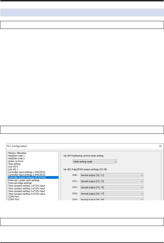
1.3.2 Selection of Positioning Control Mode
● The positioning control mode is selected in the system register no. 407 by the tool software.
(Note 1) If the compatible mode setting is set to “FP-X mode”, "Table setting mode" cannot be selected.
1.3.3 Comparison of Two Control Modes
There are following differences between the table setting mode and FP-X compatible instruction mode.
1-8 |
WUME-FPXHPOSG-01 |

1.3Comparison of Pulse Output Function
■Comparison of Two Control modes
Item |
|
Table setting mode |
FP-X compatible instruction mode |
|
|
Type |
Four patterns (System stop, Emergency |
Emergency stop only |
|
|
stop, Limit stop, and Deceleration stop) |
|||
|
|
|
||
Stop control |
|
|
|
|
|
Turns ON the output contact allocated to |
Turns ON the bit 3 of the special data |
||
|
|
|||
|
Start |
register DT90052 using F0 instruction in a |
||
|
each axis for each stop method. |
|||
|
|
user program. |
||
|
|
|
||
|
|
|
|
|
JOG |
Set |
Set in the positioning parameters of |
Set using the operands of instructions. |
|
Configurator PMX. |
||||
|
|
|||
operation |
|
|
|
|
Start |
F381 instruction |
F172 instruction |
||
|
||||
|
|
|
|
|
|
Type |
Five patterns (DOG methods x 3, Home |
Two patterns (DOG method x 1, Home |
|
|
position method x 1, Data set method x 1) |
position method x 1) |
||
|
|
|||
|
|
|
|
|
Home return |
Set |
Set in the positioning parameters of |
Set using the operands of instructions. |
|
|
Configurator PMX. |
|||
|
|
|
||
|
|
|
|
|
|
Start |
F382 instruction |
F171 instruction |
|
|
|
|
|
|
|
|
Four patterns (E-point control, P-point |
E-point control (single-speed |
|
|
Type |
control, C-point control and J-point |
acceleration / deceleration), Multistep |
|
Positioning |
|
control) |
acceleration / deceleration control |
|
|
|
|
||
operation |
Set |
Set in the positioning data table of |
Set using the operands of instructions. |
|
|
Configurator PMX. |
|||
|
|
|
||
|
Start |
F380 instruction |
F171 instruction |
|
|
|
|
|
|
|
Type |
Three patterns (E-point control, P-point |
E-point control (single-speed |
|
Positioning |
control, C-point control) |
acceleration / deceleration) |
||
|
||||
|
|
|
||
operation |
Set |
Set in the positioning data table of |
Set using the operands of instructions. |
|
interpolation |
Configurator PMX. |
|||
|
|
|||
|
Start |
F380 instruction |
F175 instruction |
|
|
|
|
|
|
|
|
Dwell time setting, Repeat control |
|
|
Others |
|
(Positioning parameter setting) |
Data table control (F174 instruction) |
|
|
Multiple table simultaneous start (F383 |
|||
|
|
|
||
|
|
instruction) |
|
|
|
|
|
|
|
■ Comparison in programming |
|
|||
Item |
|
Table setting mode |
FP-X compatible instruction mode |
||
Read / Write |
|
Area |
Positioning memory |
Special data registers DT90392 to |
|
|
DT90407 |
||||
of elapsed |
|
|
|
||
|
|
|
|
||
value |
|
Execut |
F384 instruction (Read), F385 instruction |
F1 instruction (Both Read and Write) |
|
|
|
e |
(Write) |
||
|
|
|
|||
|
|
|
|
||
Confirmation of BUSY |
Input contacts X28 to X2D |
Special relays R911C to R9121 |
|||
state |
|
||||
|
|
|
|||
|
|
|
|
||
Confirmation of |
|
Input contacts X30 to X35 |
|
||
positioning completion |
Instead detects the fall of the above BUSY |
||||
|
|||||
Confirmation of home |
Input contacts X48 to X4D |
signal by a user program. |
|||
|
|||||
return completion |
|
||||
|
|
||||
|
|
|
|
|
|
|
|
|
Allocate arbitrary input contacts and turn |
Allocate arbitrary input contacts and turn |
|
Near home input |
ON the outputs Y70 to Y75 by user |
ON the bit4 of the special data register |
|||
|
|
|
programs. |
DT90052 by user programs. |
|
|
|
|
|
|
|
WUME-FPXHPOSG-01 |
1-9 |

(MEMO)
1-10 |
WUME-FPXHPOSG-01 |

2 |
Wiring |
|
|
|
|
|
|
2.1 |
Connections with Servo Motor Amplifier ............................................. |
2-2 |
|
2.1.1 |
Connection Example ........................................................................ |
2-2 |
|
2.1.2 |
Precautions on Connection .............................................................. |
2-3 |
|
2.2 |
Connection with Stepping Motor Driver .............................................. |
2-4 |
|
2.2.1 |
Precautions on Connection .............................................................. |
2-4 |
|
WUME-FPXHPOSG-01 |
2-1 |

2.1Connections with Servo Motor Amplifier
2.1Connections with Servo Motor Amplifier
2.1.1Connection Example
PLC
FP-XH C30T
Amplifier
MINAS A5 series
2kΩ
Y0
2kΩ
Y1
5.1kΩ
X4
Home input
COM
Y8
−
COM
Near home input 
5.6kΩ
X8
5.6kΩ
X9
5.6kΩ
XA
Near home sensor 
CCW limit sensor
CW limit sensor
50 FG
3PULS1
4PULS2
5SIGN1
6SIGN2
19 |
CZ |
13 |
GND |
25 |
GND |
7COM
30 CL
29 SRV-ON
27 GAIN
31 A-CLR
9POT
8 |
NOT |
35 |
S-RDY |
34 |
S-RDY− |
37 |
ALM |
36 |
ALM− |
39 |
INP |
38 |
INP− |
41 |
COM− |
220Ω
220Ω
4.7Ω
4.7Ω
4.7Ω
4.7Ω
4.7Ω
4.7Ω
Z phase output
Counter clear input
Servo ON input
Gain switch input
Alarm clear input
Servo ready output
Servo alarm output
GND 24V
(Note 1) The allocation of I/O numbers on the controller side depends on unit types.
2-2 |
WUME-FPXHPOSG-01 |
2.1 Connections with Servo Motor Amplifier
2.1.2 Precautions on Connection
■ Connections of various signals
Signal type |
Point |
|||
|
|
● |
Connect the output allocated to each channel and the command pulse input of |
|
Pulse command output |
|
servo amplifier. |
||
● |
Connect a resistor (2 kΩ) for limiting currents. |
|||
|
|
|||
|
|
● |
Use twisted-pair cables for the connection. |
|
|
|
|
|
|
|
|
● |
Connect the input allocated to each channel and the Z phase input of servo |
|
Home input |
|
amplifier. |
||
|
|
● |
Use twisted-pair cables for the connection. |
|
|
|
|
|
|
Near home input |
● |
Connect the near home sensor to an arbitrary input. |
||
● |
It will be valid when the outputs (Y70 to Y75) allocated to each channel in user |
|||
|
|
|
programs turn ON. |
|
|
|
|
|
|
CCW over limit input |
● |
Connect the over limit switches to arbitrary inputs. |
||
|
|
● |
It will be valid when the outputs (Y80 to Y8B) allocated to each channel in user |
|
CW over limit input |
||||
|
programs turn ON. |
|||
|
|
|
||
|
|
|
|
|
|
|
● |
Connect the output allocated to each channel and the counter clear input of servo |
|
Deviation counter clear |
|
amplifier. |
||
output |
● |
The length of a deviation counter clear signal is specified in the range of 1 to 100 |
||
|
|
|
ms in the “Parameter setting” dialog box of Configurator PMX. |
|
|
|
|
|
|
Servo ON output |
● |
Connect an arbitrary output of PLC to the servo ON input of servo amplifier. |
||
|
|
|
|
|
|
|
|
|
|
|
|
|
|
|
● Use twisted-pair cables for the connection between the output of the unit and servo amplifiers.
WUME-FPXHPOSG-01 |
2-3 |

2.2Connection with Stepping Motor Driver
2.2Connection with Stepping Motor Driver
2.2.1Precautions on Connection
■ Connections of various signals
Signal type |
Point |
|||
|
|
● |
Connect the output allocated to each channel and the command pulse input of |
|
|
|
|
motor driver. |
|
Pulse command output |
● |
Use twisted-pair cables for the connection. |
||
|
|
● |
Use a 24 V DC input for the input on the driver side. When the input interface of |
|
|
|
|
the driver is 5 V DC input, insert a resistor for limiting currents externally. |
|
|
|
|
|
|
Home input |
● |
Connect the input allocated to each channel and the home sensor. |
||
● |
Use twisted-pair cables for the connection. |
|||
|
|
|||
|
|
|
|
|
Near home input |
● |
Connect the near home sensor to an arbitrary input. |
||
● |
It will be valid when the outputs (Y70 to Y75) allocated to each channel in user |
|||
|
|
|
programs turn ON. |
|
|
|
|
|
|
CCW over limit input |
● |
Connect the over limit switches to arbitrary inputs. |
||
|
|
● |
It will be valid when the outputs (Y80 to Y8B) allocated to each channel in user |
|
CW over limit input |
||||
|
programs turn ON. |
|||
|
|
|
||
|
|
|
|
|
|
|
|
|
|
|
|
|
|
|
● Use twisted-pair cables for the connection between the output of the unit and motor driver.
2-4 |
WUME-FPXHPOSG-01 |

3Power ON and OFF, and Items to Check
3.1 |
Safety Circuit Design .......................................................................... |
3-2 |
|
3.2 |
Before Turning On the Power ............................................................. |
3-3 |
|
3.3 |
Procedure for Turning On the Power .................................................. |
3-4 |
|
3.3.1 |
Procedure for Turning On the Power ............................................... |
3-4 |
|
3.3.2 |
Procedure for Turning Off the Power ............................................... |
3-4 |
|
3.4 |
Confirming while the Power is ON ...................................................... |
3-5 |
|
3.4.1 |
Items to check after turning on the power ........................................ |
3-5 |
|
3.4.2 |
Checking the Installation of the External Safety Circuit ................... |
3-6 |
|
3.4.3 |
Checking the Safety Circuit Based on the Unit ................................ |
3-6 |
|
3.4.4 Checking the Operation of the Near Home Switch and Home |
3-6 |
||
|
|
Switch ............................................................................................... |
|
3.4.5 |
Checking Rotating and Moving Directions and Moving Distance .... |
3-7 |
|
WUME-FPXHPOSG-01 |
3-1 |
3.1Safety Circuit Design
3.1Safety Circuit Design
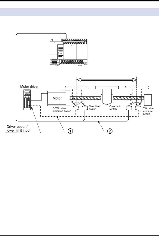
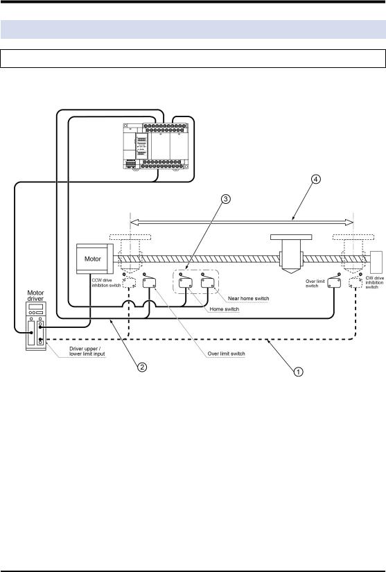
■ System configuration example
Installation of the over limit switch
■ |
Confirmation of safety circuit |
|||
|
|
|
|
|
No. |
|
Item |
Description |
|
(1) |
Safety circuit based on |
Install the safety circuit recommended by the manufacturer of the motor |
||
external circuit |
being used. |
|||
|
|
|||
|
|
|
|
|
(2) |
Safety circuit based on the |
Install over limit switches as shown above. |
||
Connect the over limit switch inputs on the (+) and (-) sides to the input |
||||
unit |
||||
|
|
circuit of PLC. |
||
|
|
|
||
|
|
|
|
|
3-2 |
WUME-FPXHPOSG-01 |
3.2 Before Turning On the Power
3.2 Before Turning On the Power
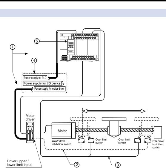
■ System configuration example
■ Items to check before turning ON the power
|
No. |
Item |
Description |
|
(1) |
Checking connections to the |
Check to make sure the various devices have been connected as |
|
various devices |
indicated by the design. |
|
|
|
||
|
|
|
|
|
(2) |
Checking the installation of |
Check to make sure the safety circuit (wiring and installation of over |
|
the external safety circuit |
limit switch) based on an external circuit has been installed securely. |
|
|
|
||
|
|
|
|
|
|
Checking the installation of |
Check the connection between the unit and over limit switches. Check |
|
(3) |
the safety circuit based on |
|
|
the installation condition of the over limit switches. |
||
|
|
the unit |
|
|
|
|
|
|
|
|
|
|
|
Checking the procedure |
Make sure settings have been entered so that power supplies will be |
|
(4) |
settings for turning ON the |
turned on according to the procedure outlined in section “Procedure for |
|
|
power supplies |
Turning ON the Power”. |
|
|
|
|
|
(5) |
Checking the Control Unit |
Set the Control Unit to PROG. mode. Setting it in the RUN mode can |
|
mode selection switch |
cause inadvertent operation. |
|
|
|
||
|
|
|
|
|
|
|
|
WUME-FPXHPOSG-01 |
3-3 |
3.3Procedure for Turning On the Power
3.3Procedure for Turning On the Power
3.3.1Procedure for Turning On the Power
When turning on the power to the system incorporating the unit, consider the nature and states of any external devices connected to the system, and take sufficient care so that turning on the power will not initiate unexpected movements.
1.Turn on the power supplies for the input and output devices connected to the PLC.
2.Turn ON the power supply for the PLC.
3.Turn ON the power supply for the motor driver.
3.3.2 Procedure for Turning Off the Power
1.Check to make sure the rotation of the motor has stopped, and then turn OFF the power supply for the motor driver.
2.Turn off the power supply for the PLC.
3.Turn off the power supplies for the input and output devices connected to the PLC.
3-4 |
WUME-FPXHPOSG-01 |
3.4 Confirming while the Power is ON
3.4 Confirming while the Power is ON
3.4.1 Items to check after turning on the power
■ System configuration example
Check each item in the following four major steps.
■ Items to check before turning ON the power
No. |
Item |
Description |
|
(1) |
Checking the installation of |
Check to make sure the safety circuit (wiring and installation of over |
|
the external safety circuit |
limit switch) based on an external circuit has been installed securely. |
||
|
|||
|
|
|
|
(2) |
Checking the safety circuit |
Check the connection between the unit and over limit switches. Check |
|
by the PLC unit |
the installation condition of the over limit switches. |
||
|
|||
|
|
|
|
|
Checking the near home |
Check if the near home input and home input are loaded as the inputs |
|
(3) |
of the PLC and activated properly by performing JOG operation or |
||
input and home input |
|||
|
home return operation. |
||
|
|
||
|
|
|
|
|
Checking the rotation, |
Check the rotation, moving direction and moving distance by |
|
(4) |
moving direction, and |
||
performing JOG operation or positioning operation. |
|||
|
moving distance. |
||
|
|
||
|
|
|
WUME-FPXHPOSG-01 |
3-5 |
3.4Confirming while the Power is ON
3.4.2Checking the Installation of the External Safety Circuit
Make a check on the safety circuit recommended by the motor manufacturer, which includes a check on the disconnection of the power supply to the motor driver with CW and CCW drive inhibition switch input from an external circuit.
3.4.3 Checking the Safety Circuit Based on the Unit
1.Using forced operation of the over limit switch, check to see if the over limit input is being properly taken into the PLC side.
2.If necessary, input a program to start the JOG operation. Then operate the over limit input to check whether the motor will stop. The limit stop will be effective when output signals (Y80 to Y8B) allocated to each axis turn ON in user programs. In addition, the valid logic of over limit input can be changed in the parameter setting menu of "Configurator PMX".
3.Using the JOG operation, check to see if the over limit switch is functioning properly.
Operation at over limit input
Conditions |
Direction |
Limit status |
Operation |
|
|
Forward |
Over limit input (+): ON |
Not executable, Error occurs. |
|
|
|
|
||
When JOG operation is |
Over limit input (-): ON |
Executable |
||
|
||||
started |
|
|
|
|
Reverse |
Over limit input (+): ON |
Executable |
||
|
||||
|
|
|
||
|
Over limit input (-): ON |
Not executable, Error occurs. |
||
|
|
|||
|
|
|
|
|
|
Forward |
Over limit input (+): ON |
Limit stops, Error occurs. |
|
|
|
|
||
During JOG operation |
Over limit input (-): ON |
Limit stops, Error occurs. |
||
|
||||
|
|
|
||
Reverse |
Over limit input (+): ON |
Limit stops, Error occurs. |
||
|
||||
|
|
|
||
|
Over limit input (-): ON |
Limit stops, Error occurs. |
||
|
|
|||
|
|
|
|
3.4.4 Checking the Operation of the Near Home Switch and Home Switch
1.Check if the near home input is loaded as input signals on the PLC properly by operating the home input and near home input forcibly.
2.Start the home return by inputting the home return program, and check if the operation transits to the deceleration operation by the near home input.
Points to check
Set the valid logic which enables the home input and near home input in the parameter setting menu of "Configurator PMX".
3-6 |
WUME-FPXHPOSG-01 |

3.4 Confirming while the Power is ON
3.Check if the home stop position shifts by repeating the JOG and home return operations.
Points to check
A shift may result depending on the position of near home input or home input and the return speed.
4.If the home stopping position is shifted, change the position of near home input or reduce the home return speed.
3.4.5 Checking Rotating and Moving Directions and Moving Distance
1.Execute the JOG operation to confirm the rotating direction and moving direction of the motor.
Points to check
The rotating direction is determined according to the installation of the ball screw or the “CW/CCW direction setting” of the parameter.
2.Check if the moving distance is that as designed by performing the JOG operation or positioning operation.
Points to check
The moving distance is determined according to the pitch of the ball screw, deceleration gear ratio or setting movement amount of the positioning data.
WUME-FPXHPOSG-01 |
3-7 |

(MEMO)
3-8 |
WUME-FPXHPOSG-01 |
 Loading...