

Panasonic FP-XH User Manual

Programmable Controller
FP-XH Series
User’s Manual
Basic
Western version
WUME-FPXHBASG-01
2020.10
panasonic.net/id/pidsx

(MEMO)
2 WUME-FPXHBASG-01

Introduction
Thank you for purchasing a Panasonic product. Before you use the product, please carefully
read through the user’s manual, and understand it in detail to use the product properly.
Types of Manuals
● The following user’s manuals are available for the FP-XH series. Please refer to a relevant
manual for the unit and purpose of your use.
● The manuals can be downloaded from our Download Center:https://
industrial.panasonic.com/ac/e/dl_center/.
Unit name or purpose of
use
FP-XH Control Unit
Positioning Function /
PWM Output / High-speed
Counter Function
Communication Functions
FP-X Extension
(Communication) Cassette
FP-X Expansion Unit
FP-X Function Cassettes
Manual name Manual code
FP-XH User‘s Manual (Basic) WUME-FPXHBASG
FP Series Programming Manual ARCT1F313E
FP-XH User’s Manual
(Positioning / PWM Output / High-speed Counter)
FP-XH User‘s Manual (COM Communication) WUME-FPXHCOMG
FP-X Series User’s Manual WUME-FPX
WUME-FPXHPOSG
WUME-FPXHBASG-01 iii
SAFETY PRECAUTIONS
● To prevent accidents or personal injuries, please be sure to comply with the following items.
● Prior to installation, operation, maintenance and inspection, please read this manual carefully for proper use.
● Before using the product, please fully understand the knowledge related to the equipment, safety
precautions and all other precautions.
● Safety precautions are divided into two levels in this manual: Warning and Caution.
Incorrect operation may lead to death or serious injury.
● Take appropriate safety measures for the external circuit of the product to ensure the security of the whole
system in case of abnormalities caused by product failure or external factors.
● Do not use this product in areas with inflammable gases.
Otherwise it may lead to an explosion.
● Do not put this product into a fire.
Otherwise it may cause damage to the battery or other electronic parts.
● Do not impact, charge or heat the lithium battery, and do not put it into a fire.
Otherwise it may lead to fire or damage.
Incorrect operation may lead to injury or material loss.
● To prevent the excessive exothermic heat or smoke generation of the product, a certain margin is required
for guaranteed characteristics and performance ratings of relative products.
● Do not disassemble or modify the product.
Otherwise it may lead to the excessive exothermic heat or smoke generation of the product.
● Do not touch terminal blocks during power-on.
Otherwise it may result in an electric shock.
● Create an emergency stop and interlock circuit in the external devices.
● Connect wires and connectors reliably.
Otherwise it may lead to the excessive exothermic heat or smoke generation of the product.
● Do not carry out construction (wiring, removal, etc.) during power-on.
Otherwise it may result in an electric shock.
● If the equipment is used in a manner not specified by the Panasonic, the protection provided by the
equipment may be impaired.
● This product has been developed/produced for industrial use only.
Description on Copyright and Trademarks
● The copyright of this manual is owned by Panasonic Industrial Devices SUNX Co., Ltd
● Unauthorized reproduction of this manual is strictly prohibited.
● Windows is a registered trademark of Microsoft Corporation in the U.S. and other countries.
● Ethernet is a registered trademark of Fuji Xerox Co., Ltd. and Xerox Corporation.
● Other company and product names are trademarks or registered trademarks of their respective companies.
Compatibility with the conventional FP-X series
The FP-XH series is upward compatible with a conventional FP-X Control Unit. However, be
careful with the following points.
■
Hardware compatibility
● The FP-XH series can be used in combination with FP-X Expansion Units.
iv
WUME-FPXHBASG-01

● The FP-X Extension Cassette (Communication Cassette) and FP-X Extension Cassette
(Function Cassette) can also be used. With the FP-XH Control Unit, there are less
restrictions on the installation position.
● The wiring for the transistor type Control Unit is different. The external power supply (24 V
DC) for driving the output circuit is not necessary.
● The backup battery type is different. A special battery for the FP-XH series is required.
● The port for connecting to a personal computer is USB 2.0 (miniB type).
■
Software compatibility
● The positioning function has been largely improved. A table setting mode has been added to
facilitate simplified setting and programming. In addition, position control patterns and home
return patterns have been added.
● For using the projects (programs, comments and system registers) created for the
conventional FP-X, the projects must be converted to the projects for the FP-XH using the
“Convert PLC Type” function of the tool software.
● All the instructions for the conventional FP-X are supported.
Instruction Section Main differences in specifications
SYS1
F12 (ICRD) F-ROM reading
P13 (PICWT) F-ROM writing
F145 (SEND) Data send instruction
F146 (RECV) Data receive instruction
F172 (PLSH)
F173 (PWMH) PWM output instructions Parameter settings are simplified.
F380 (POSST) Positioning table start
F381 (JOGST) JOG operation start
F382 (ORGST) Home return start
F383 (MPOST)
F384 (PTBLR)
F385 (PTBLW)
Communication condition
settings
Pulse output (JOG
operation) instruction
Positioning table
simultaneous start
Reading positioning
parameters
Writing positioning
parameters
The ranges that can be specified for the port number and
baud rate are extended.
The range for the block number to be specified when an
instruction is executed is extended.
The range for the COM port number to be specified when the
MEWTOCOL master or MODBUS master is sent is extended.
The characteristic of the acceleration / deceleration zone are
different.
Added for the positioning function (table setting mode).
WUME-FPXHBASG-01 v

(MEMO)
vi WUME-FPXHBASG-01

Table of Contents
1 System Configuration...........................................................................1-1
1.1 List of Units .........................................................................................1-2
1.1.1 FP-XH Control Units ........................................................................ 1-2
1.1.2 FP-X Expansion Units...................................................................... 1-2
1.1.3 FP-X Expansion FP0 Adapter.......................................................... 1-3
1.1.4 FP-X Extension Cassettes (Communication Cassettes).................. 1-3
1.1.5 FP-X Extension Cassettes (Function Cassettes)............................. 1-4
1.2 List of Unit Model Numbers.................................................................1-5
1.2.1 FP-XH Control Units ........................................................................ 1-5
1.2.2 FP-X Expansion Units...................................................................... 1-5
1.2.3 FP-X Expansion FP0 Adapter.......................................................... 1-6
1.2.4 FP-X Extension Cassettes (Communication Cassettes).................. 1-6
1.2.5 FP-X Extension Cassettes (Function Cassettes)............................. 1-6
1.2.6 Options............................................................................................. 1-7
1.2.7 Maintenance Parts ........................................................................... 1-7
1.3 Restrictions on Combinations of Units................................................1-8
1.3.1 Restrictions on Using FP-X Expansion Units................................... 1-8
1.3.2 Restrictions on Using FP-X Expansion FP0 Adapter....................... 1-9
1.3.3 Restrictions on Combinations of Extension Cassettes .................... 1-10
1.3.4 Restrictions on Communication Functions....................................... 1-12
1.3.5 Restrictions on Combined Use of Functions.................................... 1-13
1.4 Programming Tools.............................................................................1-14
1.4.1 Software Usage Environment and Applicable Cables ..................... 1-14
1.4.2 Applicable software version ............................................................. 1-14
2 Control Unit Specifications..................................................................2-1
2.1 Names and Functions of Parts............................................................2-2
2.1.1 Names and Functions of Parts......................................................... 2-2
2.1.2 Specifications of Operation Indicator LEDs ..................................... 2-3
2.1.3 Specifications of COM0 Port............................................................ 2-4
2.2 Power Supply Specifications...............................................................2-5
2.2.1 AC Power Supply Type.................................................................... 2-5
2.2.2 AC Power Supply Type: Service Power Supply for Input Circuit ..... 2-5
2.2.3 DC Power Supply Type.................................................................... 2-6
2.3 Input and Output Specifications (Relay Output Type).........................2-7
2.3.1 Input Specifications.......................................................................... 2-7
2.3.2 Output Specifications ....................................................................... 2-8
2.4 Input and Output Specifications (Transistor Output Type) ..................2-9
2.4.1 Input Specifications.......................................................................... 2-9
2.4.2 Output Specifications ....................................................................... 2-10
2.5 Terminal Layout...................................................................................2-11
2.5.1 Relay Output (AC Power Supply Type)............................................ 2-11
2.5.2 Relay Output (DC Power Supply Type) ........................................... 2-12
2.5.3 Transistor Output (AC Power Supply Type) ..................................... 2-13
2.5.4 Transistor Output (DC Power Supply Type)..................................... 2-15
WUME-FPXHBASG-01
vii

3 Allocation of I/O Numbers....................................................................3-1
3.1 Basics of I/O Allocation.......................................................................3-2
3.1.1 How to Count I/O Numbers.............................................................. 3-2
3.1.2 Concept of I/O Number Allocation ................................................... 3-2
3.2 List of I/O Numbers for Each Unit .......................................................3-4
3.2.1 FP-XH Control Units ........................................................................ 3-4
3.2.2 FP-X Expansion Units...................................................................... 3-4
3.2.3 FP-X Function Cassettes ................................................................. 3-4
3.3 Allocation of FP0 Expansion Units......................................................3-6
3.3.1 Concept of I/O Number Allocation ................................................... 3-6
3.3.2 Types and I/O Numbers of FP0R Expansion Units.......................... 3-7
3.3.3 Types and I/O Numbers of FP0 Expansion Units ............................ 3-8
4 Installation and Wiring..........................................................................4-1
4.1 Installation...........................................................................................4-3
4.1.1 Installation Environment and Space ................................................ 4-3
4.2 Installation of Backup Battery .............................................................4-5
4.2.1 Installation of Backup Battery .......................................................... 4-5
4.3 Installation of Extension Cassette.......................................................4-6
4.3.1 Precautions When Installing the Extension Cassette ...................... 4-6
4.3.2 Installing the Communication Cassette............................................ 4-6
4.3.3 Installing the Function Cassette....................................................... 4-7
4.4 Connection of FP-X Expansion Unit ...................................................4-8
4.4.1 Setting of the Terminator Setting Switch .......................................... 4-8
4.4.2 Checking FP-X Expansion Cable..................................................... 4-8
4.4.3 Connection of FP-X Expansion Unit ................................................ 4-8
4.5 Connection of FP0 Expansion Unit.....................................................4-10
4.5.1 Connection of FP0 Expansion Unit .................................................. 4-10
4.5.2 Connection of FP-X Expansion FP0 Adapter................................... 4-10
4.6 Installation...........................................................................................4-12
4.6.1 Attachment to DIN Rail and Removal from DIN Rail........................ 4-12
4.6.2 Installation with screws .................................................................... 4-13
4.7 Wiring the Power Supply.....................................................................4-14
4.7.1 Common Precautions ...................................................................... 4-14
4.7.2 Grounding ........................................................................................ 4-14
4.7.3 Power Supply of Control Unit / Expansion Unit................................ 4-15
4.7.4 Power Supply of FP-X Expansion FP0 Adapter / FP0 Expansion
Unit.................................................................................................... 4-17
4.8 Wiring of Input and Output..................................................................4-19
4.8.1 Precautions on Wirings of Input and Output .................................... 4-19
4.8.2 Service Power Supply for Input and Output (Control Unit and
Expansion Unit: E30) ........................................................................ 4-19
4.8.3 Input Wiring...................................................................................... 4-19
4.8.4 Output Wiring ................................................................................... 4-21
4.9 Wiring the Terminal Block ...................................................................4-22
4.9.1 Suitable wires................................................................................... 4-22
4.9.2 Terminal block covers ...................................................................... 4-22
4.9.3 Installing / Removing the Terminal Block (C30 / C60)...................... 4-23
viii
WUME-FPXHBASG-01

4.10 Safety Measures...............................................................................4-25
4.10.1 Safety Measures ............................................................................ 4-25
4.10.2 Instantaneous Power Failure ......................................................... 4-25
4.10.3 Watchdog Timer ............................................................................. 4-26
5 Procedures Before Starting Operation ...............................................5-1
5.1 Before Turning On the Power .............................................................5-2
5.1.1 Check Items ..................................................................................... 5-2
5.1.2 Procedures Before Starting Operation............................................. 5-2
5.2 Offline Edit of Program........................................................................5-4
5.2.1 Elements of Program ....................................................................... 5-4
5.2.2 System Register Settings................................................................. 5-4
5.2.3 Setting of Positioning Parameters.................................................... 5-5
5.3 Program Download and Operation .....................................................5-6
5.3.1 Before Turning ON the Power.......................................................... 5-6
5.3.2 Program Download and Mode Switching......................................... 5-6
5.3.3 Totally Checking Project................................................................... 5-9
5.3.4 Verifying Project............................................................................... 5-9
5.4 Online Edit ..........................................................................................5-13
5.4.1 Overview of Online Edit ................................................................... 5-13
5.4.2 Online Edit of Program..................................................................... 5-13
5.4.3 Online Edit of System Register ........................................................ 5-14
5.5 Program Block ....................................................................................5-16
5.5.1 Overview of Program Block ............................................................. 5-16
5.5.2 Changing the Execution Order of Program Blocks .......................... 5-16
6 Memory / Master Memory Cassette.....................................................6-1
6.1 Memory Backup..................................................................................6-2
6.1.1 Backup of Program Memory ............................................................ 6-2
6.1.2 Backup of Operation Memory .......................................................... 6-2
6.1.3 Backup of Operation Memory (With Battery) ................................... 6-3
6.1.4 Settings of Battery Error Alarm and Hold Area ................................ 6-4
6.2 RAM / ROM Transfer Function ...........................................................6-6
6.2.1 Overview of Functions ..................................................................... 6-6
6.2.2 Operation Using Tool Software ........................................................ 6-6
6.3 Function of Master Memory Cassette.................................................6-7
6.3.1 Overview of Functions ..................................................................... 6-7
6.3.2 Settings of Master Memory Unit....................................................... 6-7
6.4 Master Memory Function ....................................................................6-8
6.4.1 Overview of Functions ..................................................................... 6-8
6.4.2 Before Turning ON the Power.......................................................... 6-8
6.4.3 Data Transfer to Master Memory Cassette...................................... 6-9
6.4.4 Data Transfer from Master Memory Cassette to Control Unit.......... 6-11
6.4.5 Using Master Memory Cassette with Other Models......................... 6-13
6.5 Clock / calendar ..................................................................................6-14
6.5.1 Overview of Functions ..................................................................... 6-14
6.5.2 Clock / calendar Setting ................................................................... 6-14
6.5.3 Application Example of Clock / calendar.......................................... 6-15
WUME-FPXHBASG-01
ix

7 Security Function..................................................................................7-1
7.1 Password Protect Function.................................................................7-2
7.1.1 Overview of Functions ..................................................................... 7-2
7.1.2 Setting with tool software ................................................................. 7-2
7.2 Program Upload Protection Function..................................................7-9
7.2.1 Overview of Functions ..................................................................... 7-9
7.2.2 Configuration.................................................................................... 7-9
7.3 Availability of Security Function ..........................................................7-11
7.3.1 Control Unit ...................................................................................... 7-11
8 Other Functions ....................................................................................8-1
8.1 Analog Potentiometer .........................................................................8-2
8.1.1 Overview of Functions ..................................................................... 8-2
8.1.2 Example Showing How to Use Analog Potentiometer ..................... 8-2
8.2 Input Time Constant Setting Function.................................................8-3
8.2.1 Overview of functions....................................................................... 8-3
9 Troubleshooting....................................................................................9-1
9.1 Self-diagnosis function........................................................................9-2
9.1.1 Operation Monitor LEDs of Control Unit .......................................... 9-2
9.1.2 Operation Monitor LEDs of FP-X Expansion FP0 Adapter .............. 9-2
9.1.3 Operation Mode When an Error Occurs .......................................... 9-3
9.2 What to Do If an Error Occurs.............................................................9-5
9.2.1 ERR. LED Flashes........................................................................... 9-5
9.2.2 Mode does Not Change to RUN Mode ............................................ 9-6
9.2.3 ERR. LED Lights.............................................................................. 9-6
9.2.4 ALL LEDs are OFF .......................................................................... 9-7
9.2.5 A Protect Error Message Appears ................................................... 9-7
9.2.6 Diagnosing Output Malfunction........................................................ 9-8
9.2.7 Expansion Unit does not Operate .................................................... 9-9
9.2.8 Communication Error Occurs (RS-232C) ........................................ 9-9
9.2.9 Communication Error Occurs (RS-422) ........................................... 9-10
9.2.10 Communication Error Occurs (RS-485) ......................................... 9-11
9.2.11 Communication Error Occurs (Ethernet) ........................................ 9-11
10 Maintenance and Inspection..............................................................10-1
10.1 Handling of Backup Battery ..............................................................10-2
10.1.1 Replacement of Backup Battery .................................................... 10-2
10.1.2 Lifetime and Time for Replacement of Backup Battery.................. 10-3
10.2 Inspection..........................................................................................10-4
11 Specifications......................................................................................11-1
11.1 Control Unit Specifications ................................................................11-2
11.1.1 General Specifications ................................................................... 11-2
11.1.2 Performance Specifications............................................................ 11-3
11.2 Communication Function Specifications ...........................................11-7
11.2.1 Communication Specifications of Control Unit ............................... 11-7
11.2.2 Communication Cassette Specifications ........................................ 11-7
x
WUME-FPXHBASG-01

11.3 Operation Memory Area....................................................................11-10
11.4 List of System Registers ...................................................................11-12
11.4.1 List of System Registers................................................................. 11-12
11.5 List of Special Relays........................................................................11-24
11.6 List of Special Data Registers ...........................................................11-38
11.7 List of Error Codes ............................................................................11-55
11.7.1 List of Syntax Check Errors............................................................ 11-55
11.7.2 Self-diagnostic Errors ..................................................................... 11-56
11.7.3 List of MEWTOCOL-COM Communication Error Codes................ 11-57
11.8 Dimensions .......................................................................................11-59
11.8.1 External Dimensions ...................................................................... 11-59
11.8.2 Mounting Dimensions..................................................................... 11-60
WUME-FPXHBASG-01 xi

(MEMO)
xii WUME-FPXHBASG-01

1 System Configuration
1.1 List of Units .........................................................................................1-2
1.1.1 FP-XH Control Units ........................................................................ 1-2
1.1.2 FP-X Expansion Units...................................................................... 1-2
1.1.3 FP-X Expansion FP0 Adapter.......................................................... 1-3
1.1.4 FP-X Extension Cassettes (Communication Cassettes).................. 1-3
1.1.5 FP-X Extension Cassettes (Function Cassettes)............................. 1-4
1.2 List of Unit Model Numbers.................................................................1-5
1.2.1 FP-XH Control Units ........................................................................ 1-5
1.2.2 FP-X Expansion Units...................................................................... 1-5
1.2.3 FP-X Expansion FP0 Adapter.......................................................... 1-6
1.2.4 FP-X Extension Cassettes (Communication Cassettes).................. 1-6
1.2.5 FP-X Extension Cassettes (Function Cassettes)............................. 1-6
1.2.6 Options............................................................................................. 1-7
1.2.7 Maintenance Parts ........................................................................... 1-7
1.3 Restrictions on Combinations of Units................................................1-8
1.3.1 Restrictions on Using FP-X Expansion Units................................... 1-8
1.3.2 Restrictions on Using FP-X Expansion FP0 Adapter....................... 1-9
1.3.3 Restrictions on Combinations of Extension Cassettes .................... 1-10
1.3.4 Restrictions on Communication Functions....................................... 1-12
1.3.5 Restrictions on Combined Use of Functions.................................... 1-13
1.4 Programming Tools.............................................................................1-14
1.4.1 Software Usage Environment and Applicable Cables ..................... 1-14
1.4.2 Applicable software version ............................................................. 1-14
WUME-FPXHBASG-01
1-1
1.1 List of Units
1.1 List of Units
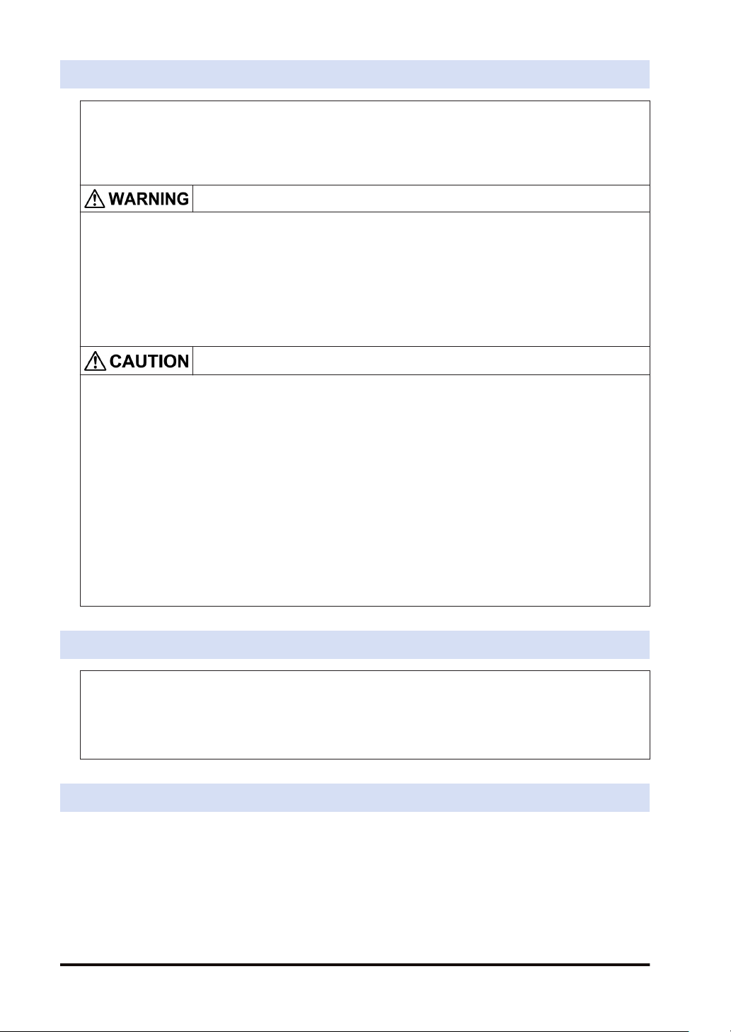
1.1.1 FP-XH Control Units
The following types are available depending on the number of points, power supply, and output
type.
Number of points 14 points / 30 points / 60 points
Power supply 100 to 240 V AC or 24 V DC
Output Relay or transistor (NPN output)
1.1.2 FP-X Expansion Units
The following types are available depending on the number of points, power supply, and output
type.
■
FP-X Expansion Units
Number of
points
Power supply No power supply 100 to 240 V AC or 24 V DC
Output Relay or transistor (NPN output or PNP output)
14 points (for output only) / 16 points (for input
only) / 16 (8/8) points
30 (16/14) points
1-2 WUME-FPXHBASG-01
1.1 List of Units
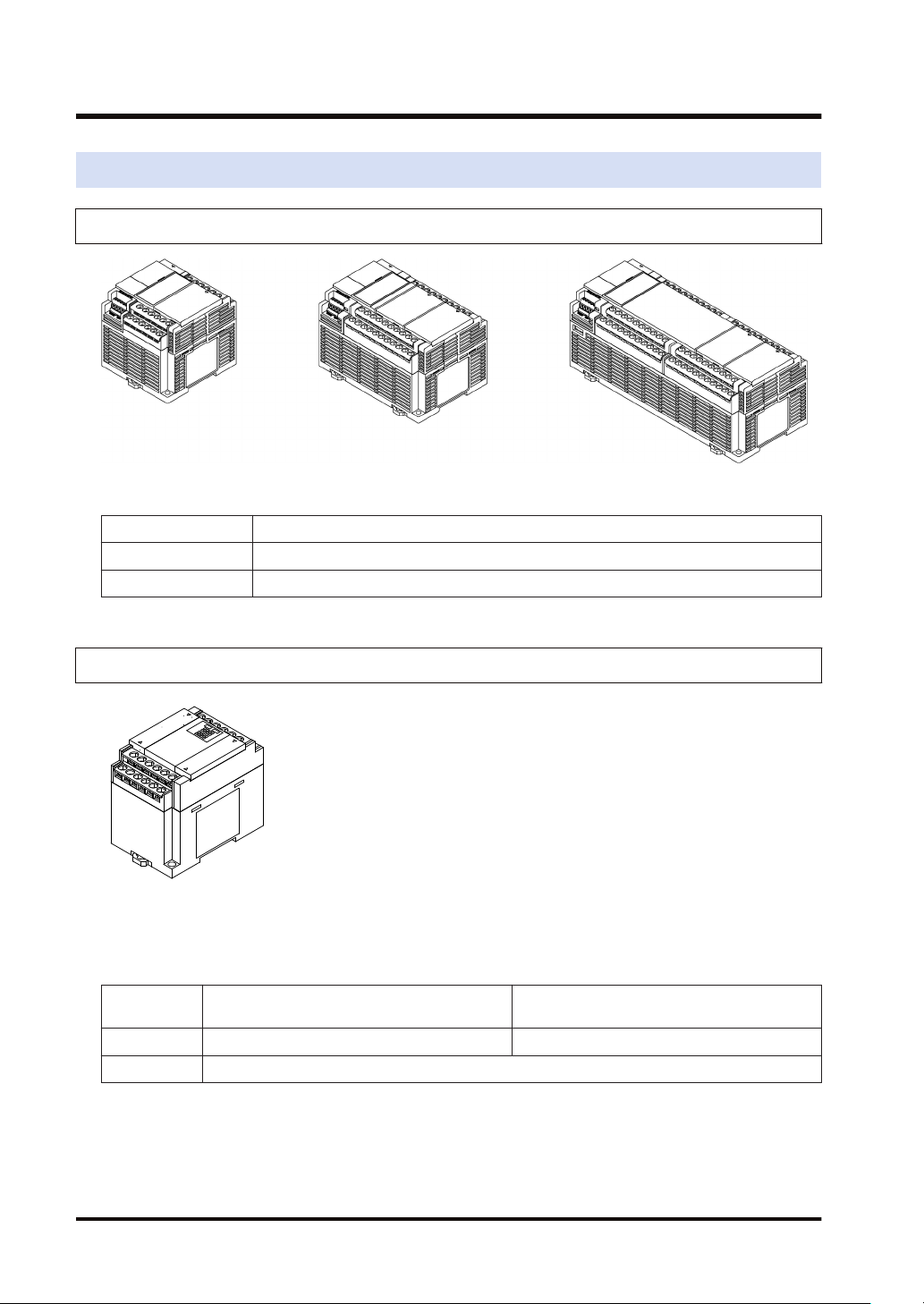
1.1.3 FP-X Expansion FP0 Adapter
The FP-X Expansion FP0 Adapter is an interface adapter that can be connected to the FP0
Series Expansion Unit / Intelligent Unit.
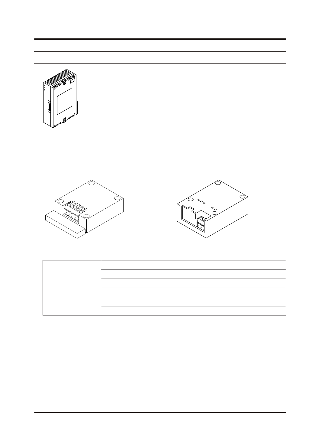
1.1.4 FP-X Extension Cassettes (Communication Cassettes)
The following types are available depending on the type of communication interface or the
number of channels.
RS-232C (5-wire type) x 1 channel
RS-232C (3-wire type) x 2 channels
Communication method
WUME-FPXHBASG-01 1-3
RS-485 / RS-422 x 1 channel
RS-485 x 1 channel + RS-232C (3-wire type) x 1 channel
RS-485 x 2 channels
Ethernet x 1 channel + RS-232C (3-wire type) x 1 channel
1.1 List of Units
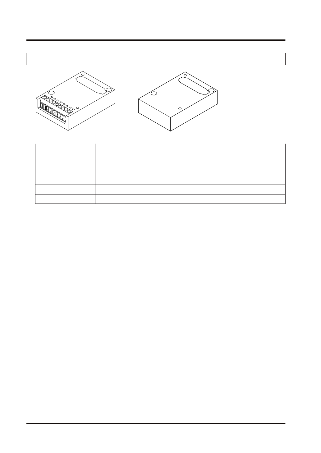
1.1.5 FP-X Extension Cassettes (Function Cassettes)
The following types are available depending on the output type and function.
Analog input x 2 channels
Analog I/O
Digital I/O
Pulse I/O High-speed counter × 2 channels + pulse output × 1 channel
Master memory Master memory + real-time clock
Analog output x 2 channels
Analog input x 2 channels + analog output x 1 channel
8-point input, 8-point transistor output
4-point input + 3-point transistor output
1-4 WUME-FPXHBASG-01
1.2 List of Unit Model Numbers
1.2.1 FP-XH Control Units
1.2 List of Unit Model Numbers
Item name
FP-XH C14R
Control Unit
FP-XH C14T
Control Unit
FP-XH C30R
Control Unit
FP-XH C30T
Control Unit
FP-XH C60R
Control Unit
FP-XH C60T
Control Unit
Input and output specifications Power supply
8-point DC input, 6-point relay output
8-point DC input, 6-point transistor output
(NPN)
16-point DC input, 14-point relay output
16-point DC input, transistor output (NPN)
32-point DC input, 28-point relay output
32-point DC input, 28-point transistor output
(NPN)
Specifications
1.2.2 FP-X Expansion Units
Item name
Input and output specifications Power supply
8-point DC input, 8-point relay output - AFPX-E16R
FP-X E16
Expansion I/O Unit
8-point DC input, 8-point transistor output
(NPN)
8-point DC input, 8-point transistor output
(PNP)
16-point DC input, 14-point relay output
FP-X E30
Expansion I/O Unit
16-point DC input, 14-point transistor output
(NPN)
16-point DC input, 14-point transistor output
(PNP)
FP-X E16
Expansion Input Unit
FP-X E14R
Expansion Output Unit
(Note 1) An 8 cm expansion cable is provided with the Expansion Unit.
16-point DC input - AFPX-E16X
14-Point relay output - AFPX-E14YR
Specifications
Product no.
100 to 240 V AC AFPXHC14R
24 V DC AFPXHC14RD
100 to 240 V AC AFPXHC14T
24 V DC AFPXHC14TD
100 to 240 V AC AFPXHC30R
24 V DC AFPXHC30RD
100 to 240 V AC AFPXHC30T
24 V DC AFPXHC30TD
100 to 240 V AC AFPXHC60R
24 V DC AFPXHC60RD
100 to 240 V AC AFPXHC60T
24 V DC AFPXHC60TD
Product no.
- AFPX-E16T
- AFPX-E16P
100 to 240 V AC AFPX-E30R
24 V DC AFPX-E30RD
100 to 240 V AC AFPX-E30T
24 V DC AFPX-E30TD
100 to 240 V AC AFPX-E30P
24 V DC AFPX-E30PD
WUME-FPXHBASG-01 1-5

1.2 List of Unit Model Numbers
1.2.3 FP-X Expansion FP0 Adapter
Name Specifications Product no.
FP-X Expansion FP0
Adapter
(Note 1) An 8 cm expansion cable is provided with the Expansion Unit.
1.2.4 FP-X Extension Cassettes (Communication Cassettes)
Name Specifications Product no.
FP-X Communication
Cassette
For connecting the FP0 Expansion Unit AFPX-EFP0
5-wire RS-232C x 1 channel AFPX-COM1
3-wire RS-232C x 2 channels AFPX-COM2
RS-485 / RS-422 (isolated) x 1 channel AFPX-COM3
RS-485 (isolated) x 1 channel + 3-wire RS-232C x 1 channel AFPX-COM4
RS-485 (isolated) x 2 channels (non-isolated between channels) AFPX-COM6
Ethernet port + 3-wire RS-232C x 1 channel AFPX-COM5
1.2.5 FP-X Extension Cassettes (Function Cassettes)
Name Specifications Product no.
FP-X Analog Input
Cassette
FP-X Analog Output
Cassette
Analog
FP-X Analog I/O Cassette
I/O
FP-X Thermocouple
Cassette
FP-X Resistance
Thermometer Cassette
FP-X Input Cassette 8-point DC input AFPX-IN8
Digital
I/O
FP-X Output Cassette 8-point transistor output (NPN) AFPX-TR8
FP-X Output Cassette 6-point transistor output (PNP) AFPX-TR6P
FP-X I/O Cassette
FP-X Pulse I/O Cassette
FP-X Master Memory Cassette Master memory + real-time clock AFPX-MRTC
Analog input (non-isolated) x 2 channels AFPX-AD2
Analog output (isolated) x 2 channels
(isolated between channels)
AFPX-DA2
Analog input (isolated) x 2 channels
(non-isolated between channels)
AFPX-A21
+ Analog output (isolated) x 1 channel
Thermocouple input (isolated) x 2 channels
(isolated between channels)
AFPX-TC2
Resistance thermometer input (isolated) x 2
channels
AFPX-RTD2
(isolated between channels)
4-point DC input + 3-point transistor output
(NPN)
High-speed counter × 2 channels + pulse
output × 1 channel
AFPX-IN4T3
AFPX-PLS
1-6 WUME-FPXHBASG-01
1.2.6 Options
Name Specifications Product no.
FP-XH Backup Battery
FP-X terminal block (C30/
C60)
1.2.7 Maintenance Parts
FP-X Expansion
Cable
1.2 List of Unit Model Numbers
Required when expanding the hold area of the operation
memory or when using the clock / calendar function.
For C30/C60 control unit for E30 expansion I/O unit with 21-pin
cover (no printing) 4 pcs/pack
Name Specifications Product no.
8 cm AFPX-EC08
30 cm AFPX-EC30
(Note 1)(Note 2)
80 cm AFPX-EC80
AFPABAT001
AFPX-TAN1
FP0
Power supply cable
(Note 1) An 8 cm expansion cable (AFPX-EC08) is provided with the FP-X Expansion Unit or with the FP-X
For the Expansion FP0 Adapter, length:
1 m
AFP0581
Expansion FP0 Adapter. The total length of the expansion cable should be within 160 cm.
(Note 2) If a longer expansion cable is used, an I/O check error may occur due to noise, etc. In such a case, it
is recommended that measures such as installing a ferrite core be taken.
WUME-FPXHBASG-01 1-7
1.3 Restrictions on Combinations of Units
1.3 Restrictions on Combinations of Units
1.3.1 Restrictions on Using FP-X Expansion Units
■
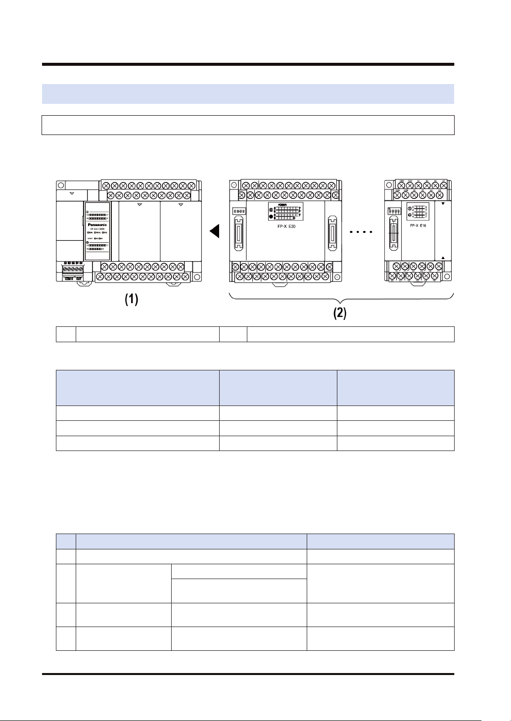
Restrictions on the number of Expansion Units and mounting order (1)
● Up to 8 Expansion Units can be connected.
(1) FP-XH Control Units (2) FP-X Expansion Units
■
Maximum number of control inputs / outputs
Control unit
Type of Control Unit
FP-XH C14 Control Unit 14 points Max. 254 points
FP-XH C30 Control Unit 30 points Max. 270 points
FP-XH C60 Control Unit 60 points Max. 300 points
■
Restrictions on combinations of Expansion Cables
No. of inputs / outputs of a
single control unit
FP-X-E30
No. of inputs / outputs when
using Expansion Units
● The total length of the expansion cables should be within 160 cm.
■
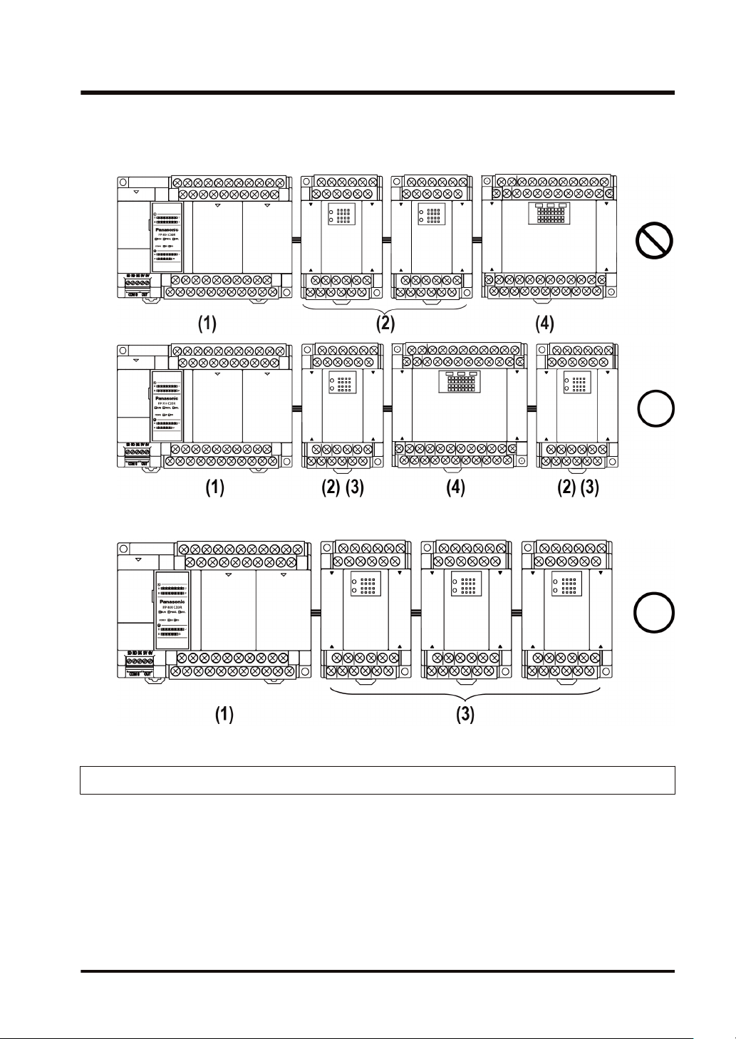
Restrictions on combinations of Expansion Units (2)
● The number of units which can be expanded depends on the Expansion Unit type.
Unit type Remarks
(1) FP-XH Control Unit
E14YR, E16R
(2) FP-X Expansion I/O Unit
(3) FP-X Expansion I/O Unit E16X, E16T, E16P (Ver. 3.0 or later)
(4) FP-X Expansion I/O Unit E30
E16X, E16T, E16P (earlier than Ver.
3.0)
Expansion I/O Unit that does not have a
built-in power supply
Expansion I/O Unit that does not have a
built-in power supply
Expansion I/O Unit that has a built-in
power supply
1-8 WUME-FPXHBASG-01
1.3 Restrictions on Combinations of Units
● Among the FP-X Expansion I/O Units, those in the group (2) in the above table cannot be
connected next to each other. However, they can be connected to the right of the Expansion
I/O Unit that has a built-in power supply.
● Among the FP-X Expansion I/O Units that do not have a built-in power supply, those in the
group (3) in the above table can be connected together up to three units.
1.3.2 Restrictions on Using FP-X Expansion FP0 Adapter
■
FP-X Expansion FP0 Adapter installation position
● Up to three FP0 Expansion Units can be connected via the FP-X Expansion FP0 Adapter.
● Up to seven FP-X Expansion Units can be connected when using the FP-X Expansion FP0
Adapter.
● Only one FP-X Expansion FP0 Adapter can be connected at the last position of the FP-X
Expansion Bus. Install it on the right of the FP-X Expansion Unit / FP-X0 Expansion Unit.
WUME-FPXHBASG-01 1-9
1.3 Restrictions on Combinations of Units
FP-XH
(1)
Control Unit
■
FP0 Expansion Unit / FP0 Intelligent Unit installation sequence
FP-X
(2)
Expansion Unit
FP-X
(3)
Expansion FP0
adapter
FP0 Expansion Unit
(4)
Intelligent Unit
● Install the FP0 Thermocouple Input Unit on the right side of all other FP0 Units. If it is
installed on the left side, the total precision will deteriorate.
● Install the FP0 CC-Link Unit on the right side of all other FP0 Units. There is no expansion
connector on the right side.
1.3.3 Restrictions on Combinations of Extension Cassettes
■
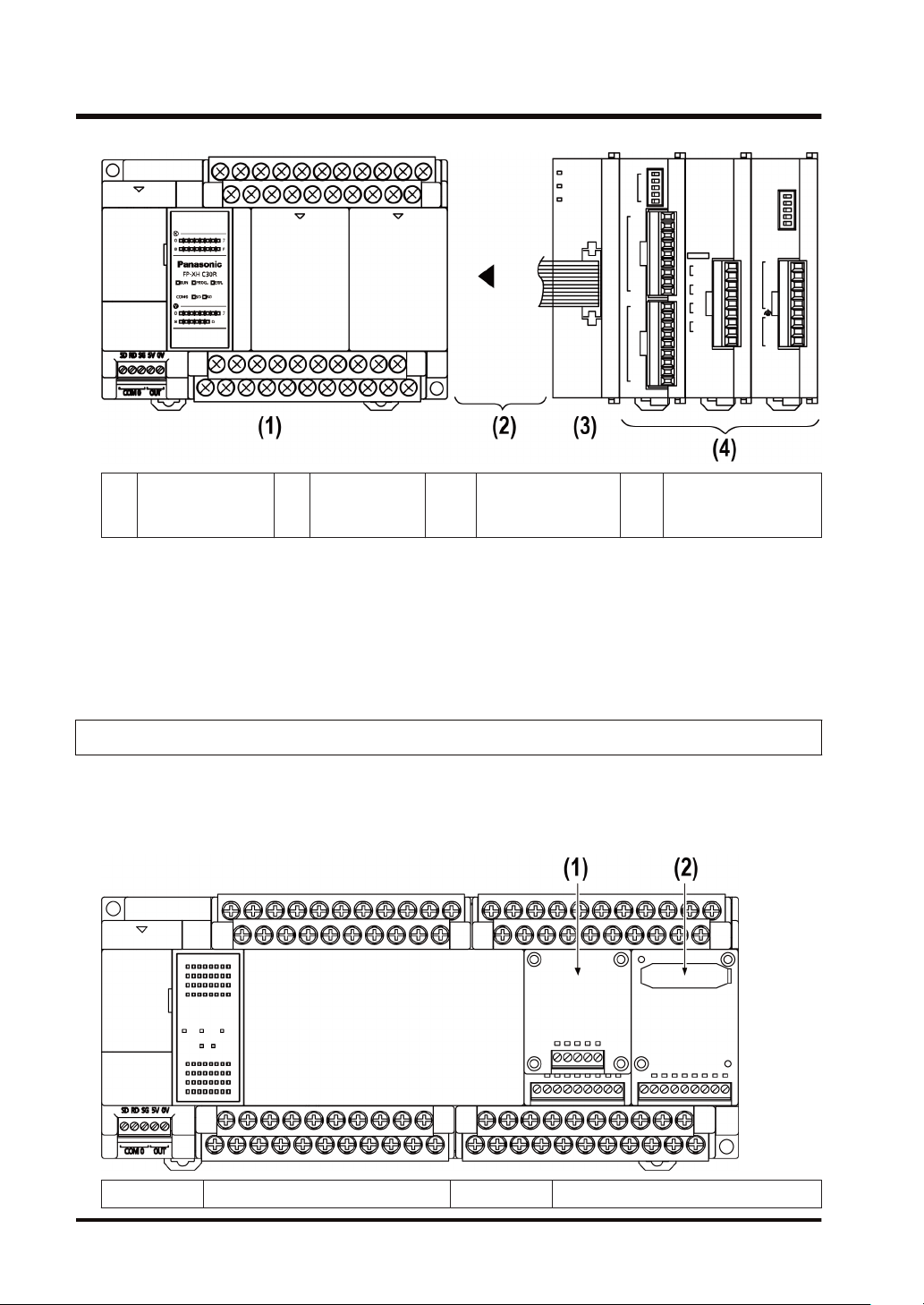
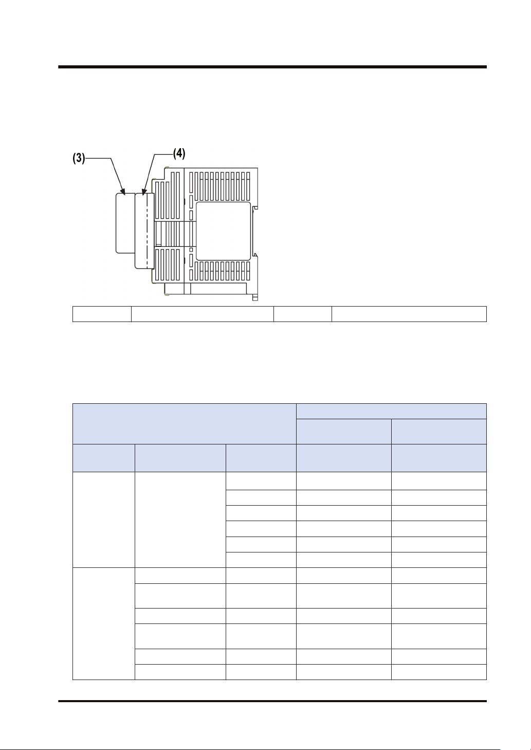
Extension Cassette mounting position (1)
● The FP-XH Control Unit is provided with two cassette mounting parts. In case of the C14
model, only the cassette mounting part 1 can be used.
(1) Cassette mounting part 1 (2) Cassette mounting part 2
1-10 WUME-FPXHBASG-01
1.3 Restrictions on Combinations of Units
■
Extension Cassette mounting position (2)
● The Function Cassette can be put together with the Communication Cassette and mounted
on the same cassette mounting part. When doing so, be sure to put the Communication
Cassette on top of the Function Cassette.
(3) Communication Cassette (4) Function Cassette
■
Number of of Extension Cassettes to be mounted
● Up to two Function Cassettes and up to two Communication Cassettes can be mounted.
■
Types of Extension Cassettes and mounting position (●: Available, ○:
Conditionally available, Blank: Not available)
Mounting parts on the Control Unit
Cassette type
Type Item name Product number
AFPX-COM1
AFPX-COM2 ● ●
Communicatio
n Cassette
(Note 1)
Function
Cassette
(Note 3)
Communication
Cassette
Analog Input Cassette AFPX-AD2 ● ●
Analog Output
Cassette
Analog I/O Cassette AFPX-A21 ● ●
Thermocouple
Cassette
RTD Cassette AFPX-RTD2 ● ●
Input Cassette AFPX-IN8 ● ●
AFPX-COM3 ● ●
AFPX-COM4 ● ●
AFPX-COM5 ● ●
AFPX-COM6 ● ●
AFPX-DA2 ● ●
AFPX-TC2 ● ●
Cassette mounting
part 1
FP-XH Control
Unit
(Note 2)
●
Cassette mounting
part 2
FP-XH Control Unit
(excluding C14)
(Note 2)
●
WUME-FPXHBASG-01 1-11

1.3 Restrictions on Combinations of Units
Mounting parts on the Control Unit
Cassette type
Type Item name Product number
Output Cassette AFPX-TR8 ● ●
Output Cassette AFPX-TR6P ● ●
I/O Cassette AFPX-IN4T3 ● ●
Pulse I/O Cassette AFPX-PLS
Master Memory
Cassette
(Note 1) When mounting it together with the Function Cassette, mount it on top of the Function Cassette.
AFPX-MRTC
(Note 2) With the AFPX-COM1, RS/CS control is possible.
(Note 3) When mounting the Function Cassette on C30, or C60 model, the Cassette can be mounted either on
the cassette mounting part 1 or cassette mounting part 2.
(Note 4) The Pulse I/O Cassette cannot be mounted on the Transistor Output Type Control Unit. If it is
mounted, the self-diagnostic error (27: Unit installed limit) will occur.
(Note 5) Only one FP-X Master Memory Cassette can be mounted. If two FP-X Master Memory Cassettes are
mounted, the self-diagnostic error (27: Unit installed limit) will occur.
Cassette mounting
part 1
FP-XH Control
Unit
(Note 4)
○
(Note 5)
○
Cassette mounting
part 2
FP-XH Control Unit
(excluding C14)
(Note 4)
○
(Note 5)
○
1.3.4 Restrictions on Communication Functions
● There are the following restrictions on functions to be used when using the communication
ports equipped with the Control Unit and Communication Cassettes.
● Allocated communication port numbers vary according to the mounting positions of
cassettes.
■
Types of communication ports / Communication Cassettes (●: Available, Blank:
Not available)
Allocated communication port no.
Product no.
Communication interface
Control
Unit
COM0 COM1 COM2 COM3 COM4
Control
Unit standard
equipment
AFPX-COM1
AFPX-COM2
RS-232C (3-wire type) x 1
channel
RS-232C (5-wire type) x 1
channel
RS-232C (3-wire type) x 2
channels
AFPX-COM3 RS-485 / RS-422 x 1 channel ● ●
RS-485 x 1 channel ● ●
AFPX-COM4
RS-232C (3-wire type) x 1
channel
Cassette mounting
●
part 1
part 2
● ●
● ● ● ●
● ●
Cassette mounting
1-12 WUME-FPXHBASG-01

1.3 Restrictions on Combinations of Units
Allocated communication port no.
Product no. Communication interface
Control
Unit
COM0 COM1 COM2 COM3 COM4
Ethernet port x 1 channel ● ●
AFPX-COM5
RS-232C (3-wire type) x 1
channel
AFPX-COM6 RS-485 x 2 channels ● ● ● ●
(Note 1) The RS-232C port of the AFPX-COM1 is a 5-wire type, and the RS/CS control can be performed.
(Note 2) For the AFPX-COM1, select either RS-485 or RS-422. Use the switch on the Communication Cassette
to select the port.
(Note 3) For the AFPX-COM4, both 1-channel RS-485 and 1-channel RS-232C (3-wire type) can be used.
(Note 4) For the AFPX-COM5, both 1-channel Ethernet and 1-channel RS-232C (3-wire type) can be used.
■
Available functions for each communication port (●: Available, ○: Conditionally
available, Blank: Not available)
Communication functions to be used
PLC Link ○ ○
MEWTOCOL-COM
MODBUS-RTU
Master ● ● ● ● ●
Slave ● ● ● ● ●
Master ● ● ● ●
Slave ● ● ● ●
General-purpose communication ● ● ● ●
(Note 1) For the PLC link, either one of the standard COM0 port mounted in the Control Unit and the COM 1
port of a Cassette can be used.
(Note 2) The COM4 port only supports MEWTOCOL-COM communication. In addition, the communication
parameters (unit number, communication format, baud rate) when the power is ON are same as the
setting of the COM3 port. After RUN, you can also change the conditions by SYS1 instruction.
Control
Unit
COM0 COM1 COM2 COM3 COM4
Cassette mounting
part 1
Cassette mounting
part 2
● ●
Allocated communication port no.
Cassette mounting
part 1
Cassette mounting
part 2
1.3.5 Restrictions on Combined Use of Functions
● For the FP-XH series, communication with external devices can be performed via up to a
maximum of five communication interfaces in combination of the standard COM0 port
mounted in the Control Unit and the COM1 to COM4 ports of the Communication Cassette.
● When using all five ports (COM0 to COM4), the usable baud rate is up to 115.2 kbps and
usable pulse output function is up to 2 axes. When using four or less ports, the usable baud
rate is up to 230.4 kbps and usable pulse output function is up to 6 axes.
WUME-FPXHBASG-01 1-13
1.4 Programming Tools
1.4 Programming Tools
1.4.1 Software Usage Environment and Applicable Cables
■
Tool software
Software type Operating system Hard disk capacity Product no.
Windows
Windows
Windows
Control FPWIN GR7
Windows
bit version)
Windows
Windows
Windows
Windows
Control FPWIN Pro7
Windows
Windows
bit version)
(Note 1) The latest version is provided free of charge via our website (https://industrial.panasonic.com/ac/e/
dl_center/software/). Use the latest version.
(R)
10 (32-bit version / 64-bit version)
(R)
8.1 (32-bit version / 64-bit version)
(R)
8 (32-bit version / 64-bit version)
(R)
7 SP1 or later (32-bit version / 64-
(R)
Vista SP2
(R)
XP SP3
(R)
10 (32-bit version / 64-bit version)
(R)
8.1 (32-bit version / 64-bit version)
(R)
8 (32-bit version / 64-bit version)
(R)
7 SP1 or later (32-bit version / 64-
120 MB or more AFPSGR7EN
400 MB or more AFPSPR7A
■
PC connection cable
● Use a commercial USB cable.
Cable type Length
USB 2.0 cable (A:Mini B) Max. 5 m
1.4.2 Applicable software version
For using the FP-XH, the following software versions are required.
1-14 WUME-FPXHBASG-01

Item Applicable version
Programming tool
software Control FPWIN
GR / GR7 / Pro7
Configurator PMX
C14/C30/C60
It is used for using the pulse output function in the table setting mode. It is
incorporated in the FPWIN GR / GR7 / Pro7 and can be started from the
option menu.
1.4 Programming Tools
FPWIN GR Ver. 2.93 or later
FPWIN GR7 Ver. 2.5 or later
FPWIN Pro7 Ver. 7.03 or later
WUME-FPXHBASG-01 1-15

(MEMO)
1-16 WUME-FPXHBASG-01

2 Control Unit Specifications
2.1 Names and Functions of Parts............................................................2-2
2.1.1 Names and Functions of Parts......................................................... 2-2
2.1.2 Specifications of Operation Indicator LEDs ..................................... 2-3
2.1.3 Specifications of COM0 Port............................................................ 2-4
2.2 Power Supply Specifications...............................................................2-5
2.2.1 AC Power Supply Type.................................................................... 2-5
2.2.2 AC Power Supply Type: Service Power Supply for Input Circuit ..... 2-5
2.2.3 DC Power Supply Type.................................................................... 2-6
2.3 Input and Output Specifications (Relay Output Type).........................2-7
2.3.1 Input Specifications.......................................................................... 2-7
2.3.2 Output Specifications ....................................................................... 2-8
2.4 Input and Output Specifications (Transistor Output Type) ..................2-9
2.4.1 Input Specifications.......................................................................... 2-9
2.4.2 Output Specifications ....................................................................... 2-10
2.5 Terminal Layout...................................................................................2-11
2.5.1 Relay Output (AC Power Supply Type)............................................ 2-11
2.5.2 Relay Output (DC Power Supply Type) ........................................... 2-12
2.5.3 Transistor Output (AC Power Supply Type) ..................................... 2-13
2.5.4 Transistor Output (DC Power Supply Type)..................................... 2-15
WUME-FPXHBASG-01
2-1
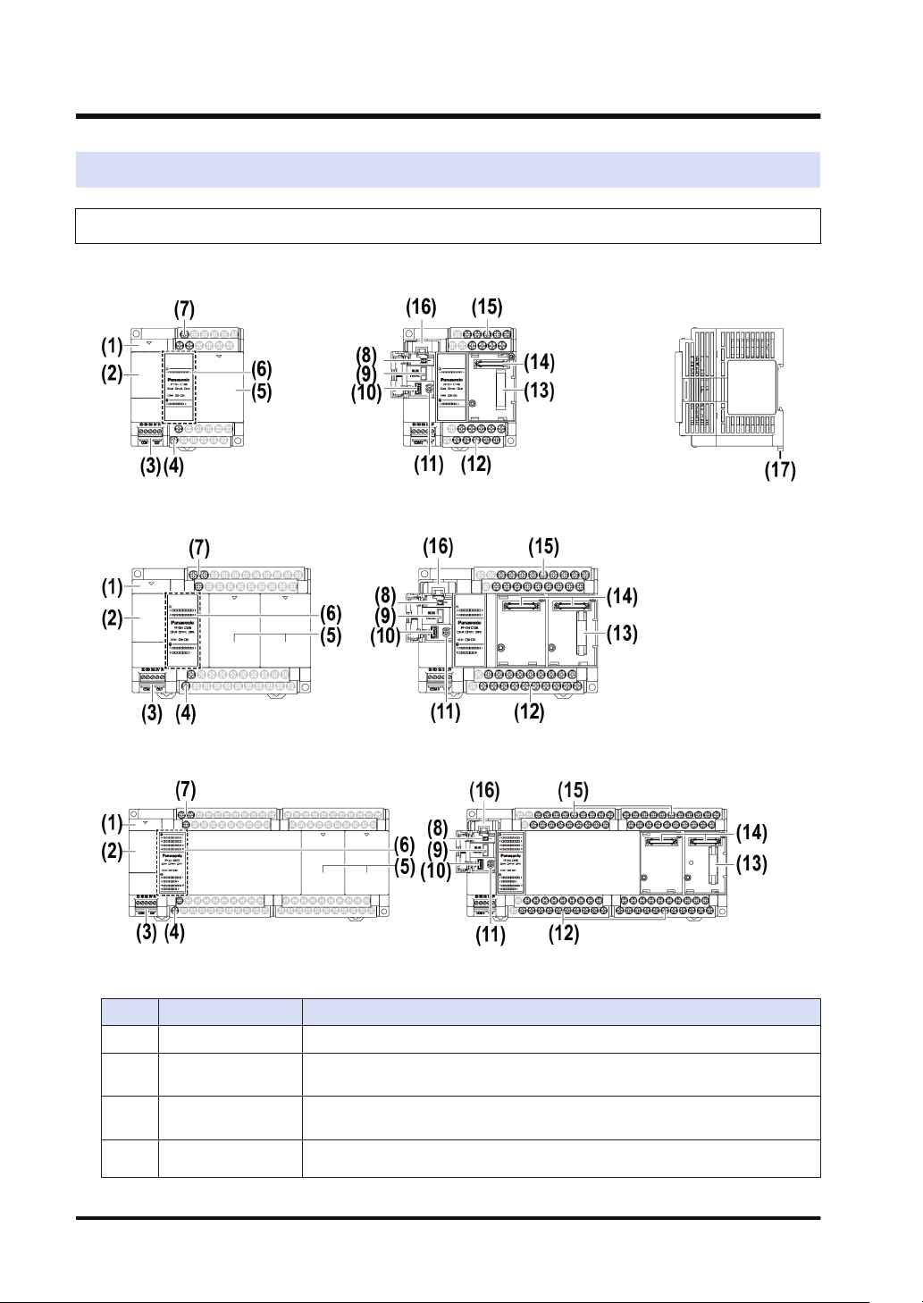
2.1 Names and Functions of Parts
2.1 Names and Functions of Parts
2.1.1 Names and Functions of Parts
■
FP-XH C14 Control Unit
■
FP-XH C30 Control Unit
■
FP-XH C60 Control Unit
■
Names and functions of parts
No. Name Function
(1) Battery cover This is a space for installing an optional backup battery.
(2) Operating unit cover
(3) COM0 port
Service power
(4)
supply
2-2 WUME-FPXHBASG-01
There are a built-in battery connector, RUN / PROG. mode selection switch,
USB port connector, and analog potentiometer.
Three-wire RS-232C port. A power supply terminal (5 V) is also provided for
connecting our Programmable Display GT Series.
It can be used as service power supply for the input circuit.
 Loading...