

Panasonic FP-X0 L14R, FP-X0 L40MR, FP-X0 L60R, FP-X0 L30R, FP-X0 L60MR User Manual
Phone: 800.894.0412 - Fax: 888.723.4773 - Web: www.clrwtr.com - Email: info@clrwtr.com

Safety Precautions
Observe the following notices to ensure personal safety or to prevent acci dents.
To ensure that you use this product correctly, read this User’s Manual thoroughly before use.
Make sure that you fully understand the product and information on safety.
This manual uses two safety flags to indicate different levels of danger.
WARNING
If critical situations that could lead to user’s death or serious injury is assumed by
mishandling of the product.
-Always take precautions to ensure the overall safety of your system, so that the whole
system remains safe in the event of failure of this product or other external factor.
-Do not use this product in areas with inflammable gas. It could lead to an explosion.
-Exposing this product to excessive heat or open flames could cause damage to the lithium
battery or other electronic parts.
-Battery may explode if mistreated. Do not recharge, disassemble or dispose of fire.
CAUTION
If critical situations that could lead to user’s injury or only property damage is
assumed by mishandling of the product.
-To prevent excessive exothermic he at or smoke generation, use this product at the values
less than the maximum of the characteristics and performance that are assured i n these
specifications.
-Do not dismantle or remodel the product. It could cause excessive exothermic heat or smoke
generation.
-Do not touch the terminal while turning on electricity. It could lead to an electric shock.
-Use the external devices to function the emergency stop and interlock circuit.
-Connect the wires or connectors securely.
The loose connection could cause excessive exothermic heat or smoke generation.
-Ground the protective earth (PE) terminal (Class D grounding). Failure to do so could lead to
an electric shock.
-Do not allow foreign matters such as liquid, flammable materials, metal s to go into the insid e
of the product. It could cause excessive exothermic heat or smoke generation.
-Do not undertake construction (such as connection and disconnection) while the power
supply is on. It could lead to an electric shock.
Copyright / Trademarks
-This manual and its contents are copyrighted.
-You may not copy this manual, in whole or part, without written con sent of
Panasonic Electric
Works SUNX Co., Ltd.
-Windows is a registered trademark of Microsoft Co rporation in the United States an d other
countries.
-All other company names and product names are trademarks or registered trademarks of
their respective owners.
PLC_BATPE
Phone: 800.894.0412 - Fax: 888.723.4773 - Web: www.clrwtr.com - Email: info@clrwtr.com

Table of Contents
Difference in Specifications Between FP-X0 Models
Before You Start
Programming Tool Restrictions
1. Unit Types and Restrictions ........................................................................ 1-1
1.1 Unit T
ypes ................................................................................................ 1-2
1.2 Restrictions on Unit Combinations ........................................................... 1-4
1.3 Programming Tools .................................................................................. 1-7
2. Specifications and Functions of Control Unit ............................................ 2-1
2.1 Pa rt
s and Functions ................................................................................. 2-2
2.2 Power Supply Specifications .................................................................... 2-4
2.3 Input/Output Specifications ...................................................................... 2-5
2.4 Analog Input Specifications (For L40 and L60 types) ............................... 2-8
2.5 Terminal Layout ..................................................................................... 2-12
3. Specifications of Expansion Units and Expansion FP0 Adapter .............. 3-1
3.1 FP-X Ex
pansion Units .............................................................................. 3-2
3.2 FP-X Expansion FP0 Adapter ................................................................ 3-10
4. I/O Alloc a t ion ................................................................................................ 4-1
4.1 I/O All
ocation ........................................................................................... 4-2
4.2 I/O Allocation of FP-X0 Control Unit ......................................................... 4-3
4.3 FP-X Expansion Unit I/O Allocation .......................................................... 4-3
4.4 Allocation of FP0/FP0R Expansion Unit ................................................... 4-4
5. Installation and Wiring................................................................................. 5-1
5.1 In st
allat i on ................................................................................................ 5-2
5.2 Expansion Method ................................................................................... 5-5
5.3 Power Supply ........................................................................................... 5-6
5.4 Wirin g o f Inp ut and Output ....................................................................... 5-8
5.5 Wirin g o f Ter m i nal Bl ock ........................................................................ 5-11
5.6 Setting and Wiring of COM Port (RS485) ............................................... 5-12
5.7 Handling of Backup Battery (For L40 and L60 types) ............................. 5-13
5.8 Safety Measures .................................................................................... 5-16
6. Communication Functions .......................................................................... 6-1
6.1 Funct
ions and Types ................................................................................ 6-2
6.2 Communicaton Port Type ........................................................................ 6-4
6.3 Communication Specifications ................................................................. 6-5
6.4 Computer Link.......................................................................................... 6-7
6.5 General-purpose Serial Communication................................................. 6-17
6.6 PC(PLC) link Function (For L40MR and L60MR types) .......................... 6-31
6.7 MODBUS RTU Communication (For L40MR and L60MR types) ............ 6-46
Phone: 800.894.0412 - Fax: 888.723.4773 - Web: www.clrwtr.com - Email: info@clrwtr.com

7. High-speed Counter, Pulse Output and PWM Output Functions .............. 7-1
7.1 Overview of Each Functions ..................................................................... 7-2
7.2 Function Specifications and Restricted Items ........................................... 7-4
7.3 High-speed Counter Function ................................................................... 7-6
7.4 Pulse Output Function ............................................................................ 7-14
7.5 PWM Output Function ............................................................................ 7-35
8. Security Functions ....................................................................................... 8-1
8.1 Pa sswor d Protect Func tion ....................................................................... 8-2
8.2 Upload Protection ..................................................................................... 8-8
8.3 Setting Function for FP Memory Loader ................................................... 8-9
8.4 Table of Security Settings/Cancel ........................................................... 8-12
9. Other Functions ............................................................................................ 9-1
9.1 Clock/Calendar Function (For L40 and L60 types) .................................... 9-2
9.2 Sampling Trance Function (For L40 and L60 types) ................................. 9-4
9.3 Time Constant Processing ........................................................................ 9-7
9.4 P13 (PICWT) Instruction ........................................................................... 9-8
10. Self-Diagnostic and Troubleshooting ....................................................... 10-1
10.1 Sel f-Diagnostic function ........................................................................ 10-2
10.2 Troubleshooting .................................................................................... 10-3
10.3 Oper ati on Errors ................................................................................... 10-7
11. Precautions During Programming ............................................................ 11-1
11.1 Use of Duplicated Output (Double Coil) ................................................ 11-2
11.2 Instr u c ti o ns of Leading Ed ge Detection M ethod .................................... 11-4
11.3 Precautions for Pr ogramming ............................................................... 11-7
11.4 Rewrite Function During RUN ............................................................... 11-8
11.5 Processing During Forced Input and Output ....................................... 11-13
12. Specifications ............................................................................................. 12-1
12.1 Table of Specifications..........................................................................
12-2
12.2 Relays, Memory Areas and Constants .................................................. 12-9
13. Dimensions and Cable Specifications ...................................................... 13-1
13.1 Dimensions ........................................................................................... 13-2
13.2 Cable/Adapt er S p ecificati o ns ................................................................ 13-3
14. Appendix ..................................................................................................... 14-1
14.1 System Registers / Special Internal Relays / Special Data Registers .... 14-2
14.2 Table of Basic Instructions .................................................................. 14-35
14.3 Table of High-level Instructions ........................................................... 14-43
14.4 Table of Error codes ........................................................................... 14-63
14.5 MEWTOCOL-COM Communication Commands ................................ 14-76
14.6 Hexadecimal/Binary/BCD ................................................................... 14-77
14.7 ASCI I Codes ....................................................................................... 14-78
Phone: 800.894.0412 - Fax: 888.723.4773 - Web: www.clrwtr.com - Email: info@clrwtr.com

Difference in Specifications Between FP-X0 Models
The following tables show the main differences between each FP-X0 models. Ch eck those d ifferences
thoroughly before use.
Comparison of hardware specifications
Item
L14
L30
L40
L60
Service po wer supply for
input
None 24V DC 0. 3 A 24V DC 0. 3 A 24V DC 0.3 A
No. of
controllable
I/O points
Control
unit
14 points
DC input: 8
Relay o utput: 4
Tr. output: 2
30 points
DC input: 16
Relay o utput: 10
Tr. output: 4
40 points
DC input: 24
Relay o utput: 12
Tr. output: 4
60 points
DC input: 32
Relay o utput: 24
Tr. output: 4
Expansion
unit
Cannot be connected.
Max. 3 units
(Max. 90 points for expansion units)
Analog input None
Analog input x 2 points
One of the followings can be input
to the terminal block of the control
unit or they can be connected in
combination.
(1) C onn ect potenti omet er.
(2) Connect thermister.
(3) Input voltage 0 to 10V.
Clock/calendar function
(Realt im e cloc k)
None Built in
Backup battery Cannot be installed.
Can be installed.
(1) Operation memory c an be s et
whether to be held or not by system
registers.
(2) Clock/calendar (realtime clock)
function can be used.
Backup of operaiton
memory to F-ROM when
power is cut off
Counter: 6 points,
Internal relay: 80 points,
Data register: 300 words
Counter: 16 points,
Internal relay: 128 points,
Data register: 302 words
Comparison of communication interfaces
Item
L14 / L30 / L40 / L60
L40M / L60M
Tool
port
Interface
RS232C
RS232C
Usable function
- MEWTOCOL-slave
(L14/L30: 118 bytes/f rame)
- (L40/L60: 2k bytes/frame)
- General-p urpose serial
communication
-
Modem Initialization
- MEWTOCOL-slave
(2k bytes/frame)
- General-p urpose serial
communication
- Modem Initialization
COM
port
Interface
None
RS485
Usable function None
- MEWTOCOL-(master/slave)
(2k bytes/frame)
- General-p urpose commun ica t ion
- MODBUS RTU (master/sl a v e)
- PLC link
-
Modem initialization
Phone: 800.894.0412 - Fax: 888.723.4773 - Web: www.clrwtr.com - Email: info@clrwtr.com

Comparison of high-speed counter and pulse output specifications
Item
L14 / L30
L40 / L60
High-speed counter
Single-phase 4 chs or
2-phase 2 c hs
Single-phase: Max. 20 kHz
2-phase: Max. 20 kHz
Single-phase 4 chs or
2-phase 2 c hs
Single-phase: Max. 50 kHz
2-phase: Max. 20 kHz
Pulse o utput / PW M output
Max. 1 ch
Pulse o utput:
Max. 20 kHz
PWM output:
Max. 1.6 kHz
Max. 2 chs
Pulse o utput:
Max. 20 kHz
PWM output:
Max. 1.6 kHz
Max. 2 chs
Pulse output: Max. 50 kHz
PWM output: M ax. 3 kHz
Related
instructions
Trapezoidal
control
F171 (SPDH)
(Acceleration ti me an d
deceleration time can be set
individually. Target speed cannot
be changed after the execution.)
Same as o n the l eft.
JOG
operation
F172 (PLSH)
(Acceleration ti me an d
deceleration time can be set
individually. Target speed cannot
be changed after the execution.)
Same as o n the l eft.
Home return
F177 (HOME)
(Deviation counter signal cannot
be used for L14 type.)
F177 (HOME)
Linear
interpolation
Not available F175 (SPSH)
PWM output
F173 (PWMH)
Same as o n the l eft.
In put pulse
measurement
Not available F178 (PLSM)
Note1) Typical specifications are described here. For t he detail s of t he restrict ions on combinations, refer
to Chapter 7.
Comparison of software specifications
Item
L14 / L30
L40 / L60、L40M / L60M
Program capacity
2.5k stpes
8k steps
Ari thmetic processing sp eed
From 0. 08µs/step
(by basic instruction)
From 0. 32µs (MV instruction)
(by high-level instruction)
Up to 3000 steps:
From 0. 08µs/step
(by basic instruction)
From 0. 32µs (MV instruction)
(by high-level instructio n)
From 3001 steps:
From 0. 58µs/step
(by basic instruction)
From 1. 62µs (MV instruction)
(by high-level instructio n)
Operation
memory
In ternal relay
1008 points
4096 points
Timer a nd co unter
256 points
1024 points
Li nk relay
None
2048 points
Note1)
Data register
32765 words
32765 words
Link register
None
256 words
Note1)
MCR points
32 points
256 points
No. of l abels (JP and LOOP)
100 points
256 points
No. of step ladders
128 stages
1000 stages
No. of subroutines
100 subroutines
500 subroutines
Simultaneous rewriting
capacity during RUN
Max. 128 steps Max. 512 steps
Sampling trace
None
Available
Note1) The PLC link function is available for L40M and L60M types.
Phone: 800.894.0412 - Fax: 888.723.4773 - Web: www.clrwtr.com - Email: info@clrwtr.com

Before You Start
Operating environment (Use the unit within the range of the general specifications when installing)
*Ambient t emperatures:0 ~ +55 ℃
*Ambient humi di ty: 10% to 95% RH (at 25°C, non-condensing)
*Keep the height below 2000m.
*For use in pollution Degree 2 environment.
*Do not use it in th e follow ing environments.
-Direct sunlight
-Sudden temperature changes causing condensation.
-Inflammable or corrosive gas.
-E-xcessive airborne dus t , met al part icles o r saline matter.
-Benzine, paint thinner, alcohol or other organic solvents or strong alkaline solutions such as
ammo nia or caustic so da.
-Direct vibration , shock or direct drop of water.
- Influence from pow er tr ansmiss ion lines, high volt age eq uipment, p ower cabl es, power equipment,
radio t ransmi t ter s, or any other equipm ent that w ould gene rate high switching surges .
(Min.100mm or less)
Static electricity
-Bef ore touching the unit, always touch a grounded piece of meta l in or der t o dis charge static el ectr icity.
-In d r y lo cati ons, exces si ve stati c electrici ty can cau se problems.
Wiring the Power Supply to the Control Unit
-Use a pow er s upply wire th at is thicker than 2 mm2 ( AWG14), and twist it.
-The unit has sufficient noise immunity against the noise generated on the power line.
How ever, it is recommen ded to take measures for reducing no is e such as using a i solating trans former
before supplying the power.
-Allocate an independent wiring for each power supplying line, input/output device and operating device.
-If usi ng a power supply witho ut a pr otective circuit, power should be s upplied throug h a protect ive
elemen t suc h as a fuse.
-Be sure to supply power to a control and an expansion units from a single power supply.
Turning on/off of the power of all the units must be conducted simultaneously.
Power supply sequence
In order to protect the power supply sequence, make sure to turn off the control unit before the
input/output power supply. If the input/output power supply is turned off before the control unit, or if the
control unit is not shut off momentarily, the controller detects change of input level, and might conduct an
unexpected operation.
Before turning on the power
When turning on the power for the first time, be sure to take the precautions given below.
- When per forming ins tal lation, ch eck t o m ake s ure t hat t here are no scraps of wir i ng, part icularly
conductive fragments, adhering to the unit.
- Verify that the power supply wiring, I/O wiring, and power supply voltage are all correct.
- Sufficiently tighten the installation screws and te rminal screws.
- Set the mode selector to PROG. Mode.
Phone: 800.894.0412 - Fax: 888.723.4773 - Web: www.clrwtr.com - Email: info@clrwtr.com

Before entering a program
Be su re t o perform a program clear operation before entering a program.
Operation procedure when using FPWIN GR Ver.2
Select “Onl in e E dit Mode” on the FPWIN GR “On line” menu.
Select “Clear Program” on the “Edit” menu.
When the confirmation dialog box is displayed, click on “Yes” to clear the program.
Request concerning program storage
To prevent the accidental loss of programs, the user should consider the following measures.
- Drafting of documents
To a voi d acciden tally l osi ng programs, destroying f iles, or overwriting the contents of a file, documents
should be printed out and then saved.
- Specifying the password carefully
The password setting is designed to avoid programs being accidentally overwritten. If the password is
fo rgotten, howev er, it will be impo ssible to overw r it e t he program even if you want t o. Al so, if a
possword is forcibly bypassed, the program is deleted. When specifying the password, note it in the
specifications manual or in another safe location in case it is forgotten at some point.
- Upload protection
When the upload protectio n sett ing i s spec ified, prog r ams will be di salbed to be r ead o ut . If the setting
is c ancell ed forci bly, all programs and system r egister s wil l be delet ed. Therefore, note that pr ograms
and system registers should be managed on your o wn responsi bi lity.
Backup battery
Do not install the battery when it is not used.
There is a possibility of leak if the battery remains discharged.
Phone: 800.894.0412 - Fax: 888.723.4773 - Web: www.clrwtr.com - Email: info@clrwtr.com

vii
Programming Tool Restrictions
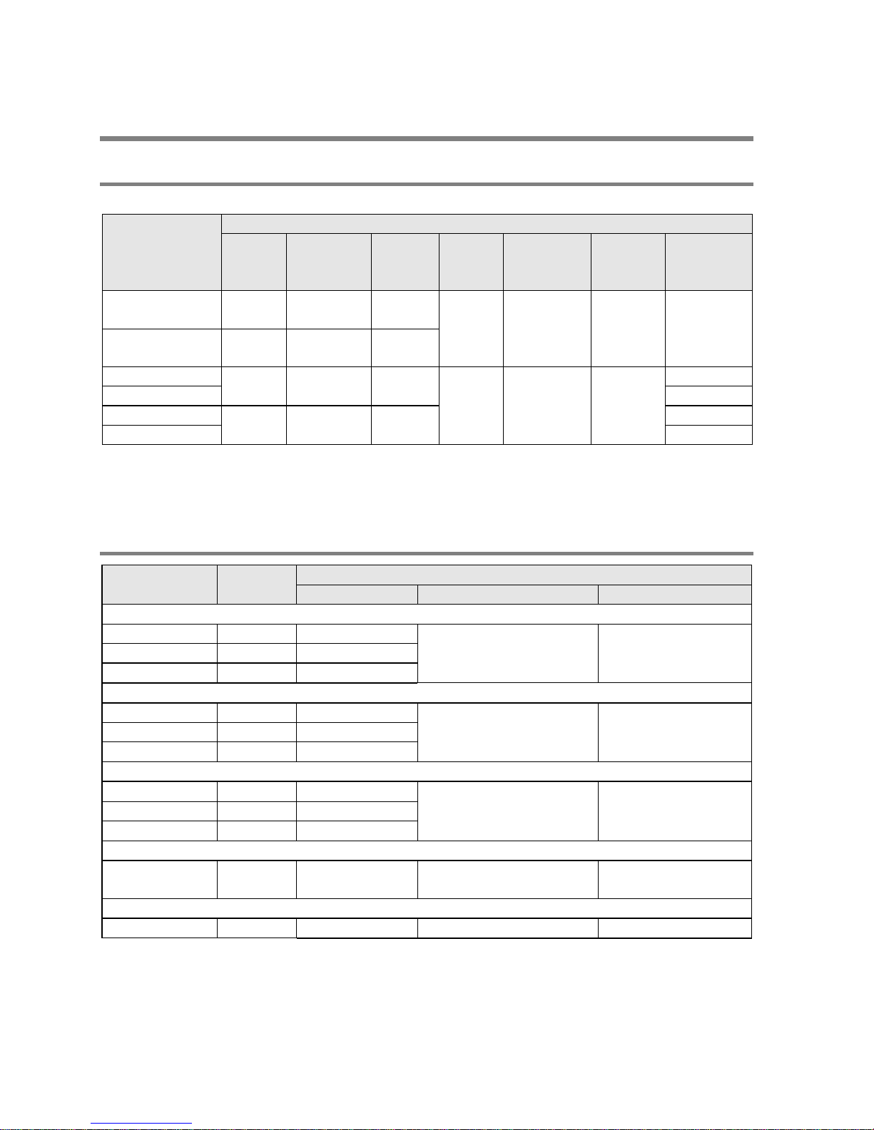
Restrictions on usable programming tools depending on the units
Type of programming tool
Type of unit
AFPX0
Windows software
FPWIN GR Ver.2
Used
(Ver. 2.91 or later)
FPWIN GR Ver.1 Not used
Windows software
Conforms to IEC61131-3
FPWIN Pro Ver.6
Used
(Ver. 6.3 or later)
Handy programming unit
AFP1113V2
AFP1114V2
Not used
AFP1113
AFP1114
Not used
AFP1111A
AFP1112A
AFP1111
AFP1112
Not used
FP memory loader
AFP8670
AFP8671
Used
(Ver.2.0 or later)
Note: Precautions concerning version upgrade
- In case of using FPWIN GR Ver.1, please purchase upgrade model FPWIN GR Ver.2.
- FPWIN GR Ver.2 can be upgraded free of charge at our web site.
- FPWIN Pro Ver.6 can be upgraded free of charge at our web site.
- The handy programming unit cannot be used.
Do not download any programs for other units such as FP1 to the FP-X0 using the handy programming
unit.
Phone: 800.894.0412 - Fax: 888.723.4773 - Web: www.clrwtr.com - Email: info@clrwtr.com

Phone: 800.894.0412 - Fax: 888.723.4773 - Web: www.clrwtr.com - Email: info@clrwtr.com

Chapter 1
Unit Types and Restrictions
Phone: 800.894.0412 - Fax: 888.723.4773 - Web: www.clrwtr.com - Email: info@clrwtr.com
1.1 Unit Types
1.1.1 FP-X0 Control Units
A: Available N/A: Not available
Product No.
Specifications
DC
input
Transistor
(NPN)
output
Relay
output
Analog
input
Expansion
Clock/
calender
COM port
(RS485
port)
AFPX0L14R
8
points
2 points 4 points
N/A N/A N/A N/A
AFPX0L30R
16
points
4 points
10
points
AFPX0L40R
24
points
4 points
12
points
2
points
A A
N/A
AFPX0L40MR A
AFPX0L60R
32
points
4 points
24
points
N/A
AFPX0L60MR A
Note1) For all the units, the power supply is 100 to 240 V AC, and DC input is 24 V DC (Common
polar i t ies + & - common).
Note2) An optional backup batt ery is required to use the clock/calender functi on.
1.1.2 FP-X E xpan si on Un it (Can be ad de d to L40/ L60 on ly)
Product No.
No. of I/O
points
Specifications
Power supply
Input
Output
Relay type ( Ry typ e)
AFPX-E16R 8/8 -
24 V DC (Common
polar i t ies + & - common)
Relay
AFPX-E30R
16/14
100 to 240 V AC
AFPX-E30RD
16/14
24 V DC
Transi s tor type (NPN ) (T r type)
AFPX-E16T
8/8
-
24 V DC (Common
polar i t ies + & - common)
Transistor
(NPN)
AFPX-E30T 16/14 100 to 240 V AC
AFPX-E30TD 16/14 24 V DC
Transi s tor type (PNP ) (T r type)
AFPX-E16P
8/8
-
24 V DC (Common
polar i t ies + & - common)
Transistor
(PNP)
AFPX-E30P 16/14 100 to 240 V AC
AFPX-E30PD
16/14
24 V DC
Input-only typ e
AFPX-E16X 16/0 -
24 V DC (Common
polar i t ies + & - common)
-
Output-only type (R elay type )
AFPX-E14YR
0/14
- - -
Note) A n 8-cm expansion cable is provided with an expansion unit
Phone: 800.894.0412 - Fax: 888.723.4773 - Web: www.clrwtr.com - Email: info@clrwtr.com
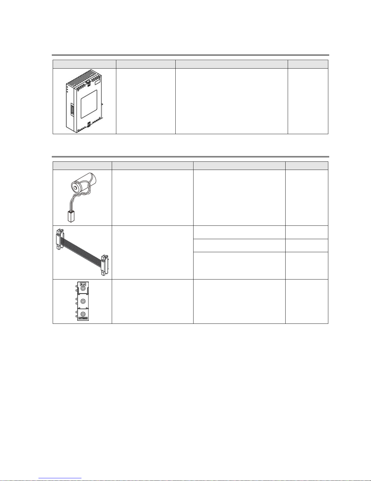
1.1.3 FP-X E xpan si on FP0 A dapt er (Can be added to L40/ L6 0 onl y)
Appearance
Name
Specifications
Product No.
FP-X Expansion
FP0 adapter (with 8
cm expansion
cable, power supply
cable)
For connecting FP0 expansion unit to
control unit
AFPX-EFP0
1.1.4 Related Parts
Appearance
Name
Description
Product No.
Backup battery
Necessary for the backup of
operation memory, real-time
cl ock data.
AFP8801
FP-X expansion cable
Note)
8 cm AFPX-EC08
30 cm AFPX-EC30
80 cm AFPX-EC80
FP0 mounting plate
(slim type)
Used for expansion FP0
adapter and FP0 Expansion
unit, 10 pcs/pack
AFP0803
Note) T he total length of the exapansion cable should be within 160 cm.
Phone: 800.894.0412 - Fax: 888.723.4773 - Web: www.clrwtr.com - Email: info@clrwtr.com
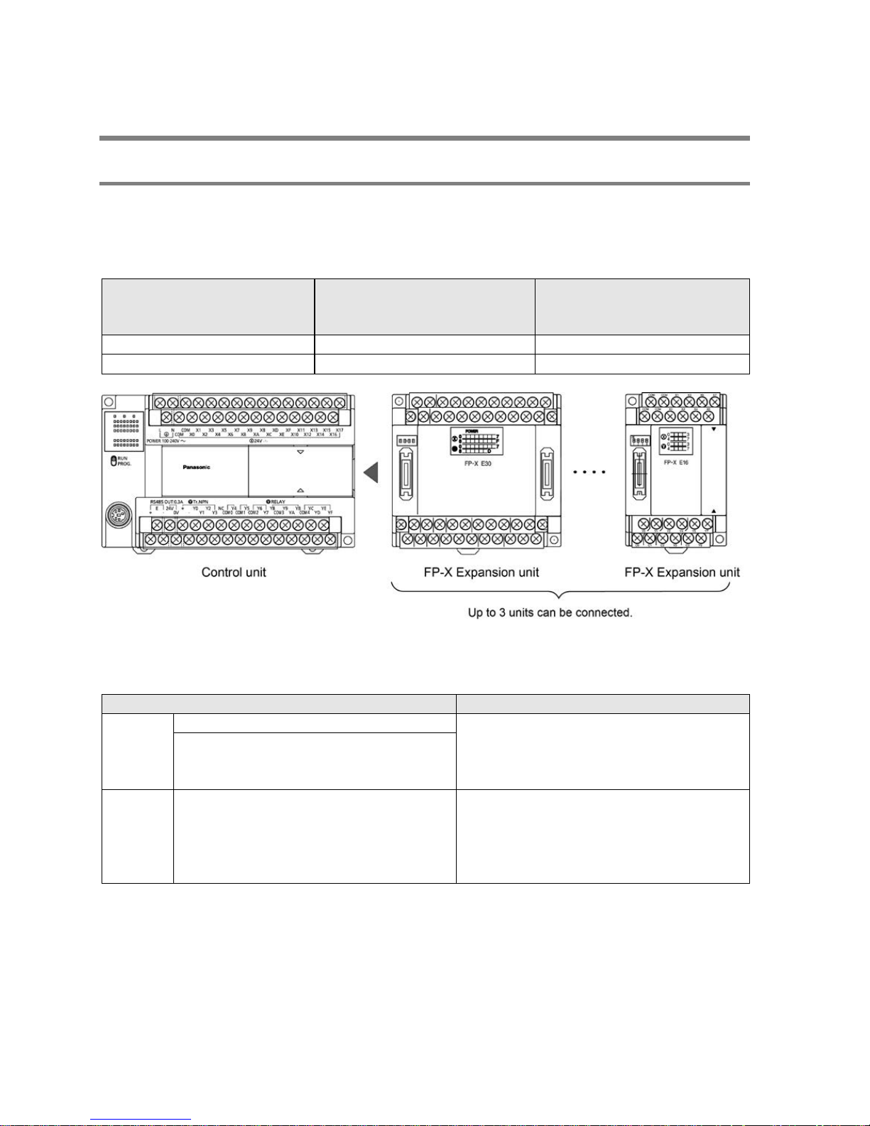
1.2 Restrictions on Uni t Combina t ions
1.2.1 Restric tions on FP-X Expansion Unit (For L40/ L60 only )
Restrictions on type of FP-X0 control unit s
- Up to three FP -X expansion units can be connected to FP-X0 L40 or L60 control unit.
- The maximum number of points when installing expansion units is as below.
Controllable I/O points
Type of control unit
Numbe r of I/O points when
using control unit
Number of I/O points when
using 3 units of E30
expansion I/O unit
FP-X0 L40R Control unit 40 points Max. 130 points
FP-X0 L60R Control unit
60 points
Max. 150 points
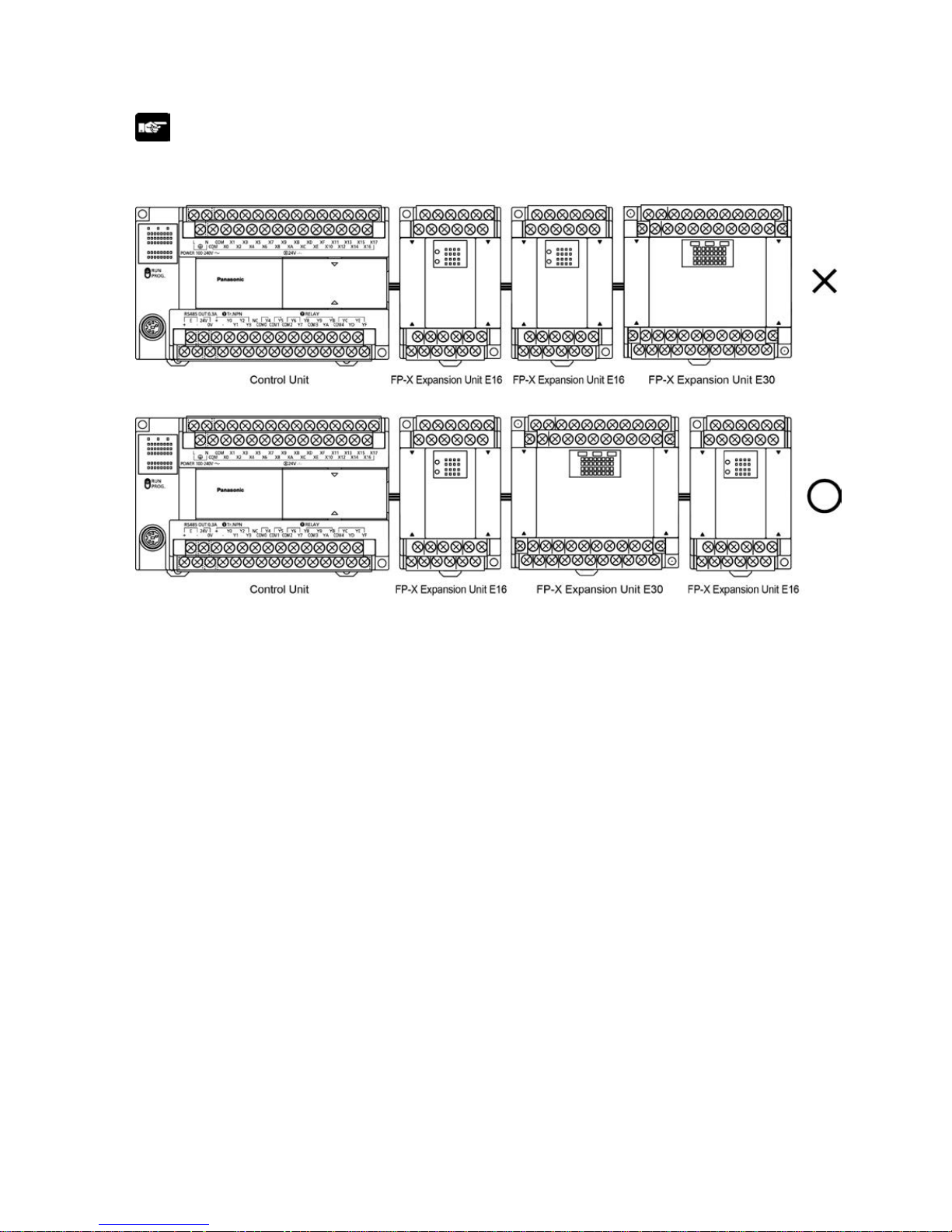
Restrictions on type of FP-X expansion units
- Up to three FP -X expansion units can be connected to FP-X0 L40 or L60 control unit, however, the
installable positions and the number of units differ depending on the type of expansion units as below.
Type of expansion unit
Installable position
Group A
FP-X E30 Expansion Unit
Can be installed at any position within the
limits described in t he abo ve fi gure.
FP-X E16 Expansion Unit (Ver.3)
FP-X E16T Expansion Unit (Ver.3)
FP-X E16P Expansion Unit (Ver.3)
Group B
FP-X E14YR Expansion Unit
FP-X E16R Expansion Unit
FP-X E16X Expansion Unit (Ver.2 or older)
FP-X E16T Expansion Unit (Ver .2 or older)
FP-X E16P Expansion Uni t(Ver.2 or ol der)
The expnasion units of group B do not have
a built-in ci rcuit t o supp l y bus power to t he
expansion unit installed on the right . FP-X
E16/E14 expansion units cannot be installed
on the right-hand side of those units.
- Up t o eight units of FP-X can be connected, however, the restrictions on each expansion unit vary.
- For AFPX-E16/E14: Two units cannot be connected consecutively since the power should be supplied
from the unit with the power supply (as no power supply is built in AFPX-E16).
E16 expansion I/O unit cannot be connected on the right side of the control unit or AFPX-E30.
- For AFPX-E30: There is no rest ri ction on AFPX-E30 so that up to 8 units can be connected
consecutively.
- The total length of t he expansion cable should be within 160 cm.
Phone: 800.894.0412 - Fax: 888.723.4773 - Web: www.clrwtr.com - Email: info@clrwtr.com
Note: Restrictions on installing AFPX-E16/E14:
Target models: FP-X E14YR expansion unit, FP-X E16R expansion unit, Fp-X 16X expansion unit (Ver.2
or older), FP-X E16T expansion unit (Ver.2 or older), FP-X E16P expansion unit (Ver.2 or older)
Restriction on the length of FP-X expansion cable
- When using an expansion cable AFPX-EC30 (30 cm type) or AFPX-EC80 (80 cm type) sold separately,
the total length of the expansion cables should be within 160 cm.
Phone: 800.894.0412 - Fax: 888.723.4773 - Web: www.clrwtr.com - Email: info@clrwtr.com
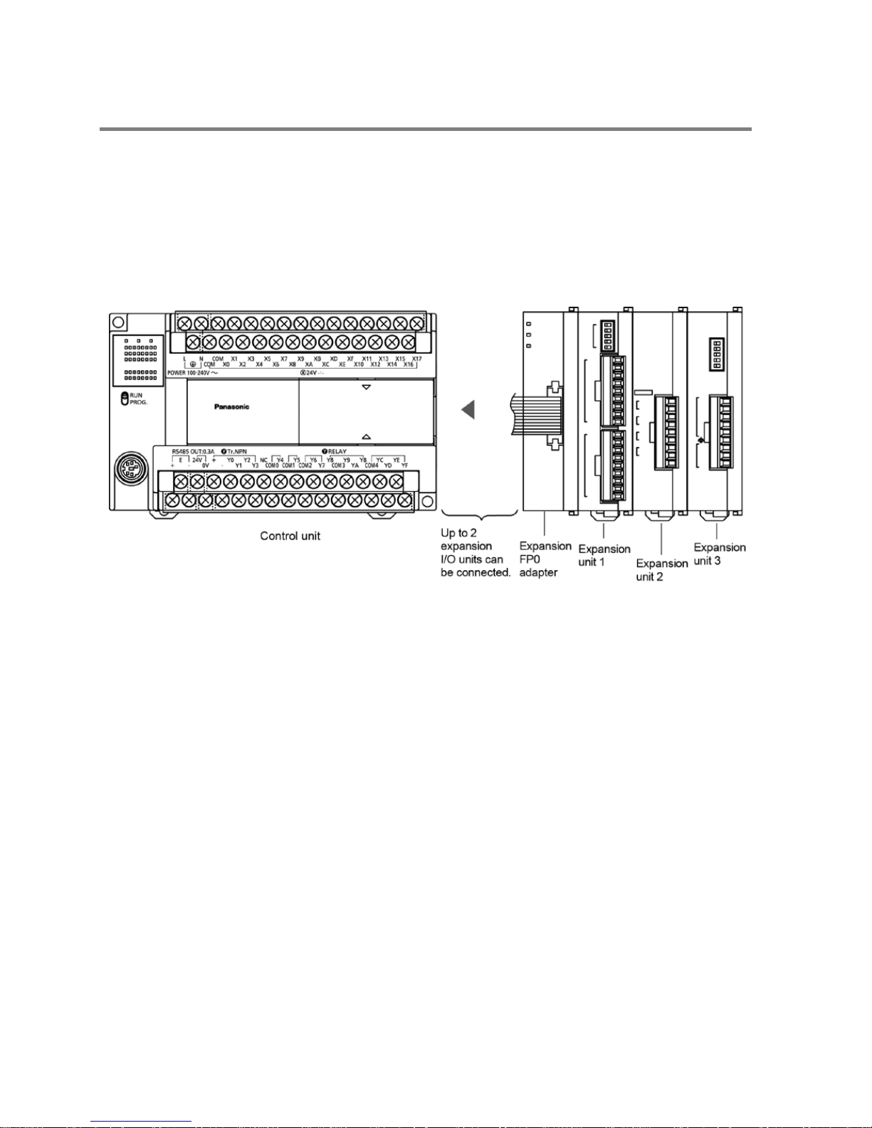
1.2.2 Restrictions on Usin g Ex pans ion FP0 A da pter (F or L40 /L6 0 onl y)
Restrictions on type of FP-X0 cont rol unit s
- Only one expansion FP0 adapter can be connected to FP-X0 L40 or L60 control unit .
Restrictions on installation positions of Expansion FP0 adapter
- When connecting the expansion FP0 adapter to FP-X0 L40 or L60 control unit, only one unit can be
connected at the last position of the expansion bus. Cnnect it on the righ-hand side of all other FP-X
expansion units.
- Up to two FP-X expansion I/O units can be installed between the control unit and expansion FP0
adapter.
Restrictions on installation positions of FP0/FP0R units
- Up to three FP0/FP0R expansion units and advanced units can be installed on the right-hand side of
the expansion FP0 adapter.
- Note) Install the FP0 thermocouple unit on the right side of all other expansion units. If it is installed on
th e lef t side, th e tot al pr ecis ion will deteriorate.
- Install t he FP0 CC-Link slave uni t on t he ri ght side of th e other expans ion units. There is no expansion
connector on the right side.
Phone: 800.894.0412 - Fax: 888.723.4773 - Web: www.clrwtr.com - Email: info@clrwtr.com

1-7
1.3 Programming Tools
1.3.1 Software Environment and Suitable Cable
Standard ladder diagram tool software FPWIN-GR Ver.2
Type of software OS (Operating system)
Hard disk
capacity
Product No.
FPWIN GR Ver.2
Englishlanguage menu
Full type
Windows98
WindowsMe
Windows2000
WindowsXP
Windows Vista
Windows7
40MB or
more
AFPS10520
Upgrade
version
AFPS10520R
Note1) Ver.1.1 must be installed to install the upgrade version.
Note2) Ver.2.0 can be upgraded to the latest version after Ver. 2.1 free of charge at our web site
Conforms to IEC61131-3 programming tool software FPWIN-Pro Ver.6
Type of software OS (Operating system)
Hard disk
capacity
Product No.
FPWIN Pro Ver.6
English-language menu
Windows2000
WindowsXP
Windows Vista
100MB or more FPWINProFEN6
Note1) The small type and upgrade version is not available for Ver.6.
Note2) Ver.6.0 can be upgraded to the latest version after Ver. 6.1 free of charge at our web site
Type of computer and suitable cable
For the connection between a personal computer (RS232C) and the control unit (RS232C)
D-sub connector cable
PC side connector PLC side connector Specifications Product No.
D-sub 9-pin
female-Mini DIN round 5-pin L type (3 m) AFC8503
female-Mini DIN round 5-pin Straight type (3 m) AFC8503S
Note) A USB/RS232C conversion cable is necessary to connect with a personal computer without a
serial port using a PC connection cable.
Phone: 800.894.0412 - Fax: 888.723.4773 - Web: www.clrwtr.com - Email: info@clrwtr.com

Phone: 800.894.0412 - Fax: 888.723.4773 - Web: www.clrwtr.com - Email: info@clrwtr.com

Chapter 2
Specifica tions and Functions of Control
Unit
Phone: 800.894.0412 - Fax: 888.723.4773 - Web: www.clrwtr.com - Email: info@clrwtr.com
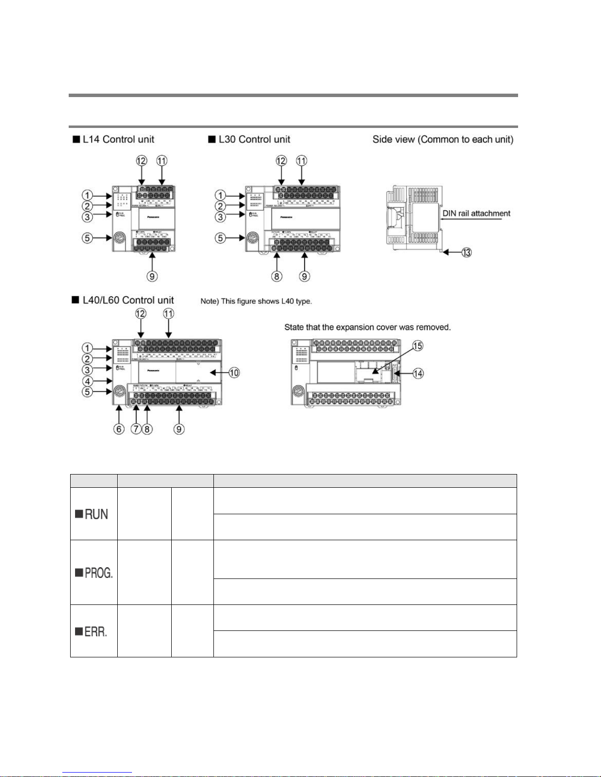
2.1 Parts and Functions
2.1.1 Parts and Functions
○
1
Status indicator LEDs
These LED s display t he current mode of operation or the occurrence of an error.
LED
LED and operation status
RUN Green
Lights when in the RUN mode and indicates that the program is
being executed.
It flashes during forced input/output. (The RUN and PROG. LEDs
flash alternately.)
PROG. Green
Lights when in the PROG. Mode and indicates that operation has
stopped.
Lights when in the PROG. Mode duri ng forced input/output.
It flashes during forced input/output. (The RUN and PROG. LEDs
flash alternately.)
ERROR/
ALARM
Red
Flashes when an error is detected during the self-diagnostic
function. (ERROR)
Lights if a hardware error occurs, or if oepration slows because of
the program, and the watchdog timer is activated . (AL ARM)
○
2
Input/output indicator LEDs
Indicates the on/off status of the input and output.
Phone: 800.894.0412 - Fax: 888.723.4773 - Web: www.clrwtr.com - Email: info@clrwtr.com

○
3
Switch position
RUN/PROG. mode switch
This switch is used to change the operation mode of the PLC.
Operation mode
RUN (upward)
This sets the RUN mode. The program is executed is executed and operation
begins.
PROG. (downwor d)
This sets the PROG. mode. The operation stops.
• The remote switching operation from the programming tool is operable.
• When performing remote switching from the programming tool, the setting of the mode switch and the
actual mode of operation may differ. Verify the mode with the status indicator LED.
• Restart FP Σ to operate in the mode set with the RUN/PROG. mode switch.
○
4
COM port baud rate switch
This switch is used to change the baud rate of the COM port between 115200 bps and 19200 bps.
Position of switch: On the left side; 115200 bps, On the right side; 19200 bps
○
5 Tool port (RS232C)
This connector is used to connec t a pr ogr amming tool.
A commercial mini-DIN 5-pin c onn ector is used f or th e tool port on the contro l unit.
Pin No.
Signal name
Abbreviation
Signal direction
1
Signal Ground
SG −
2
Send Data
SD
Unit → E x ternal devi ce
3
Rec eive Data
RD
Unit ← Ext ernal devic e
4
(Not used) − −
5
+5V
+5V
Unit → Ext ernal devic e
- The followings are the default settings when the unit is shipped from the factory. The system register
should be used to change them.
Baud rate: 9600bps, Char. Bit: 8 bits, Parity check: Odd par ity , Sto p bit: bit
Note) The unit number of the tool port should be set by the system register.
○
6
Analog input connector (L40R, L40MR, L60R and L60MR types)
Connector for connecting an analog input cable.
○
7
COM port terminal (R S 4 8 5: L40MR and L60MR types)
It is connected for using RS485 communication. Solderless terminals for M3 are used for connection. As
fo r t he ter mi nal unit, short-circuit the ter mi nals of "E" and "-".
○
8
Service power supply for input (L30R, L40R, L40M R , L60R and L60MR types)
24 VDC power supply that can be used for the input circuit is output. Solderless terminals for M3 are
used for connection.
○
9
Output circuit terminal block
Termi nals f or output circuit. Sol derl ess t er mi nals for M 3 are used for connection .
○
10
Expansion cover
It is removed/installed when installing the expansion cable and backup battery.
○
11
Input circuit terminal block
Terminals for input circuit. Solderless ter mi nals for M 3 are used for conn ecti on.
○
12
Power supply terminal block
Power supply terminals for driving the PLC internal circuit. A solderless terminal for M3 can be used.
○
13
DIN rail attachment lever
This l ever enab les t he units t o att ach to a DIN r ail at a t ouch.
○
14
Expansion connector (L40R, L40MR, L60R and L60MR types)
Connector for connecting the expansion I/O unit and expansion FP0 adapter.
○
15
Space and connector for installing battery (L40R, L40MR, L60R and L60MR types)
It i s used for install ing an optional backup batt ery.
Phone: 800.894.0412 - Fax: 888.723.4773 - Web: www.clrwtr.com - Email: info@clrwtr.com

2-4
2.2 Power Supply Specifications
2.2.1 AC Power Supply
Item Specifications
Rated voltage 100 to 240 V AC
Voltage regulation range 85 to 264 V AC
Inrush current
L14: 35A or less (at 240 V AC, 25 C)
L30/L40/L60: 40A or less (at 240 V AC, 25 C)
Momentary power off time 10 ms (when using 100 V AC)
Frequency 50/60 Hz (47 to 63 Hz)
Leakage current 0.75 mA or less between input and protective earth terminals
Internal power supply part
Guaranteed life
20,000 hours (at 55 C)
Fuse Built-in (Cannot be replaced)
Insulation system Transformer insulation
Terminal screw M3
2.2.2 Service Power supply for Input (Output) (L30, L40 and L60 only)
Item Specifications
Rated output voltage 24 V DC
Voltage regulation range 21.6 to 26.4 V DC
Rated output current 0.4 A
Overcurrent protection
function
Note)
Available
Terminal screw M3
Note) This is a function to protect overcurrent temporarily, which protects the output short-circuit. If the
short-circuit is detected, all the power supply for the PLC will be turned off. If a current load that is
out of the specifications is connected and the overloaded status continues, it may lead to damages.
Phone: 800.894.0412 - Fax: 888.723.4773 - Web: www.clrwtr.com - Email: info@clrwtr.com
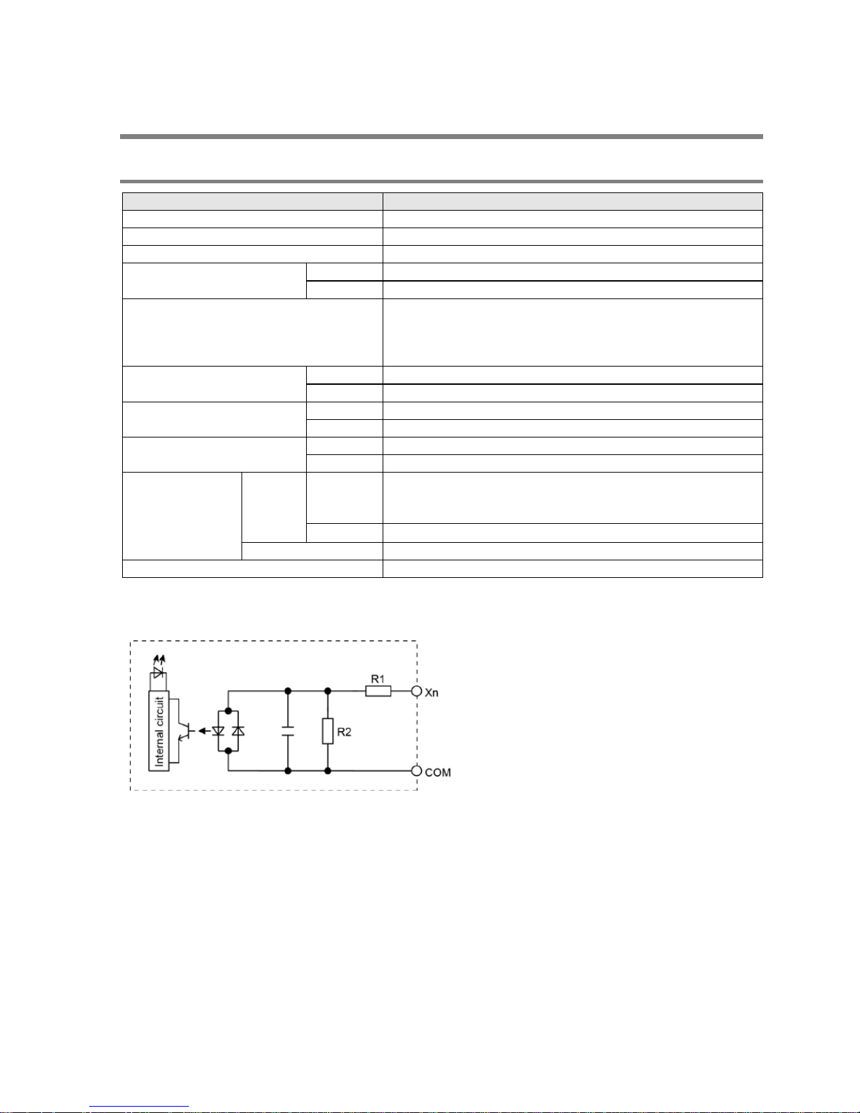
2.3 Input/Out put Spe ci fi cations
2.3.1 Input Specifications
Item
Description
Insulation method
Optical coupler
Rated input voltage
24V DC
Operating voltage range
21.6 to 26.4V DC
Rated input current
X0 to X3
Approx. 3.5 mA
From X4
Approx. 4.3 mA
In put points per common
8 points/common (L14R), 16 points/common (L30R)
24 points/common (L40R), 16 points/common x 2 (L60R)
(Ei ther th e positive or negative of the i nput power supply
can be connected to common terminal.)
Min. on voltage/
Min. on current
X0 to X3
19.2 V DC/3 mA
From X4
19.2 V DC/3 mA
Max. off voltage/
Max. off current
X0 to X3
2.4V DC/1 mA
From X4
2.4V DC/1 mA
Input impedance
X0 to X3
Approx. 6.8 kΩ
From X4
Approx. 5.6 kΩ
Response time
off→on
X0 to X3
Normal input: 1 ms or less
high-speed counter, pulse catch, interrupt nput settings:
25 µs or less (L14/L30), 10 µs or less (L40/L60)
Note)
From X4
1 ms or less
on→off
Same as above
Operating mode indicator
LED display
Note) T his s pecification i s applied when the rated input voltage is 24 V DC and the temperature is 25 °C.
Circuit diagram
For X0 to X3: R1=6.8 kΩ R2=820 Ω
From X4: R1= 5.6 kΩ R2= 1 kΩ
Phone: 800.894.0412 - Fax: 888.723.4773 - Web: www.clrwtr.com - Email: info@clrwtr.com
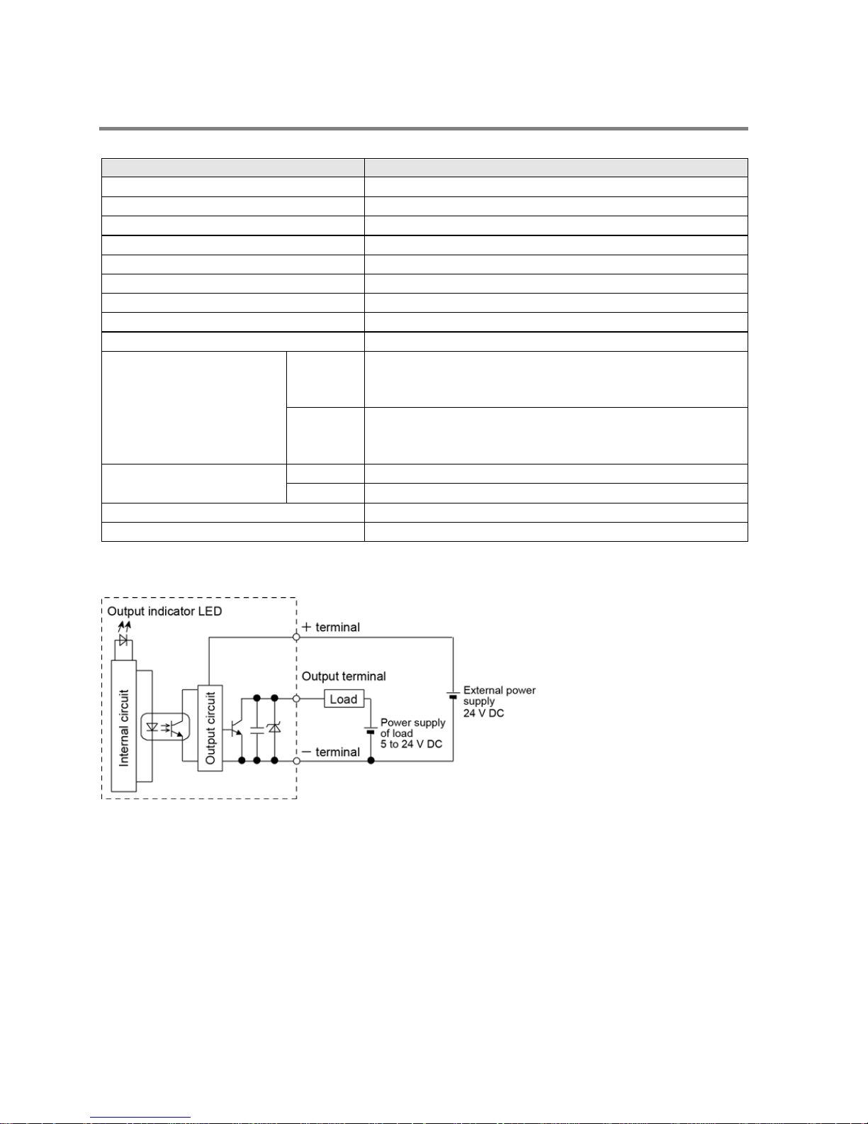
2.3.2 Output Specif ications (L14: Y0 to Y 1, L30/ L40/L60: Y 0 to Y 3)
Transistor (NPN) output
Item
Description
Insulation method
Optical coupler
Output type
Op en collector
Rated load voltage
5 to 24 V DC
Allowable load voltage range
4. 75 to 2 6.4 V D C
Max. load c urrent 0.5 A
Max. inrush curren t
1.5 A
Output points per common 2 points/common (L14), 4 points/common (L30/L40/L60)
Off state leakage current
1 µA or less
On s t ate volt age d rop 0.3 V DC or less
Response time
(at 25 °C)
OFF→ON
10 µs or less (L14/L30)
5 µs or less (L40/L60)
(Load current: at 15 mA or more)
ON→OFF
40 µs or less (L14/L30)
15 µs or less (L40/L60)
(Load current: at 15 mA or more)
External power supply
(+ and – terminals)
Voltage
21.6 to 26.4 V DC
Current
15 mA or less
Surge absorber
Zener diode
Operating mode indicator
LED display
Circuit diagram
Limitations on number of simultaneous output on points
No limitatio n
Phone: 800.894.0412 - Fax: 888.723.4773 - Web: www.clrwtr.com - Email: info@clrwtr.com
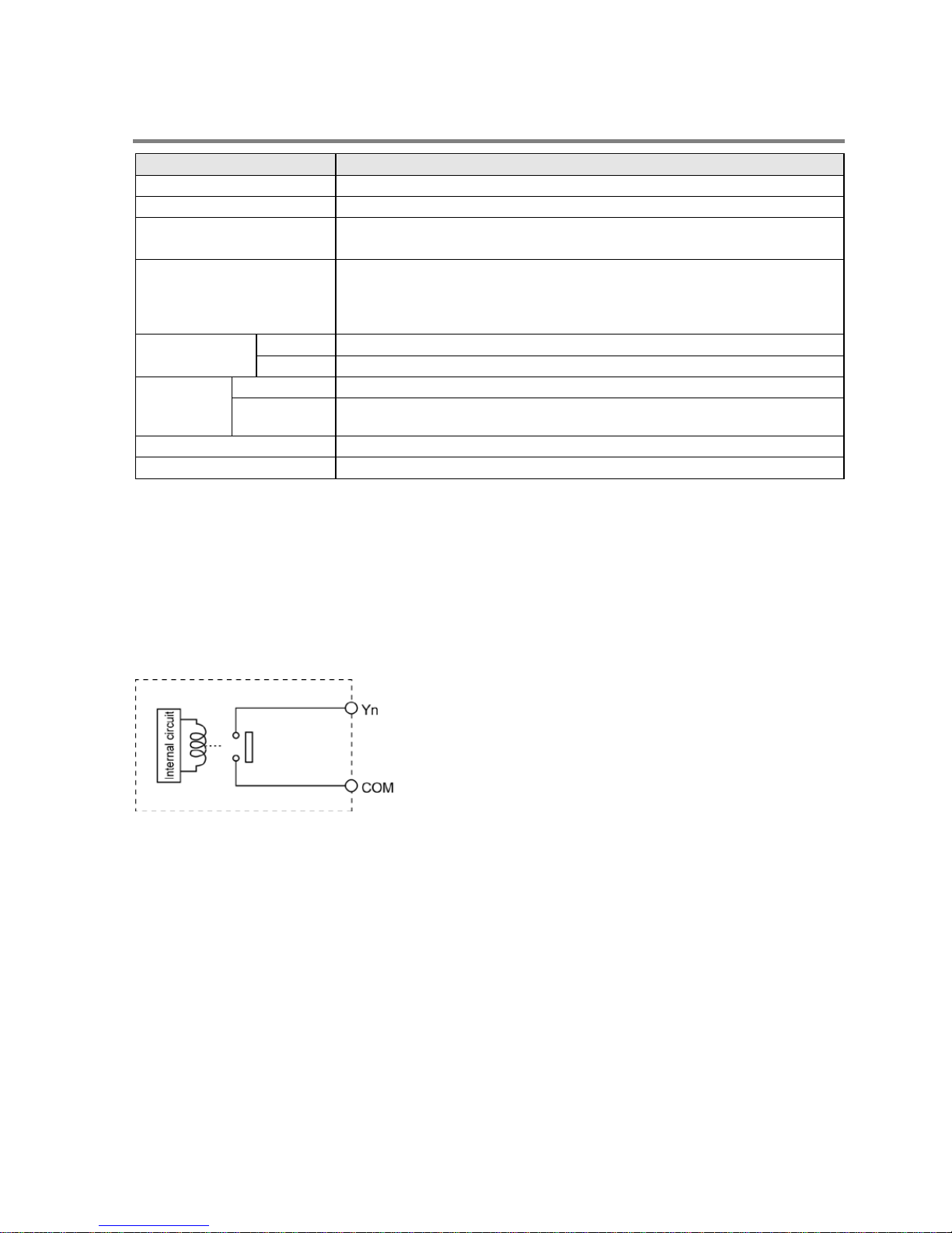
2.3.3 Output Specifications (L14: From Y2, L30/L40/L60: From Y4)
Item
Description
Insulation method
Relay insulation
Output type
1a output (Relay cannot be replaced)
Rated control capacity
(Resistance load)
Note)
2 A 250 V AC, 2 A 30 V DC (per point)
Output points per common
1 point/com mon x 2, 2 point s/comm on x 1 (L14)
2 point s/comm on x 1, 4 points/ common x 2 ( L30 )
1 point /com mon x 2, 2 point s/comm on x 1, 4 points/ common x 2 (L40)
4 points/common x 6 (L60)
Response time
off→on
Approx. 10 ms
on→off Approx. 8 ms
Lifetime
Mechanical
20 million times or more (Frequency of switching: 180 times/min.)
Electrical
100 thousand times or more (Frequency of switching at the rated control
capacity: 20 times/min.)
Surge absorber
None
Operating mode indicator
LED display
Note) There are restrict ions on the rated current for each o utput bl ock. Each usable rated current is as
below.
L14: Y2 to Y5 (4 points) Max. 6A in total
L30: Y4 to YD (10 points) Max. 8A in total
L40: Y4 to YFD (12 points) Max. 8A in total
L60: Y4 to YB (8 points) Max. 8A in total, YC to Y1B ( 16 points) Ma x. 8A i n t otal
Circuit diagram
Phone: 800.894.0412 - Fax: 888.723.4773 - Web: www.clrwtr.com - Email: info@clrwtr.com
2-8
2.4 Analog Input Specifications (For L40 and L60 types)
2.4.1 Common Specifications to Analog Input
Overview
- Two-channel analog inputs are available for FP-X0.
- You can select potentiometer (volume) input, thermister input or voltage input for each channel.
- Converted digital values are stored in special data registers.
Total accuracy
Input Specifications
Potentiometer
(Volume) input
Min. potentiometer resistance 5k
Resolution 10 bits (K0 to K1000)
Accuracy ±1.0% F.S. + External resistance accuracy
Thermister input
Allowable thermister resistance (External thermister min. resistance + External
resistance > 2k)
Resolution 10 bits (K0 to K1023) :
Accuracy ±1.0% F.S. + External thermister accuracy
Voltage input
Absolute max. input voltage 10V : Resolution 10 bits (K0 to K1023) :
Accuracy ± 2.5% F.S. (F.S. = 10V)
Special data register
Analog input channel
Potentiometer (Volume) input Thermister input, voltage input
Special data
register
Range of
values
Special data
register
Range of
values
CH0 DT90040
K0 to K1000
DT90044
K0 to K1023
CH1 DT90041 DT90045
Phone: 800.894.0412 - Fax: 888.723.4773 - Web: www.clrwtr.com - Email: info@clrwtr.com
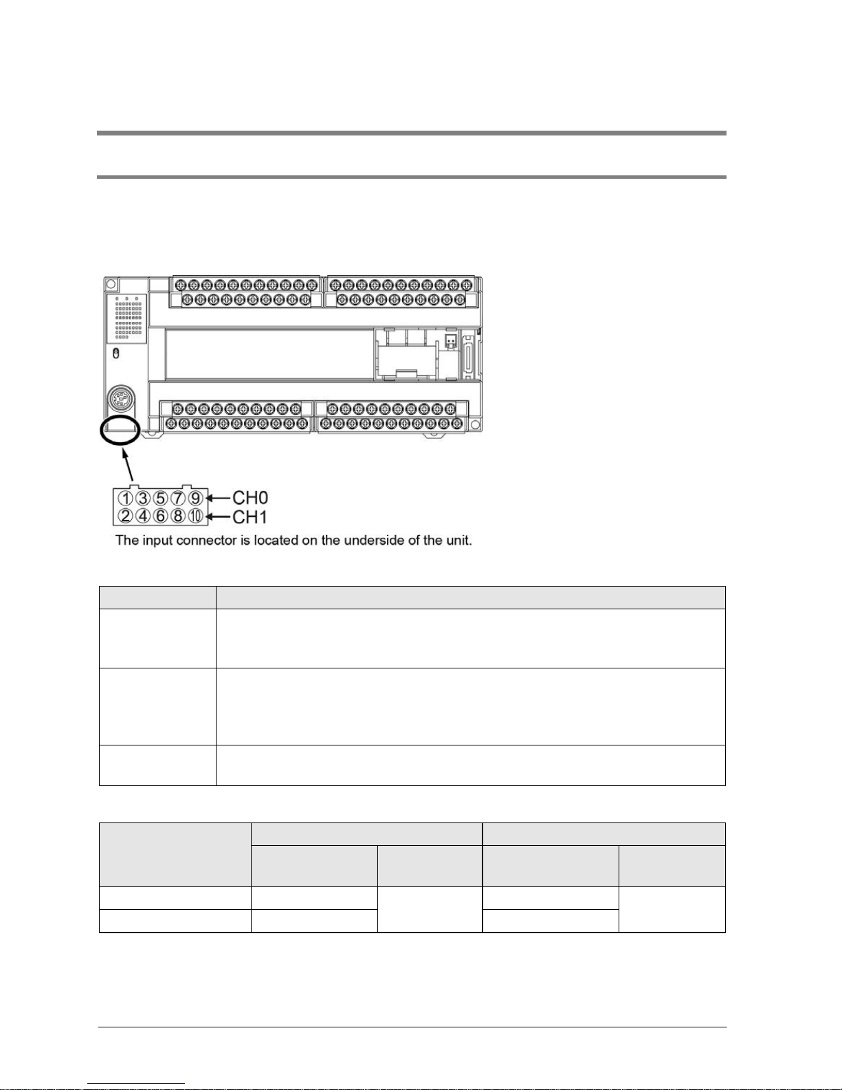
2.4.2 Connecti on of A nalog I n put Ca ble
Precautions on wiring
Note the following points, and make connection using the cable supplied with the unit.
- The wiring should be shorther t han 3 m.
- When removing the wire's insulati on, be careful not to scrat ch the core wire.
- Make sure stress is n ot appli ed to t he ca ble.
- Confirm the cable is connected properly before supplying power.
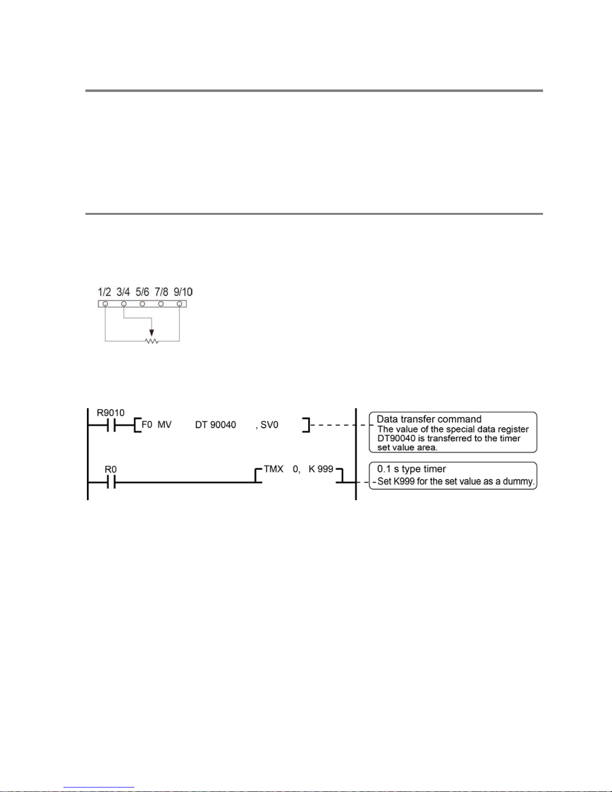
2.4.3 Potentiometer Input
Connect a potentiometer to the analog input connector externally. Values change in respo nse to the t urn
of the potentiometer.
Circuit diagram
- Do not connect anything with the 5/6 and 7/8 pins.
- Min. potentiomeneter res ist anc e s hould b e 5 kΩ.
[Example] Writing of the clock setting value
The value of the special data register (DT90040) that corre sponds to the analog inpu t CH0 is sent to the
set value area (S V0) of TMX0 to s et th e time for the clock.
Phone: 800.894.0412 - Fax: 888.723.4773 - Web: www.clrwtr.com - Email: info@clrwtr.com
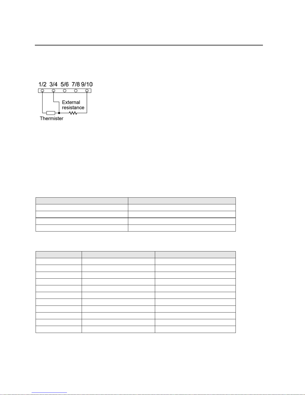
2.4.4 Thermister Input
Connect a thermister and resistor to the analog input connector externally to load the change in the
res ist anc e val ues of ther mi stor as ana log input values .
Circuit diagram
- Do not connect anything with the 5/6 and 7/8 pins.
- It i s recommend ed to use ap prox. 2 kΩ as external resistance.
Thermister resistance and digital conversion value
- Use th e fol l owing formula to convert th e t herm ister resi stance a nd digit al co nversion value.
- Digital conversion values vary between K0 and K1012.
1012 x R (kΩ)
Thermister resistanc e (kΩ) = ―――――――― − R (kΩ)
Digi tal value + 1
Connected thermister
[Examp le] R = 2 .2k
Ω
- Thermisters whose resistance is between 200 and 75kΩ can be used.
Type of thermister (B constant)
Reference of measuring range (°C)
3390K
-50 to +100 °C
3450K 50 to +150 °C
4300K
+100 to +200 °C
5133K +150 to +300 °C
Thermister measurement temperature - A/D conversion table
[Example] Thermister B constant : 3450K, external resistance: R=2.2k
Ω
Temperature (°C)
Thermister resistance (kΩ)
Digital value after conversion
50
4.3560
344
60 3.1470 421
70
2.3170
497
80 1.7340 573
90
1.3180
640
100 1.0170 690
110
0.7940
752
120 0.6277 797
130
0.5017
834
140 0.4052 865
150
0.3305
890
Note) The digital value does not include (Total accuracy of A/D converter with built-in microcomputer:
±5LSB) + (Thermister accuracy) .
Phone: 800.894.0412 - Fax: 888.723.4773 - Web: www.clrwtr.com - Email: info@clrwtr.com
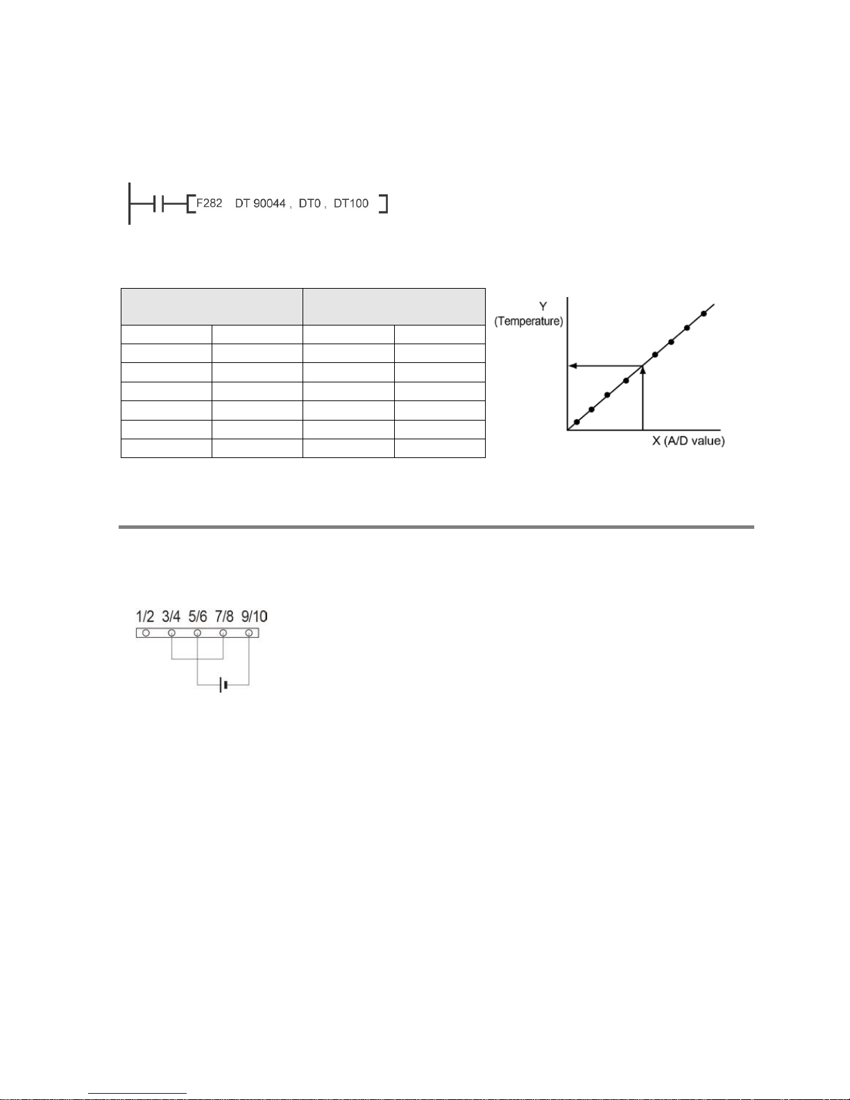
Conversion program using Scaling instruction (F282)
- Appropriately interpolated data can be obtained from nonlinear data by creating the data table of digital
values aft er conversion a nd tem perature an d execu ting t he scali ng instruction (F282).
DT90044
DT0
DT100
: Special data register
(Digital value after thermister input
conversion)
: Beginning of data ta ble
: Data after conversion (Temperature)
Example of data table
Input data (Digital value
after conversion)
Output data
(Temperature)
DT0
11
DT1 332 DT12 50
DT2
409
DT13
60
DT3 487 DT14 70
: : :
:
: : : :
DT11
878
DT22
150
Note) In DT0, specify the value of paired data.
2.4.5 Voltage in put
Connect the output line of a device to the analog input connector externally to perform voltage input.
Circuit diagram
- Do not connect anything with the 1/2 pin.
Voltage input value and digital conversion value
- Use the foll owing fo rmula to convert the volt age i nput value an d digit al conver s ion value.
(Digital conversion value + 1)
Voltage input value (V) = ―――――――――――――― x 10
1012
[Example] When digital conversion value is K900;
(K900 + 1)
Voltage input value (V)= ――――――― x 10 = 8.80V
1012
Input impedance
Approx. 1MΩ
Phone: 800.894.0412 - Fax: 888.723.4773 - Web: www.clrwtr.com - Email: info@clrwtr.com
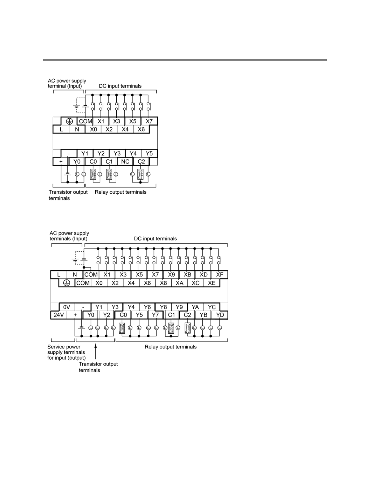
2.5 Terminal Layout
AFPX0L14R
AFPX0L30R
Note) Do not connect the service power supply terminals for input and other DC power supply in parallel.
Phone: 800.894.0412 - Fax: 888.723.4773 - Web: www.clrwtr.com - Email: info@clrwtr.com
 Loading...