

Page 1

PROGRAMMABLE CONTROLLERS
FP Web-Server
Hardware / Configurator
Page 2

Before beginning
Liability and copyright for the hardware
This manual and everything described in it are copyrighted. You may not
copy this manual, in whole or part, without written consent of Panasonic
Electric Works Europe AG (PEWEU).
PEWEU pursues a policy of continuous improvement of the design and
performance of its products. Therefore we reserve the right to change the
manual/product without notice. In no event will PEWEU be liable for direct,
special, incidental, or consequential damage resulting from any defect in
the product or its documentation, even if advised of the possibility of such
damages.
Limited warranty
We invite your comments on this manual. Please e-mail us at:
techdoc.peweu@eu.panasonic.com.
Please direct support matters and technical questions to your local
Panasonic representative.
If physical defects caused by distribution are found, PEWEU will
replace/repair the product free of charge. Exceptions include:
When physical defects are due to different usage/treatment of the
product other than described in the manual.
When physical defects are due to defective equipment other than the
distributed product.
When physical defects are due to modifications/repairs by someone
other than PEWEU.
When physical defects are due to natural disasters.
Page 3
DANGER
Indicates a hazardous situation which, if not
avoided, will result in death or serious injury.
WARNING
Indicates a hazardous situation which, if not
avoided, could result in serious or moderate injury.
CAUTION
Indicates a hazardous situation which, if not
avoided, could result in minor or moderate injury.
NOTICE
Indicates a property damage message.
Warnings used in this manual
One or more of the following warnings may be used in this documentation:
2 FP Web-Server V2.810 EN
Page 4

Table of contents
Table of contents
Getting started .......................................................................................................................... 8 1.
1.1 BEFORE YOU START ........................................................................................................................ 8
1.2 Product numbers and versions ............................................................................................................ 9
1.3 System requirements........................................................................................................................... 9
1.4 Advantages and functions of the FP Web-Server ............................................................................. 10
1.5 FP Web-Server block diagram .......................................................................................................... 14
1.6 System sample network .................................................................................................................... 14
Hardware description ............................................................................................................. 15 2.
2.1 The FP Web-Server unit .................................................................................................................... 15
2.1.1 Introduction ............................................................................................................................ 15
2.1.2 Hardware version .................................................................................................................. 16
2.1.3 FP Web-Server unit package ................................................................................................ 17
2.1.4 Parts and functions................................................................................................................ 18
2.1.5 Technical data ....................................................................................................................... 19
2.1.6 Installation ............................................................................................................................. 20
2.1.7 Important notes ..................................................................................................................... 21
2.1.8 Mechanical installation .......................................................................................................... 23
2.1.9 Connecting the power supply ................................................................................................ 27
2.2 FP Web expansion unit ..................................................................................................................... 28
2.2.1 Introduction ............................................................................................................................ 28
2.2.2 FP Web expansion unit package .......................................................................................... 28
2.2.3 Parts and functions................................................................................................................ 29
2.2.4 Technical data ....................................................................................................................... 29
2.2.5 Targeted peripheral list of the USB host port ........................................................................ 30
2.2.6 Important notes ..................................................................................................................... 30
2.2.7 Mechanical installation .......................................................................................................... 31
First steps ............................................................................................................................... 32 3.
3.1 Getting started ................................................................................................................................... 32
3.2 The Ethernet network ........................................................................................................................ 32
3.3 Connection of the FP Web-Server .................................................................................................... 32
3.4 Installation of the Configurator program ............................................................................................ 33
3.5 Determination of the IP configuration ................................................................................................ 33
3.6 Generate a new Configurator project ................................................................................................ 34
3.7 Transfer a Configurator project to the FP Web-Server ..................................................................... 36
3.8 Test the FP Web-Server with an Internet browser ............................................................................ 37
3.9 Further information ............................................................................................................................ 38
FP Web-Server V2.810 EN 3
Page 5

Table of contents
Configurator Software ............................................................................................................ 39
4.
4.1 General information on the FP Web-Server Configurator ................................................................. 39
4.2 Control buttons for administering the "Configurator Project" ............................................................. 41
4.3 Control buttons for the remote FP Web-Server unit .......................................................................... 41
4.3.1 Compare ................................................................................................................................ 42
4.4 System icon menu ............................................................................................................................. 43
Base configuration ................................................................................................................. 44 5.
5.1 Main settings ("Config") ..................................................................................................................... 44
5.1.1 Ethernet IP address ............................................................................................................... 45
E-mail setup ............................................................................................................................ 47 6.
6.1 E-mail functions of the FP Web-Server ............................................................................................. 47
6.1.1 E-mail function used for communication tests....................................................................... 48
6.1.2 E-mail server for LAN or Internet .......................................................................................... 49
6.1.3 How to find out the address of the e-mail server ................................................................... 50
6.2 E-mail tab input fields ........................................................................................................................ 51
6.3 E-mail via SSL ................................................................................................................................... 51
FTP client and SD memory card control setup .................................................................... 52 7.
7.1 FTP client function of the FP Web-Server ......................................................................................... 52
7.2 Operation modes for FTP client and SD card storage ...................................................................... 53
7.3 FTP client / SD memory card settings ............................................................................................... 56
7.3.1 Enable FTP client and SD memory card control ................................................................... 56
OpenVPN client ...................................................................................................................... 58 8.
8.1 OpenVPN client function of the FP Web-Server ............................................................................... 58
8.2 OpenVPN client settings .................................................................................................................... 59
8.2.1 Enable OpenVPN client ......................................................................................................... 59
Data logger setup ................................................................................................................... 61 9.
9.1 Data logger function .......................................................................................................................... 61
9.2 Log file and CSV file structure (default) ............................................................................................. 63
9.3 Log file and CSV file structure (individual format) ............................................................................. 65
9.4 Data logger tab input fields ................................................................................................................ 66
9.5 Configure log files .............................................................................................................................. 67
9.5.1 Log file details ....................................................................................................................... 67
9.6 Logging device setup ......................................................................................................................... 68
FPWEB Script ......................................................................................................................... 69 10.
10.1 FPWEB Script settings ...................................................................................................................... 69
10.1.1 Enable FPWEB Script ........................................................................................................... 69
4 FP Web-Server V2.810 EN
Page 6

Table of contents
10.1.2 Start PPP connection ............................................................................................................ 70
10.1.3 Start FTP transmission .......................................................................................................... 70
10.1.4 Start e-mail transmission ....................................................................................................... 71
10.2 FPWEB Script function of the FP Web-Server .................................................................................. 73
HTTP client .............................................................................................................................. 75 11.
11.1 HTTP client ........................................................................................................................................ 75
11.2 Cloud client ........................................................................................................................................ 76
11.3 HTTP client setup .............................................................................................................................. 78
11.3.1 Use Dynamic Server IP/Name .............................................................................................. 78
11.4 HTTP Client SSL Connection ............................................................................................................ 79
HTTP server functions/web pages ......................................................................................... 81 12.
12.1 Details on the FP Web-Server's web page functions ........................................................................ 81
12.1.1 Testing the FP Web-Server functions ................................................................................... 81
12.1.2 Internet browser settings ....................................................................................................... 82
12.1.3 Generalities on PLC data fields in HTML pages ................................................................... 83
12.1.4 HTTP address, CGI function PLC and calling parameter ..................................................... 84
12.1.5 Configurator settings concerning the HTTP server ............................................................... 85
12.1.6 Editing HTML pages .............................................................................................................. 86
12.1.7 Compiling and transferring HTML pages .............................................................................. 88
12.1.8 Data fields for displaying PLC data on HTML pages ............................................................ 88
12.1.8.1 Examples to display PLC data in an HTML page ................................................. 91
12.1.8.2 Comments ............................................................................................................ 94
12.1.9 Using variable names instead of absolute PLC addresses .................................................. 96
12.1.10 Access protection for individual HTML pages .......................................................... 99
12.1.11 Inputs for controlling PLC internal flags on HTML pages ....................................... 101
12.1.12 Defining input fields for PLC data on HTML pages ................................................ 101
12.1.12.1 Examples on PLC data entries via HTML page ................................................. 104
12.1.12.2 Notes on strings.................................................................................................. 106
12.1.12.3 Comments on defining input fields for PLC data on HTML ................................ 107
12.1.12.4 Extended Http POST functions .......................................................................... 107
12.1.13 Example on formatting display and input fields ...................................................... 109
12.1.14 Automatic page reload upon submitting PLC data ................................................. 112
12.1.15 Notes on XML files with PLC data .......................................................................... 114
12.1.16 ASCII character codes for strings ........................................................................... 115
12.2 Configurator HTTP administration and functions ............................................................................ 116
12.2.1 PLC access rights ............................................................................................................... 118
12.2.1.1 Configuration via HTML ...................................................................................... 118
12.2.1.2 MEWTOCOL communication via HTTP server .................................................. 119
12.3 Https server ..................................................................................................................................... 120
12.4 Improve performance of HTTP visualizations with PLC data .......................................................... 120
FP Web-Server V2.810 EN 5
Page 7

Table of contents
Ethernet and serial (RS232C, RS485, USB) ports .............................................................. 123
13.
13.1 General information on the Ethernet and serial ports ..................................................................... 123
13.1.1 Server .................................................................................................................................. 123
13.1.2 Client ................................................................................................................................... 125
13.1.3 FP Web-Server and PLC timeouts ...................................................................................... 127
Dial-in setup for PPP server ................................................................................................ 130 14.
14.1 Dial-in networking setup for computer/FP Web-Server ................................................................... 130
14.1.1 TCP/IP network installation of a Windows client ................................................................. 131
14.1.2 Modem and dial-up networking installation of a Windows client ......................................... 131
14.1.3 Setup of the modem connected to the FP Web-Server for PPP-communication ............... 138
14.1.4 FP Web-Server PPP gateway functions ............................................................................. 139
14.1.5 FPWIN Pro setup to use the remote dialup network ........................................................... 141
14.1.6 PPP communication via null modem cable ......................................................................... 142
14.2 Dial-in inputs and parameters for PPP server ................................................................................. 145
Dial-out setup for PPP client ............................................................................................... 146 15.
15.1 The Internet dial-out function ........................................................................................................... 146
15.1.1 Internet e-mail settings ........................................................................................................ 146
15.1.2 Notes for advanced users ................................................................................................... 149
15.1.3 When using a cellular phone (GSM) modem ...................................................................... 152
15.1.4 GPRS Internet connections ................................................................................................. 152
15.2 Internet dial-out settings .................................................................................................................. 154
NTP server for PLC clock synchronization ........................................................................ 155 16.
16.1 (S)NTP servers ................................................................................................................................ 155
Modbus functions ................................................................................................................ 157 17.
17.1 Overview over Modbus-TCP functions of the FP Web-Server ........................................................ 157
17.2 Modbus-TCP server of the FP Web-Server in general.................................................................... 158
17.3 Modbus-TCP client of the FP Web-Servers in general ................................................................... 160
17.4 Appendix for Modbus functions ....................................................................................................... 162
IEC 60870 functions of the FP Web-Server ......................................................................... 163 18.
18.1 IEC 60870 general functions ........................................................................................................... 163
18.1.1 Details of the IEC 60870 configuration: modem and multipoint settings............................. 164
18.2 Parameters for IEC 60870 ............................................................................................................... 167
18.3 IEC 60870 library for control FPWIN Pro ........................................................................................ 167
SNMP functions .................................................................................................................... 169 19.
19.1 Overview of SNMP on the FP Web-Server ..................................................................................... 169
19.2 Parameters for SNMP ..................................................................................................................... 171
6 FP Web-Server V2.810 EN
Page 8

Table of contents
19.2.1 SNMP Version ..................................................................................................................... 171
Additional information .......................................................................................................... 173 20.
20.1 Contents of the CD and auxiliary programs .................................................................................... 173
20.2 Description of the HTML examples ................................................................................................. 173
20.3 PLC connection, cable drawings, modem ....................................................................................... 174
20.3.1 PLC connection ................................................................................................................... 174
20.3.2 Cable drawings and modem ............................................................................................... 175
20.3.3 DIP switches ........................................................................................................................ 176
20.3.4 LEDs .................................................................................................................................... 178
20.3.5 Clearing passwords ............................................................................................................. 178
20.4 IP and TCP/IP .................................................................................................................................. 179
20.5 Setup of an individual Ethernet LAN ............................................................................................... 181
20.6 Preinstalled passwords and safety instructions .............................................................................. 184
20.7 Troubleshooting ............................................................................................................................... 186
20.7.1 Network communication problems ...................................................................................... 186
20.7.2 Problems finding an FP Web-Server unit or unable to send configuration ......................... 188
FP Web-Server V2.810 EN 7
Page 9

Getting started
Chapter 1
1.1 BEFORE YOU START
Please read the following notes on HTML. It will make working with the FP
Web-Server easier for you:
Make sure that you have worked through the First Steps (see p. 32) before
you try out the HTML functions of the FP Web-Server.
In order to use HTML you do not have to be able to tag or program HTML.
Various software is at your disposal:
Getting started
Word, Frontpage (delivered with MS Office) et.al. can serve as editors
for creating HTML files.
The created HTML file will be saved on the FP Web-Server with the help
of the Configurator.
A browser (e.g. Internet Explorer) is used to display the .htm file.
These software tools provide the logical markup (i.e. text parts are
automatically adjusted to any screen format without using a lot of
memory) and easy linking that define HTML.
Please refer to the respective software company for questions on software
not provided by Panasonic mentioned in this manual (or on the software
you chose to work with HTML).
There are two ways to create HTML files:
Simple: You use editors that translate data into HTML automatically.
When using these editors, you need no special knowledge about HTML.
Advanced: You create HTML files directly. You need to have knowledge
about HTML.
For the FP Web-Server you need to have basic knowledge on how to use
HTML.
8 FP Web-Server V2.810 EN
Page 10

In case you lack knowledge about HTML, Panasonic provides you with a
Item
Product name
Part number
FP Web-Server (Hardware)
FP WEB-SERVER UNIT
FP-WEB
(Japan: AFP0610)
FP WEB-SERVER2 UNIT
FP-WEB2
(Japan: AFP0611)
FP Web Expansion
(Hardware)
FP Web Expansion Unit
FPWEBEXP
Configurator Software
FP Web Configurator Tool
Ver.2.810
FPWEBTOOL2
(Japan:
AFPS30520-D)
FP Web Configurator Tool
Ver.2.810 Upgrade
FPWEBTOOLR2
(Japan:
AFPS35520-D)
Software for creating HTML
visualization for FP-WEB2
FP Web Designer
AFPS36510
brief introduction in the section First HTML Page Including PLC Data. In
addition, we have inserted examples on HTML (see "Description of the
HTML examples" on p. 173) on the CD (supplied with the FP Web-Server).
You can install and modify them easily without knowledge of HTML.
1.2 Product numbers and versions
Getting started
You can retrieve information on the following components by clicking on
the system icon (see p. 42) in the upper, left-hand corner and selecting
"About Configurator...":
Control FP Web Configurator Tool
Serial number
Name of owner and organization
The hardware version (see p. 16) is printed on the type plate of the FP
Web-Server.
1.3 System requirements
The FP Web Configurator Tool has the following system requirements:
FP Web-Server V2.810 EN 9
Windows® 7, Windows® 8.x or Windows® 10
Hard disk with at least 27MB free disk space
Color or monochrome monitor
Page 11

Getting started
Standard Internet browser (e.g. Microsoft Internet Explorer, Mozilla
Firefox, Google Chrome, Apple Safari, Opera) to display HTML pages
The user needs administrator rights on his computer to perform the
following actions:
Install or update the FP Web Configurator Tool
Define a default editor.
1.4 Advantages and functions of the FP Web-Server
The multifunctional FP Web-Server unit allows you to access FP Series PLCs
via Ethernet networks (Intranet and Internet) for data exchange.
Access can be carried out by a computer and a standard browser, such as
MS Internet Explorer Mozilla Firefox, Google Chrome, Apple Safari or
Opera, by specifying the target unit's IP address, which can be changed.
The HTML page can be generated with standard tools, such as Frontpage,
Dreamviewer or MS Word (not supplied with the Configurator). Panasonic
offers the FP Web Designer (Product Number: AFPS36510) for easily
designing HTML pages without any knowledge of programming languages
for HTML, PHP, Java or Javascript.
FP Web-Server advantages:
Use standard browser, save Scada software
Use existing Intranet, save wiring
Representation of PLC data in HTML pages
Value input and change of values in the PLC (set value, outputs,
internal flags) via HTML pages.
Password protection for access
E-mail send function (alternatively via Internet dialup), e.g. for the
alarm function (optionally with PLC data attachments)
Remote programming: remote access via modem (via Dial-up
Networking)
Data transfer: process control system, PLC programming, telemetry,
remote maintenance, monitored state function
Interfacing RS232C serial data via Ethernet, i.e. two FP Web-Servers
are used to send RS232C data via Ethernet
10 FP Web-Server V2.810 EN
Page 12
Getting started
Modem gateway functions to other PLCs equipped with an FP
Web-Server
FP Web-Server functions:
The FP Web-Server works as an interface between a LAN or a WAN network
(Internet/ Intranet) and all PLCs of the FP series. The following main
features are supported:
RS232C/ Ethernet interface: (see p. 123)
RS232C to Ethernet redirection/ conversion
Programming and visualization tools access via Ethernet
Optional: password protection and IP lock security
Optional: second, full transparent port
Web-Server: (see p. 81)
PLC data presented as HTML pages
Access via standard Internet browser
HTML entry field for PLC data exchange
Optional: password protection
Optional: PLC data display using Java applets
PLC data delivery as XML files
E-mail: (see p. 47)
PLC can send out an e-mail
PLC defined or pre-stored e-mail text
FP Web-Server V2.810 EN 11
Page 13

Getting started
E-mail sending via LAN or Internet dialup
Optionally with PLC data attachments
Modem/ Ethernet gateway: (see "Dial-in networking setup for computer/FP Web-Server" on p.
130)
FP Web-Server can be dialed-up via modem for local or network access
One remote gateway for multiple FP Web-Servers provided in a local
Ethernet network
Remote password handling
IEC60870 protocol (optional): (see p. 163)
IEC60870-5-101 standard telecontrol communication protocol via serial
interfaces
IEC60870-5-104 standard telecontrol communication protocol via
Ethernet
Optionally with modem support
Network Time Server: (see p. 155)
PLC real-time clock can be synchronized via NTP server
Modbus RTU/TCP functions: (see p. 157)
Modbus RTU master/slave functionality
Modbus-TCP client/server functionality
Modbus RTU/TCP gateway
MEWTOCOL/Modbus gateway
SNMPv1 agent: (see p. 169)
The SNMP agent (see p. 169) feature allows any SNMP management
system to exchange data with FP Web-Server devices via the Ethernet
using SNMP version 1 protocol.
FTP client: (see p. 52)
The FP Web-Server unit can be configured as an FTP client (see p. 52)
for sending user-defined, current PLC data or logged data to a remote
FTP server.
12 FP Web-Server V2.810 EN
Page 14

Getting started
Data logger: (see p. 61)
The FP Web-Server unit can log PLC data (see p. 61) and store it on the
optional SD memory card or send it via FTP (see p. 52).
Secure data transmission and authentication: (see p. 58)
The FP Web-Server unit can communicate via OpenVPN (see p. 58) to
get an encrypted and secure data transmission and authentication.
The FP Web-Server comes in an FP0 housing and has the following interfaces: (see "Hardware
description" on p. 15)
RS232C interface which can be connected to the PLC (MEWTOCOL
protocol)
Ethernet 10/100BaseT interface for network connections using the TCP/
IP protocol
2nd RS232C interface for an optional modem or for full transparent
Ethernet/ RS232C communication
The optional FP Web Expansion unit has the following functions:
USB 1.1 host port
RS485 port
Digital output
SD memory card slot
Configurator software (see p. 39)
A Windows program is supplied to make the configuration and the setup of
the FP Web-Server easy. This configuration program is called "Control FP
Web Configurator Tool". It helps the user to quickly set up and change the
following items, e.g.:
Automatic integration of PLC data into HTML pages
Preparation of pre-stored mail addresses and texts
TCP/ IP address and parameter configuration (DHCP is also possible)
Password and security setup
FP Web-Server V2.810 EN 13
Page 15
Getting started
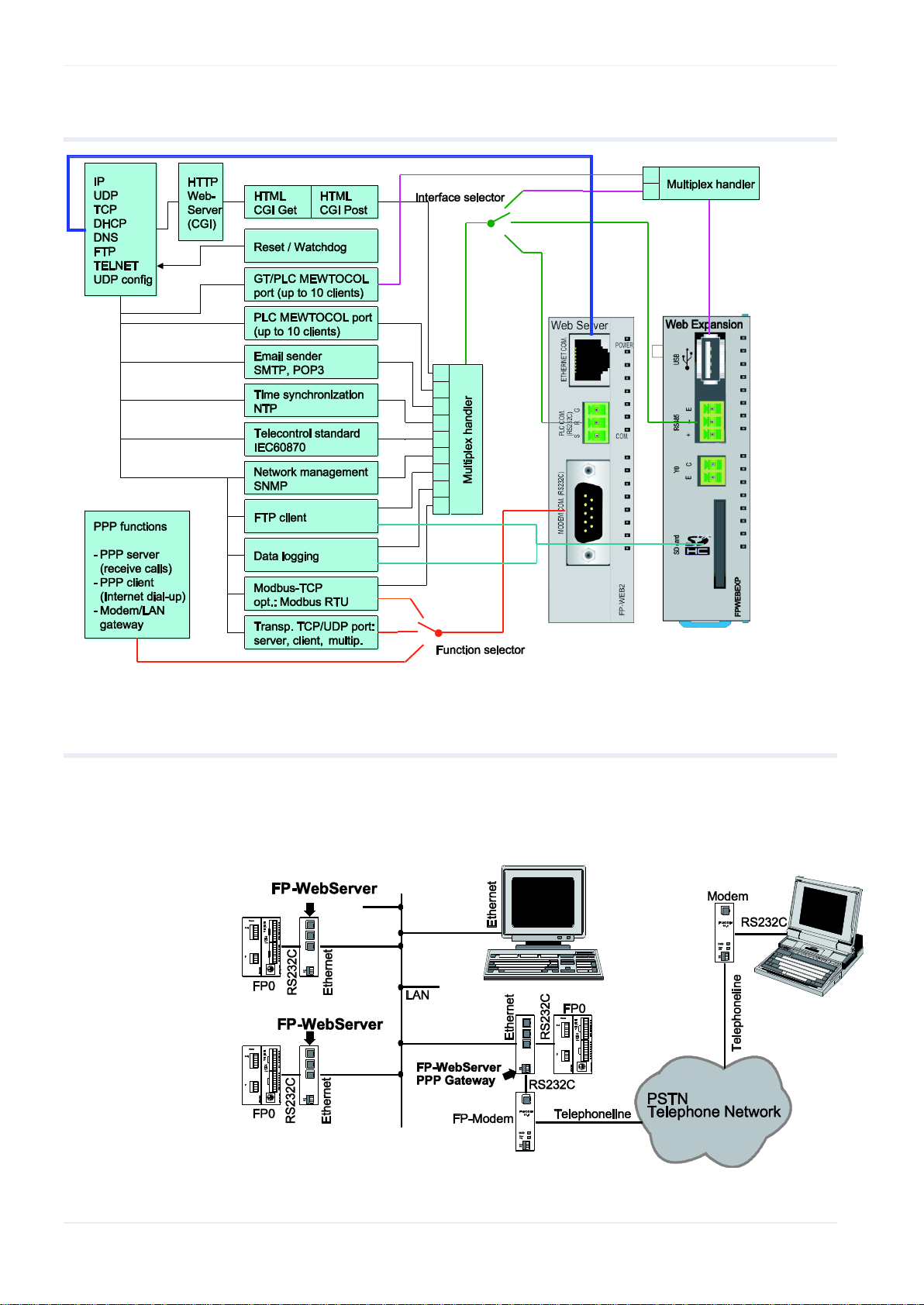
1.5 FP Web-Server block diagram
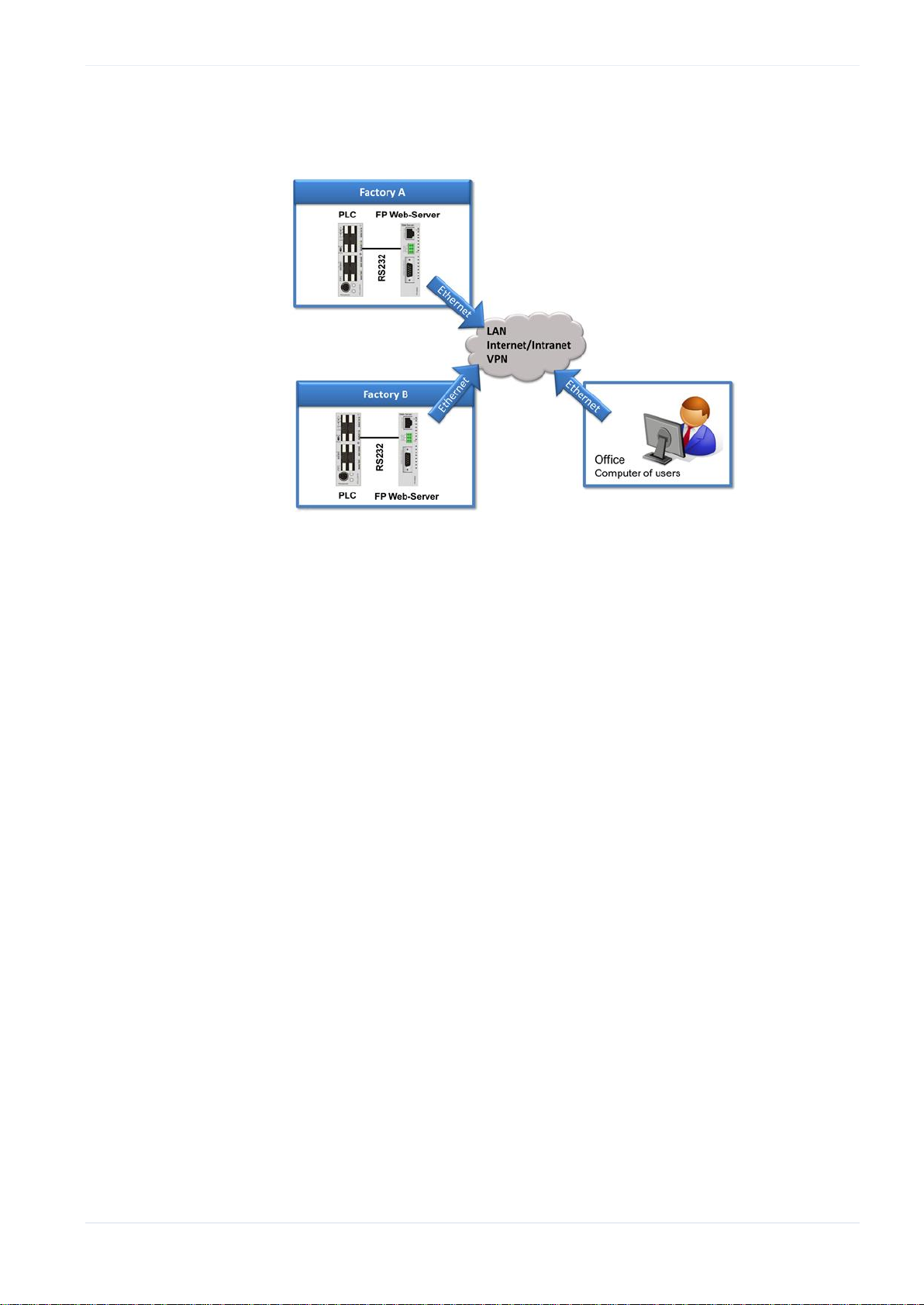
1.6 System sample network
Any combinations of the LAN and the dial-up functions are possible, e.g. an
Ethernet network connecting several FP Web-Servers with one FP
Web-Server set up as a gateway for the dial-up connections.
14 FP Web-Server V2.810 EN
Page 16

Chapter 2
Please read the safety instructions in important notes (see p. 21) and also
the section on mechanical installation (see p. 23) carefully.
Note
2.1 The FP Web-Server unit
2.1.1 Introduction
Hardware description
Hardware description
The FP Web-Server allows you to connect the Panasonic FP Series PLCs to
an Ethernet Network (LAN).
The FP Web-Server works as an Interface between a LAN or a WAN
network (Internet/ Intranet) and all PLCs of the FP Series.
The following main features are supported:
RS232C/ Ethernet Interface (remote programming monitoring and
visualization)
Web-Server (http/https server supplies HTML pages with PLC data (see
comments))
E-mail (SMTP protocol)
Modem/Ethernet gateway (PPP Server function)
Modbus-TCP/RTU functions
NTP time synchronization
Optional: IEC60870
SNMPv1 agent
FTP client, FTP server
Data logger (requires FP Web expansion unit)
A Windows program is supplied to make the configuration of the FP
Web-Server easy (see comments).
FP Web-Server V2.810 EN 15
Page 17

Hardware description
FP-WEB2
FP-WEB
Ethernet interface
100Mbps
10Mbps
Application memory
8MB Flash
0.5MB Flash
CPU speed
24 bits at 25MHz
16 bits at 20MHz
Comments:
See above for a more detailed overview (see p. 8) of the FP Web-Server
functions. There you can also find a block diagram, a list of features and a
brief description.
A data sheet can be found below which also lists the supported standards
and protocols.
A standard HTML editor (not supplied with the FP Web-Server
Configurator Tool) is needed to design HTML Web pages. HTML pages
can easily be created with the FP Web Designer (product number:
AFPS36510) without knowledge of HTML or any other programming
language.
A standard Internet browser, e.g. Microsoft Internet Explorer, Mozilla
Firefox, Google Chrome, Apple Safari, Opera, is recommended for
displaying the HTML pages.
2.1.2 Hardware version
The unit hardware model and version is printed on the type plate. Two
different hardware models are available:
Model 1: "FP Web-Server" unit (FP-WEB)
The hardware version 1.2 (available since 2003) is identical to hardware
version 1.1 except that the pin assignment of the 9-pin RS232C connector
was optimized and the UL approval sign is printed on the unit label.
Hardware version 1.3 (available since the beginning of 2006) is identical to
hardware version 1.2 but with the Panasonic logo and RoHS conformity.
Model 2: "FP Web-Server2" unit (FP-WEB2)
16 FP Web-Server V2.810 EN
Version 1.0 of this new hardware model has been available since December
2006.
The following table presents a brief comparison of the two models.
Page 18

Hardware version 1.01 has improved PLL circuitry on the CPU for a better
start-up behavior.
Hardware version 1.1 contains an additional right-side expansion connector
to support the FP Web expansion unit .
Comment:
The FP Web Configurator Tool (Ver.2.3 and higher) can configure all
available hardware types and versions.
2.1.3 FP Web-Server unit package
The FP Web-Server unit package of Panasonic contains:
Hardware description
Comments:
one FP Web-Server unit
a 24V DC power cable
a leaflet providing installation instructions
Phoenix 3-pin screw terminal
The FP Web-Server network will be configured via the Control FP Web
Configurator Tool.
The Control FP Web Configurator Tool can be purchased separately.
For creating HTML pages a standard HTML editor (not supplied with the
Configurator) is required.
FP Web-Server V2.810 EN 17
Page 19
Hardware description
Q
Ethernet (RJ45)
(Ethernet 10-Base-T / 100-Base-Tx) use Standard Ethernet CAT.5
W
RS232C (without handshake)
Screw terminal. Connects to the PLC.
E
2nd RS232C (SUB-D 9 male)
Compatible to IBM PC serial port.
Use standard serial computer cables.
– Connects to modem (PPP), or
– Transparent communication with 2
nd
PLC, computer, panel, etc.
R
24V DC, use Panasonic power cable
brown = +24V DC
blue = GND
green = framing ground
T
Connector for FP Web expansion unit
16-pin expansion connector
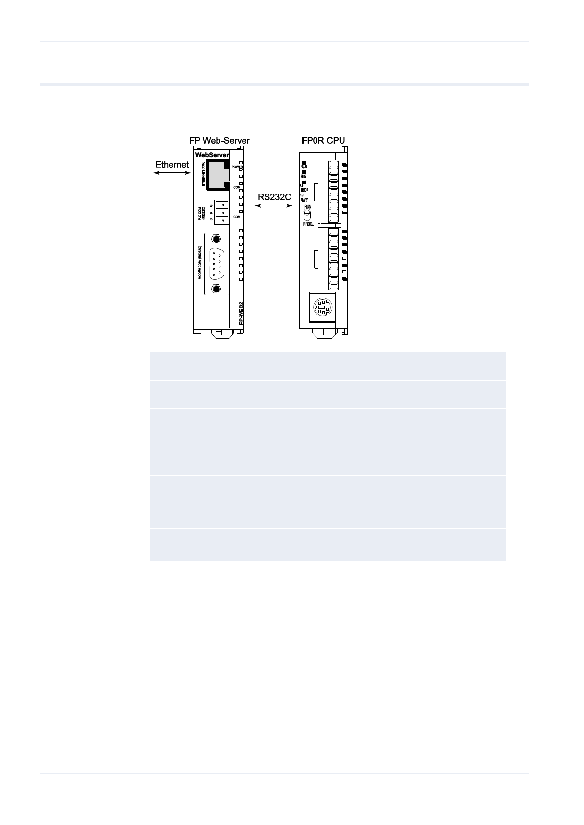
2.1.4 Parts and functions
Below are two illustrations of the FP Web-Server's parts and their
functions:
18 FP Web-Server V2.810 EN
Page 20

LEDs (see p. 177).
The expansion connector is for the FP Web expansion unit only.
FP0 expansion units are not supported and may damage the FP-WEB2
unit.
Only FP-WEB2 units with hardware version greater than 1.1 are
equipped with the connector for the FP Web expansion unit.
Feature
Description: Type 1
Type 2
Product number
FP Web-Server
PN Hardware: FP-WEB
PN Hardware: FP-WEB2
PN Configurator: FPWEBTOOL2
PLC connection
PLC COM: RS232C via 3-pin screw terminal port Plug:
Phoenix product: MC1,5/3-ST-3,5 Order Number: 18 40
37 9
Modem / 2nd
RS232C
Modem COM: RS232C via 9-pin SUB-D port, with RTS,
CTS Plug: 9-pin SUB-D female
Power supply
24V DC Molex 35 plug on the bottom side of the unit
Ethernet connection
Ethernet-COM: 10BASE-T
via RJ45 female connector
10BASE-T / 100BASE-TX
autoneg via RJ45 female
connector
LEDs (see p. 177)
Power, Ethernet, PLC data
exchange
Power, Ethernet, Ethernet
data, PLC data
Protocols and
standards
TCP/IP, UDP/IP, DHCP, FTP, TELNET, http, https, SMTP,
ESMTP-Auth, POP3, PPP, IEC60870, NTP, Modbus,
DynDNS, SNMPv1
Flash memory
512KBytes
8MBytes
For further information, refer to Available Memory
Calculation in the online help.
RAM
512KBytes
8MBytes
Operating voltage
24V DC (10.8 – 26.4V DC supplied by class 2 circuit
only)
Current consumption
Approx. 75mA at 24V DC
Approx. 65mA at 24V DC
Degree of protection
IP20
Ambient temperature
0°C to +55°C
Storage temperature
-20°C to +70°C
Humidity
Max. 30% to 85% (non-condensing)
Vibration resistance
10Hz to 55Hz, 1 cycle per minute with a double
amplitude of 0.75mm; 10 minutes every X-, Y-, and
Z-axis
Shock resistance
Min. 10g; 4 times every X-, Y-, and Z-axis
Dimensions
Height 90mm, Width 25mm, Depth 64mm
Note
2.1.5 Technical data
Hardware description
FP Web-Server V2.810 EN 19
Page 21

Hardware description
Feature
Description: Type 1
Type 2
Weight
Approx. 110g
Operating conditions
Free of corroding gases and excessive influence of dust
CE conformity
EMC Standard 89/336/EEC 1989EN 55022/Class B
EN 55022/Class B; EN 61000-4-2/A1; EN 61000-4-3
EN 61000-4-4 +A1:2010; EN 61000-4-6
UL approval
UL number "2LD7" (file E232530)
Hardware version
Refer to hardware version (see p. 16)
NOTICE
Be sure to install the FP Web-Server unit in locations designed for
electrical equipment, e.g. in a closed metal cabinet such as a
switch cabinet.
Make sure you are not electrostatically charged before you touch
the FP Web-Server or one of its units: the discharge of static
electricity can damage parts and equipment.
Procedure
2.1.6 Installation
Please install the FP Web-Server in the following order:
1. Mount the unit on the DIN rail on which the FP0R PLC is mounted
For detailed information, refer to mechanical installation (see p. 23).
2. Before connecting the power supply, please read the information on
power supply (see p. 27)
3. Connect the Ethernet (10/100BaseT) with a standard cable
4. Connect the PLC via RS232C/USB/RS485
Please read the information on wiring under PLC connection, cable
drawings, modem (see p. 174) or the "FP Web-Server Installation
Instructions Leaflet".
Configuration: For the first configuration and how to get started with
the Configurator, please refer to first steps (see p. 32).
20 FP Web-Server V2.810 EN
Page 22

The USB port and the RS485 interface are only available with the FP Web
Expansion Unit.
Note
2.1.7 Important notes
Please also see the Installation Instruction leaflet "FP Web-Server2 Unit"
supplied with your FP Web-Server for important notes, cables and
installation.
Hardware description
This is a brief description on how to put an FP Web-Server into
operation.
Please read the following notes carefully before installing your FP
Web-Server.
FP Web-Server V2.810 EN 21
Page 23
Hardware description
Avoid installing the unit in the following locations:
– Ambient temperatures outside the range of 0°C to 55°C/32°F to 131°F
– Ambient humidity outside the range of 30% to 85% RH
– Sudden temperature changes causing condensation
– Inflammable or corrosive gases
– Excessive airborne dust or metal particles
– Fuel, paint thinner, alcohol or other organic solvents or strong alkaline
solutions such as ammonia or caustic soda
– Excessive vibration or shock
– Direct sunlight
– Water in any form including spray or mist
Avoid noise interference from the following items:
– Influence from power transmission lines, high voltage equipment, power
cables, power equipment, radio transmitters, or any other equipment that
would generate high switching surges.
– If noise occurs in the power supply line even after the above
countermeasures are taken, it is recommended to supply power through an
insolated transformer, noise filter, or the like.
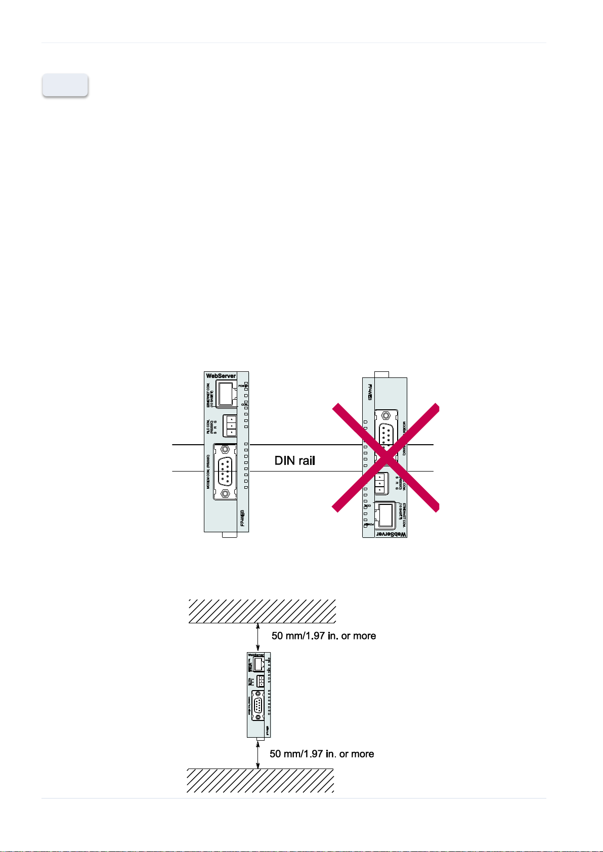
Measures regarding heat discharge:
– Always install the unit orientated with the Ethernet port facing outward on
the top in order to prevent the generation of heat.
– Do not install the unit above devices which generate heat, such as heaters,
transformers or large scale resistors.
Installation space:
– Leave at least 50mm/1.97in. of space between the wiring ducts of the unit
and other devices to allow heat radiation and unit replacement.
– Maintain a minimum of 100mm/3.937in. between devices to avoid adverse
affects from noise and heat when installing a device or panel door to the
front of the FP Web-Server unit.
Note
22 FP Web-Server V2.810 EN
Page 24
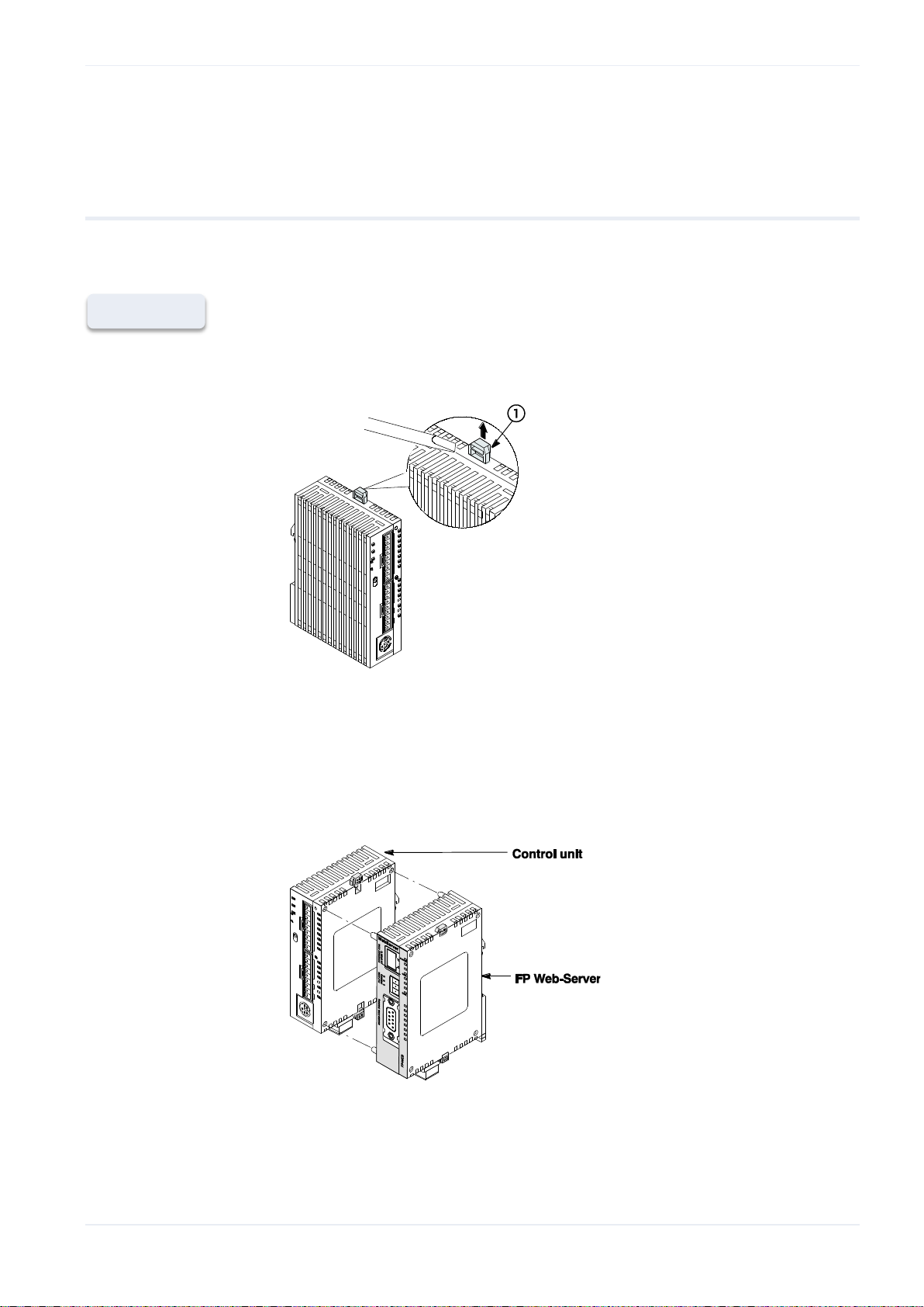
Procedure
2.1.8 Mechanical installation
a) Adding to FP0:
1. Raise the expansion hooks on the top and bottom sides of the unit with
a screwdriver
Hardware description
2. You can align the pins and holes in the four corners of the control unit
and expansion unit, and insert the pins into the holes so that there is no
gap between the units
However you need not necessarily connect the FP Web-Server in this
way.
Note:
FP Web-Server V2.810 EN 23
Make sure that the FP Web-Server is the last unit attached. Otherwise
the CPU cannot communicate with the expansion units.
Page 25
Hardware description
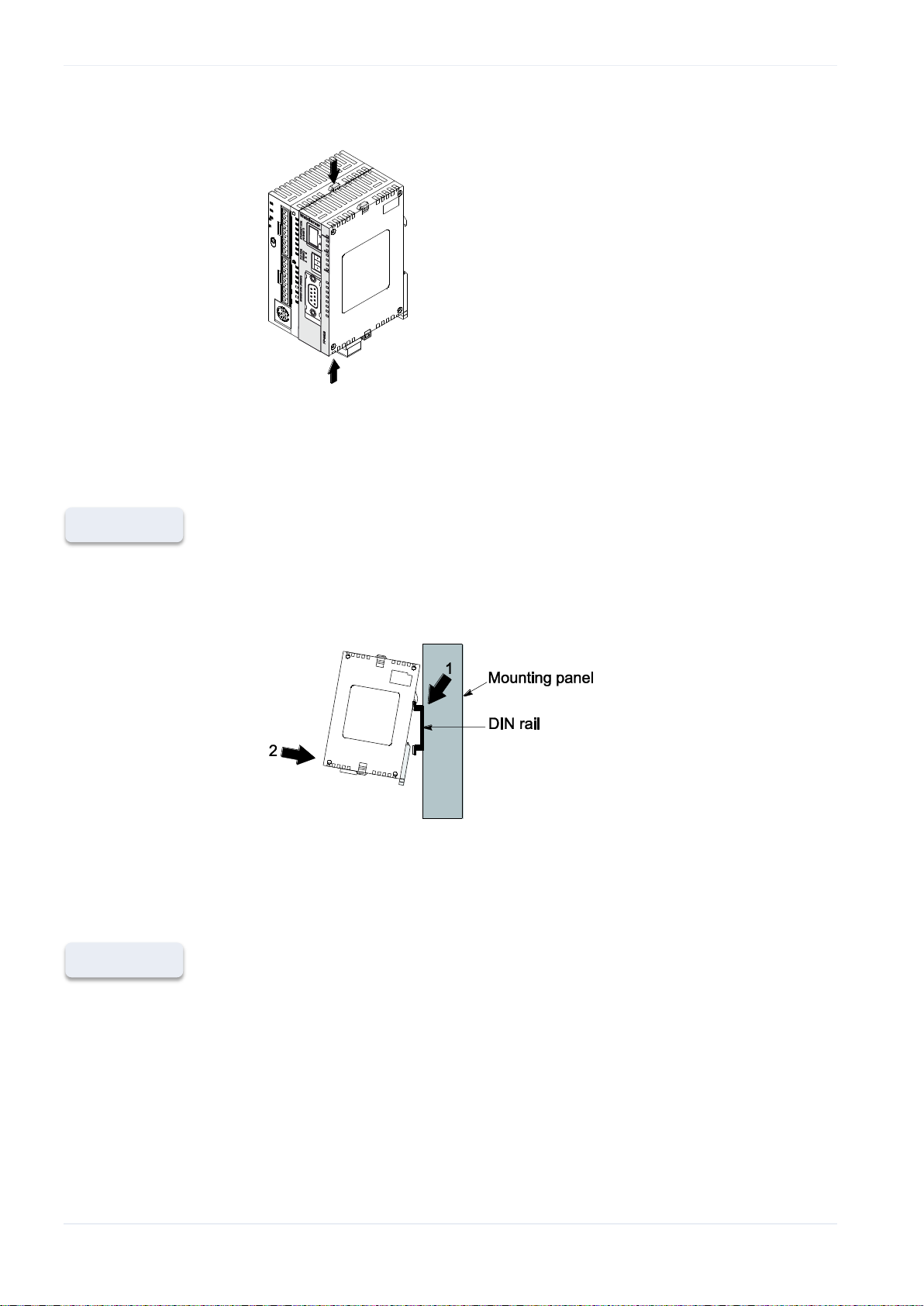
Procedure
Procedure
3. Press down the expansion hooks raised in step 2 to secure the unit
b) Attachment to DIN Rails:
The FP Web-Server unit enables a one-touch attachment to DIN rails.
1. Fit the upper hook of the FP Web-Server onto the DIN rail
2. Without moving the upper hook, press on the lower hook to fit the FP
c) Removal from DIN Rail:
You can easily remove the FP Web-Server as described below.
1. Insert a slotted screwdriver into the DIN rail attachment lever
Web-Server into position
24 FP Web-Server V2.810 EN
2. Pull the attachment lever downwards
Page 26
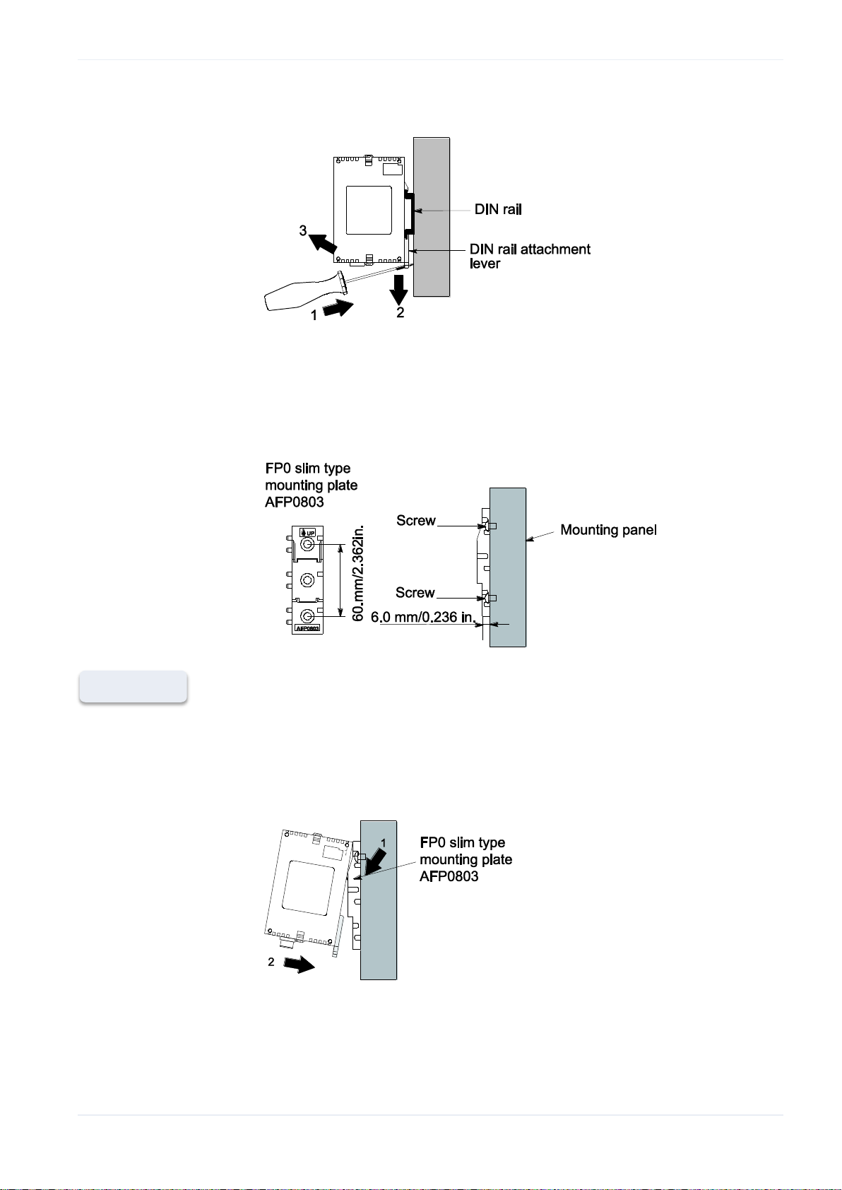
3. Lift up the FP Web-Server unit and remove it from the rail
Procedure
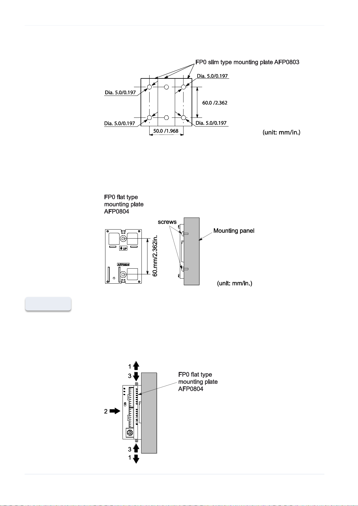
d) Installation Using FP0 Slim Type Mounting Plate
Use M4 size pan-head screws for attachment of FP0 slim type mounting
plate (AFP0803) to mounting panel.
Hardware description
1. Fit the upper hook of the FP Web-Server onto the FP0 slim type
mounting plate
2. Without moving the upper hook, press on the lower hook to fit the FP
Web-Server into position
When using an expansion unit, tighten the screws after joining all of the
FP0 slim type mounting plates to be connected. Tighten the screws at
FP Web-Server V2.810 EN 25
each of the four corners.
Page 27
Hardware description
Procedure
Example: Two Expansion Units
e) Installation Using FP0 Flat Type Mounting Plate
Use M4 size pan-head screws to attach FP0 flat type mounting plate
(AFP0804) and install according to the dimensions shown below.
1. Raise the expansion hooks on the top and bottom of the unit
2. Install the FP Web-Server on the FP0 flat type mounting plate
3. Align the expansion hooks with the plate and press the hooks back
down
26 FP Web-Server V2.810 EN
Page 28
Hardware description
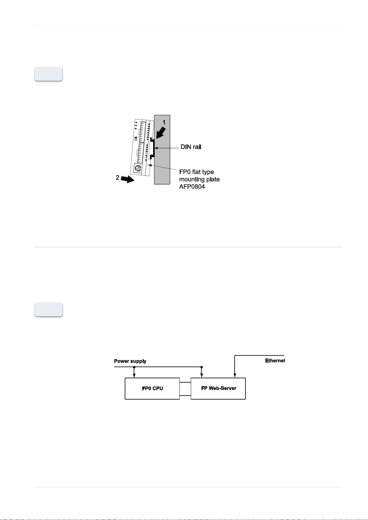
An FP Web-Server with an attached FP0 flat type mounting plate can also
be installed sideways on a DIN rail.
When connecting the power supply (class 2 circuit) make sure
the polarity (+/-) is correct.
The FP Web-Server unit and the PLC have to be supplied by THE
SAME power supply unit.
If power is supplied, the green POWER LED will be ON.
Framing Ground (FG) must be connected.
Please read the Important Notes (see p. 21).
Please also read the "FP Web-Server Leaflet" supplied with your
FP Web-Server.
Note
Note
2.1.9 Connecting the power supply
The FP Web-Server unit will turn ON as soon as the power supply has been
connected.
FP Web-Server V2.810 EN 27
Page 29

Hardware description
Please read the safety instructions in important notes (see p. 21) and also
the section on mechanical installation (see p. 23) carefully.
Note
2.2 FP Web expansion unit
2.2.1 Introduction
The FP Web expansion unit allows you to extend the interfacing possibilities
of the Panasonic FP Web-Server unit.
The following main features are supported:
USB/ Ethernet interface (remote programming monitoring and
visualization)
RS485/ Ethernet interface (remote programming monitoring and
visualization)
High-speed digital output
SD card slot
See the technical data sheet (see p. 29) for supported standards and
protocols.
2.2.2 FP Web expansion unit package
The package for the FP Web expansion unit contains:
FP Web Expansion unit
Leaflet providing installation instructions
Phoenix 3-pin screw terminal
Phoenix 2-pin screw terminal
Comments:
The FP Web expansion unit only works when connected to an FP-WEB2
unit.
The FP-WEB2 unit is configured via the Control FP Web Configurator
Tool.
The Control FP Web Configurator Tool can be purchased separately.
28 FP Web-Server V2.810 EN
Page 30
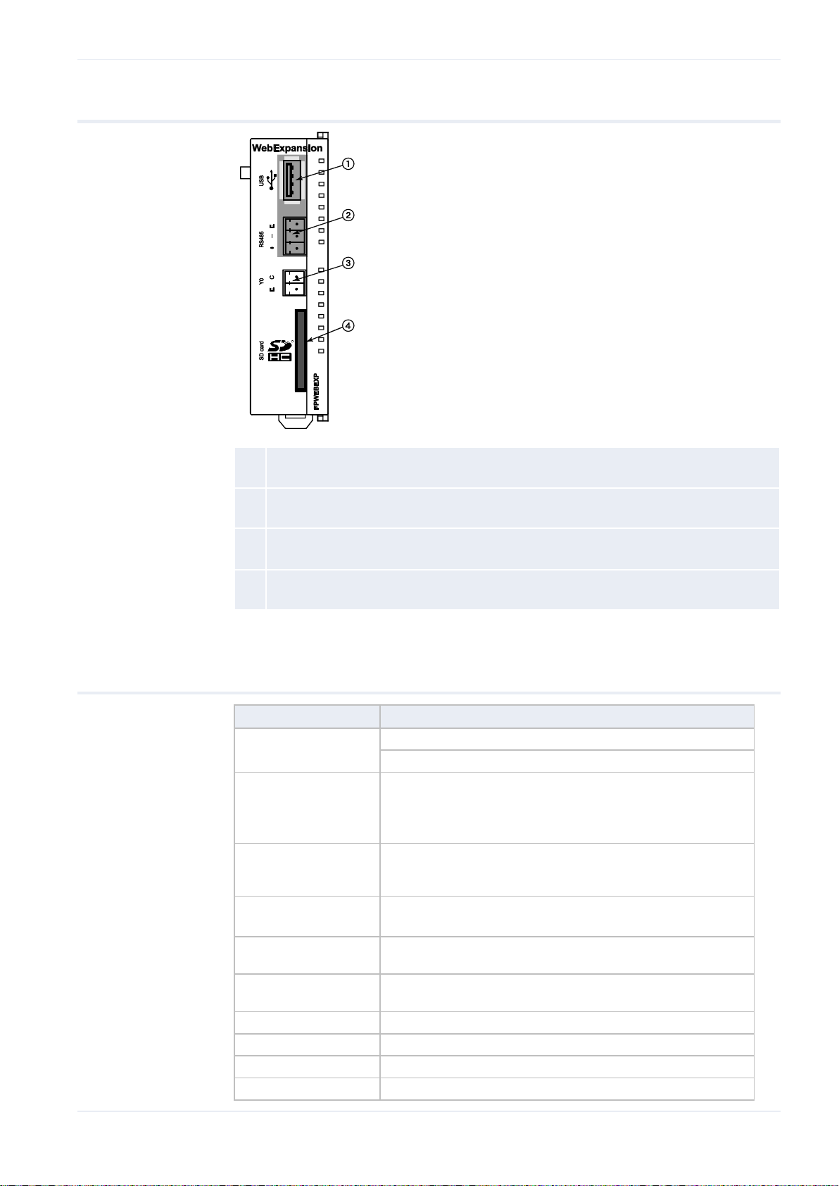
2.2.3 Parts and functions
Q
USB host port
USB 1.1 host port for Panasonic products that are supported by the FP-WEB2.
W
RS485
Screw terminal.
E
High-speed digital output
Optocoupler, phototransistor output.
R
SD card slot
SD/SDHC memory card support
Feature
FP Web Expansion Unit
Product number:
PN Hardware: FPWEBEXP
PN Configurator: FPWEBTOOL2
PLC connection
USB Port: USB 1.1 (refer to targeted peripheral list (see
p. 30))
RS485 via 3-pin screw terminal port plug: Phoenix
product: MC1.5/3-ST-3.5. Order number: 18 40 37 9
Digital output
High-speed digital optocoupler, phototransistor output
(5 to 24V DC, 50mA max., rise time:6µs or less, fall
time: 20µs or less)
SD/SDHC card slot
SD memory card supported (32M to 1GB)
SDHC memory card supported (4GB to 32 GB)
Operating voltage
3.3V DC (internal power supply via 16-pin expansion
connector from FP-WEB2)
Current consumption
Max. additional 20mA at 24V DC (depending on the SD
card used)
Degree of protection
IP20
Ambient temperature
0°C to +55°C
Storage temperature
-20°C to +70°C
Humidity:
Max. 30% to 85% (non-condensing)
Hardware description
2.2.4 Technical data
FP Web-Server V2.810 EN 29
Page 31

Hardware description
Feature
FP Web Expansion Unit
Vibration resistance:
10Hz to 55Hz, 1 cycle per minute with a double
amplitude of 0.75mm; 10 minutes every X-, Y-, and
Z-axis
Shock resistance:
Min. 10g; 4 times every X-, Y-, and Z-axis
Dimensions:
Height 90mm, Width 25mm, Depth 64mm
Weight:
Approx. 66g
Operating
conditions:
Free of corroding gases and excessive influence of dust
CE conformity:
EN 55022:2006 + A1:2007; Class B
EN 55024:1998 + A1:2001 + A2:2003; Class A
Hardware version
Refer to hardware version (see p. 16)
Manufacturer
Model
Vendor
ID
Product
ID
Description
Speed
Panasonic
Electric Works,
Ltd.
GT series
0x0986
0x0310
Panasonic GT
USB driver ver.
1.0
Full speed
Silicon
Laboratories,
Inc.
CP2101 USB
to UART
Bridge
Controller
0x10C4
0xEA60
Panasonic FP-X
series USB
driver
Full speed
2.2.5 Targeted peripheral list of the USB host port
The USB host port of the FP Web expansion unit supports FP-X PLCs and
GT series HMIs. More details can be found in the following targeted
peripheral list.
2.2.6 Important notes
Please also see the installation instruction leaflet supplied with your FP Web
expansion unit for important notes, cables and installation.
To prevent malfunction or failure, please refer to the important notes (see
p. 21) for the FP Web-Server concerning the installation environment and
space.
30 FP Web-Server V2.810 EN
Page 32

2.2.7 Mechanical installation
Refer to the installation instructions leaflet provided with the product for
instructions on:
Connecting the FP Web expansion unit to the FP Web-Server2 unit
Installing the units on a DIN rail.
Reference
For a detailed procedure about one-touch attachment to DIN rails, removal
from DIN rails, installation using FP0 Slim Type Mounting Plate or FP0 flat
type mounting plate, refer to the mechanical installation (see p. 23)
instructions of the FP Web-Server unit.
Hardware description
FP Web-Server V2.810 EN 31
Page 33

First steps
Refer to the e-mail function of the FP Web-Server (see p. 47) for an easy start.
For details on programming e-mail support on the PLC, refer to the
PEW_FPWEB library and its online help.
For further information, refer to Ethernet/serial (RS232C, RS485, USB) ports
(see p. 123).
Reference
Chapter 3
3.1 Getting started
This section describes putting the FP Web-Server into operation for the first
time. The subsequent step-by-step example depicts the general
configuration and use of the FP Web-Server for displaying HTML pages.
First steps
3.2 The Ethernet network
The FP Web-Server is supplied with a 10/100BaseT Ethernet connection.
This type of Ethernet network uses a peer-to-peer connection with twisted
pair cables. To establish a network, hubs and switches are used to connect
the participants in a star-shaped manner.
To be able to configure the FP Web-Server, a Windows computer with an
Ethernet network interface card has to be connected to the same network
as the FP Web-Server. The FP Web-Server can be connected to an existing
Ethernet network.
It is also possible to set up a separate network for the FP Web-Server. The
computer can also be directly connected to the FP Web-Server by using a
special "cross-over" Ethernet cable (see p. 181).
3.3 Connection of the FP Web-Server
For an initial function test (without the PLC data), the FP Web-Server has
to be connected to the Ethernet and be supplied with operating voltage
(24V DC and FG).
32 FP Web-Server V2.810 EN
Page 34

In the second step, the FP Web-Server has to be connected to the PLC (via
Please remember the ID number found on the FP Web-Server's type label.
You will need it when you configure the Web-Server.
Note
RS232C). The RS232C setting of the PLC must correspond to that of the FP
Web-Server. This setting can be defined in the PLC program (FPWIN Pro)
under the system parameter settings.
3.4 Installation of the Configurator program
First steps
Further information:
To be able to configure the FP Web-Server, a Windows computer with an
Ethernet network interface card has to be connected to the same network
as the FP Web-Server. The computer must be configured in such a way
that it supports the TCP/ IP network protocol.
To install the Configurator (administrator rights are needed), start the
setup program on the CD and follow the instructions of the installation
program "Control FP Web Configurator Tool". Various examples (see
"Description of the HTML examples" on p. 173) and HTML pages are
installed along with the Configurator. In addition, the tool DnsDisp.exe,
which locates DNS addresses of an Internet Service Provider (ISP), is
copied to the installation folder.
Contents of the CD and Auxiliary Programs (see p. 173)
The Configurator can be started in the Windows start menu under
Program files Panasonic-ID SUNX Control FP Web
Configurator 2 FP Web Configurator 2.
3.5 Determination of the IP configuration
Every Ethernet participant must have an individual IP address. This address
may not be used a second time in the same network. The IP address (see
p. 179) consists of 4 numbers (0 to 255). The first numbers define the
FP Web-Server V2.810 EN 33
Page 35

First steps
Procedure
network address, the other numbers define the participant's address. The
IP address of the FP Web-Server can be fixed or it can be allocated
dynamically by a DHCP-Server.
1. In a "self set-up" network (e.g. with only one hub) the IP addresses can
be assigned by yourself
In this case, do not use DHCP. For further information refer to Setup of
an Individual Ethernet LAN (see p. 181).
2. If the FP Web-Server is to be connected to an existing network, the
following data must be obtained from the network administrator:
Is there a DHCP-Server in the network? If NOT:
IP address: Which fixed IP address can be assigned to the FP
Web-Server?
Netmask: How is the network address set up (length of the network
address and/or the participant's address)?
Gateway: What is the gateway's IP address? (0.0.0.0 if there is no
gateway to be used).
3.6 Generate a new Configurator project
After having started the Configurator, a Configurator project can be opened
from the local hard drive with [OPEN]. A Configurator project consists of:
the configuration,
the e-mail texts, and
the HTML pages.
Upon the initial start, the "default_project" is automatically offered with
[OPEN]. With [OPEN] you can also load one of the examples (see
34 FP Web-Server V2.810 EN
"Description of the HTML examples" on p. 173). You can save it under a
new name with [SAVE AS]. On the "Config" page you can adjust the
following, most important settings. You must configure at least the
following:
The IP configuration (see "Determination of the IP configuration" on p.
33) has to be entered according to the destination network.
Page 36

First steps
The serial interface parameter used by whatever functions have been
configured. the PLC may have to be adjusted (RS232C, 19200 8O1 is
pre-adjusted).
It is also recommended to enter an individual user name and a
password of your own.
The HTTP server has to be activated for this initial test (please turn off
e-mail and PPP!):
For the initial test, no other parameters have to be altered. Save the
changed project with [SAVE].
Comments:
To receive additional help and information on the various Configurator
entries, please move the cursor to the respective input field and press
<F1>.
The "default_project" works without PLC data, i.e. it does not need to
be connected to the FP Web-Server. Nevertheless, in case "Example First web page with PLC data" is used, a PLC should be connected.
FP Web-Server V2.810 EN 35
Page 37

First steps
3.7 Transfer a Configurator project to the FP Web-Server
Use [FIND] to search the network for all FP Web-Servers. A list of all FP
Web-Servers found will be displayed. Please select the ID number of the
respective FP Web-Server (double-click or press <ENTER>).
If the FP Web-Server is put into operation for the first time (or a new
version of the Configurator has been installed), please initialize the FP
Web-Server ONCE before transferring the project, i.e. click [INITIALIZE]
and answer the safety request with [YES].
As there are HTML pages required for this initial test, the check box "Web
files" should be activated. With [SEND] you can transfer the project
(configuration plus HTML pages) to the respective FP Web-Server.
Please click [REBOOT] after transmission. Wait a little bit and then click
[FIND] again to make sure that the FP Web-Server is online again and to
find out which IP address it is using.
Comments:
Please memorize the IP address for the following tests with the browser
below.
If the FP Web-Server was configured with the wrong fixed IP address, a
query with [FIND] will result in an error message.
36 FP Web-Server V2.810 EN
Page 38

First steps
If an error message is displayed, click [YES]. This sets the FP
Web-Server to the IP address entered in the current Configurator
project. After a short waiting period, click [FIND] again.
If the current password of the FP Web-Server is not the same as the
password of the project, the user name and the password are requested
before transmission and/or restart ([SEND], [INITIALIZE], [REBOOT]).
Please refer to "Trouble Shooting (see p. 185)" if any problems occur
with the functions FIND, SELECT, INITIALIZE or SEND.
3.8 Test the FP Web-Server with an Internet browser
The HTML pages of the FP Web-Server can be displayed with a standard
Internet browser. Start the Internet browser and enter the IP address of
the FP Web-Server into the address field.
The HTML page "main.htm" of the FP Web-Server will be displayed. For
the "Default_Project" (without PLC data, FP Web-Server may not be
connected to a PLC) for example:
FP Web-Server V2.810 EN 37
Page 39

First steps
Comments:
Or for "Example - First web page with PLC data" (with PLC data):
Main.htm has the following restrictions: You cannot use PLC data items
and you cannot use password protection.
If the FP Web-Server is operated in an office network with a Proxy
gateway to the Internet, accessing the FP Web-Server HTML pages
might take a long time. In this case, shut off the Proxy function of the
browser for this specific IP address of the FP Web-Server. For the
browser setup also refer to TCP/IP Setup: Configurator/Browser
Operations Via LAN.
3.9 Further information
Details on FP Web-Server's web page functions (see p. 81)
The PLC sends e-mails (alarm e-mails with FPWIN Pro library (see p.
47))
Details on Ethernet/serial (RS232C, RS485, USB) ports (see p. 123)
Dial-up networking setup for computer and FP Web-Server (see "Dial-in
networking setup for computer/FP Web-Server" on p. 130)
IEC 60870 functions of the FP Web-Server (see p. 163)
38 FP Web-Server V2.810 EN
Page 40

Configurator Software
Chapter 4
Configurator Software
4.1 General information on the FP Web-Server Configurator
The FP Web Configurator administers "Configurator projects". These consist
of:
FP Web-Server project file (FP-Web.fpw)
FP Web-Server configuration (CHIP.INI file)
IEC 60870 configuration (mew60870.ini)
E-mail texts (MAIL_x.TXT files)
Data logger setting files (pewlog1.bin, pewlog2.bin)
Web files (MAIN.HTM; *.HTM; *.GIF; *.JPG; *.XML ...)
Certificate files for https
Every Configurator project is stored in a separate folder. A project consists
of e-mail text files, .INI text files and a sub-folder "http" in which all the
Web pages for the FP Web-Server are stored.
There are 3 ways to start the FP Web Configurator:
1. Start Program Files Panasonic-ID SUNX Control FP Web
Configurator 2 FP Web Configurator 2
2. Double-click the project file *.fpw of the project within the file explorer
3. Via a console command line that includes the configuration to be
opened
Select Start Run
FP Web-Server V2.810 EN 39
Page 41

Configurator Software
Enter e.g.: C:\Program Files (x86)\Panasonic-ID SUNX Control\FP Web
Configurator 2\FP Web Configurator 2\FPWebConfigurator.exe
Example - AJAX basics\FPWEB_AJAX\FP-Web.fpw
To administer ([OPEN], [SAVE]...) "Configurator projects", edit the
configuration (including e-mail texts and Web files) and to control the FP
Web-Server (transmission of files, initialization, reboot...), the FP Web
Configurator provides the following main components:
Control buttons (see p. 39)
Base configuration (see p. 44)
E-mail configuration and texts (see p. 47)
Web files and editor call (see p. 81)
Ethernet/Serial (RS232C, RS485, USB) ports configuration (see p. 123)
PPP server configuration (see p. 130)
IEC 60870 functions of the FP Web-Server (see p. 163)
PPP-Client Dial-Out (see p. 153)
NTP-Time (see p. 155)
Modbus functions (see p. 157)
SNMP functions (see p. 169)
FTP client functions (see p. 52)
Data logger functions (see p. 61)
and some more...
40 FP Web-Server V2.810 EN
Page 42

Configurator Software
In the following sections, the individual command buttons of the first page
("Project" page) of the Configurator are described in detail:
4.2 Control buttons for administering the "Configurator Project"
For a detailed description of the control buttons, refer to the online help
under the respective keyword of the button.
4.3 Control buttons for the remote FP Web-Server unit
FP Web-Server V2.810 EN 41
Page 43

Configurator Software
4.3.1 Compare
For a detailed description of the control buttons, refer to the online help
under the respective keyword of the button.
[Compare] will download the configuration file of the project from the
remote unit to the local disk. When the download is completed, the file will
be compared with the opened project configuration file. The number of
found differences will be shown in a little message box. Max. 8 (normally 5)
messages will be shown in the message box. An indication for more
differences is the '...' at the end of the message box. The value showed in
the message box (e.g. RS485 baud rate: 19200) is always the setting of
the remote unit.
Not all configuration parameters will be compared. Here is a list of
parameters that will NOT be compared:
Security settings (like user name, password, iplock etc.)
IEC60870 settings (only enable will be compared)
Datalogger log file settings
FPWEB Script file
E-mail texts
After the comparison is finished, the downloaded configuration file will be
deleted automatically.
42 FP Web-Server V2.810 EN
Page 44

4.4 System icon menu
Click the system icon on the title bar to open a menu, e.g. to:
change the user interface language of the FP Web Configurator
open a comment dialog
find out the software version
Configurator Software
FP Web-Server V2.810 EN 43
Page 45

Base configuration
Chapter 5
5.1 Main settings ("Config")
The main settings for the FP Web-Server are adjusted on the "Config" tab.
An Ethernet IP address (see p. 45) must be entered.
The parameters for the PLC interface may have to be adjusted (the
following figure shows the default settings).
We recommend that you specify a user name and password.
An additional static 2nd LAN IP address for the FP Web-Server unit can
be set, DNS can be enabled, the system restart function of the
Base configuration
FP-WEB2 can be activated and FTP access to the SD memory card of
the FP Web expansion unit can be restricted.
44 FP Web-Server V2.810 EN
Page 46

5.1.1 Ethernet IP address
Procedure
Every Ethernet participant must have an individual IP address. This address
may not be used a second time in the same network. The IP address
consists of 4 numbers (all numbers must be between 0 and 255, see also
IP and TCP/ IP (see p. 179)). The first numbers define the network
address, the other numbers define the participant's address.
Base configuration
The IP address of the FP Web-Server can be fixed or it can be allocated
dynamically by using a DHCP-Server.
1. In a "self set-up" network (see p. 181) (e.g. with only one switch), you
can assign the fixed IP addresses yourself
In many cases a class C network is used. The network is identified by 3
numbers. The participants (computers, units, FP Web-Server...) are
distinguished by the last number (1 to 254), e.g. 192.168.206.1 to
192.168.206.254.
If this network is connected to a second network via a gateway (e.g.
the computer for configuration might be in this network), the gateway
address also needs to be specified, e.g.:
Computer in x.y.206.z network with netmask 255.255.255.0, using the
x.y.206.1 gateway.
FP Web-Server in x.y.60.z network with the following settings:
FP Web-Server V2.810 EN 45
IP Add=x.y.60.31
Netmask=255.255.255.0
Gateway=x.y.60.1
2. If the FP Web-Server should be connected to an existing network, the
following data must be requested from the network administrator:
Is there a DHCP server in the network? If NOT:
IP address: Which fixed IP address can be assigned to the FP
Web-Server?
Page 47

Base configuration
For further information please refer to the online help under the keywords
"User name and password", "DNS parameter settings", PLC link interface"
or "Selection of the main functions".
Reference
Netmask: How is the network address set up (length of the network
address and/or the participant's address)?
Gateway: What is the gateway's IP address? (0.0.0.0 if there is no
gateway to be used).
46 FP Web-Server V2.810 EN
Page 48

Chapter 6
6.1 E-mail functions of the FP Web-Server
The FP Web-Server can send e-mails, e.g. in case of an alert. An existing
e-mail server (see p. 49) is used to distribute the e-mails triggered by the
PLC. The PLC can use predefined text messages (stored in the FP
Web-Server) as well as variably created e-mail texts (stored as ASCII
strings in the PLC). The FP Web-Server informs the PLC if the e-mail has
been sent correctly.
After a predefined interval, e.g. every 7 seconds, the FP Web-Server
E-mail setup
E-mail setup
checks an internal flag of the PLC (via MEWTOCOL) to find out if the PLC
wants to send an e-mail. The polling interval between PLC requests (and
the address of the PLC internal flag that starts the sending of the e-mail)
can be defined in the Configurator project.
Optionally, a file attachment holding PLC data can be generated.
If the HTTP/HTTPS server and/or the Ethernet<-> RS232C/RS485/USB
ports are carrying out MEWTOCOL communication with the PLC at the same
time, the polling time ís longer than specified in the configuration.
Especially when carrying out the multi-frame MEWTOCOL commands (PLC
program download) via the Ethernet<-> RS232C/RS485/USB ports, the
e-mail polling of the PLC internal flag can be delayed.
For examples on sending e-mails from the PLC, refer to the PEW_FPWEB
library or try the examples below.
A) Using an e-mail server via Ethernet LAN:
Please ask your network administrator whether the following
requirements are met:
An e-mail SMTP server in the LAN is required. Also refer to setup of an
individual Ethernet LAN (see p. 181).
The address of the e-mail server must be correct in the Configurator
project.
A defined e-mail address, which is known to the e-mail-server, should
be assigned to the PLC (or the FP Web-Server).
FP Web-Server V2.810 EN 47
Page 49

E-mail setup
See the Configurator project "Example - Web pages and e-mail" for
Ethernet LAN usage.
See the Configurator project "Example - PPP-VPN-NTP-SMS" for Internet
e-mail.
For further information, refer to the online help under the keyword "Periodic
communication tests".
For details on programming e-mail support on the PLC, refer to the
PEW_FPWEB library and its online help.
Example
Example
Reference
B) Dialing up an e-mail server in the Internet:
A modem is needed to dial up an ISP.
An e-mail account of an Internet e-mail ISP is needed.
To set up an ISP, refer to Internet e-mail settings (see p. 146).
6.1.1 E-mail function used for communication tests
Communication tests can be used with empty e-mails for a DNS request.
For continuous Internet connections (router, VPN, GPRS ...), it is
sometimes necessary to test the communication, i.e. to test the availability
of radio connections or to distribute the end unit's IP address after a restart
in case bridges or routers are used. In such cases, the DNS request
function for e-mail sending can be used. The PLC should periodically try to
send an e-mail, but the e-mail recipient address should not be set (empty
string). Then a DNS request is sent by FP Web-Server (after an optional
Internet dial-up), which tests the communication. Do not forget to set up
the FP Web-Server with a valid e-mail server name and existing DNS
server IP address.
48 FP Web-Server V2.810 EN
Page 50

6.1.2 E-mail server for LAN or Internet
A) E-mail server in the LAN
The FP Web-Server was developed to cooperate with an e-mail server in
your local network. Often, e-mail servers also allow the transmission of
SMS and FAX via e-mail. To send an e-mail to someone via the Internet,
the e-mail server needs to have access to the Internet. This poses no
problem if you are using an e-mail server in your LAN that uses the proxy
server to connect to the Internet. Contact your network administrator for
detailed information.
You only need to set the following e-mail server parameters (also refer to
the online help under the keyword "Example - Web pages and e-mail" of
the HTML examples)
E-mail setup
B) Internet e-mail
Server IP address (SMTP server) and port number
E-mail sender address
These parameters are available from your network administrator.
Optionally, you can use the server name (DNS is required) and you can log
in with a POP3 server. More detailed information can be found in the online
help under e-mail server settings.
The FP Web-Server can also use a modem connected to the 9-pin port to
establish a dial-up connection to the Internet and send e-mails via an
Internet Service Provider.
For this function, you need a modem (or GSM module) and the following
parameters:
Dial-up ISP account and DNS server address (for detailed information
refer to Internet e-mail settings (see p. 146))
Two e-mail server names (SMTP and POP3) and ports (for detailed
information refer to the online help under e-mail server settings)
E-mail account with user name and password, see also e-mail server
settings
E-mail sender address
These parameters are available at your ISP (for detailed information also
refer to the online help under e-mail server settings).
FP Web-Server V2.810 EN 49
Page 51

E-mail setup
Procedure
6.1.3 How to find out the address of the e-mail server
Normally the name of the e-mail servers can be found on the Internet
pages of the e-mail ISP. See sections on the Internet page called
"Technical details", "Experts" or "How to set up e-mail client program".
Please also make sure that no ASMTP (special encrypted login method) is
needed. The FP Web-Server only supports plain "SMTP after POP3" and
ESMTP authentication.
If possible, find out the names' IP addresses. You can request them from
the e-mail ISP or by using a Windows computer:
1. Configure and establish a remote network connection to the Internet
(via modem)
2. At the DOS command prompt, enter the command “PING xyz” which
displays the IP address
'xyz’ indicates where the SMTP (POP3) e-mail server name is.
50 FP Web-Server V2.810 EN
Page 52

6.2 E-mail tab input fields
In this section, the input fields on the "E-mail" tab are described.
E-mail setup
For context-sensitive help, highlight the button or entry field (using
<Tab>) and press <F1>.
For further information please refer to the online help under the keywords
"E-mail tab input fields".
6.3 E-mail via SSL
Since 2014 most e-mail providers have changed their server from normal
connections to SSL/TLS connections (Secure Socket Layer/Transport Layer
Security). This SSL/TLS connection should ensure that all transmitted
e-mails are encrypted so that they cannot be read by a third party. The FP
Web-Server supports SSL 3.0 / TLS 1.0 (TLS is the successor of SSL).
If your e-mail provider only works with SSL/TLS, please refer to the
information in this chapter.
For more detailed information, refer to the online help under the keyword
"E-mail via SSL/TLS".
FP Web-Server V2.810 EN 51
Page 53

FTP client and SD memory card control setup
Chapter 7
FTP client and SD memory card control setup
7.1 FTP client function of the FP Web-Server
The FP Web-Server can send files via FTP, e.g. a daily report or a data
logger file (see p. 61). An existing FTP server can be connected to send the
reports and data sheets of the FP Web-Server. The FTP client is used to
distribute the files triggered by the PLC. The PLC must support the
command with the operation mode. The command line is compatible to the
e-mail attachment operation syntax. In this case, the FTP client function
can also be used in existing projects with small changes. Some additional
commands for SD memory card operation (see p. 53) are implemented.
After a predefined interval, e.g. every 7 seconds, the FP Web-Server
checks an internal data register of the PLC (via MEWTOCOL) to find out if
the PLC wants to send a file. The polling interval between PLC requests
(and the address of the PLC internal data register that starts the sending of
the file) can be defined in the Configurator project.
If the http/https server and/or the Ethernet<->RS232C/RS485/USB ports
are carrying out MEWTOCOL communication with the PLC at the same
time, the polling time can take longer than specified in the setup. Especially
when carrying out multi-frame MEWTOCOL commands (PLC program
52 FP Web-Server V2.810 EN
Page 54

download) via the Ethernet<->RS232C/RS485/USB ports, the e-mail
Example
polling of the PLC internal flag is delayed.
A) Using an FTP server via Ethernet LAN:
Please ask your network administrator whether the following
requirements are met:
An FTP server in the LAN is required. Refer also to the information
about setup of an individual Ethernet LAN (see p. 181).
The address of the FTP server has to be stated correctly in the FP Web
Configurator project.
An account of the FTP server must be known for the connection.
B) Dialing up an FTP server in the Internet:
FTP client and SD memory card control setup
A modem is needed to dial up an ISP.
An account of the FTP server must be known for the connection.
To set up the dial-up function, the e-mail function is needed. Please
refer to Internet e-mail settings (see p. 146).
7.2 Operation modes for FTP client and SD card storage
It is possible to generate a file with PLC data with a syntax similar to the
e-mail attachment to send via FTP or to store on the SD card of the FP Web
Expansion unit (see p. 29). The PLC can send data as a user-defined text
(TXT) or in a Microsoft Excel compatible file format (CSV). The PLC data
register range and the file name can be defined in a special tag. This tag is
placed as a string in the PLC and is read after recognizing the operation
start.
The maximum number of characters for the command tag (including the
brackets) is 128.
The format of the special tag for a CSV attachment is:
{A_D_00200_00066_S04_filename.csv}
For a text attachment, it is:
{A_D_00200_00001_T01_filename.txt}
FP Web-Server V2.810 EN 53
Page 55

FTP client and SD memory card control setup
Char. offset
Parameter
Description
Example
+0
Start code
Tag must start with '{A_'
{A_
+3
PLC register type
PLC register type: D=DT, F=FL, L=LD
D_
+5
Pointer 1 to start
of data 1
CSV: First PLC register address to read
TXT: Start of Control FPWIN Pro string header
00200_
+11
Number of
registers
or
Pointer 2 to start
of data 2
CSV: Number of PLC registers to read
TXT:
Indicator "00001_" to transmit data or "00000_" for
a test command with P
TXT function 'm' or 'r':
Start of Control FPWIN Pro string header of
read/replace data
00066_
00001_
+17
Operation mode
CSV:
K,k*: Cell terminator ',' (comma)
S,s*: Cell terminator ';' (semicolon)
P: Restore a file/recipe from SD card to the PLC
TXT:
– T,t*: Write and forward
– a*: Append to existing file. If the file does not
exist, it will be created automatically.
– r*: Search for a line of a file for the text specified
by data 1.
Each line must be terminated with LF (line feed
control code). If the text of data 1 is starting with *
(asterisk), the search text can be at any position
within the line.
The read result or error information is stored in data
S
To replace the contents of a line of a stored file, the following syntax can
be used (00200: string start address of the text to find, 00300: address of
the new text)
{A_D_00200_00300_m01_filename.txt}
To read the contents of a line of a stored file, the following syntax can be
used (00200: string start address of the text to find, 00300: address of the
new text)
{A_D_00200_00300_r01_filename.txt}
To test if a file exists, the following syntax can be used:
{A_D_00200_00000_P01_filename.txt}
No data will be written to the PLC if the number of PLC registers is set to 0.
The parameters in this tag have the following meanings:
Parameter
54 FP Web-Server V2.810 EN
Page 56

FTP client and SD memory card control setup
Char. offset
Parameter
Description
Example
2
– m*: Replace a line of a file with the text of data
1.
Each line must be terminated with LF (line feed
control code). If the text of data 1 is starting with *
(asterisk), the search text can be at any position
within the line.
The replaced data or error information is stored in
data 2.
If data 1 is empty, a new line with the data 2 will be
inserted at the line specified by 'Number'.
All:
– F: Forward file from the SD card via FTP
– D: Delete file from the SD card
Note:
The lowercase characters will store the data without
sending them via FTP.
+18
Number
CSV: Number of CSV columns
TXT:
– 'r' and 'm': number of lines to search for.
– All other functions: Always indicator "01_"
04_
+21
File name
Attachment file name up to the '}'
You can use file names with all characters that are
typically allowed in file systems (including the blank).
You may choose a different extension than TXT or CSV.
The delete operation allows using wildcards (*, ? but
not the combination *.*) to remove a set of files.
filename.csv
'Example - FTP and Datalogging' in the online help shows the FTP client
operation with a complete PLC program and Web interface.
Note
FP Web-Server V2.810 EN 55
Page 57

FTP client and SD memory card control setup
Disable this function if not used to save the FP Web-Server's memory.
Note
7.3 FTP client / SD memory card settings
The input fields for the tab "FTP client / SD control tab" are described in
this section.
For context-sensitive help, highlight the button or entry field (using
<Tab>) and press <F1>.
7.3.1 Enable FTP client and SD memory card control
If this function is enabled, an FTP server must be available. The PLC
program should also be prepared for FTP client administration. As soon as
the FTP client function (see p. 52) is enabled, certain internal data registers
in the PLC will be polled by the FP Web-Server at regular intervals to detect
when an FTP client operation has to be started.
56 FP Web-Server V2.810 EN
Page 58

FTP client and SD memory card control setup
For further information please refer to the online help under the keyword
"FTP client / SD memory card settings".
FP Web-Server V2.810 EN 57
Page 59

OpenVPN client
Chapter 8
OpenVPN client
8.1 OpenVPN client function of the FP Web-Server
The FP Web-Server can connect to an OpenVPN server, e.g. to use a virtual
private network with a set of IP addresses or for security issues.
The FP Web-Server can use the OpenVPN tunnel for all communication
routes and functions of the unit. Please refer to Example - OpenVPN for an
open VPN connection example.
A) Using OpenVPN technology with Ethernet LAN:
Please ask your network administrator whether the following
requirements are met:
An OpenVPN server is required as a communication partner. Also refer
to setup of an individual Ethernet LAN (see p. 181).
The address of the OpenVPN server has to be stated correctly in the FP
Web Configurator project.
To establish a connection, the OpenVPN configuration file, certificates,
and security keys must be known. Please ask the administrator of the
VPN server for the authentication and configuration files.
58 FP Web-Server V2.810 EN
Page 60

B) Dialing up an OpenVPN server via a mobile network or the Internet:
An additional wireless unit (e.g. GPRS, HSPA, LTE) or a modem is
needed to dial up an ISP.
To set up the dial-up function, the e-mail function or a dial-up PLC
signal is needed. Please refer to Internet e-mail settings (see p. 146).
8.2 OpenVPN client settings
The input fields for the tab "VPN client" are described in this section.
OpenVPN client
For context-sensitive help, highlight the button or entry field (using
<Tab>) and press <F1>.
8.2.1 Enable OpenVPN client
If this function is enabled, the FP Web-Server can communicate with an
OpenVPN server, e.g. to specify security, and participate in a virtual private
network. The PLC program should also be prepared for the OpenVPN client
FP Web-Server V2.810 EN 59
Page 61

OpenVPN client
Disable this function if not used to save the FP Web-Server's memory.
Note
control. As soon as the OpenVPN client function (see p. 58) is enabled,
certain internal data registers in the PLC will be polled by the FP
Web-Server at regular intervals to detect when an OpenVPN connection has
to be started.
For more detailed information, refer to the online help under the keyword
"OpenVPN client settings".
60 FP Web-Server V2.810 EN
Page 62

Chapter 9
9.1 Data logger function
Data from specified devices is collected and stored in the FP Web-Server
unit's RAM and written as log files to an SD memory card of the FP Web
expansion unit in CSV format when specified.
Data logger setup
Data logger setup
You must activate the NTP function (see p. 155) of the FP Web-Server
and/or the PLC real-time clock with backup battery because the clock
information is necessary in order to trigger logging activities.
FP Web-Server V2.810 EN 61
Page 63

Data logger setup
NOTICE
To prevent data from being inadvertently lost or deleted from the SD
memory card, take appropriate precautionary measures.
If you do not want data to be overwritten in the RAM logging area
when the SD memory card is full, set up a device to send a notification
when the SD memory card has little space left.
Eject the SD memory card only when no data is being written to it,
e.g. by setting a register for "Stop writing".
In case of a power failure, stop logging data and creating logging files
in time by using an appropriate device.
Item
Description
Number of log files
1 to 16
Number of data points (devices)
per file
50 (version V2.6 and lower)
Up to 700 (V2.7 and newer)
Total number of devices that can
be stored in all 16 log files
Max. 160 data points (version V2.6 and
lower)
Max. 700 data points (V2.7 and newer)
Number of records per device that
can be stored in the RAM (cache)
100 (version V2.6 and lower)
20 (V2.7 and newer)
Specifications on the logging area and log files.
62 FP Web-Server V2.810 EN
Page 64

9.2 Log file and CSV file structure (default)
Log file structure
The file name, date and time of the logging data is recorded in CSV format
on the SD memory card.
Data logger setup
FP Web-Server V2.810 EN 63
Page 65

Data logger setup
No.
Item
Description
Q
Logging device information
Line 1: registration no.
Line 2: name (specified by user)
Line 3: kWh: unit (specified by user)
W
Trigger setting
Specified time with e.g. 30s interval.
E
No. of records
Number of records stored in a file.
R
No. of data points
Number of data points that can be executed
simultaneously.
CSV file structure
The CSV files created are structured as illustrated.
64 FP Web-Server V2.810 EN
Page 66

9.3 Log file and CSV file structure (individual format)
With configuration files, users are able to create their own formatted log
files. Some predefined files like KW_Watcher_log.cfg can be found in the
installation folder of the FP Web Configurator (sub folder ..\BaseFiles).
You can define your own user definitions, but at your own risk. If the files
are not correctly configured, the logging will not work properly.
File name definition
The files should be placed in the ..\BaseFiles for reusing. If the
configuration files are used only in one project they can be placed in the
project folder. The name of the configuration files must end with "log.cfg".
Data logger setup
Rules and syntax in the configuration file
Only multibyte ASCII text is allowed.
Comments starts with the character #. The comment ends with the end
of the line.
End of the line is defined with the characters <CR><LF>.
Individual text must be set between quotation marks.
Variables need to be written as follows: with the character % at the
start and = at the end.
The data allocation is set in quotation marks.
The characters , and ; outside of quotation marks will be replaced by
the configured separator characters.
All characters apart from the characters listed above will be ignored.
For further information on variable definition please refer to the online help
under the keywords "Log file and CSV file structure".
FP Web-Server V2.810 EN 65
Page 67

Data logger setup
9.4 Data logger tab input fields
In this section, the input fields on the "Data logger" tab are described.
For context-sensitive help, highlight the button or entry field (using
<Tab>) and press <F1>.
66 FP Web-Server V2.810 EN
Page 68

9.5 Configure log files
On the data logger tab, when you press [Configure log files], a list of
logging files opens.
Data logger setup
9.5.1 Log file details
To configure the individual log files, click on the file to highlight it and press
[Log file setup]. You can then specify log file details (see p. 67) and
configure the logging device (see p. 68) itself.
Configure basic settings for the log file here.
FP Web-Server V2.810 EN 67
Page 69

Data logger setup
Restriction: the same settings can be used for multiple logging files.
However, a 1-second trigger can only be set for 1 file to avoid
performance problems resulting from overly fast polling for triggers and
intervals.
Note
9.6 Logging device setup
The device list allows you to insert, duplicate or delete records. The
insert function increases the device address and the device name. With the
copy and paste function, a record will be duplicated without changes.
It is also possible to insert varibles from a CSV list (e.g. complete variable
list of an Eco POWER METER) or to export your prepared device list.
These options can help to speed up the setup of your data logger.
68 FP Web-Server V2.810 EN
Page 70

Chapter 10
10.1 FPWEB Script settings
The input fields for the tab "FPWEB Script" tab are described in this section.
FPWEB Script
FPWEB Script
For context-sensitive help, highlight the button or entry field (using
<Tab>) and press <F1>.
10.1.1 Enable FPWEB Script
If this function is enabled, the FP Web-Server starts a script command
interpreter to operate internal functions and commands.
FP Web-Server V2.810 EN 69
Page 71

FPWEB Script
Disable this function if not used to save the FP Web-Server's memory.
The file which is currently used to log will not be transferred.
Note
Note
10.1.2 Start PPP connection
If this function is enabled, the FP Web-Server starts a PPP connection
before transmitting files via FTP or sending e-mails. Additional settings in
the section Dial-out (see p. 146) are needed.
10.1.3 Start FTP transmission
If this function is enabled, the FP Web-Server checks the SD card on the
expansion unit and transmits the stored files of the data logger function
(see p. 61) or manually created files.
No PLC is needed to control the data transmission.
Preset the additional settings in the "FTP client (see p. 52)" tab.
In the default configuration, all files of the configured data logging function
will be transferred. After successful transmission the files will be renamed
(e.g. Myfile.CSV to MyFile.CS_ ).
FTP transmission base time
Preset the transmission time. Starting from this time of the current day the
internal function FPWEB_FTP( ) checks the SD card for files to transmit.
FTP sending cycle
Preset the time before checking the SD card again for files to transmit. If
files could not be sent before, this time (in seconds) defines the retry time.
70 FP Web-Server V2.810 EN
Page 72

The word DELETE (case sensitive!) will delete the file instead of renaming.
The file which is currently used to log will not be transferred.
Note
Note
FTP immediately repeats
If a file has not been transmitted successfully, the FP Web-Server tries to
resend it immediately. Specify the number of transmissions (1..9) before
the function ends with an error. Enter 1 if the FP Web-Server should not try
to resend the file.
FTP file extension replacement
Preset the file extension replacement. If a file is sent successfully, it will be
renamed. The right part of the original file name will be replaced by this
FPWEB Script
setting to mark the file as "transmitted". Choose any text with up to 16
characters.
10.1.4 Start e-mail transmission
If this function is enabled, the FP Web-Server checks the SD card on the
expansion unit and transmits the stored files of the data logger function
(see p. 61) or manually created files.
No PLC is needed to control the data transmission.
Preset the additional settings in the "E-mail (see p. 47)" tab.
In the default configuration, all files of the configured data logging function
will be transferred. After successful transmission the files will be renamed
(e.g. Myfile.CSV to MyFile.CS_ ).
FP Web-Server V2.810 EN 71
Page 73

FPWEB Script
The word DELETE (case sensitive!) will delete the file instead of renaming.
Note
E-mail transmission base time
Preset the transmission time. Starting from this time of the current day,
the internal function FPWEB_e-mail( ) checks the SD card for files to
transmit.
E-mail sending cycle
Preset the time before checking the SD card again for files to transmit.
If files could not be sent before, this time (in seconds) defines the retry
time.
E-mail immediately repeats
If a file has not been transmitted successfully, the FP Web-Server tries
to resend it immediately. Specify the number of transmissions (1..9)
before the function ends with an error. Enter 1 if the FP Web-Server
should not try to resend the file.
E-mail file extension replacement
Preset the file extension replacement. If a file is sent successfully, it will be
renamed. The right part of the original file name will be replaced by this
setting to mark the file as "transmitted". Choose any text with up to 16
characters.
E-mail subject
Enter an e-mail subject text here (up to 128 characters).
72 FP Web-Server V2.810 EN
Page 74

10.2 FPWEB Script function of the FP Web-Server
The FP Web-Server can process an internal script as a user program. With
this program it is possible e.g. to use the unit without a PLC to send
e-mails or a file to a specified destination automatically.
The script is running continuously in a cycle like a PLC program.
The script syntax is similar to the PLC's Structured Text
Main script rules:
A script is a plain text file (multibyte text)
The "white space characters" will be ignored and have no influence on
the program (space, horizontal tab, new line, vertical tab, and form
feed)
Each line with functions or operations must be terminated with a
FPWEB Script
Variables:
semicolon ";" (but not the comments)
Each line ends with at least the LF (line feed) character (Windows
systems usually use CR+LF)
Comments start with the character "#" and terminate at the end of a
line
The script can handle variables. There are two different types of
variables available: "Flags" and "Data registers"
"Flags" are designed for two status: FALSE and TRUE. Each flag starts
with the character "R" and a number in square brackets: e.g. R[1C]
Valid range of flags: 0000–255F. Note that the value is written as a
hexadecimal value.
"Data registers" are designed as 16-bit unsigned integer. Each data
register starts with the characters "DT" and a number in square
brackets: e.g. DT[1]
Valid range of data registers: 0–32599 and the PLC system registers
90000–90099. The PLC system registers are only used for compatibility
and have no effect and no relevant content.
The data registers 32600–32767 are reserved for internal use only.
DT and R are PLC interface related data. Use WI instead of DT if the
FPWEB internal data should be used explicitly.
FP Web-Server V2.810 EN 73
Page 75

FPWEB Script
Operations:
Condition:
Assignment: :=
Arithmetic operator addition: +
Arithmetic operator subtraction: -
Arithmetic operator multiplication: *
Arithmetic operator division: /
IF (variable) THEN operation END_IF;
The condition is set in round brackets. Supported conditions: <, >, =,
<>
The IF can operate conditionally on one or more operation lines until the
END_IF;
Functions:
The IF will operate when the condition is not 0
Internal fixed functions can be used. A function starts with the
characters FPWEB_ and a clear function name followed by parameters
in round brackets.
The parameters of the function are divided by commas.
The number of parameters are fixed as specified by each function.
Parameters in "" are static.
Numeric parameters can be dynamic when DT[ ] or R[ ] are used.
List of available functions
For further information on the functions, their calls, and results, please
refer to the online help under the keywords "FPWEB Script functions".
74 FP Web-Server V2.810 EN
Page 76

Chapter 11
11.1 HTTP client
The FP Web-Server is able to act as a HTTP client. Two http request
standard methods are supported: HTTP GET and HTTP POST.
HTTP GET:
HTTP client
HTTP client
The FP Web-Server sends a HTTP GET request to the HTTP server. The
HTTP server sends its response to the request to the FP Web-Server. If the
FP Web-Server receives a response, it will write the response to the PLC. If
no response is received, an error flag will be set.
Possible applications are for example:
Read files (e.g. logfiles) from the own expansion unit (using the FP
Web-Server's own IP address or 127.0.0.1) .
Read files (e.g. logfiles) from an external HTTP server.
Read PLC data from an external FP Web-Server.
Find out your external IP address (dynamical IP addresses) by sending
a GET request to e.g. http://my.ip.fi/ or http://ifconfig.me/ip.
Set PLC internal flag bits or PLC outputs by sending a GET request.
FP Web-Server V2.810 EN 75
Page 77

HTTP client
HTTP POST:
and many more....
The FP Web-Server sends a HTTP POST request to the HTTP server. The
HTTP server sends its response to the request to the FP Web-Server. If the
FP Web-Server receives a response, it will write the response to the PLC. If
no response is received, an error flag will be set.
Possible applications are for example:
Set PLC registers via Post requests
Send data to cloud server via Post
Set values to an external HTTP server
and many more....
11.2 Cloud client
The FP Web-Server2 can insert data into a cloud server.
1. Dexcell cloud server (http://www.dexmatech.com/):
Insert data to Dexcell cloud server:
76 FP Web-Server V2.810 EN
Page 78

HTTP client
Dexcell (http://www.dexmatech.com/) is a cloud software platform from
the company Dexma (originally from Barcelona (Spain)). It is probably the
most famous cloud server for Energy Management applications in Spain
and also well known in Europe, USA and South America. Its main task is to
collect energy consumption data from any Modbus device and to show
them with a very advanced technology regarding reports, future
consumption predictions, alarms and so on. The platform is available in
several languages.
2. Emoncms cloud server:
Insert data e.g. into Emoncms cloud server:
FP Web-Server V2.810 EN 77
Page 79

HTTP client
Emoncms is an open-source (free of charge) cloud server. You can also
download the software to set up your own server for inserting and logging
data. The server offers many different trends to log and visualize inserted
data (e.g. realtime, bar graph, multigraph, comparison and many more).
You can also draw your own dashboards with an integrated drawing editor.
Visit the homepage of Emoncms for more information.
11.3 HTTP client setup
In this section, the input fields of the "HTTP client" tab are described.
For context-sensitive help, highlight the button or entry field (using
<Tab>) and press <F1>.
For further information please refer to the online help under the keywords
"HTTP client setup".
11.3.1 Use Dynamic Server IP/Name
Use this option to set the server name or IP address from the PLC. If this
check box is enabled and no server name is set in the PLC, the FP
Web-Server2 will use the server name or IP address of the configurator.
78 FP Web-Server V2.810 EN
Page 80

If you use this option, stop using the variable "pFilenameOrURL" (from the
function block FPWEB_HTTP_Client). Add the file name or URL directly at
the input "pServerNameOrIP".
11.4 HTTP Client SSL Connection
For a secured connection between the client and server you can use a SSL
connection. For the SSL connection a certificate is needed.
Certificate name and path:
Copy the certificate to the subfolder "certs" of your FP Web Configurator
project folder.
HTTP client
The certificate must have the following name: cacert.der.
For more information about certificates and how to create certificates
please visit the OpenSSL webpage http://www.openssl.org/.
FP Web-Server V2.810 EN 79
Page 81

HTTP client
SSL connections are only available for connections without a proxy server.
Note
FP Web Configurator setting:
To use the SSL connection you need to enable the "https" check box on the
tab "Web". As long as this check box is not activated the certificate(s) will
not be sent to the FP Web-Server.
Make sure to use the Port 443 (on the HTTP client tab) for SSL
connections.
80 FP Web-Server V2.810 EN
Page 82

HTTP server functions/web pages
Chapter 12
HTTP server functions/web pages
12.1 Details on the FP Web-Server's web page functions
For further information see:
Calling Parameter (see p. 84)
Browser addressing, e.g. http:\\....\plc?file&Y0=1&A=5&R0=1
Data Fields (see "Data fields for displaying PLC data on HTML pages" on
p. 88)
Info:
PLC data display addressing in HTML files, e.g. {DT100_6_4.2f}
Input Fields (see "Defining input fields for PLC data on HTML pages" on
p. 101)
PLC data entry addressing in HTML files, e.g. <input
name=DT200_6_d>
HTML Examples (see "Description of the HTML examples" on p. 173)
Descriptions for the supplied configuration samples
The http server of the FP-WEB2 can handle up to 9 simultaneous browser
connections. Each HTML page (frame or browser) needs a separate
connection and an additional MEWTOCOL port if the MEW.JAR Java applets
are used.
12.1.1 Testing the FP Web-Server functions
For details on how to put an FP Web-Server with HTML Pages in operation,
see also First Steps (see p. 32). The HTML Pages of the FP Web-Server can
be displayed by a standard Internet browser. Therefore, start the Internet
browser and enter the IP address of the FP Web-Server in the input field
"Location":
FP Web-Server V2.810 EN 81
Page 83

HTTP server functions/web pages
The HTML page "MAIN.HTM" of the FP Web-Server will be displayed.
For the "default_project" (without PLC data, FP Web-Server may not be
connected to a PLC) for example:
Or 'Example - First web page with PLC data':
12.1.2 Internet browser settings
If the FP Web-Server is operated in an office network with a Proxy gateway
to the Internet, the access to the FP Web-Server HTML pages might take a
long time. In this case, shut off the Proxy function of the browser for this
specific IP address of the FP Web-Server. For the browser setup refer also
to TCP/IP Setup: Configurator/Browser Operations Via LAN.
82 FP Web-Server V2.810 EN
Page 84

12.1.3 Generalities on PLC data fields in HTML pages
"Example - Web pages and e-mail" (provided in your installation directory)
is used for the following explanation:
Here you see the HTML page 'MAIN.HTM' of the FP Web-Server. By
clicking the links you can test the individual pages. For example, by clicking
[Display] the DT200 page (with PLC data) is displayed:
HTTP server functions/web pages
Click [On] or [Off] to set the output of the PLC.
This page contains PLC data fields whose data address has been entered in
the HTML source text. The address is replaced by PLC data when the pages
are called up with the browser. For the format (see p. 88) and the input in
HTML code, see also HTTP address, CGI function PLC and calling parameter
(see p. 84).
HTML pages that should also display PLC data need to be marked with the
data name extension .MTM instead of .HTM. This is done with the
assistance of a "HTML-Compiler" (integrated into the Configurator) before
the transmission to the FP Web-Server is carried out by the Configurator.
In the example above, the PLC data are marked in red (optional). These
data were requested from the PLC by the MEWTOCOL address that is
defined in the Configurator project. This '"default" MEWTOCOL address can
be modified by the calling parameter &A=x in the "Location" field. A
description of the parameter can be found under HTTP address, CGI
function PLC and calling parameter (see p. 84).
FP Web-Server V2.810 EN 83
Page 85

HTTP server functions/web pages
HTTP address
Function
http://199.199.26.52/
Downloads MAIN.HTM (in MAIN.HTM you can
neither use PLC data fields nor password
protection)
http://199.199.26.52/zzz.HTM
Downloads HTML page zzz.HTM
http://199.199.26.52/plc?yyy
Downloads HTML page yyy.MTM including PLC
data. The file format .MTM is equivalent to the
.HTM format plus PLC data. The .MTM file is
generated by the Configurator.
http://199.199.26.52/plc?yyy&U=xx
With automatic reload/update after xx
seconds. The maximum refresh rate is reached
with the input &U=0.
For rapidly changing PLC data, we recommend
using Java Applets, which can handle a much
higher data update/display rate.
http://199.199.26.52/plc?yyy&A=xx
All following PLC data displayed (including
yyy.MTM) are addressed to the PLC with the
C-Net/MEWTOCOL Address xx (0..32). 0 is
equivalent to the universal address EE. The
default address (if no &A parameter is used)
can be determined in the base configuration
setting PLC MEWTOCOL Address. The &A
operator does not affect the default addressing
for input fields.
http://199.199.26.52/plc?yyy&I=xx
All following PLC data displayed (including
yyy.MTM) are routed through the interface
with the specific number (). The &I operator
does not affect the default setting of the
interface for input fields.
http://199.199.26.52/plc?yyy&Rxxy
=w
Before downloading the page yyy, the internal
flag with the address Rxxy is set (w=1) or
reset (w=0). (xx=0...999, y=0...F, w=0/1)
http://199.199.26.52/plc?yyy&Yxxy
=w
Before downloading the page yyy, the output
with the address Yxxy is set/ reset.
(xx=0...999, y=0...F, w=0/1)
http://199.199.26.52/plc?yyy&Y0=1
&A=5&Y0=1
It is possible to combine different types of
commands!
12.1.4 HTTP address, CGI function PLC and calling parameter
Please also note the display/input in the "Location" field:
"http://199.199.26.52/plc?dt200" of the browser. Using the
parameter following the IP address, you can control various functions.
Comments:
http://199.199.26.52/' can be omitted for relative hyperlinks in an
.HTM (or .MTM) file.
Only when the HTTP server is turned on can the modification of PLC
data (via &Y and &R commands) be temporarily turned off. If an error
84 FP Web-Server V2.810 EN
occurs, writing to the PLC may be prevented. Therefore, the functioning
of the Ys and Rs is also affected.
Page 86

HTTP server functions/web pages
The functions &Y and &R can be limited with [Add. Range] (see p. 118).
The name of the CGI function must be in small letters, i.e.
"http://199.199.26.52/PLC?yyy" will not work.
The PLC address of the &R and &Y commands cannot be replaced by a
variable name, i.e. "http://199.199.26.52/plc?yyyeR'name'=1" will not
work. For further information, refer to Using variable names instead of
absolute PLC addresses (see p. 96).
If spaces or Japanese characters are used, an error message pops up
before transmission to the FP Web-Server.
All file names have to correspond to the DOS 8.3 format, i.e. the name
may only have up to 8 characters and the extension (type) only up to 3
characters after the period. (FP-WEB2 (see p. 16): Long file names
without special characters can be used.)
For programming examples in C++ and Java to control PLC flags via the
HTTP function, please refer to the online help under the keyword "Appendix
K) Programming samples: Access to the FP Web-Server / PLC via TCP".
12.1.5 Configurator settings concerning the HTTP server
Please refer to the online help for the following descriptions:
1. Password Protection
2. PLC Interface Settings
3. HTTP Server enable (see p. 116)
4. Automatic page reload (see p. 112) upon submitting PLC data
FP Web-Server V2.810 EN 85
Page 87

HTTP server functions/web pages
12.1.6 Editing HTML pages
All web pages the FP Web-Server is supposed to display should be created
and/or edited on a computer. To do so, it would be best to mark the
respective file of the project in the Configurator in the "Web" screen and
start the preinstalled editor of the operating system by double-clicking (or
pressing <Enter> or [Open]). For detailed information, please refer to
Configurator HTTP administration and functions (see p. 116).
ASCII text editor:
Alternatively, you can select an installed editor by pressing [Edit With]. The
editor can be an HTML editor or a standard ASCII text editor.
With a standard text editor like the "NotePad" of the operating system, all
HTML features can be used in an ideal manner. Nevertheless, it takes time
to get used to the HTML format. For training purposes, the following links
are recommended:
http://archive.ncsa.uiuc.edu/General/Internet/WWW/
http://www.html.net/ http://www.html.net/
http://WDVL.com/Authoring/HTML/
http://whatis.techtarget.com/
http://de.selfhtml.org/ http://de.selfhtml.org/
86 FP Web-Server V2.810 EN
Page 88

HTTP server functions/web pages
The first HTML page that displays PLC data could look as follows (text file):
HTML editor:
Standard HTML editors like "KompoZer" and "MS-Word" provide many
user-friendly functions to design HTML pages. Many browsers also provide
an integrated editor.
An easy way to design web pages (without the knowledge of programming
languages like HTML) is to use the FP Web Designer software from
Panasonic (AFPS36510), an easy-to-use editing tool to help the users to
create websites for visualizing process data collected by the FP
Web-Server.
Recommended browsers are current up-to-date version of the standard
browsers like e.g. Mozilla Firefox, Microsoft Internet Explorer, Apple Safari
or Google Chrome.
FP Web-Server V2.810 EN 87
Page 89

HTTP server functions/web pages
The maximum size of the .HTM and the .MTM file is limited to
64kB.
Please do not use special characters and umlauts in {...} PLC
data fields. The following characters are strictly forbidden: " _
% \ < > & ' ?
Note
12.1.7 Compiling and transferring HTML pages
To insert PLC data fields into an HTML page, the PLC address information is
enclosed in {...} curly brackets. You will find a detailed description of the
format of the {...} PLC data fields in the following section. If an HTML page
with {...} PLC data fields has been created/ changed, it has to be
transformed into an .MTM file by the "HTML-Compiler" and transferred to
the FP Web-Server afterwards.
This is done automatically upon pressing [SEND] in the Configurator. If the
'HTML Compiler' discovers an input error, you receive an error message
and the location of the error found in the HTML code is displayed. The
compiler will likewise issue an error message if an .xml file has the same
name as an .htm(l) file. If the compilation is carried out error free, the file
.MTM is created and transferred to the FP Web-Server.
An .MTM file corresponds to an .HTM file except for the following issues:
A Java Script sub-function has been added to the "Header" to display
submit confirmations.
A meta tag has been inserted into the "Header" to control the optional,
automatic reload of the page.
The {...} PLC data fields are replaced by the respective number of
spaces.
The information (addresses, formats...) of the PLC data fields were
attached as binary data.
12.1.8 Data fields for displaying PLC data on HTML pages
To integrate PLC data display fields into an HTML page, the following
parameters are enclosed in {...} curly brackets and inserted directly at the
respective location on the HTML page.
88 FP Web-Server V2.810 EN
Data type and data address of the PLC
Page 90

HTTP server functions/web pages
Number of display locations on the page (for numbers)
Specification of the format displayed (format of numbers or text
ON/OFF for internal flag)
The {...} fields can only be seen in the HTML editor (ASCII Text Editor) and
are replaced by the respective number of spaces by the "HTML-Compiler".
Such a file is then named an .MTM file and saved on the FP Web-Server.
Upon the request of an Internet browser, the fields are filled with he
current data by the FP Web-Server and displayed by the browser. A
maximum of 1000 PLC data fields are allowed and will be checked by the
"HTML-Compiler".
Display on the HTML editor:
Display on the browser:
FP Web-Server V2.810 EN 89
Page 91

HTTP server functions/web pages
TT
PLC Data Type. Implemented PLC data identifiers: DT, FL, LD, WI, R, X, Y
xxxy
xxxxy
Address of the PLC Data, e.g. DT200 or Y7.
The address range supported by the FP Web-Server is 0–32765.
For internal flags, the last position of the address is a hexadecimal number
from 0–F, e.g. R2F
For FP7, the supported address range is 0–999424. MEWTOCOL 7 must be
set for addresses above 32765.
aa
Numbers: Number of characters reserved in HTML. The rest will be cut off.
Internal flags: Text that should be displayed at internal flag state 0, e.g. OFF.
bb
Numbers: Number format, i.e. type of the display. See below.
Internal flags: Text that should be displayed at internal flag state 1, e.g. ON.
Type
d = decimal, whole-numbered (16-bit, INT)
i = decimal, whole-numbered (16-bit, INT)
u = unsigned decimal, whole-numbered (16-bit, WORD)
o = unsigned octal (16-bit, WORD) (only display, not for data entry)
x = unsigned hexadecimal, lower case (16-bit, WORD)
X = unsigned hexadecimal, upper case (16-bit, WORD)
f = floating point number without exponent (32-bit, REAL)
e = floating point number with exponent (small e for exponent,
REAL)
E = floating point number with exponent (capital E for exponent,
REAL)
g = either e or f, depending on what seems to be more compact
(REAL)
G = like g, but the exponential display also taken into account
(REAL)
s = FPWIN Pro strings with current string length in the "Header"
The setup of the field for PLC data display always has the format
{TTxxxy_aa_bb} (for FP7 {TTxxxxy_aa_bb}) with the following
parameters:
The data type and address part TTxxx(x)y can be replaced by the
corresponding variable name (see p. 96) from the FPWIN Pro project, e.g.
{'VarName'_aa_bb} or {'name'_5_i}.
There is no space allowed between the curly bracket and the first
character. For example { DT3_4_u} or { 'name'_5_i} is not allowed.
It will be interpreted as a Java Script command and copied unchanged into
the final HTML file.
The setup of the format specification bb for numbers is
[flags][width][.precision][l]type
Only the specification 'type' is obligatory. The other inputs are optional. In
the following list the corresponding FPWIN Pro types are listed in brackets:
90 FP Web-Server V2.810 EN
Page 92

HTTP server functions/web pages
(STRING[])
S = string without "Header". Generated like with F95. (WORD[])
c = a single ASCII character
long Type
ld = 32-bit decimal, whole-numbered (DINT)
li = 32-bit decimal, whole-numbered (DINT)
lu = 32-bit unsigned decimal, whole-numbered (DWORD)
lo = 32-bit unsigned octal (DWORD)
lx = 32-bit unsigned hexadecimal, lower case (DWORD)
lX = 32-bit unsigned hexadecimal, upper case (DWORD)
precision
A number that defines the number of decimal positions for displaying
floating point numbers (types: 'f' 'e' 'E' 'g' 'G').
When used with 16- or 32-bit integers (types: 'd' 'i' 'u' 'o' 'x' 'X' 'ld' 'li'
'lu' 'lo' 'lx' 'lX') a decimal point is placed in the integer number string.
The number of decimal places defined with the 'precision' ranges from
1 to 9. Refer to Example f.) in Examples to display PLC data in an
HTML Page (see p. 91).
width
A number that gives the minimum length of the field. If the number is
shorter, the field is filled up with spaces (or zeroes).
flags
The following characters are permitted:
+ = The algebraic sign (+ or -) is always indicated.
0 = Leading zeroes are indicated.
' ' = (blank character) Prefix the output value with a blank if the
output value is signed and positive.
# = Forces the output value of the e, E, or f format to contain a
decimal point (but only if digits follow). When used with the g or G
format, the # flag also prevents the truncation of trailing zeros.
Format
PLC value
Display
{DT201_5_d}
-1 (FFFFhex)
"-1 "(same as {DT201_5_i})
{DT201_5_u}
-1 (FFFFhex)
"65535"
{DT201_6_d}
-32768 (8000hex)
"-32768"
{DT201_5_u}
-32768 (8000hex)
"32768"
{DT201_6_+d}
12345 (3039hex)
"+12345"
Format
PLC value
Display
{DT201_6_i }
DT201=17
"17 " (HTML suppresses multiple
spaces)
{DT201_6_06i}
DT201=17
"000017"
See also the information about 'Defining input fields for PLC data on HTML
pages (see "Defining input fields for PLC data on HTML pages" on p. 101)'.
12.1.8.1 Examples to display PLC data in an HTML page
Signed and unsigned Integers
Spaces and zeros
FP Web-Server V2.810 EN 91
Page 93

HTTP server functions/web pages
Format
PLC value
Display
{DT201_6_ 6i}
DT201=17
" 17" (HTML suppresses multiple
spaces)
{DT201_6_6.0i}
DT201=17
" 17" (HTML suppresses multiple
spaces)
Format
PLC value
Display
{DT201_4_4X}
DT201=17
" 11" (HTML suppresses multiple
spaces)
{DT201_4_04X}
DT201=17
"0011"
{DT202_8_08lX}
DDT202=12345
6
"0001E240" (lower case L before X)
{DT202_8_8lx}
DDT202=12345
6
"1e240" (lower case L before X)
Format
PLC value
Display
{DT202_8_f}
DDT202=6.7
(40D66666hex)
"6.700000"
{DT202_8_7.2f}
DDT202=12345
(4640E400hex)
"12345.00"
{DT202_8_7.2f}
DDT202=23.456
(41BBA5E3hex)
" 23.46 "
{DT202_8_+7.2f
}
DDT202=1234.56
(449A51EChex)
"+1234.56"
{DT202_13_e}
DDT202=123.4
(42F6CCCDhex)
"1.234000e+002"
{DT202_13_E}
DDT202=1234000
(4996A280hex)
"1.234000E+006"
{DT202_10_g}
DDT202=123.4
(42F6CCCDhex)
"123.4 "
{DT202_10_g}
DDT202=1234000
(4996A280hex)
"1.234e+006"
Format
PLC value
Display
{DT602_5_S}
DT602-DT606="ABCDEF
GHIJ"
"ABCDE"
{DT602_5_.3S}
DT602-DT606="ABCDEF
GHIJ"
"ABC "
{DT600_12_s}
DT600=34 DT601=10
DT602-DT606="ABCDEF
GHIJ"
"ABCDEFGHIJ
"
{DT600_6_s}
DT600=34 DT601=10
DT602-DT606="ABCDEF
"ABCDEF"
Hex display
Float (real value) display
Display strings
92 FP Web-Server V2.810 EN
Page 94

HTTP server functions/web pages
Format
PLC value
Display
GHIJ"
{DT602_5_c}
DT602-DT606="ABCDEF
GHIJ"
"A "
{DT602_1_c}
DT602-DT606="ABCDEF
GHIJ"
"A"
Format
PLC value
Display
{DT201_7_.3i}
DT201=1234
1.234
{DT201_6_.4d}
DT201= -12
-0.0012
{DT201_7_05.2d
}
DT201= 17
000.17
{DT201_16_.4lu
}
DDT201= 12
0.0012
{DT201_5_.2X}
DT201= 12
0.0C
Format
Display FALSE
Display TRUE
{R901D_0_1}
"0"
"1"
{R901D_off_on}
"off"
"on"
{R901D_0_1_2_3}
"0"
"1_2_3"
{R901D_<img
SRC="icn1.gif">_O
N}
Image icn1.gif
"ON"
Note: Do not use spaces
or the character '_' in file
names
Format
FP Web-Server value
Display
{TTxxx_10_li}
"1352283301"
"1352283301"
Examples of displaying integers with a decimal point
With the latest version the '.precision' (range 1–9) format specification
can be used to insert a decimal sign into an integer display.
Flag register (1-bit) display:
System time (UTC) in seconds since January 1, 1970 of the FP
Web-Server unit:
Further examples:
FP Web-Server V2.810 EN 93
Additional basic format examples can be found in the online help under
"Example - Web pages and e-mail".
For PLC data entry (see p. 104) the same tags are used for formatting.
Page 95

HTTP server functions/web pages
12.1.8.2 Comments
The PLC data tag can also be used in XML files for data exchange.
Please find details under "Notes on XML files with PLC data (see p.
114)".
In the text parameters aa and bb, which specify texts for the internal
flag's statuses, it is also possible to use complex HTML blocks, e.g. to
display graphics.
Please do not use special characters and umlauts in {...} PLC data fields
(and/ or the format parameters aa and bb). The following characters
are strictly forbidden: " _ % \ < > & ' ?
PLC data display fields can also be used in the [VALUE] field of the
[SUBMIT] input fields to indicate an (editable) output value.
Strings to be displayed have a maximum length of 52 characters. The
exception are PLC data input fields, where the maximum length is only
48 characters per string.
The special characters < and > are transcribed as ¼ and ¾ characters
when a string is displayed on an HTML page. Please refer to ASCII
character codes for strings (see p. 115).
The "default" MEWTOCOL address can be modified for the current
browser's request of this page with the calling parameter &A=x .
The "default" communication interface to send the MEWTOCOL telegram
can be modified for the current browser's request of this page with the
calling parameter &I=x. (x=0: RS232 interface, x=2: RS485, x=3:
USB, x=4: Internal data to the FPWEB Script)
94 FP Web-Server V2.810 EN
Page 96

HTTP server functions/web pages
If an HTML page from the FP Web-Server is requested by the browser, but
the PLC data cannot be read out from the PLC (wrong baud rate, problems
with cables...), an HTML page with an error message will be displayed
instead of the requested page.
If an HTML page with PLC data shows Err 1 then the field length of the data
is too low. E.g. {DT200_5_ld} and the value of DDT200 is 31235933. So
the value has 8 digits, but the webpage can only display 5 digits because of
the entry _5_ld. Change the field length e.g. to {DT200_12_ld}.
FP Web-Server V2.810 EN 95
Page 97

HTTP server functions/web pages
If an HTML page with PLC data shows Err 2 then addresses of FP7 have
been used, but the protocol set in the Config Com tab is not Mewtocol7.
12.1.9 Using variable names instead of absolute PLC addresses
The data type and address part TTxxxy of a PLC data display or input field
can be replaced by the corresponding variable name from the FPWIN Pro
project, e.g. {'VarName'_aa_bb}. Global DUTs and arrays can be
addressed (not case-sensitive) in the HTML pages, too.
During the compilation and the transfer of the HTML page the variable
name is replaced by the absolute, global PLC address found in the CSV file.
The CSV file is exported by FPWIN Pro and has to be stored in the
Configurator project root folder. There is only one CSV file allowed in the
Configurator project folder. The CSV file can have any name - but it must
have the CSV extension (CSV file type).
For variable names please use numbers from 0 to 9, letters from A to Z
and the underscore only! Please do not use special characters like * - < >
$ % / & and so on! Upper and lower case letters have the same meaning.
For example 'VarNam' is the same as 'varnam' or 'VARNAM'.
96 FP Web-Server V2.810 EN
Page 98

Procedure
Generating a CSV File
HTTP server functions/web pages
The same mechanism can be used for .XML and .JS files, too.
Carry out the following steps in FPWIN Pro to export the global variable list
as a CSV file:
1. Use the menu items Project Export Variables as CSV file
Global variables...
2. Select the folder where the Configurator project is stored
FP Web-Server V2.810 EN 97
Please choose CSV Global Variable List files (Multibyte) (*.csv) as the
file type.
Page 99

HTTP server functions/web pages
Procedure
3. Save the CSV file by clicking on [Export]
These steps have generated a CSV file in the Configurator project folder
If a text editor is used the contents of the CSV file looks like this:
Accessing a CSV file via an HTML page
1. If a Configurator project also has an FPWIN Pro CSV file, the PLC
addresses in an HTML page can be referenced by its (global) variable
name
98 FP Web-Server V2.810 EN
Page 100

HTTP server functions/web pages
In the HTML editor the use of these variable names instead of absolute
address values can look as follows:
2. If this HTML page is now downloaded to the FP Web-Server the variable
names are replaced by the absolute PLC addresses found in the CSV file
Looking at the example above, with the browser it should look as
follows:
12.1.10 Access protection for individual HTML pages
With the FP Web-Server, Password (see "PLC access rights" on p. 118)
protection for ALL HTML pages containing PLC data can be switched on or
off.
To protect individual pages only, enter the {PW} command in the HTML
code. The text {PW} is no longer displayed on the browser after sending
the page using [SEND] to the FP Web-Server.
Three variations are possible:
1. Default password:
{PW} protects the page by user name and password
FP Web-Server V2.810 EN 99
 Loading...