

Panasonic FPSIGMA, FP2, FP2-CAN-S, FP2-PRT-S, FPG-DPV1-S Technical Manual
...
PROGRAMMABLE CONTROLLER
FPS/FP2 Fieldbus
Slave Units
Technical Manual

BEFORE BEGINNING
Liability and Copyright for the Hardware
This manual and everything described in it are copyrighted. You may not copy this manual, in
whole or part, without written consent of Panasonic Electric Works Europe AG (PEWEU).
PEWEU pursues a policy of continuous improvement of the design and performance of its
products. Therefore we reserve the right to change the manual/product without notice. In no
event will PEWEU be liable for direct, special, incidental, or consequential damage resulting
from any defect in the product or its documentation, even if advised of the possibility of such
damages.
We invite your comments on this manual. Please e-mail us at:
techdoc.peweu@eu.panasonic.com.
Please direct support matters and technical questions to your local Panasonic representative.
LIMITED WARRANTY
If physical defects caused by distribution are found, PEWEU will replace/repair the product
free of charge. Exceptions include:
When physical defects are due to different usage/treatment of the product other than
described in the manual.
When physical defects are due to defective equipment other than the distributed
product.
When physical defects are due to modifications/repairs by someone other than
PEWEU.
When physical defects are due to natural disasters.
Important symbols
One or more of the following symbols may be used in this documentation:
DANGER!
The warning triangle indicates especially important safety
instructions. If they are not adhered to, the results could be
fatal or critical injury.
Indicates that you should proceed with caution. Failure to do so may result in
injury or significant damage to instruments or their contents, e.g. data.
Contains important additional information.
Contains an illustrative example of the previous text section.
Indicates that a step-by-step procedure follows.
Indicates where you can find additional information on the subject at hand.

Table of Contents
3
Table of Contents
1. Features and Restrictions .................................................... 7
1.1 Fieldbus Slave Units ................................................................................ 8
1.2 Expansion Restrictions and Current Limitations ....................................... 9
1.2.1 Expansion Restrictions for the FP2-FNS Unit ............................................ 9
1.2.2 Expansion Restrictions for the FPΣ FNS Unit ............................................ 9
1.2.3 Limitations on Current Consumption .......................................................... 9
2. Parts and Functions ............................................................ 11
2.1 Fieldbus Slave Units .............................................................................. 12
2.2 FP2 FNS Unit ......................................................................................... 13
2.3 FPΣ FNS Unit ........................................................................................ 14
2.4 FP-FNS Blocks ...................................................................................... 15
2.4.1 FP-FNS Block PROFIBUS DP ................................................................. 15
2.4.2 FP-FNS Block DeviceNet ......................................................................... 16
2.4.3 FP-FNS Block CANopen .......................................................................... 17
2.4.4 FP-FNS Block PROFINET IO .................................................................. 19
2.4.5 FP-FNS Block BACnetIP .......................................................................... 20
2.4.6 FP-FNS Block BACnet MS/TP ................................................................. 22
3. Specifications ...................................................................... 25
3.1 FNS Unit General Specifications ............................................................ 26
3.2 FP-FNS Block General Specifications .................................................... 27
3.2.1 FP-FNS Block PROFIBUS DP General Specifications ............................ 27
3.2.2 FP-FNS Block DeviceNet General Specifications ................................. 27
3.2.3 FP-FNS Block CANopen General Specifications ..................................... 28
3.2.4 FP-FNS Block PROFINET IO General Specifications ............................. 28

Table of Contents
4
3.2.5 FP-FNS Block BACnet/IP General Specifications.................................... 28
3.2.6 FP-FNS Block BACnet MS/TP General Specifications ............................ 29
3.3 FP-FNS Block Communication Specifications ........................................ 30
4. Installation and Wiring ........................................................ 31
4.1 Fastening the FP-FNS Block .................................................................. 32
4.2 Removing the FP-FNS Block .................................................................. 34
4.3 Installation of the FP2/FPΣ Unit .............................................................. 35
4.4 Mounting Methods .................................................................................. 39
4.5 Cable Selection ...................................................................................... 40
4.6 Wiring of the FP-FNS Blocks .................................................................. 41
4.6.1 FP-FNS Block PROFIBUS DP Wiring ...................................................... 41
4.6.2 FP-FNS Block DeviceNet Wiring .............................................................. 41
4.6.3 FP-FNS Block CANopen Wiring ............................................................... 43
4.6.4 FP-FNS Block PROFINET IO Wiring ....................................................... 43
4.6.5 FP-FNS Block BACnetIP Wiring............................................................... 43
4.6.6 FP-FNS Block BACnet MS/TP Wiring ...................................................... 44
4.7 Wiring of the FPΣ-FNS Unit .................................................................... 45
5. Programming Examples for FPWIN Pro ............................. 47
5.1 General information ................................................................................ 48
5.2 FNS_InitConfigDataTable Function ........................................................ 49
5.3 FNS_InitConfigNameTable Function ...................................................... 50
5.4 GetPointer Function ................................................................................ 51
5.5 Programming Example, FP-FNS Block ProfibusDP ................................ 52
5.5.1 FNS_ProfibusDP Function Block ............................................................. 54
5.6 Programming Example, FP-FNS Block DeviceNet .................................. 56

Table of Contents
5
5.6.1 FNS_DeviceNet Function Block ............................................................... 58
5.7 Programming Example, FP-FNS Block CANopen .................................. 60
5.7.1 FNS_CANopen Function Block ................................................................ 63
5.8 Programming Example, FP-FNS Block Profinet IO ................................ 65
5.8.1 FNS_ProfinetIO Function Block ............................................................... 68
5.9 Programming Example, FP-FNS Block BACnetIP .................................. 70
5.9.1 FNS_BACnetIP Function Block ................................................................ 74
5.10 Programming Example, FP-FNS Block BACnet MS/TP ......................... 77
5.10.1 FNS_BACnetMSTP Function Block ......................................................... 80
6. Outline Dimensions ............................................................. 83
6.1 Outline Dimensions of FP2-FNS Unit ..................................................... 84
6.2 Outline Dimensions of FPΣ FNS Unit ..................................................... 85
6.3 Dimensions of the FP-FNS Blocks ......................................................... 86
6.4 Dimensions with FNS Blocks and Cables ............................................... 87
7. Index..................................................................................... 89


Chapter 1
Features and Restrictions

Features and Restrictions
8
1.1 Fieldbus Slave Units
FP2 and FPΣ (Sigma) Fieldbus Slave Units are preassembled to include a Flexible Network
Slave (FNS) unit and the corresponding FP-FNS block. Panasonic decided to offer customers
these preassembled products to save them time and to prevent damage to the pins in the FNS
units, which bend if the FP-FNS blocks are inserted improperly.
You can still order the FNS units and FP-FNS blocks separately. Please contact your local
sales office.
You can download convenient function blocks for Control FPWIN Pro to help you program the
FP-FNS blocks free of charge from the Panasonic Electric Works Europe AG Web site:
http://www.panasonic-electric-works.com.
FP2 Fieldbus Slave Units
Name
Specifications
Part no.
FP2 PROFIBUS DP Slave Unit
PROFIBUS DP
FP2-DPV1-S
FP2 DeviceNet Slave Unit
DeviceNet
FP2-DEV-S
FP2 CANopen Slave Unit
CANopen
FP2-CAN-S
FP2 PROFINET IO Device Unit
PROFINET IO
FP2-PRT-S
FPΣ Fieldbus Slave Units
Name
Specifications
Part no.
FPΣ PROFIBUS DP Slave Unit
PROFIBUS DP
FPG-DPV1-S
FPΣ DeviceNet Slave Unit
DeviceNet
FPG-DEV-S
FPΣ CANopen Slave Unit
CANopen
FPG-CAN-S
FPΣ PROFINET IO Device Unit
PROFINET IO
FPG-PRT-S
FPΣ BACnet-IP Slave Unit
BACnet/IP
FPG-BACIP-S
FPΣ BACnet-MSTP Slave Unit
BACnet MS/TP
FPG-BACMSTP-S

Expansion Restrictions and Current Limitations
9
1.2 Expansion Restrictions and Current Limitations
1.2.1 Expansion Restrictions for the FP2-FNS Unit
The number of FP2-FNS units is restricted by the size of the FP2 backplane.
1.2.2 Expansion Restrictions for the FPΣ FNS Unit
The FP-FNS units are connected to the left side of the control unit via the FP expansion
connector. Up to 4 expansion units can be connected to the left side of the control unit.
1.2.3 Limitations on Current Consumption
The 5V DC power used to drive the internal circuit of each unit is supplied from the power
supply unit of the FP2 through the internal bus of the backplane or from the FP control unit
through the expansion connector.
Pay attention to the combination of units so that the rated capacity of the power supply is not
exceeded.


Chapter 2
Parts and Functions

Parts and Functions
12
2.1 Fieldbus Slave Units
FP2 and FPΣ Fieldbus Slave Units (see page 8) are preassembled to include:
an FP2 FNS unit (see page 13)
or an FPΣ FNS unit (see page 14)
and the corresponding FP-FNS block (see page 15).
FP2 FNS Unit
13
2.2 FP2 FNS Unit
Parts and Functions
14
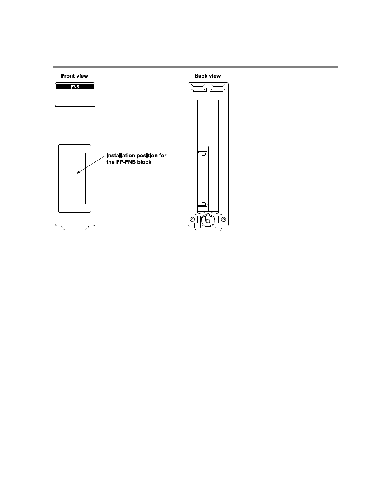
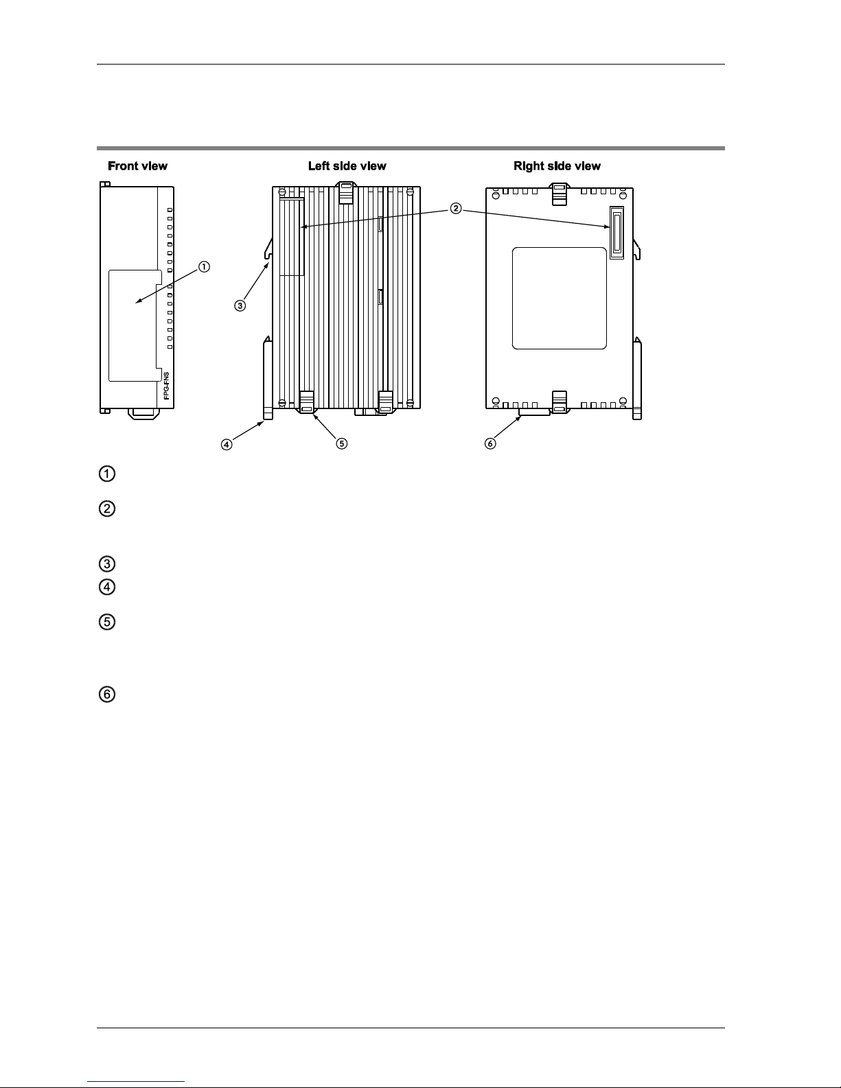
2.3 FPΣ FNS Unit
Installation position for FP-FNS block
FP expansion connector
Used to connect the unit to the control unit or other expansion units.
DIN standard rail attachment
DIN rail attachment lever
Expansion hook
Used to secure an expansion unit. The hook is also used for installation on the flat type
mounting plate (part no. AFP0804).
Function earth connector
At least one of the pins must be connected to function earth to achieve proper EMC behavior.
The FP-FNS unit is connected to the left side of the control unit via the FP expansion
connector.
FP-FNS Blocks
15
2.4 FP-FNS Blocks
Various FP-FNS blocks are available to meet your networking needs.
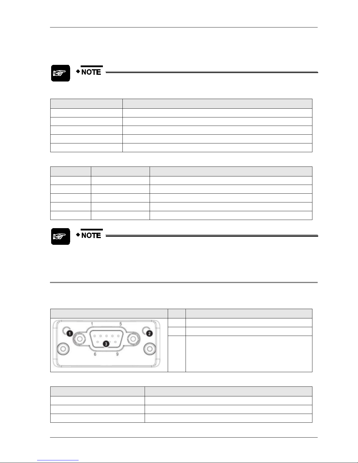
2.4.1 FP-FNS Block PROFIBUS DP
This FP-FNS block connects the unit to a PROFIBUS network.
Front view
No.
Item
1
Operation mode
2
Status
3
PROFIBUS connector (DB9F)
Operation Mode
State
Indication
Comments
Off
Not online/No power
-
Green
Online, data exchange
-
Flashing green
Online, clear
-
Flashing red (1 flash)
Parametrization error
-
Flashing red (2 flashes)
PROFIBUS configuration error
Slave configuration does not
match master configuration
Status
State
Indication
Comments
Off
No power or not initialized
FP-FNS state = 'SETUP¨' or 'NW_INIT'
Green
Initialized
FP-FNS has left the 'NW_INIT' state
Flashing green
Initialized, diagnostic event(s) present
Extended diagnostic bit is set
Red
Exception error
FP-FNS state = 'EXCEPTION'
Parts and Functions
16
PROFIBUS connector, DB9F, 9-pin Sub-D female
Pin
Signal
Description
1
-
- 2 -
- 3 B Line
Positive RxD/TxD, RS485 level
4
RTS
Request to send
5
GND
Bus ground (isolated)
6
+5V bus output (see note)
+5V termination power (isolated)
7
-
- 8 A Line
Negative RxD/TxD, RS485 level
9
-
-
Housing
Cable shield
FP: Internally connected to the function earth connector of the
FNS unit.
FP2: Internally connected to the earth terminal of the power unit.
Any current drawn from pin 6, the +5V bus output pin, will affect the total power
consumption.
2.4.2 FP-FNS Block DeviceNet
This FP-FNS block connects the unit to a DeviceNet network.
Front view
No.
Item
1
Network status LED
2
Module status LED
3
DeviceNet connector
Network Status
During start-up, an LED test is performed according to the DeviceNet standard.
State
Indication
Off
Not online/No power
Green
Online, one or more connections are established
Flashing green (1Hz)
Online, no connections established
Red
Critical link failure
Flashing red (1Hz)
One or more connections timed out
FP-FNS Blocks
17
Module Status
During start-up, an LED test is performed according to the DeviceNet standard.
State
Indication
Off
No power or not initialized
Green
Operating in normal condition
Flashing green (1Hz)
Missing or incomplete configuration, device needs to be configured
Red
Unrecoverable fault(s)
Flashing red (1Hz)
Recoverable fault(s)
DeviceNet Connector
Pin
Signal
Description
1
V-
Negative bus supply voltage (see note)
2
CAN_L
CAN low bus line
3
SHIELD
Cable shield
4
CAN_H
CAN high bus line
5
V+
Positive bus supply voltage (see note)
Mandatory 24V bus power.
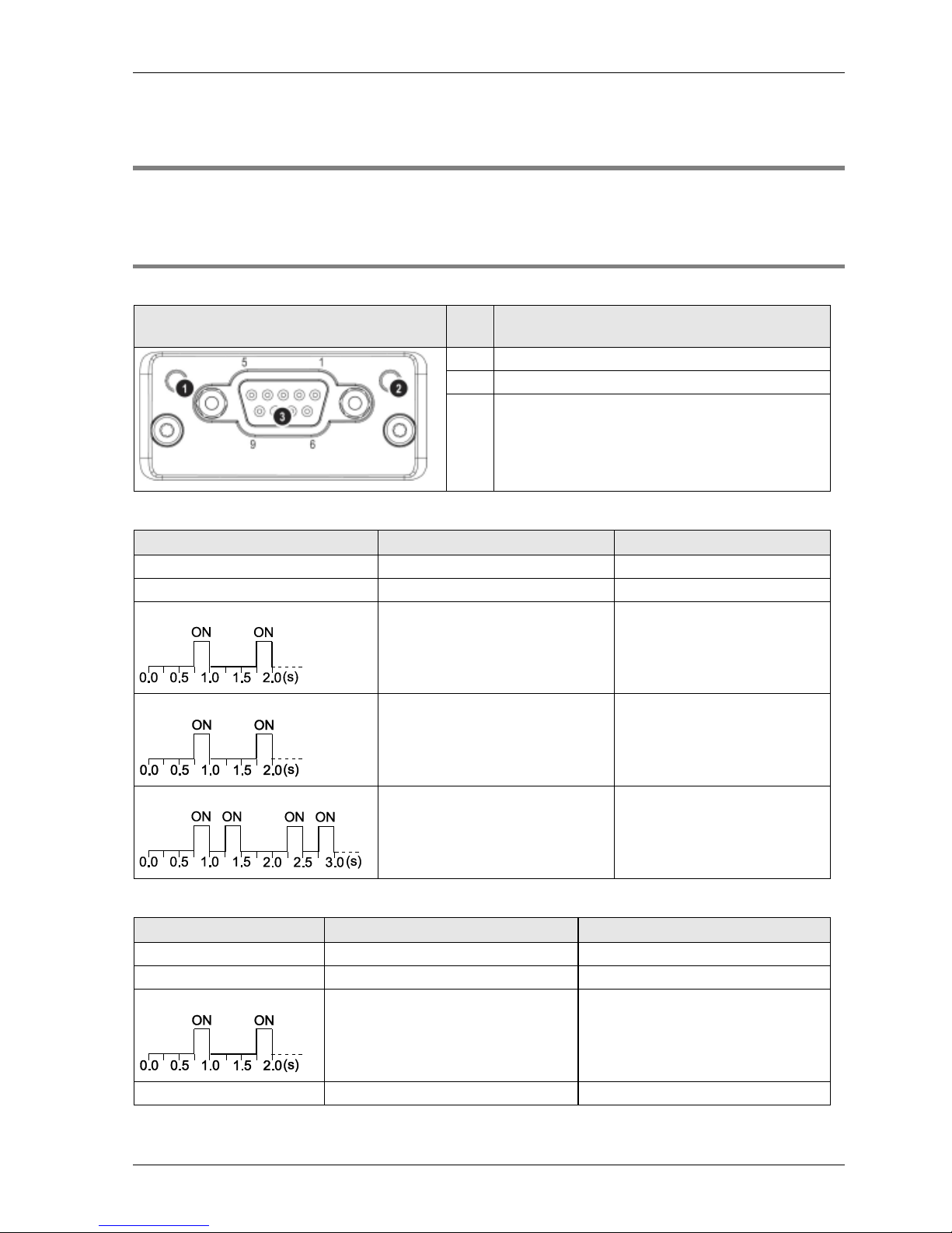
2.4.3 FP-FNS Block CANopen
This FP-FNS block connects the unit to a CANopen network.
AFPN-AB6218
Front view
No.
Item
1
RUN LED
2
ERROR LED
3
CANopen interface
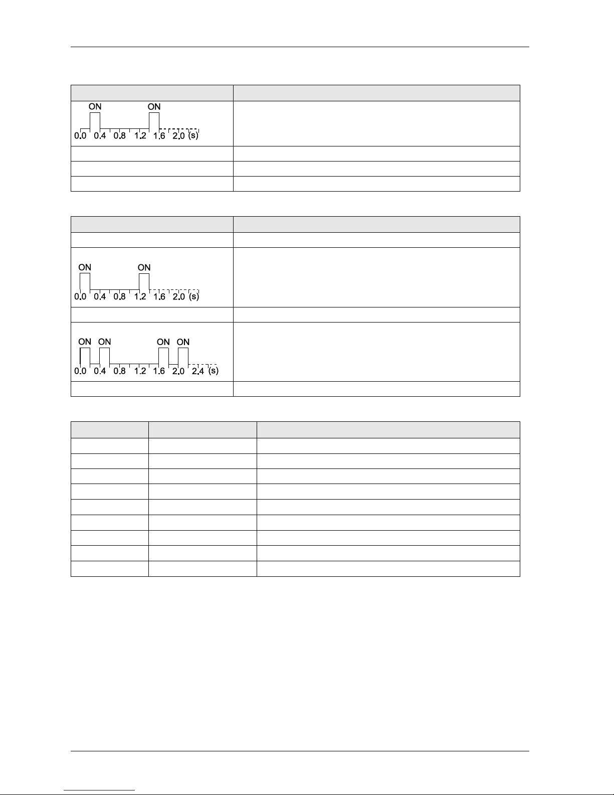
RUN
State
Indication
Off
No power or device is in "Exception" state
Flickering green (10Hz)
Automatic baud rate detection
Single flash green
Device stopped
Parts and Functions
18
State
Indication
Blinking green (2.5Hz)
Device is in "pre-operational" state
Green
"Operational" state
Red
Fatal event encountered. Bus interface is in physically passive state.
ERROR
State
Indication
Off
No power or device is in working condition
Single flash red
A bus error counter has reached warning limit
Flickering red (10Hz)
LSS (Layer Setting Service) in progress
Double flash red
Error control event has occurred
Red
Bus off or fatal event
CANopen Interface for AFPN-AB6218
Pin
Signal
Description
1
2
CAN_L
CAN low bus line (dominant low)
3
CAN_GND
Negative bus power supply input
4
5
6
7
CAN_H
CAN high bus line (dominant high)
8
9
FP-FNS Blocks
19
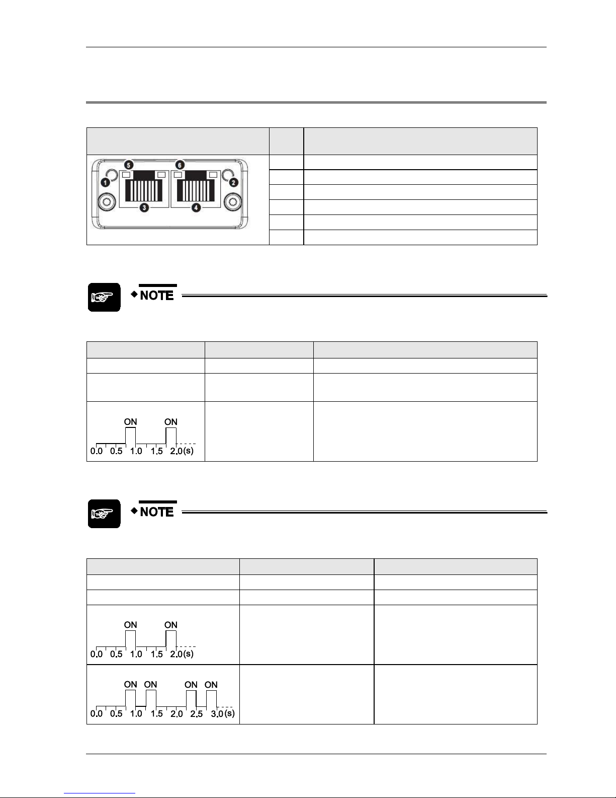
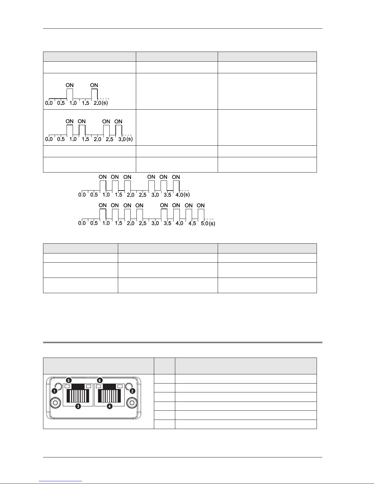
2.4.4 FP-FNS Block PROFINET IO
This FP-FNS block connects the unit to a PROFINET IO network.
Front view
No.
Item
1
Network status LED
2
Module status LED
3
Ethernet port 1
4
Ethernet port 2
5
Link/Activity LED (port 1)
6
Link/Activity LED (port 2)
Network Status
During start-up, a test sequence is performed on this LED.
State
Indication
Comments
Off
Offline
No power, or no connection with the IO controller
Green
Online (RUN)
Connection with IO controller established
IO controller in RUN state
Green, flashing
Online (STOP)
Connection with IO controller established
IO controller in STOP state
Module Status
During start-up, a test sequence is performed on this LED.
State
Indication
Comments
Off
No power or not initialized
FP-FNS state = 'SETUP¨' or 'NW_INIT'
Green
Normal operation
FP-FNS has left the 'NW_INIT' state
Green, 1 flash
Diagnostic event(s)
Diagnostic event(s) present
Green, 2 flashes
Blink
Used by engineering tools to identify the
node on the network.
Parts and Functions
20
State
Indication
Comments
Red
Exception error
FP-FNS state = 'EXCEPTION'
Red, 1 flash
Configuration Error
Expected configuration by controller
differs from real configuration.
Red, 2 flashes
IP Address Error
IP address not set
Red, 3 flashes*
Station Name Error
Station Name not set
Red, 4 flashes*
Internal Error
FP-FNS has encountered a major
internal error.
*3 flashes:
*4 flashes:
LINK/Activity LED
LED State
Indication
Comments
Off
No Link
No link, no communication present
Green
Link
Ethernet link established, no
communication present
Green, flickering (10Hz)
Activity
Ethernet link established,
communication present
Ethernet interface, RJ45
The Ethernet interface operates at 100Mbit, full duplex, as required by PROFINET.
2.4.5 FP-FNS Block BACnetIP
This FP-FNS block connects the unit to a BACnetIP network.
Front view
No.
Item
1
Network status LED
2
Module status LED
3
Ethernet port 1
4
Ethernet port 2
5
Link/Activity LED (port 1)
6
Link/Activity LED (port 2)

FP-FNS Blocks
21
Network Status
During start-up, a test sequence is performed on this LED.
State
Indication
Comments
Off
Offline
No power, or no IP address
Green
Online (RUN)
On-line, one or more BACnet messages have arrived
Module has active COV subscriptions
At least one value object has one or more events
enabled
Green,flashing
Online, waiting
Waiting for first BACnet message
Red
Duplicate IP address
FATAL error
Red, flashing
Connection timeout
No BACnet message has been received within the
configured 'process active timeout’ time.
A COV or Alarm/Event notification could not be sent
to its recipient.
Module Status
During start-up, a test sequence is performed on this LED.
State
Indication
Comments
Off
No power
FP-FNS state = 'SETUP¨' or 'NW_INIT'
Green
Normal operation
FP-FNS has left the 'NW_INIT' state
Red/green, alternating
Firmware update from file
system in progress
Red
Major fault
EXCEPTION-state, FATAL error etc.
Red, flashing
Recoverable fault(s)
LINK/Activity LED
LED State
Indication
Comments
Off
No Link
No link, no communication present
Green
Link (100 Mbit/s) established
Ethernet link established, no
communication present
Green, flickering (10Hz)
Activity (100 Mbit/s)
Ethernet link established,
communication present
Yellow
Link (10 Mbit/s) established
Ethernet link established, no
communication present
Yellow, flickering (10Hz)
Activity (10 Mbit/s)
Ethernet link established,
communication present
Parts and Functions
22
Ethernet interface, RJ45
The Ethernet interface supports autonegotiation and Auto MDI-X, with 10/100Mbit, full or half
duplex operation.
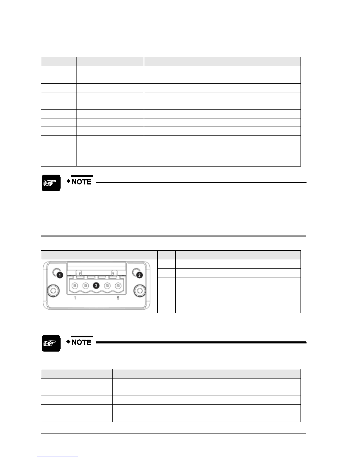
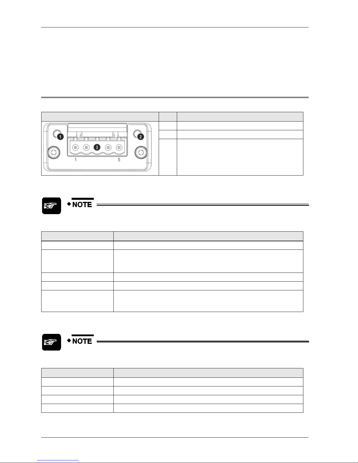
2.4.6 FP-FNS Block BACnet MS/TP
This FP-FNS block connects the unit to a BACnetMS/TP network.
Front view
No.
Item
1
Network status LED
2
Module status LED
3
BACnet MS/TP connector
Network Status
During start-up, a test sequence is performed on this LED.
State
Indication
Off
No power
Green
On-line, one or more BACnet messages have arrived
Module has active COV subscriptions
At least one value object has one or more events enabled
Flashing green (1Hz)
On-line, waiting for first BACnet message
Red
FATAL error
Flashing red (1Hz)
Connection timeout. No BACnet message has been received within the configured
‘process active timeout’ time.
A COV or Alarm/Event notification could not be sent to its recipient
Module Status
During start-up, a test sequence is performed on this LED.
State
Indication
Off
No power
Green
Operating in normal condition
Red
Major fault (EXCEPTION-state, FATAL error etc.)
Flashing red (1Hz)
Recoverable fault(s)

FP-FNS Blocks
23
BACnet MS/TP Connector
Pin
Signal
Description
1
Common
Signal common
2
Data-
Negative RS485 RxD/TxD
3
Shield
Cable shield
4
Data+
Positive RS485 RxD/TxD
5
(Not used)
(Not used)


Chapter 3
Specifications

Specifications
26
3.1 FNS Unit General Specifications
Item
Description
Operating temperature
0 to +55°C/32 to +131°F
Storage temperature
-20 to +70°C/-4 to +158°F
Operating humidity
30 to 85% RH (non-condensing)
Storage humidity
30 to 85% RH (non-condensing)
Vibration resistance
10 to 55Hz, 1 cycle/min: double amplitude of 0.75mm/0.030in., 10 min. on 3 axes
Shock resistance
Shock of 98m/s2 or more, 4 times on 3 axes
Operation condition
Free from corrosive gases and excessive dust
Current consumption
55mA or less at 5V
Weight (main unit)
FP2-FNS: 88g
FP-FNS: 61g

FP-FNS Block General Specifications
27
3.2 FP-FNS Block General Specifications
3.2.1 FP-FNS Block PROFIBUS DP General Specifications
Item
Description
Operating temperature
0 to +55°C/32 to +131°F
Storage temperature
-20 to +70°C/-4 to +158°F
Operating humidity
30 to 85% RH (non-condensing)
Storage humidity
30 to 85% RH (non-condensing)
Vibration resistance
10 to 55Hz, 1 cycle/min: double amplitude of 0.75mm/0.030in., 10 min. on 3 axes
Shock resistance
Shock of 98m/s2 or more, 4 times on 3 axes
Immunity
EN61000-4-2, EN61000-4-3, EN61000-4-4, EN61000-4-5, EN61000-4-6
Operation condition
Free from corrosive gases and excessive dust
Insulation resistance
Min. 100M (measured with a 500V DC megger)
Breakdown voltage
500V AC, 1 min. between DC external terminal and ground terminal
Current consumption
230mA or less at 5V
Weight
31g
3.2.2 FP-FNS Block DeviceNet General Specifications
Item
Description
Operating temperature
0 to +55°C/32 to +131°F
Storage temperature
-20 to +70°C/-4 to +158°F
Operating humidity
30 to 85% RH (non-condensing)
Storage humidity
30 to 85% RH (non-condensing)
Vibration resistance
10 to 55 Hz, 1 cycle/min: double amplitude of 0.75mm/0.030in., 10 min. on 3 axes
Shock resistance
Shock of 98m/s2 or more, 4 times on 3 axes
Immunity
EN61000-4-2, EN61000-4-3, EN61000-4-4, EN61000-4-5, EN61000-4-6
Operation condition
Free from corrosive gases and excessive dust
Insulation resistance
Min. 100M (measured with a 500 V DC megger)
Breakdown voltage
500V AC, 1 min. between DC external terminal and ground terminal
Current consumption
65mA or less at 5V; additional 140mA for bus power at 24V
Weight
32g

Specifications
28
3.2.3 FP-FNS Block CANopen General Specifications
Item
Description
Operating temperature
0 to +55°C/32 to +131°F
Storage temperature
-20 to +70°C/-4 to +158°F
Operating humidity
30 to 85% RH (non-condensing)
Storage humidity
30 to 85% RH (non-condensing)
Vibration resistance
10 to 55Hz, 1 cycle/min: double amplitude of 0.75mm/0.030in., 10 min. on 3 axes
Shock resistance
Shock of 98m/s2 or more, 4 times on 3 axes
Immunity
EN61000-4-2, EN61000-4-3, EN61000-4-4, EN61000-4-5, EN61000-4-6
Operation condition
Free from corrosive gases and excessive dust
Insulation resistance
Min. 100M (measured with a 500V DC megger)
Breakdown voltage
500V AC, 1 min. between DC external terminal and ground terminal
Current consumption
65mA or less at 5V; additional 140mA for bus power at 24V
Weight
32g
3.2.4 FP-FNS Block PROFINET IO General Specifications
Item
Description
Operating temperature
0 to +55°C/32 to +131°F
Storage temperature
-20 to +70°C/-4 to +158°F
Operating humidity
30 to 85% RH (non-condensing)
Storage humidity
30 to 85% RH (non-condensing)
Vibration resistance
10 to 55Hz, 1 cycle/min: double amplitude of 0.75mm/0.030in., 10 min. on 3 axes
Shock resistance
Shock of 98m/s2 or more, 4 times on 3 axes
Immunity
EN61000-4-2, EN61000-4-3, EN61000-4-4, EN61000-4-5, EN61000-4-6
Operation condition
Free from corrosive gases and excessive dust
Insulation resistance
Min. 100M (measured with a 500V DC megger)
Breakdown voltage
500V AC, 1 min. between DC external terminal and ground terminal
Current consumption
375mA or less at 5V
Weight
31g
3.2.5 FP-FNS Block BACnet/IP General Specifications
Item
Description
Operating temperature
0 to +55°C/32 to +131°F
Storage temperature
-20 to +70°C/-4 to +158°F
Operating humidity
30 to 85% RH (non-condensing)
Storage humidity
30 to 85% RH (non-condensing)
Vibration resistance
10 to 55Hz, 1 cycle/min: double amplitude of 0.75mm/0.030in., 10 min. on 3 axes
 Loading...