

Panasonic FP-M Hardware Manual

PROGRAMMABLE CONTROLLER
FP-M
Hardware
FP-M Hardware
ACG-M0045-1 94.12

Safety Precautions
Observe the following notices to ensure personal safety or to prevent accidents.
To ensure that you use this product correctly, read this User’s Manual thoroughly before use.
Make sure that you fully understand the product and information on safe.
This manual uses two safety flags to indicate different levels of danger.
WARNING
If critical situations that could lead to user’s death or serious injury is assumed by mishandling of the
product.
-Always take precautions to ensure the overall safety of your system, so that the whole
system remains safe in the event of failure of this product or other external factor.
-Do not use this product in areas with inflammable gas. It could lead to an explosion.
-Exposing this product to excessive heat or open flames could cause damage to the lithium
battery or other electronic parts.
CAUTION
If critical situations that could lead to user’s injury or only property damage is assumed by mishandling
of the product.
-To prevent abnormal exothermic heat or smoke generation, use this product at the values le ss
than the maximum of the characteristics and performance that are assure in these specifications.
-Do not dismantle or remodel the product. It could lead to abnormal exothermic heat or
smoke generation.
-Do not touch the terminal while turning on electricity. It could lead to an electric shock..
-Use the external devices to function the emergency stop and interlock circuit.
-Connect the wires or connectors securely.
The loose connection might cause abnormal exothermic heat or smoke generation
-Do not allow foreign matters such as liquid, flammable materials, metals to go into the
inside of the product. It might cause exothermic heat or smoke generation.
-Do not undertake construction (such as connection and discon nection) while the power
supply is on.
Copyright / Trademarks
-This manual and its contents are co pylighted.
-You may not copy this manual,in whole or part,without written consent of Matsushita Electric
Works,Ltd.
-Windows and Windows NT are registered trademarks of Microsoft Corporation in the
United States and/or other countries.
-All other company names and product names are trademarks or registered
trademarks of their respective owners.
-Matsushita Electric Wo rks,Ltd. pursues a policy of continuous improvement of the
Design and performance of its products, therefore,we reserve the right to change the manual/
product without notice.

CONTENTS
CHAPTER 1: FEATURES
1-1. Features and Functions...........................................................................................2
1. Features..............................................................................................................2
2. Functions............................................................................................................3
1) Advanced control functions.......................................................................3
2) Network .....................................................................................................6
1-2. Product Types.........................................................................................................9
1. Control Boards...................................................................................................9
2. Expansion Boards............................................................................................10
3. Intelligent Boards.............................................................................................10
4. Link Boards and Adapters ...............................................................................11
1-3. Expansion and Configurations .............................................................................12
1. Expansion of FP-Ms ........................................................................................12
2. Restriction of Expansion..................................................................................12
1) Expansion boards.....................................................................................12
2) Intelligent boards .....................................................................................12
3) Link boards..............................................................................................12
3. Combination of Boards....................................................................................13
1) Combination of relay output type control and expansion boards............13
2) Combination of transistor output type control and expansion boards.....13
1-4. Programming Tools for FP-Ms ............................................................................14
1. Programming Tools .........................................................................................14
1) NPST-GR Software .................................................................................14
2) FP Programmer II.....................................................................................14
2. Tools for Making a Programmed ROM...........................................................15
1) Writing a program to memory (EPROM) with an FP ROM writer.........15
2) Writing a program to memory (EPROM) with NPST-GR Software
and a commercially available ROM programmer....................................15
3) Writing a program to the memory (EPROM) via the master memory
(EEPROM) with a commercially available ROM programmer ..............16
CHAPTER 2: SPECIFICATIONS AND PARTS TERMINOLOGY
2-1. Specifications of Control Board and Expansion Board .......................................18
1. General.............................................................................................................18
2. Performance.....................................................................................................18
3. Input.................................................................................................................20
4. Output ..............................................................................................................20
1) Relay output type.....................................................................................20
2) Transistor output type (PNP and NPN open collector)............................21
2-2. Parts Terminology................................................................................................22
1. Control Boards.................................................................................................22
1) C20R and C20RC types...........................................................................22
2) C20T and C20TC types ...........................................................................24
3) C32T and C32TC types ...........................................................................26
2. Expansion Boards............................................................................................28
1) E20R type ................................................................................................28
CONTENTS

2) M1T-E type..............................................................................................29
3) M1T-EI type ............................................................................................30
4) M1T-EO type...........................................................................................31
3. Board and Case Structure ................................................................................32
1) Board type................................................................................................32
2) Case type..................................................................................................32
2-3. Dimensions...........................................................................................................33
1. Board Type ......................................................................................................33
1) Control boards..........................................................................................33
2) Expansion boards.....................................................................................33
3) Building dimensions................................................................................34
4) Mounting hole dimensions.......................................................................34
2. Case Type ........................................................................................................35
1) Case dimensions for control, expansion, intelligent and link boards ......35
2) Building dimensions................................................................................35
3) Mounting hole dimensions.......................................................................35
CHAPTER 3: I/O ALLOCATION
3-1. I/O Allocation of Control Boards.........................................................................38
3-2. I/O Allocation of Expansion Boards....................................................................39
3-3. I/O Allocation Examples......................................................................................40
CHAPTER 4: INSTALLATION AND WIRING
4-1. Stacking the Boards..............................................................................................42
1. Board Type ......................................................................................................42
2. Case Type ........................................................................................................43
4-2. Installation............................................................................................................44
1. Panel Mount.....................................................................................................44
1) Board type mounting method (without mounting plate) .........................44
2) Case type mounting method (using mounting plate)...............................44
2. DIN Rail Mount...............................................................................................44
3. Cautions...........................................................................................................45
4-3. Wiring...................................................................................................................46
1. Power Supply Wiring ......................................................................................46
1) Wiring for power supply..........................................................................46
2) Power supply lines...................................................................................46
3) Grounding................................................................................................47
4) Momentary power drop ...........................................................................47
5) Safety.......................................................................................................47
2. Input and Output Wiring (Control and Expansion Boards).............................48
1) Wiring for I/O power supply
(C20R control board and E20R expansion board)...................................48
2) Wiring description for I/O power supply
(C20R control board and E20R expansion board)...................................49
3) Wiring for I/O power supply
(C20T, C32T, M1T-E, M1T-EI, and M1T-EO series)............................50
4) Wiring description for I/O power supply
(C20T, C32T, M1T-E, M1T-EI, and M1T-EO series)............................51
5) Wiring for I/O connectors (MIL connector)............................................55
6) Wiring for I/O terminals..........................................................................61
7) Wiring for programming tool port...........................................................62
8) Wiring for RS232C port ..........................................................................62
CONTENTS

3. Wiring Diagram and Pin Layouts....................................................................63
1) Control boards..........................................................................................63
2) Expansion boards.....................................................................................68
CHAPTER 5: BEFORE PROGRAMMING
5-1. Operating Principles of the Programmable Controller.........................................74
1. Basic Configuration.........................................................................................74
2. Basic Operation ...............................................................................................76
5-2. Before Turning the Power ON .............................................................................78
1. Things to Check Before Turning the Power ON .............................................78
2. Operation Procedure........................................................................................79
5-3. How to Program the Programmable Controller ...................................................80
1. Making a Ladder Diagram...............................................................................80
2. Relays and Timer/Counter Contacts in the FP-M............................................81
3. I/O Allocation in the FP-M..............................................................................83
1) Control boards..........................................................................................83
2) Expansion boards.....................................................................................83
5-4. Programming with NPST-GR Software...............................................................84
1. System Configuration......................................................................................84
2. Features of NPST-GR Software Ver. 3 ...........................................................85
3. NPST-GR Configuration .................................................................................86
1) Overview of the programming screen .....................................................86
2) Overview of the menu window................................................................88
4. NPST-GR Installation and Configuration .......................................................89
1) Preparing for installation .........................................................................89
2) NPST-GR installation..............................................................................90
3) How to use NPST-GR effectively ...........................................................92
4) NPST-GR startup.....................................................................................92
5) Configuring NPST-GR............................................................................93
5. Exiting NPST-GR............................................................................................95
6. Basic Key Operation for Programs..................................................................96
7. Downloading a Program to the Programmable Controller..............................97
8. Saving a Program to Disk................................................................................98
9. Printing ............................................................................................................99
5-5. Programming with FP Programmer II................................................................100
1. System Configuration....................................................................................100
2. Downloading a Program to the Programmable Controller............................101
5-6. RAM and ROM Operations ...............................................................................103
1. RAM and ROM Operations...........................................................................103
2. Operation Without Backup Battery Enabled.................................................104
3. Notes on Operation with Memory (ROM Operation) ...................................105
5-7. How to Program ROM.......................................................................................106
1. Memory (ROM) Type....................................................................................106
2. Install the Memory (ROM)............................................................................107
3. How to Program ROM...................................................................................107
1) Writing a program to the memory (EPROM) via master memory
(EEPROM) with a commercially available ROM programmer ............107
2) Writing a program to the memory (EPROM) with NPST-GR
Software and a commercially available ROM programmer..................109
CHAPTER 6: TROUBLESHOOTING AND MAINTENANCE
6-1. Self-diagnostic Function ....................................................................................112
CONTENTS

1. Operation Monitor LEDs When an Error Occurs..........................................112
2. Operation Status When an Error Occurs........................................................113
1) Duplicated output error (total-check error)............................................113
2) Battery error (self-diagnostic error).......................................................113
3) Operation error (self-diagnostic error)...................................................113
6-2. Troubleshooting .................................................................................................114
1. Points to be Checked When an Error Occurs ................................................114
6-3. Error Codes ........................................................................................................123
1. Table of Total-check Error Codes .................................................................123
2. Table of Self-diagnostic Error Codes ............................................................124
6-4. Maintenance .......................................................................................................125
1. Replacement of Backup Battery....................................................................125
1) Battery life .............................................................................................125
2) Using backup battery type .....................................................................125
3) How to replace backup battery ..............................................................125
2. Check Items ...................................................................................................126
CHAPTER 7: INTELLIGENT AND LINK BOARDS
7-1. Analog I/O Board...............................................................................................128
1. Specifications.................................................................................................128
1) General...................................................................................................128
2) Performance...........................................................................................128
3) Restriction of expansion ........................................................................129
2. Dimensions ....................................................................................................129
3. Parts Terminology .........................................................................................130
4. Wiring............................................................................................................132
7-2. A/D Converter Board .........................................................................................133
1. Specifications.................................................................................................133
1) General...................................................................................................133
2) Performance...........................................................................................133
3) Restriction of expansion ........................................................................134
2. Dimensions ....................................................................................................134
3. Parts Terminology .........................................................................................135
4. Wiring............................................................................................................137
7-3. D/A Converter Board .........................................................................................138
1. Specifications.................................................................................................138
1) General...................................................................................................138
2) Performance...........................................................................................138
3) Restriction of expansion ........................................................................139
2. Dimensions ....................................................................................................139
3. Parts Terminology .........................................................................................140
4. Wiring............................................................................................................142
7-4. Programming for Analog I/O, A/D Converter, and D/A Converter Boards ......143
1. Digital Values of Analog Input......................................................................143
2. Digital Values of Analog Output...................................................................144
3. Specification of Analog I/O Data ..................................................................146
4. Applications...................................................................................................147
7-5. High-speed Counter Board.................................................................................148
1. Specifications.................................................................................................148
1) General...................................................................................................148
2) Performance...........................................................................................148
3) Differences in specifications between high-speed counter function
with FP-M control board and high-speed counter board.......................149
4) Restriction of expansion ........................................................................150
CONTENTS

2. Dimensions ....................................................................................................150
3. Parts Terminology .........................................................................................151
4. I/O Allocation................................................................................................153
5. Wiring............................................................................................................156
6. Programming for High-speed Counter Board................................................157
1) High-speed counter board related instructions F0 (MV), F1 (DMV)....157
2) Notes on programming the high-speed counter.....................................158
3) Applications...........................................................................................159
7-6. FP-M Transmitter Master Board (MEWNET-TR) ............................................161
1. Specifications.................................................................................................162
1) General...................................................................................................162
2) Performance...........................................................................................162
3) Restriction of expansion ........................................................................162
2. Dimensions ....................................................................................................162
3. Parts Terminology .........................................................................................163
7-7. FP-M I/O Link Board (MEWNET-F)................................................................165
1. Specifications.................................................................................................166
1) General...................................................................................................166
2) Performance...........................................................................................166
3) Restriction of expansion ........................................................................166
2. Dimensions ....................................................................................................166
3. Parts Terminology .........................................................................................167
CHAPTER 8: APPENDIX
8-1. Performance Specifications................................................................................170
1. Control and Expansion Board Specifications................................................170
2. Intelligent Boards Specifications...................................................................173
1) Analog I/O board specifications............................................................173
2) A/D converter and D/A converter board specifications.........................174
3) High-speed counter board specifications...............................................175
4) FP-M transmitter master board (MEWNET-TR) specifications ...........176
5) FP-M I/O link board (MEWNET-F) specifications...............................176
8-2. Dimensions.........................................................................................................177
1. Board Type ....................................................................................................177
1) Control boards........................................................................................177
2) Expansion boards...................................................................................177
3) Intelligent and link boards .....................................................................178
4) Building dimensions..............................................................................179
5) Mounting hole dimensions.....................................................................179
2. Case Type ......................................................................................................180
1) Case dimensions for control, expansion, intelligent and link boards ....180
2) Building dimensions..............................................................................180
3) Mounting hole dimensions.....................................................................180
8-3. I/O Allocation Table...........................................................................................181
1. I/O Allocation of Control Boards ..................................................................181
2. I/O Allocation of Expansion Boards..............................................................181
3. Allocation of Analog I/O, A/D Converter, and D/A Converter Boards........182
4. Allocation of High-speed Counter Board......................................................183
5. I/O Allocation of FP-M Transmitter Master Board.......................................184
6. I/O Allocation of FP-M I/O Link Board........................................................184
8-4. Table of Memory Areas .....................................................................................185
8-5. System Registers ................................................................................................187
1. What Are System Registers...........................................................................187
2. Table of the System Registers .......................................................................189
CONTENTS

8-6. Special Internal Relays.......................................................................................198
8-7. Special Data Registers........................................................................................201
8-8. Table of the Error Codes....................................................................................210
1. Table of Total-check Error Codes .................................................................210
2. Table of Self-diagnostic Error Codes ............................................................211
8-9. Table of Instructions...........................................................................................212
1. Basic Instructions...........................................................................................212
2. High-level Instructions ..................................................................................215
8-10. Table of Binary/BCD Expressions.....................................................................219
8-11. Versions of Programming Tools ........................................................................220
1. Differences Between NPST-GR Ver. 2.4 and 3.1 .........................................220
2. Differences Between the FP Programmer and FP Programmer II.................222
8-12. Modem Communication.....................................................................................224
1. Using the Programming Tool Port (FP-M control board all types)...............224
2. Using the RS232C Port
[FP-M C type control boards (C20RC/C20TC/C32TC)] ..............................227
8-13. Terminology.......................................................................................................232
8-14. Product Types.....................................................................................................239
1. Case Type ......................................................................................................239
2. Board Type ....................................................................................................241
3. Programming Tools .......................................................................................244
4. Wiring Parts for I/O Terminal .......................................................................250
5. Wiring Parts for I/O Connectors (MIL connectors).......................................250
6. Accessories ....................................................................................................252
7. Maintenance Parts..........................................................................................253
INDEX..............................................................................................................................................................254
RECORD OF CHANGES........................................................................................................................258
CONTENTS

CHAPTER 1
FEATURES
1-1. Features and Functions............................................................2
1. Features...............................................................................2
2. Functions ............................................................................3
1-2. Product Types..........................................................................9
1. Control Boards....................................................................9
2. Expansion Boards.............................................................10
3. Intelligent Boards .............................................................10
4. Link Boards and Adapters................................................11
1-3. Expansion and Configurations ..............................................12
1. Expansion of FP-Ms.........................................................12
2. Restriction of Expansion ..................................................12
3. Combination of Boards.....................................................13
1-4. Programming Tools for FP-Ms..............................................14
1. Programming Tools ..........................................................14
2. Tools for Making a Programmed ROM............................15
2
1-1. Features and Functions
1-1. Features and Functions
1. Features
• Excellent performance in a compact body
Succeeding the advanced functions of the FP1 programmable controller, the FP-M is designed to fulfill machine
building requirements. The advantages of compact size, expandability, and time-tested dependability are
convincing reasons to consider the FP-M as an alternative to the control systems with which you are familiar.
• Greatly increased program memory and high execution speed
FP-M surpasses the competition with a basic instruction execution speed of 1.6 µs/step and an ample program
capacity of 2,720 and 5,000 steps. The board is driven by battery-backed RAM (EEPROM or EPROM program
back-up option is also available). Types with an additional RS232C port and clock/calender (C types) are
available to boost the range of applications possible.
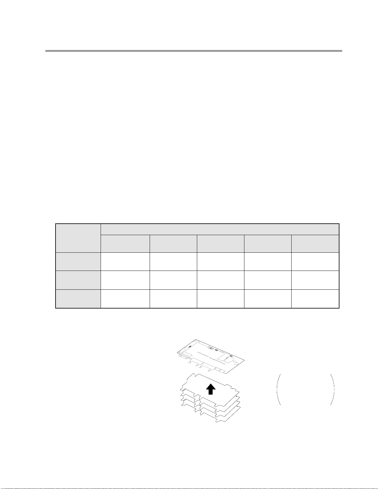
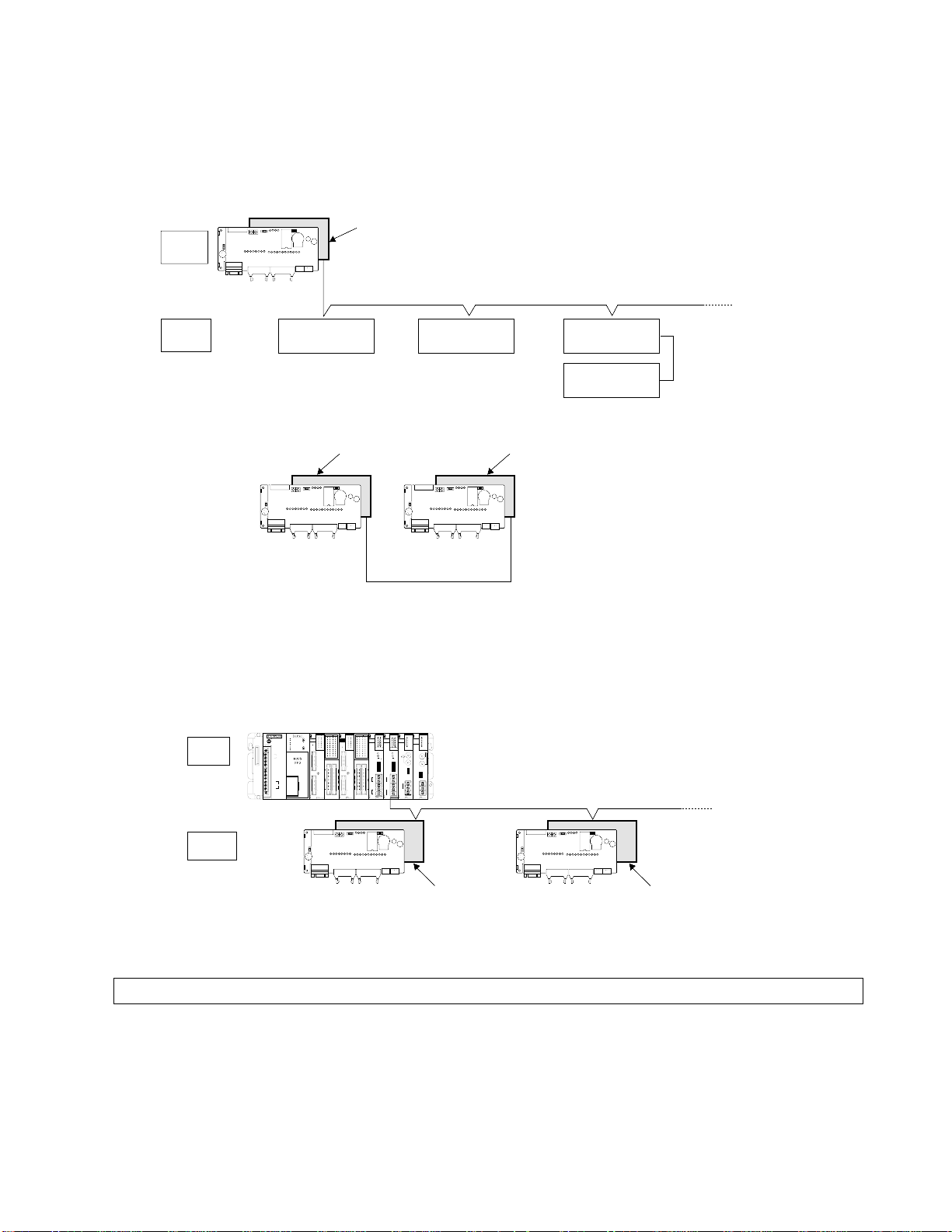
• Smart system expandability
Up to four expansion boards can be stacked under the control board, but no additional mounting space is needed.
This module enables you to add discrete I/O points and intelligent functions such as analog control, high-speed
counter control, and link functions easily.
Available expansion boards are:
Transistor I/O, Relay I/O, Analog I/O, A/D, D/A, High-speed Counter, I/O Link, and FP-M Transmitter Master
Boards.
I/O Expansion Example
For details about expansion refer to page 12.
* In the table above, the twenty I/O point relay type expansion board is used for the C20R and the forty I/O point
transistor type is used for the C20T and C32T.
• Easy programming environment
NPST-GR changes your personal computer into a powerful programming support tool. This editing software is
fully compatible with FP series programmable controllers.
Control board
Max.
4 boards
I/O points:
Total 192 points
Max. 256 points
using three transmitter
master boards
(MEWNET-TR)
refer to page 12
*C20R
(Relay output)
*C20T
(Transistor output)
*C32T
(Transistor output)
20
12 inputs/8 outputs
20
12 inputs/8 outputs
32
16 inputs/16 outputs
0 expansion
Control board
Total I/O points
40
24 inputs/16 outputs
60
36 inputs/24 outputs
72
40 inputs/32 outputs
1 expansion
60
36 inputs/24 outputs
100
60 inputs/40 outputs
112
64 inputs/48 outputs
2 expansions
80
48 inputs/32 outputs
140
84 inputs/56 outputs
152
88 inputs/64 outputs
3 expansions
100
60 inputs/40 outputs
180
108 inputs/72 outputs
192
112 inputs/80 outputs
4 expansions
3
1-1. Features and Functions
2. Functions
1) Advanced control functions
■ High-speed counter function
The built-in high-speed counter function supports four modes: two-phase input, UP, DOWN, and UP/DOWN.
The FP-M can read the input regardless of the scan time.
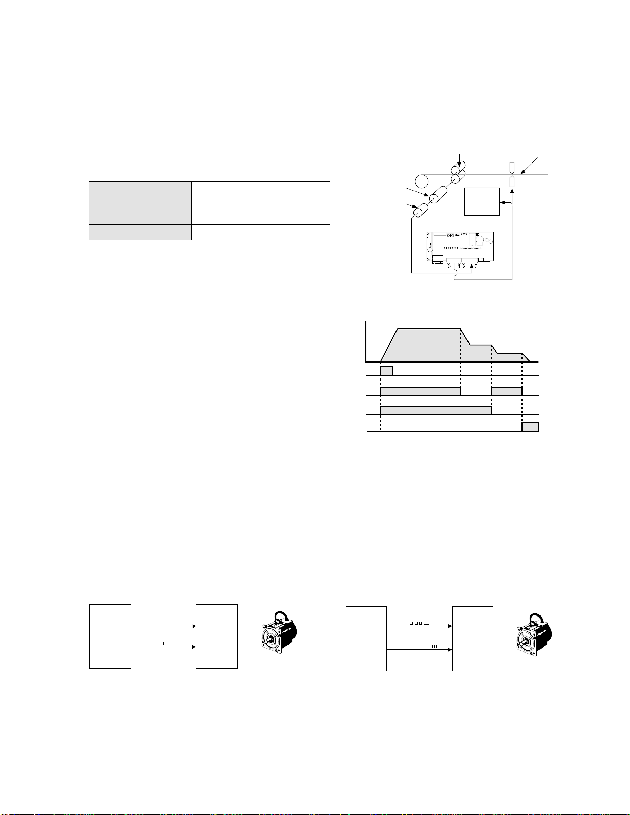
■ Pulse output function (transistor output type)
This function allows the output of a direct pulse (45 Hz to 4.9 k Hz) from the FP-M. In combination with a drive, a
motor can be controlled. As direct pulse is possible, an additional positioning controller is not necessary. As the
FP-M has two pulse outputs, it also supports motor drives with one input for forward driving and the other input for
reverse driving. To prevent incorrect forward/reverse driving, create an interlock circuit outside of the FP-M.
In addition, since the built-in high-speed counter can internally take the pulse output, no external wiring for feedback
control is required.
• Wiring example for a drive with one pulse input
and one direction input:
• Wiring example for a drive with two pulse inputs:
Pulse
Frequency
Start
signal
Y0
Y1
Speed
signal
Stop
signal
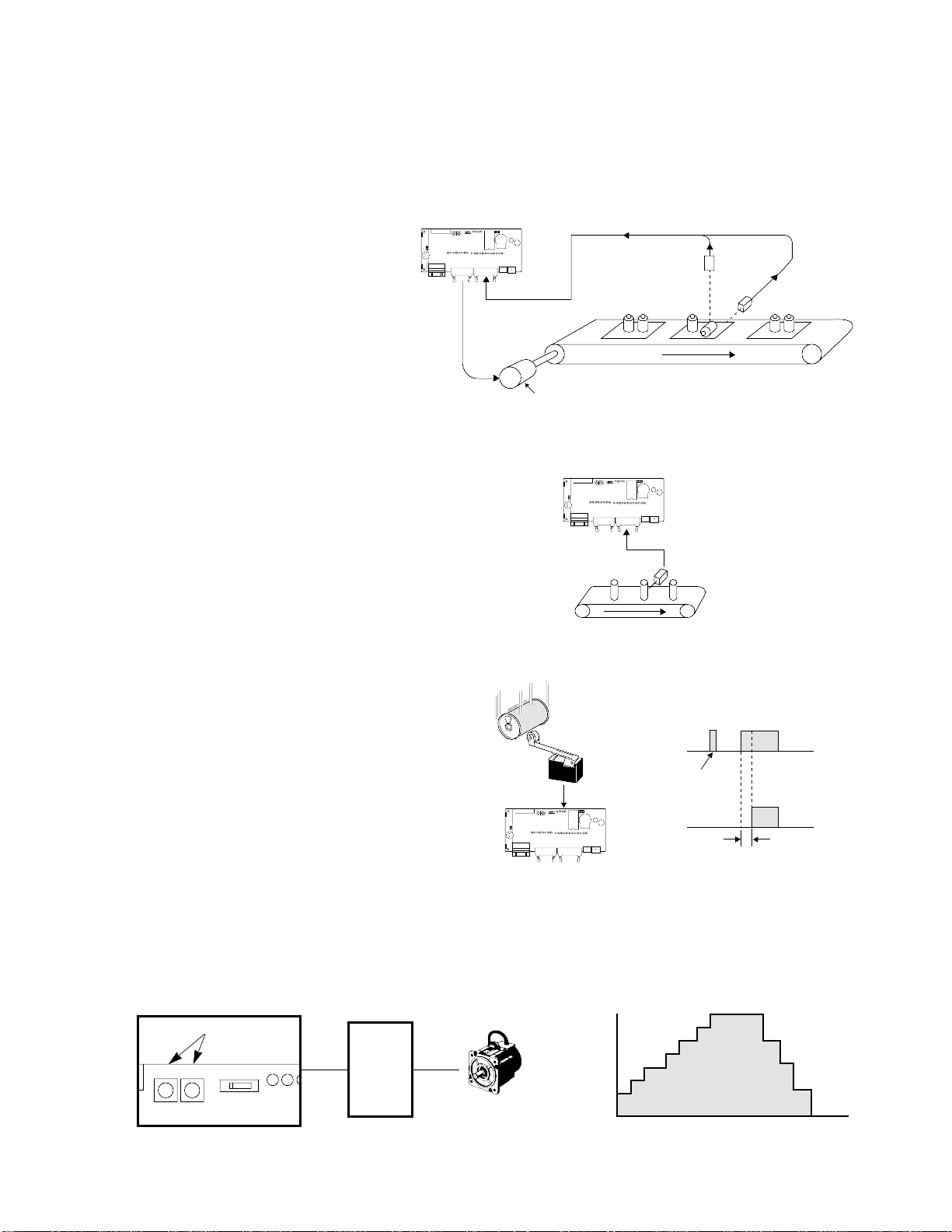
Application: Pattern output function
This function of the control board allows the setting
of a maximum of eight output patterns with 15 level
settings of the high-speed counter. Can also be
applied to multi-stage speed control with use of an
invertor.
Roller
Motor
Encoder
Cutter
Wire
Control
signal
Variable
motor
drive
FP-M control board
Max. counting speed
Counting range
1-phase: 10 k Hz
(when duty cycle ratio 50 %)
2-phase: 10 k Hz
–8,388,608 to 8,388,607
Y6
CW/CCW
Y7
Pulse
ON/OFF
FP-M
control
board
Motor
drive
Y7
Y6
CCW
FP-M
control
board
Motor
drive
CW
Motor Motor
4
1-1. Features and Functions
■Interrupt input function
This function executes an interrupt program immediately after an external interrupt input (minimum pulse width of
0.2 ms) occurs, regardless of the input timing. It enables high-speed processing at a fixed timing and is not affected
by scan time. Therefore it is useful when performing control which would be disrupted by variations in processing
time due to such factors as timing synchronization.
■ Pulse catch input function
■ Adjustable input time filtering function
■ Manual dial-set register control function
This function makes it possible to change the values of special data registers DT9040 and DT9041 within a range of
0 to 255 using the potentiometers on the control board. Input settings involving analog-type numerical data such as
analog timer and pulse output frequency changes can be performed.
Response time
Limit switch
FP-M
Limit
switch
Chattering noise
is ignored
FP-M
control
board
This function allows the input response
time (input time constant) of the control
board to be changed within a range of 1
to 128 ms in accordance with the input
device connected. This prevents input
errors due to such causes as limit switch
chattering noise.
Sensor
FP-M control board
This function catches input pulse signals
down to a minimum width of 0.5 ms. It is
effective for situations such as when the
sensor detects the moving target at a
high-speed.
Sensor 2
Sensor 1
Interrupt input
signal
Stop signal
Motor
FP-M control board
• Timing control on a board inspection line
Immediately executes interrupt program
when an edge detection signal comes in
by interrupt input from sensor 1. Sensor 2
inspects the part, and if an abnormality is
detected, the conveyor stops and the
abnormality is reported.
Pulse
Frequency
V0 V1
RUN
REMOTE PROG.
RUN PROG. E
(B
Motor
drive
Motor
FP-M control board
Potentiometers
(V0 and V1)

5
1-1. Features and Functions
■Forced ON/OFF control function
■Password protection function
This function forbids reading and writing of the program and system registers. It can be used for program protection
and when secrecy is required.
■Constant length scan setting function
The duration of one scan is fixed by setting it to units of 2.5 ms, eliminating variation in the scan time.
■Clock/Calendar control function (C20RC, C20TC, and C32TC types)
By means of year, month, day, hour, minute, second, and day of the week settings, this function makes it possible to
change temporal elements of control. It can be used for temporal control of such items as lighting, air conditioning,
and equipment.
This function allows the state of the input and output
contacts to be forced ON or OFF with a programming
tool (NPST-GR Software, etc.). By forcing the output
contact ON or OFF, the connection on the output side
can be checked. By forcing the input contact ON or
OFF, the program can be checked.
Personal
computer
ON
ON
FP-M control board
6
1-1. Features and Functions
2) Network
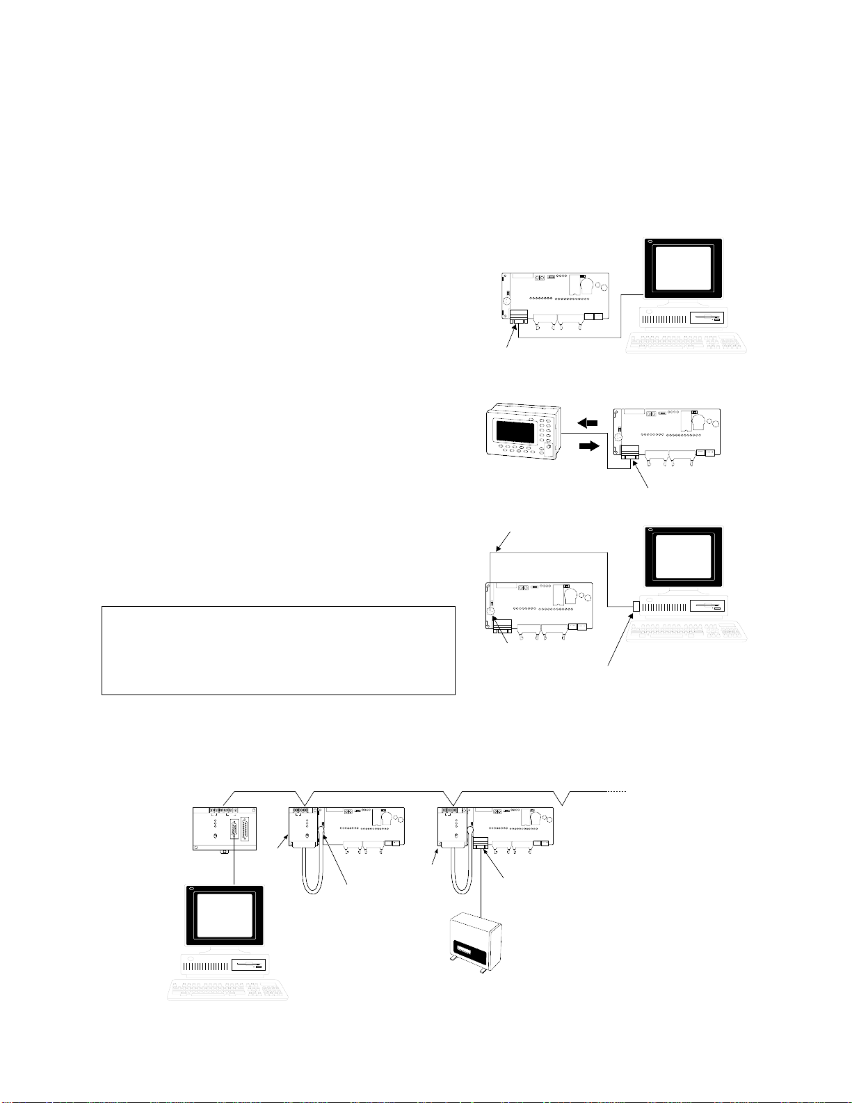
■Computer link function (MEWTOCOL)
This function allows the reading and writing of FP-M contact information and data register content from a host
computer. It can be used for such applications as data collection and the monitoring of operating conditions.
The computer program is written in BASIC and C languages.
Communication between one computer and one FP-M control board
• Using programming tool port (all series)
The programming tool port can also be used for direct
connection to a personal computer.
Note:
Communication between one computer and 32 FP-M control boards
Using a C-NET adapter, a maximum of 32 FP-M control boards can be connected with one personal computer. If a
bar code reader is connected via the RS232C port, this system can be used for the collection of various production
control information.
• Refer to C-NET LINK UNIT Technical Manual for details about computer link.
PC
C-NET
ADAPTER
ON
OFF
ON
ON
ABCDEF
ABCDEFGHI
AB ABCD
PC
C-NET
ADAPTER
ON
OFF
ON
ON
ABCDEF
ABCDEFGHI
AB
A
B
C
D
E
F
G
H
I
A
B
C
D
E
F
G
H
I
A
B
C
D
E
F
G
H
I
A
B
C
D
E
FG
H
I
A
B
Bar code reader
Personal
computer
C-NET
adapter
standard
type
C-NET
adapter
S2 type
A maximum of 32 FP-M
control boards can be connected.
PC
C-NET
ADAPTER
ON
OFF
ON
ON
ABCDEF
ABCDEFGHI
AB
C-NET
adapter
S2 type
Programming
tool port
RS232C port
FP-M control board FP-M control board
• When using a control board equipped with an
RS232C port (C20RC, C20TC, and C32TC types),
various combinations can be created by making a
computer link with the programming tool port and
connecting another device with the RS232C port.
When connected to an I.O.P. using the computer link
function, the I.O.P.’s data can be read as the FP-M’s
internal relay or data register. This can be used for such
operations as production control.
RS232C port
Personal computer
FP-M control board
• Using RS232C port (C20RC, C20TC, and C32TC types)
The RS232C port can be used for direct connection to a
personal computer.
Programming tool port
Personal computer
FP-M personal
computer cable
(for NPST-GR)
FP-M control board
RS232C interface adapter
a
b
c
d
I.O.P.
a
b
c
d
a
b
c
d
FP-M control board
RS232C port
7
1-1. Features and Functions
■MEWNET-TR (distributed I/O) system
I/O information can be exchanged between the master and several slave stations at a remote site. A maximum of 32
inputs and 32 outputs can be controlled per master board.
This system supports a total communication distance of 700 m per port using a twisted-pair cable. Master to master
communication is also available.
• Master-slave communication
• Master-master communication
■MEWNET-F (distributed I/O) system
Using a FP-M I/O link board, this function allows the exchange of I/O information with the master unit of the FP
series programmable controller through a two-conductor cable.
Note:
• Refer to “REMOTE I/O SYSTEM Technical Manual” for details about MEWNET-F (remote I/O) system.
Master
station
Transmitter master board
(MEWNET-TR)
FP-M control board
Slave
stations
FP I/O
transmitter unit
FP I/O
transmitter unit
FP I/O
transmitter unit
Max. 700 m with
twisted-pair cable
FP I/O
terminal unit
FP-M control board
Transmitter master board
(MEWNET-TR)
FP-M control board
Transmitter master board
(MEWNET-TR)
Max. 700 m with
twisted-pair cable
Master
station
FP3
RUN
POWER
PROG.
FUSE
TEST
BREAK
ERROR
BATT.
ALARM
L
100-240V AC
N
LINE GROUND
Matsushita
FRAME GROUND
Electric Works, Ltd.
COM
NO ALARM
RS422
NC
Master unit
IN64
IN32
OUT32
0
0
0
8
0
1
1
INITLAUZE
1
9
1
2
2
OUT32
IN32
2
A
2
3
3
TEST
3
B
3
4
4
4
C
5
5
4
12-24VDC
TRANSISTOR
0.1A5-24VDC
6
6
5
D
5
(NPN)
7
7
6
E
6
RUN
8
8
7
F
7
REMOTE
9
9
I. IVIII II.
I. IVIII II.
A
A
PROG.
B
B
C
C
D
D
E
E
F
F
10
10
I II III IV
1
1
20111
III.
III.
II I
II I
II III
IIIIV.
IIIIV.
10
10
11
10
10
I IV
1
20
1
1
IV III
IV III
II I
II I
OUT64
0
0
8
1
1
9
2
2
TRANSMITTER
A
3
3
MASTER
B
4
4
5
5
C
6
6
D
7
7
E
8
8
F
9
9
A
A
B
B
C
C
COMM.
D
D
E
E
F
F
ALARM.
I II III IV
DSP.SW.
MODE
SW.
20111
II III
+
10
I
10
11
-
I IV
F.G.
1
20
+
II
-
II I
II I
MEWNET LINK
MASTER
MASTER
C-NET
RECEIVE
POWER
8
0
9
TRANSMIT
1
TERMINATE
REMOTE
2
PC LINK
A
MEWNET
C-NET LINK
I/O
ALARM
3
LINK
B
MASTER
R/W
SD
WIRE TYPE
4
C
RD
5
D
RS485
ERROR1
ERROR
6
E
ERROR2
ALARM
7
F
SLAVE UNIT NO.
SLAVE UNIT NO.
UNIT NO.
COMM.
8
9
7
0
6
STATION
8
9
7
1
5
0
6
2
4
ALARM.
3
1
5
NO.
1-16
INPUT
2
4
3
DSP.SW.
17-32
OUTPUT
8
9
7
0
6
8
9
7
1
5
0
1
1
6
2
4
3
1
5
2
2
2
4
3
3
3
4
4
MODE
5
5
SW.
6
6
OFF
7
7
8
8
TERMINATE
MODE SW.
ON OFF
ON OFF
ON
1
2
3
4
+
ON
OFF
I
+
+
RS485
F.G.
-
-
+.
II
F.G.
F.G.
-.
Max. 700 m with
twisted pair cable
Slave
stations
FP-M control board
FP-M
I/O link board
FP-M control board
FP-M
I/O link board
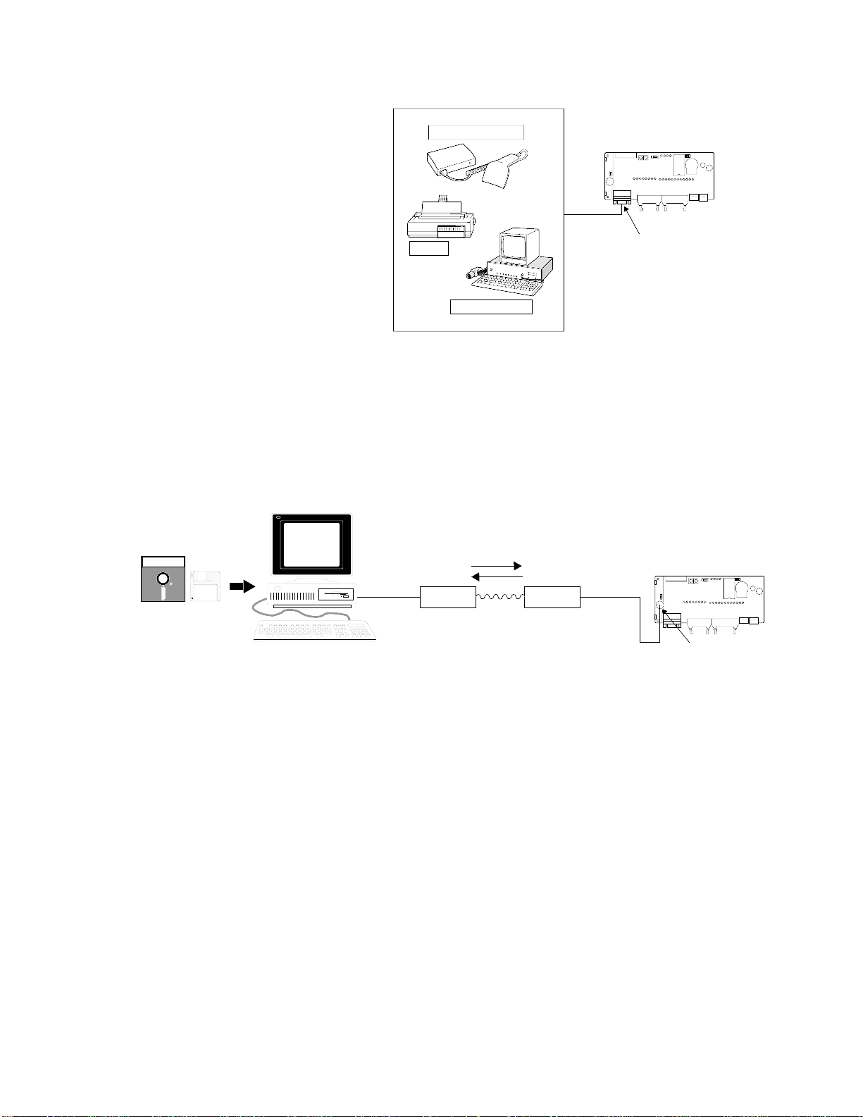
■General communication using RS232C port (C20RC, C20TC, and C32TC types)
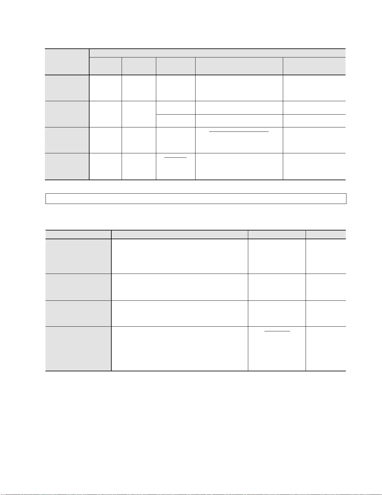
■Modem communication
Using a modem, the FP-M can perform long-distance communication with a personal computer to monitor and
change data and also to change the program. Using C-NET adapters, you can control up to 32 programmable
controllers from a personal computer. Through the RS232C port, the FP-M can initiate a call to a computer via
modems for alarm purposes.
Personal computer
NPST-GR Software
Modem Modem
Public telephone line
Programming
tool port
FP-M control board
RS232C port
National
abc
abc
ab
c
a
b
c
Bar code reader
Printer
Image checker
FP-M control board
This function allows data input and output
when connected to a device having an RS232C
port. Data reading from a bar code reader, data
output to a printer, and bilateral data exchange
with the image checker are all possible.
8
1-1. Features and Functions

9
1-2. Product Types
1-2. Product Types
1. Control Boards
Notes:
• * CPUs with a RS232C port and clock/calendar function (C20RC, C20TC and C32TC types).
• Board types include AFB88021 (4 spacers, 20 mm), APL9511 (power supply cable), AFB8505 (jumper
cable) and 4 screws (20 mm × 2, 8 mm × 2).
• Case types include the control board, case for control board (C20R type for AFC18011, C20T type for
AFC18012 and C32T type for AFC18013), AFB88032 (4 spacers, 8 mm), APL9511 (power supply cable),
AFB8505 (jumper cable), 4 screws (20 mm × 2, 8 mm × 2), and AFB6804 (mounting plate).
• 12 V DC operating voltage type is also available.
Series
Built-in
memory
C20R
C20T
C32T
Standard
type
C20RC
type*
Standard
type
C20TC
type*
Standard
type
C32TC
type*
Description
I/O point
RAM
(2.7 k steps)
RAM
(5 k steps)
RAM
(2.7 k steps)
RAM
(5 k steps)
RAM
(2.7 k steps)
RAM
(5 k steps)
20
Input: 12
Output: 8
20
Input: 12
Output: 8
20
Input: 12
Output: 8
20
Input: 12
Output: 8
32
Input: 16
Output: 16
32
Input: 16
Output: 16
Operating
voltage
24 V DC
24 V DC
24 V DC
24 V DC
24 V DC
24 V DC
Input type Output type
Sink/source
Sink/source
Source
Sink
Source
Sink
Source
Sink
Source
Sink
Relay, 2A 250 V AC
Relay, 2A 250 V AC
Transistor, 0.8 A
(NPN open collector)
Transistor, 0.8 A
(PNP open collector)
Transistor, 0.8 A
(NPN open collector)
Transistor, 0.8 A
(PNP open collector)
Transistor, 0.8 A
(NPN open collector)
Transistor, 0.8 A
(PNP open collector)
Transistor, 0.8 A
(NPN open collector)
Transistor, 0.8 A
(PNP open collector)
Part number
Board: AFC12212
Case: AFC10212
Board: AFC22212C
Case: AFC20212C
Board: AFC12242
Case: AFC10242
Board: AFC12252
Case: AFC10252
Board: AFC22242C
Case: AFC20242C
Board: AFC22252C
Case: AFC20252C
Board: AFC12342
Case: AFC10342
Board: AFC12352
Case: AFC10352
Board: AFC22342C
Case: AFC20342C
Board: AFC22352C
Case: AFC20352C
10
1-2. Product Types
2. Expansion Boards
Note:
3. Intelligent Boards
Type
Analog I/O board
A/D converter board
D/A converter board
High-speed counter
board
Description
Input: 4 channels/board
Output: 1 channel/board
Input/output range: 0 to 5 V, 0 to 10 V, 0 to 20 mA
Resolution: 1/256 (8 bits)
Input: 4 channels/board
Analog input range: 0 to 5 V, 0 to 10 V, 0 to 20 mA
Digital output range: K0 to K999
Output: 2 channels/board
Analog output range: 0 to 5 V, 0 to 10 V, 0 to 20 mA
Digital input range: K0 to K999
Input: 2 channels
Counting range: -8,388,608 to 8,388,607
Max. counting speed:
1-phase mode: 20 k Hz
2-phase mode: 5 k Hz
Operating voltage
24 V DC
24 V DC
24 V DC
Part number
AFB6480
AFB6400
AFB6410
AFB6420
• Operating voltage 12 V DC type is also available.
Series Description
I/O point
E20R
expansion
I/O board
M1T-E
expansion
I/O board
M1T-EI
expansion
input board
M1T-EO
expansion
output board
20
Input: 12
Output: 8
40
Input: 24
Output: 16
36
Input: 36
32
Output: 32
Operating
voltage
24 V DC
24 V DC
24 V DC
24 V DC
Input type Output type
Sink/source
Source
Sink
Source
Relay
Transistor (NPN open collector)
Transistor (PNP open collector)
Transistor (NPN open collector)
Part number
AFC13012
AFB6342
AFB6342P
AFB6392
AFB6340

4. Link Boards and Adapters
Type
MEWNET-TR
FP-M transmitter
master board
FP I/O
transmitter unit
FP I/O terminal unit
(with an expansion
cable APL2510)
MEWNET-F
FP-M I/O link board
C-NET adapter
standard type
C-NET adapter S2 type
(for FP-M control board
only)
Description
FP-M transmitter master board enables the FP-M to
exchange I/O information with slave stations at
remote site using a twisted-pair cable. Connecting
with another FP-M transmitter master board or with
an FP3 transmitter master unit, you can exchange
I/O information with another FP-M at remote site.
Communication medium (RS485 port): twisted-pair
cable up to 32 inputs and 32 outputs can be
controlled per board.
Input type
Output type
(Transistor, 0.5 A, NPN open collector)
Input type
Output type
(Transistor, 0.5 A, NPN open collector)
The FP-M I/O link board is the interface board for
exchanging I/O information between an FP3/FP5
and an FP-M.
When the FP-M is connected to the MEWNET-F
system (FP3/FP5) via the FP-M I/O link board, you
can exchange I/O information using a 2-conductor
cable.
RS485 ↔ RS422/RS232C signal converter
Used for communication between the programmable
controller and your computer.
Communication medium (RS485 port): 2-conductor
cable or twisted pair cable
RS485 ↔ RS232C signal converter for programming
tool port of FP-M control board.
Used for communication between the C-NET
adapter and FP-M control board.
Operating voltage
24 V DC
24 V DC
24 V DC
24 V DC
24 V DC
24 V DC
24 V DC
100 V to
240 V AC
Part number
AFC1752
AFP87525
AFP87521
AFP87522
AFP87527
AFP87523
AFP87524
AFP87425
AFP87426
AFP87427
AFP87428
AFC1732
AFP8532
AFP8536
AFP15402
4 points
8 points
16 points
4 points
8 points
16 points
8 points
16 points
8 points
16 points
11
1-2. Product Types
12
1-3. Expansion and Configurations
1-3. Expansion and Configurations
1. Expansion of FP-Ms
• A total of 4 boards (expansion boards, intelligent boards, and link boards) can be stacked under the control board.
• Total number of I/O points:
C20R series: Max. 100 points*, C20T series: Max. 180 points, C32T series: Max. 192 points**
* Expansion board of the relay type is used.
** Max. 256 points using 3 transmitter master boards (MEWNET-TR).
2. Restriction of Expansion
Be sure to check that the boards are added according to the following restrictions:
Note:
• Refer to page 13, “3. Combination of Boards” for details about combination of control boards and
expansion boards.
1) Expansion boards
■ Expansion I/O board (E20R)
• Number of expandable boards: 4 boards
• Total number of I/O points:
- C20R and C20T series: Max. 100 points
- C32T series: Max. 112 points
■ Expansion I/O board (M1T-E series)
• Number of expandable boards: 4 boards
• Total number of I/O points:
- C20R and C20T series: Max. 180 points
- C32T series: Max. 192 points
■ Expansion Input board (M1T-EI)
• Number of expandable boards: 2 boards
• Total number of I/O points:
- C20R and C20T series: Max. 92 points
- C32T series: Max. 104 points
■ Expansion Output board (M1T-EO series)
• Number of expandable boards: 2 boards
• Total number of I/O points:
- C20R and C20T series: Max. 84 points
- C32T series: Max. 96 points
2) Intelligent boards
■ Analog I/O board (M1T-A), A/D converter board
(M1T-AD), and D/A converter board (M1T-DA)
• Number of expandable boards: 4 boards
■ High-speed counter board (M1T-HSC)
• Number of expandable boards: 1 board
3) Link boards
■ FP-M transmitter master board
• Number of expandable boards: 3 boards
■ FP-M I/O link board
• Number of expandable boards: 1 board
Note:
• There are no restrictions on the order of expansion of boards (relay
and transistor output type), intelligent boards, and link boards.
Total number of I/O points
C20R series
C20T series C32T series
Max. 100
points
Control board
Max. 4 boards
(Expansion boards,
intelligent boards,
and link boards)
20 points
80 points
Max. 180
points
20 points 32 points
160 points 160 points
Max. 192
points
13
1-3. Expansion and Configurations
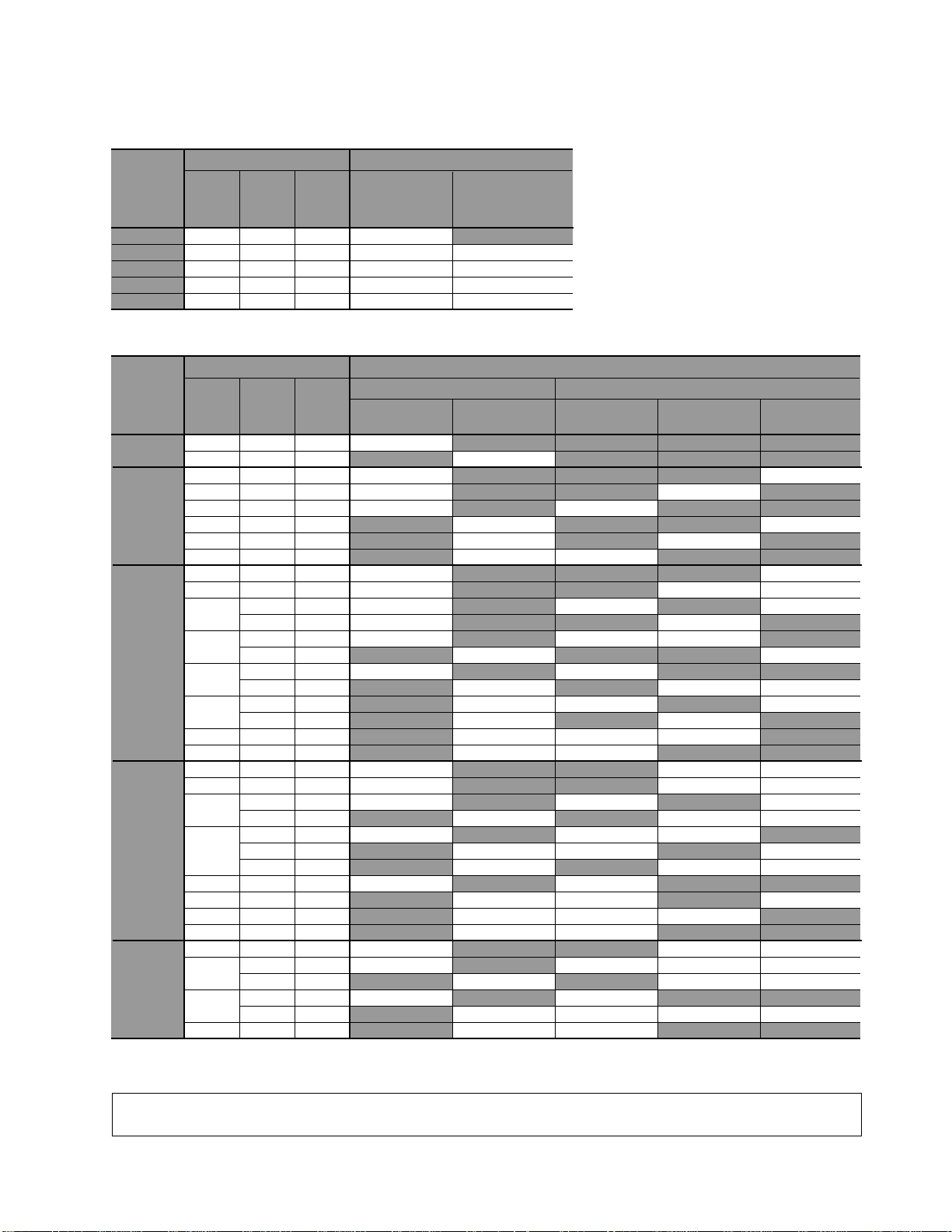
3. Combination of Boards
1) Combination of relay output type control and expansion boards
2) Combination of transistor output type control and expansion boards
Notes:
• You can combine both relay output type and transistor output type control boards and expansion boards.
• Intelligent boards can also be combined with the control board.
Total
number
of boards
1
2
3
4
5
Requested I/O point
Total Input Output
20
40
60
80
100
12
24
36
48
60
8
16
24
32
40
Control board
C20R series
(I: 12, O: 8)
Number of boards
Expansion board
E20R series
(I: 12, O: 8)
1
1
1
1
1
1
2
3
4
Total
number
of boards
1
2
3
4
5
Requested I/O point
Total Input Output
20
32
52
56
60
64
68
72
84
88
92
96
100
104
108
112
120
124
132
136
140
144
148
152
156
168
180
192
12
16
12
48
36
16
52
40
12
48
36
84
72
16
60
52
40
88
76
64
48
84
60
52
96
40
88
84
64
100
88
84
96
88
108
100
112
8
16
40
8
24
48
16
32
72
40
56
8
24
80
40
48
64
16
32
48
72
40
72
80
40
96
48
56
80
48
64
72
72
80
72
80
80
Control board
C20T series
(I: 12, O: 8)
1
1
1
1
1
1
1
1
1
1
1
1
1
1
1
1
1
1
C32T series
(I: 16, O: 16)
Number of boards
1
1
1
1
1
1
1
1
1
1
1
1
1
1
1
1
1
1
1
Expansion board
M1T-E
(I: 24, O: 16)
1
1
1
1
2
1
1
2
2
2
1
3
2
2
3
2
4
2
4
M1T-EI
(I: 36)
1
1
1
2
1
1
2
1
1
2
1
1
2
1
2
1
2
1
M1T-EO
(O: 32)
1
1
2
1
1
2
1
1
2
1
1
2
2
1
1
2
1
2
1
14
1-4. Programming Tools for FP-Ms
1-4. Programming Tools for FP-Ms
1. Programming Tools
Program editing can be done with a commercially available personal computer and FP Programmer II.
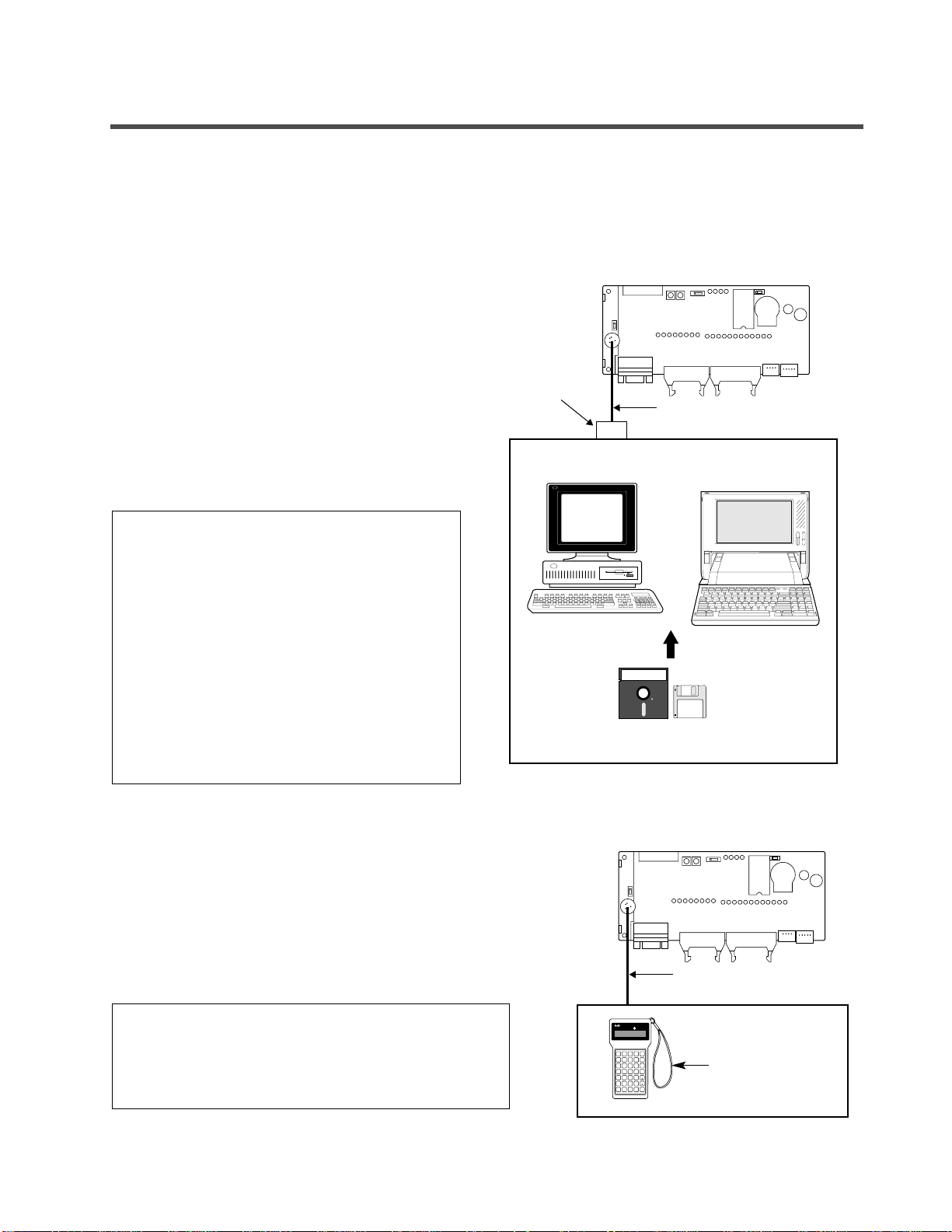
1) NPST-GR Software
Using the NPST-GR program editing software, programs can be easily created with any personal computer.
Necessary tools
• Computer: Commercially available personal computer
(IBM PC-AT or 100% compatible machine)
System required:
- Main memory: 550 KB or more free
- EMS: 800 KB or more free
- Hard disk space: 2 MB or more
- Operating system MS-DOS Ver. 3.30 or higher
- Video mode (display mode): EGA or VGA
• NPST-GR Software Ver. 3: AFP266538
• FP-M personal computer cable:
3 m/9.843 ft.: AFC8513
Notes:
2) FP Programmer II
With the hand-held FP Programmer II, such operations as writing,
reading, and retrieval of programs can be performed.
Necessary tools
• FP Programmer II: AFP1114
• FP-M peripheral cable (for FP Programmer II)
1 m/3.281 ft.: AFC8521
3 m/9.843 ft.: AFC8523
Notes:
• Refer to page 106, “5-7. How to Program ROM” and
“FP PROGRAMMER II Operation Manual”, for details
about writing programs using the FP Programmer II.
• Refer to page 239, “8-14. Product Types”, for details
about FP-M peripheral cable (for FP Programmer II).
• The .EXE files in NPST-GR Software are
compressed in the system disks. When
installing NPST-GR, you will have to expand
them.
• When using NPST-GR Software Ver. 2, refer to
page 220, “1. Differences Between NPST-GR
Ver. 2.4 and Ver. 3.1.”
• Refer to page 106, “5-7. How to Program
ROM” and “NPST-GR Manual”, for details
about writing programs using NPST-GR
Software.
• Refer to page 239, “8-14. Product Types”, for
details about FP-M personal computer cable
and RS232C interface adapter.
FP Programmer II
FP-M control board
RS232C
interface
adapter
FP-M personal computer cable
Commercially available personal computer
(IBM PC-AT or 100% compatible)
NPST-GR Software
FP-M control board
FP PROGRAMMER
ST
FN/P
X•WXANY•WYORR•WROTL•WL
FL
TM
NOT
STK
CT
(BIN)
T•SV
DT/Ld
IX/IY
C•EV
K/H
=
SHIFT
CDD<E>F
SC
(-)
89AB
OP
SRC
4 5 6 7
READ
0 1 2 3
(HELP)
(DELT)
ACLR
ENT
WRT
CLR
INST
FP-M peripheral cable
(for FP Programmer II)
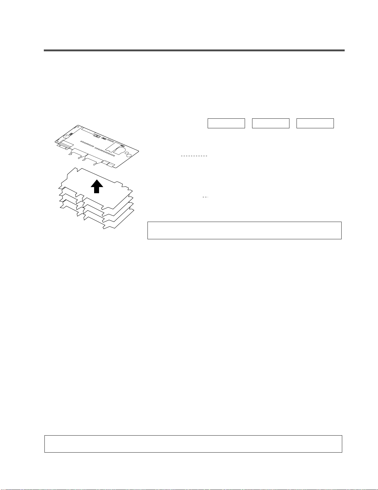
2. Tools for Making a Programmed ROM
• Using an FP ROM writer or a commercially available ROM programmer, the contents of the FP-M control board’s
internal RAM can be written to ROM (memory).
• The following types of ROM (memory) are available:
- Memory (EPROM): AFP5202
Memory for storing programs. Writing is done with an FP ROM writer or a commercially available ROM
programmer.
- Master memory (EEPROM): AFP5207
Memory for copying programs. Writing is done with attaching a master memory on the user memory socket.
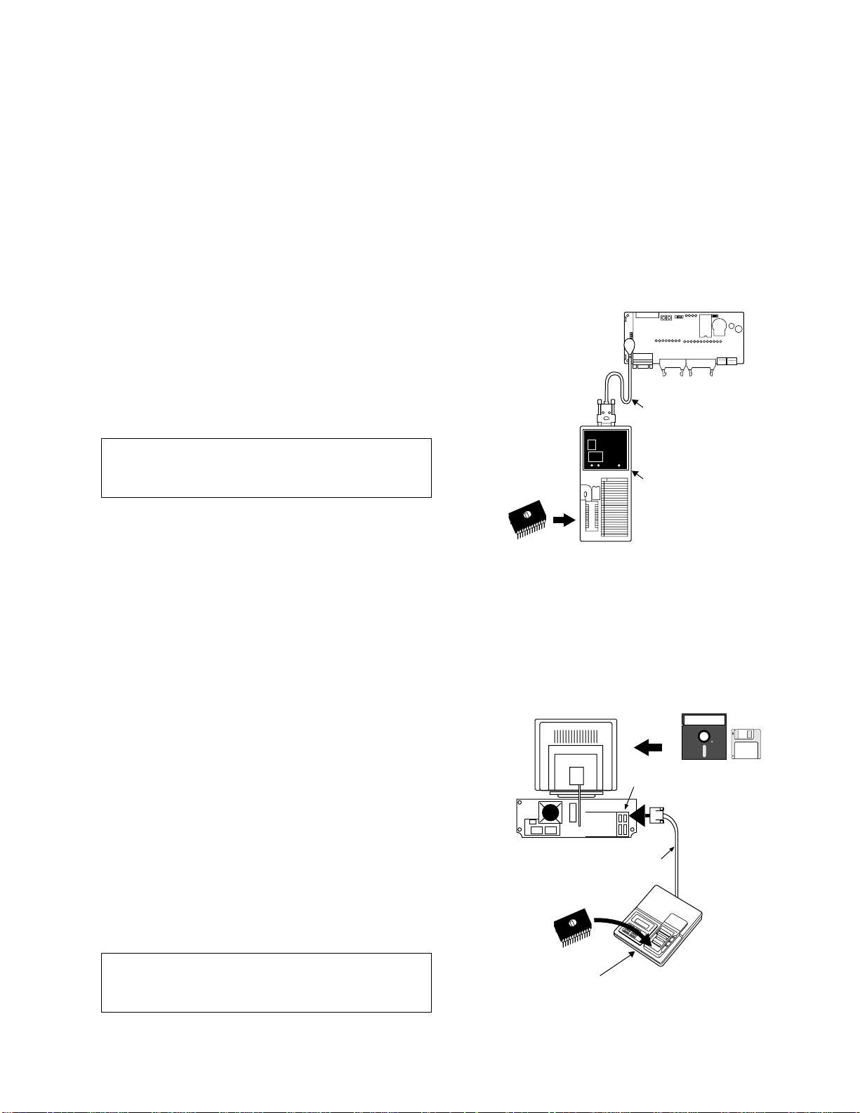
1) Writing a program to memory (EPROM) with an FP ROM writer
• The content of the FP-M control board’s internal RAM is written directly to the memory (EPROM).
Necessary tools
• FP ROM writer: AFP5651
• Memory (EPROM): AFP5202
• FP1 peripheral cable
0.5 m/1.640 ft.: AFP15205
3 m/9.843 ft.: AFP1523
Note:
2) Writing a program to memory (EPROM) with NPST-GR Software and a commercially
available ROM programmer
[Program with NPST-GR Software → Commercially available ROM programmer’s internal memory →
Memory (EPROM)]
Necessary tools
• Computer: Commercially available personal computer
(IBM PC-AT or 100 % compatible machine)
System required:
- Main memory: 550 KB or more free
- EMS: 800 KB or more free
- Hard disk space: 2 MB or more
- Operating system: MS-DOS Ver. 3.30 or higher
- Video mode (display mode): EGA or VGA
• NPST-GR Software Ver. 3: AFP266538
• RS232C cable: Needs to be made to match the specifications
of the commercially available ROM programmer.
• Commercially available ROM programmer:
We recommend Aval Data Corporation’s PECKER 11.
• Memory (EPROM): AFP5202
Note:
• The .EXE files of NPST-GR Software are
compressed in the system disks. When installing
NPST-GR, you will have to expand them.
• Refer to page 106, “5-7. How to Program ROM”
and “FP ROM WRITER Technical Manual”, for
details about programming ROM.
15
1-4. Programming Tools for FP-Ms
Memory
(EPROM)
FP-M control board
FP1
peripheral cable
National
abcdefg
abcdefgabcdefg
abcdefg
abcdefg
FP ROM writer
Commercially available
personal computer
(IBM PC-AT or 100% compatible)
RS232C interface
Rear view
RS232C cable
Memory
(EPROM)
Commercially available
ROM programmer
NPST-GR Software
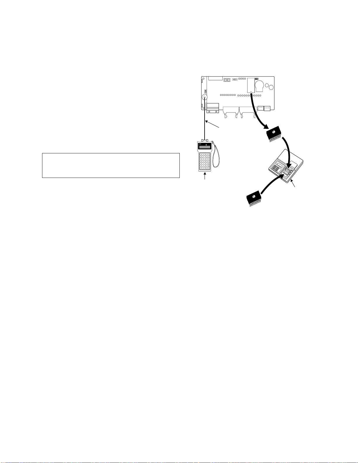
3) Writing a program to the memory (EPROM) via the master memory (EEPROM) with a
commercially available ROM programmer
[Program in FP-M control board’s internal RAM → Master memory (EEPROM) → Commercially available ROM
programmer’s internal memory → Memory (EPROM)]
Necessary tools
• FP Programmer II: AFP1114
• FP-M peripheral cable (for FP Programmer II)
1 m/3.281 ft.: AFC8521
3 m/9.843 ft.: AFC8523
• Commercially available ROM programmer:
We recommend Aval Data Corporation’s
PECKER 11.
• Master memory (EEPROM): AFP5207
• Memory (EPROM): AFP5202
Note:
• Refer to page 106, “5-7. How to Program ROM”
and “FP PROGRAMMER II Operation Manual”,
for details about programming ROM.
16
1-4. Programming Tools for FP-Ms
FP Programmer II
FP-M control board
FP-M peripheral cable
(for FP Programmer II)
FP PROGRAMMER
ST
FN/P
X•WXANY•WYORR•WROTL•WL
FL
TM
NOT
STK
CT
(BIN)
T•SV
DT/Ld
IX/IY
C•EV
K/H
=
SHIFT
CDD<E>F
SC
(-)
89AB
OP
SRC
4 5 6 7
READ
0 1 2 3
(HELP)
(DELT)
ACLR
ENT
WRT
CLR
INST
Memory
(EPROM)
Master memory
(EEPROM)
Commercially available
ROM programmer

CHAPTER 2
SPECIFICATIONS AND
PARTS TERMINOLOGY
2-1. Specifications of Control Board and Expansion Board.........18
1. General .............................................................................18
2. Performance......................................................................18
3. Input..................................................................................20
4. Output...............................................................................20
2-2. Parts Terminology .................................................................22
1. Control Boards..................................................................22
2. Expansion Boards.............................................................28
3. Board and Case Structure.................................................32
2-3. Dimensions............................................................................33
1. Board Type .......................................................................33
2. Case Type .........................................................................35

18
2-1. Specifications of Control Board and Expansion Board
2-1. Specifications of Control Board and
Expansion Board
1. General
2. Performance
Notes:
• No capacitor connected between DC terminal and frame ground terminal when the breakdown voltage
and insulation resistance test is performed.
• The actual number of points that can be used is the total number of I/O points of the control board and
the expansion board.
Item
Ambient temperature
Ambient humidity
Storage temperature
Storage humidity
Breakdown voltage
(See note.)
Insulation resistance
(See note.)
Vibration resistance
Shock resistance
Noise immunity
Operating environment
Rated operating voltage
Operating voltage range
Current consumption
Description
0˚C to +55˚C (32˚F to +131˚F)
30 % to 85 % RH (non-condensing)
–20˚C to +70˚C (–4˚F to +158˚F)
30 % to 85 % RH (non-condensing)
Transistor output type: 500 V rms for 1 min
Between DC terminal and frame ground terminal
Relay output type: 1,500 V rms for 1 min
Between output terminal and frame ground terminal
Min. 100 MΩ (measured with a 500 V DC megger)
Between DC terminal and frame ground terminal
10 Hz to 55 Hz, 1 cycle/min: double amplitude of 0.75 mm (0.030 in.), 10 min on 3 axes
2
Shock of 98 m/s
1,000 Vp-p with pulse widths 50 ns and 1 µs (based on in-house measurements)
Must be free from corrosive gases and excessive dust.
24 V DC
Controller power supply: 21.6 to 26.4 V DC
Input/output power supply: 20.4 to 26.4 V DC (C20T, C32T series)
Controller power supply: 0.2 A or less
Input/output power supply: Approx. 5 mA per an input point
or more, 4 times on 3 axes
22.8 to 26.4 V DC (C20R series)
Approx. 3 mA per an output point (except load current)
Item
Programming method
Control method
Program memory
Program capacity
Operation speed
Kinds of
instruction
External input (X)
External output (Y)
Basic
High-level
Relay symbol
Cyclic operation
Built in RAM (lithium battery backup)
EEPROM (master memory)/EPROM (memory) [optional items]
2.7 k type: 2,720 steps
5 k type: 5,000 steps
1.6 µs/step, basic instruction
81
111
208 points (See note.)
208 points (See note.)
Description

19
2-1. Specifications of Control Board and Expansion Board
Notes:
• The RS232C port and clock/calendar functions are available for the C types (C20RC, C20TC and C32TC).
• The pulse output function is available for the transistor output type.
• The two pulse outputs, Y6 and Y7 cannot be used at the same time.
Item
Internal relay (R)
Special internal relay (R)
Timer/counter (T/C)
Auxiliary timer
Data register (DT)
Special data register (DT)
Index register (IX, IY)
MCR points
Number of labels (JMP,LOOP)
Differential points (DF or DF
Number of step ladders
Number of subroutines
Number of interrupt programs
Advanced
control
functions
Adjustable input time filtering
Self-diagnosis function
Memory backup (at 25˚C)
High-speed counter
(1 channel)
Manual dial-set
register
Pulse catch input
Interrupt input
Periodical interrupt
RS232C port
(See note.)
Clock/calendar
(See note.)
I/O link
Pulse output
(See note.)
Constant scan
/)
Description
1,008 points
64 points
144 points
Unlimited number of points (0.01 s to 327.67 s)
2.7 k type: 1,660 words
5 k type: 6,144 words
112 words
2 words
32 points
64 points
Unlimited number of points
128 stages
16 subroutines
9 programs
Input: Count input (X0, X1)/reset input (X2)
Counting input mode: up mode, down mode, up/down mode, 2-phase mode
Counting range: –8,388,608 to 8,388,607
Max. counting speed: up/down mode 10 k Hz, 2-phase mode 10 k Hz
Min. input pulse width: 1 phase 50 µs • 2 phases 50 µs
2 potentiometers
Total 8 points (X0 to X7)
10 ms to 30 s interval
Communication speed: 300/600/1,200/2,400/4,800/9,600/19,200 bps
Communication distance per port: 15 m/49.213 ft.
Connector: D-SUB 9 pins connector
Clock/calendar function available
64 I/O points (32 inputs and 32 outputs) or 32 I/O points (16 inputs and 16 outputs)
2 points (Y6 and Y7)
Pulse output frequency range:
360 to 5,000 Hz/180 to 5,000 Hz/90 to 5,000 Hz/45 to 5,000 Hz
2.5 ms × set value (160 ms or less)
1 to 128 ms
Watchdog timer, battery detection, program check, and others
Approx. 27,000 h (C types: C20RC, C20TC and C32TC)
Approx. 53,000 h (except C types: C20R, C20T and C32T)
(For control board: 70 words, for intelligent boards: 42 words)

20
2-1. Specifications of Control Board and Expansion Board
3. Input
Notes:
4. Output
1) Relay output type
• Input response time can be changed using the input time filtering function to 1, 2, 4, 8, 16, 32, 64, or 128
ms in unit of 8 inputs. However, for expansion boards, the input response time is fixed at 2 ms (or less).
• The number of ON points must be decreased when the ambient temperature is high (between
40 ˚C/104 ˚F and 55 ˚C/131 ˚F).
Item
Rated input voltage
Operating voltage range
ON voltage/current
OFF voltage/current
Input impedance
24 V DC
20.4 V to 26.4 V DC
19.2 V or less/3 mA or less (19.2 V or less/3.6 mA: C32T series only)
2.4 V or more/1 mA or more
Control board: Approx. 4.8 kΩ
Description
Expansion board: Approx. 4.4 kΩ
Response time
ON ↔ OFF
2 ms or less (at normal input) (See note.)
50 µs or less (in setting high-speed counter)
200 µs or less (in setting interrupt input)
500 µs or less (in setting pulse catch)
Operating mode indicator
Insulation method
LED
Optical coupler
100
Number of ON
points/common [%]
50
Item
Rated operating voltage
Operating voltage range
Output type
Rated control capacity
Response time
Mechanical life time
Electrical life time
Surge absorber
Operating mode indicator
OFF → ON
ON → OFF
0
Ambient temperature [˚C (˚F)]
40 (104) 55 (131)
Description
24 V DC
22.8 V to 26.4 V DC
Normally open (1 Form A), 2 points/common
2 A 250 V AC, 2 A 30 V DC (resistive) (See note 1.)
8 ms or less
10 ms or less
2 × 10⁷ operations or more
105 operations or more
None
LED
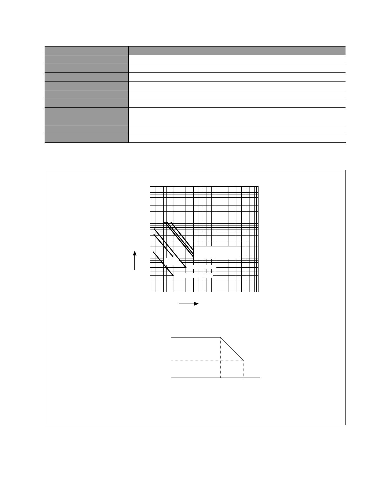
21
2-1. Specifications of Control Board and Expansion Board
2) Transistor output type (PNP and NPN open collector)
Notes:
1. Life characteristics of built-in relay (PA relay)
2. The maximum load current is kept within the following ranges when the ambient temperature is high.
3. Make the current for one common no more than the following values.
8 points/common circuit: 3 A/common
16 points/common circuit: 5 A/common
Item
Insulation method
Rated load voltage
Operating load voltage range
Max. load current
OFF state leakage current
ON state voltage drop
Response time
OFF → ON
ON → OFF
Surge absorber
Operating mode indicator
Optical coupler
24 V DC
20.4 V to 26.4 V DC
0.8 A/point (at 24 V DC) (See note 2.)
100 µA or less
1.5 V or less
1 ms or less
1 ms or less (100 µs or less: Y6 and Y7)
Zener diode
LED
100
times)
50
4
30
Frequency
(× 10
20
10
5
3
Description
125V AC resistive load
30V DC resistive load
125V AC
COSø=0.4
250V AC COSø=0.4
225V AC resistive load
30V DC T=7ms
0.5 1 2 3 10 100
Switching current (A)
0.8
Load
current (A)
0.35
0
Ambient temperature [˚C (˚F)]
40 (104) 55 (131)

22
2-2. Parts Terminology
2-2. Parts Terminology
1. Control Boards
1) C20R and C20RC types
■ C20R type
■ C20RC type
9 User memory socket (EPROM/EEPROM)
8 Potentiometers (V0 and V1)
7 Expansion connector
@ Memory selector (EPROM/EEPROM)
A Mode selector (RUN/REMOTE/PROG.)
B Operation monitor LEDs (RUN/PROG./
ERR./ALARM)
6 Baud rate
selector
(9600/19200)
4 Output terminal 3 Input terminal
1 Power supply
connector
2 Expansion power
supply connector
C Backup battery
holder
D Input indicators
(LED)
E Output indicators
(LED)
9 User memory socket (EPROM/EEPROM)
8 Potentiometers (V0 and V1)
7 Expansion connector
@ Memory selector
(EPROM/EEPROM)
A Mode selector (RUN/REMOTE/PROG.)
B Operation monitor LEDs (RUN/PROG./
ERR./ALARM)
6 Baud rate
selector
(9600/19200)
5 Programming
tool port
(RS232C)
F RS232C port
4 Output terminal 3 Input terminal
1 Power supply
connector
2 Expansion power
supply connector
C Backup battery
holder
D Input indicators
(LED)
E Output indicators
(LED)
5 Programming
tool port
(RS232C)
9600
19200
9600
19200
V0 V1
EPROM
V0 V1
EEPROM
EPROM EEPROM
RUN REMOTE PROG.
RUN REMOTE PROG.
(BATT.)
RUN PROG. ERR ALARM.
(BATT.)
RUN PROG. ERR ALARM.
 Loading...