

Panasonic FP-7818, FP-7830, FP-7845, FP-7850, FA-S620 Service Manual
...
ORDER NO. OED9909380B8
© 1999 Matsushita Graphic Communication
Systems, Inc. All rights reserved. Unauthorized
copying and distribution is a violation of law.
FP-7818/7824/7830/7835/7845/7850 Service Manual
Service Manual
Parts Manual
Plain Paper Copier
FP-7818/7824/7830
FP-7835/7845/7850
Staple Sorter
FA-S620/660
System Console
FA-DS72/82

WARNING
This service information is designed for experienced repair technicians only and
is not designed for use by the general public.
It does not contain warnings or cautions to advise non-technical individuals of
potential dangers in attempting to service a product.
Products powered by electricity should be serviced or repaired only by experienced
professional technicians. Any attempt to service or repair the product or products
dealt with in this service information by anyone else could result serious injury or
death.
For U.S.A
This equipment has been tested and found to comply with the limits for a Class A
digital device, pursuant to part 15 of the FCC Rules. These limits are designed to
provide reasonable protection against harmful interference when the equipment
is operated in a commercial environment. This equipment generates, uses, and
can radiate radio frequency energy and, if not installed and used in accordance
with the instruction manual, may cause harmful interference to radio
communications. Operation of this equipment on a residential area is likely to
cause harmful interference in which case the user will be required to correct the
interference at his/her own expense.
Any unauthorized changes or modifications to this equipment would void the users
authority to operate this device.
For U.S.A
This manual was developed and is supplied to authorized servicing dealers by
Panasonic Document Imaging Co. for the sole purpose of providing information
necessary for the equipment’s proper support. It is intended that this information
be confidential and may not reproduced without prior written consent from
Panasonic Document imaging Co. Panasonic Document imaging Co. reserves
the right to change any information enclosed herein without prior notification.
This manual was developed and is supplied to authorized servicing dealers by
Panasonic Co. for the sole purpose of providing information necessary for the
equipment’s proper support. It is intended that this information be confidential
and may not be reproduced without prior written consent from Panasonic Co.
Panasonic Co. reserves the right to change any information enclosed herein without
prior notification.

This manual dose not contain descriptions of PCB Connector and Signal
Information and Sub Assemblies Operation which are discribed and unchanged
in the FP-7718/7722/7728/7735/7742/7750 service manual. For those items not
covered in this manual, please refer to the FP-7718/7722/7728/7735/7742/7750
service manual or PCB repaire manual.

Contents / Index
I. Introduction
1.1 Specification ..................................................................................... 1-1
1.2 Features............................................................................................ 1-3
1.3 System Configuration ....................................................................... 1-4
1.4 Operation .......................................................................................... 1-6
(1) Special Effects Panel (FP-7818/7824/7830/7835) ...................... 1-7
(2) Communications Monitor (FP-7818/7824/7830/7835) ................ 1-8
1.5 Component Location......................................................................... 1-9
(1) Inner view.................................................................................. 1-10
(2) Fan/Motor Location ................................................................... 1-11
(3) Sensor Location ........................................................................ 1-12
(4) Solenoid/Clutch/Discharge lamp Location ................................ 1-13
(5) PCB Location ............................................................................ 1-13
1.6 Copy Process ................................................................................. 1-14
1.7 Precautions on Set Up.................................................................... 1-15
1.8 Precautions with Consumables ...................................................... 1-16
II. New Function
2.1 Image Control
Qualitative Reasoning Based Adaptive Controller .........
2-1
2.2 Toner Density Control....................................................................... 2-3
2.3 Trouble Avoidance Mechanism ........................................................ 2-5
2.4 Toner Recycling System................................................................... 2-7
2.5 Re-try Control for Paper Misfeed ...................................................... 2-8
III. Sub Assemblies
3.1 Main Drive......................................................................................... 3-1
(1) Detecting sheet bypass paper size ............................................. 3-2
(2) Developing .................................................................................. 3-3
(3) Supplying toner ........................................................................... 3-4
(4) Toner level detection................................................................... 3-5
(5) Temperature control.................................................................... 3-6
(6) Automatic detection of original paper size .................................. 3-7
(7) Adjusting quantity of light of AE sensor ...................................... 3-7
i
Introduction
Control
Functions
Sub Assemblies
Preventive
Maintenance
Troubleshooting
Unpacking/
Installation

IV. Preventive Maintenance
4.1 Precautions for Periodic Maintenance Service ................................. 4-1
4.2 Maintenance chart ............................................................................ 4-2
4.3 Cleaning Method............................................................................... 4-4
4.4 Disassembly and Re-assembly ........................................................ 4-7
(1) Multi-feed bypass ........................................................................ 4-8
(2) Paper feed unit.......................................................................... 4-11
(3) Developer unit ........................................................................... 4-14
(4) Fuser unit .................................................................................. 4-19
(5) Optics unit ................................................................................. 4-24
(6) Automatic duplex unit (ADU ).................................................... 4-32
(7) Main Body ................................................................................. 4-35
V. Troubleshooting
5.1 Service Mode.................................................................................... 5-1
(1) Service mode functions............................................................... 5-1
(2) Service mode procedure ............................................................. 5-2
(3) F4 mode ...................................................................................... 5-4
(4) F5 mode Copier function programming..................................... 5-16
(5) F6 mode Adjustment and programming.................................... 5-23
(6) F7 mode electronic counter....................................................... 5-29
(7) F8 mode copier operation adjustment ...................................... 5-31
(8) F9 Telephone# input ................................................................. 5-33
5.2 Self-diagnostics/Machine Malfunctions........................................... 5-34
(1) User error .................................................................................. 5-34
(2) Paper Jam................................................................................. 5-40
(3) Machine error ............................................................................ 5-43
5.3 User Preset Mode........................................................................... 5-58
VI. Unpacking/Installation
6. 1 Installation Requirements ............................................................... 6-1
6.2 Contents Check ............................................................................... 6-1
6.3 Unpacking........................................................................................ 6-1
6.4 Installation Procedure ...................................................................... 6-2
6.5 Adjustment....................................................................................... 6-7
6.6 White Density Adjustment.............................................................. 6-10
Caution:
Danger of explosion if battery is incorrectly replaced.
Replace only with the same or equivalent type recommended by the manufacturer.
Dispose of used batteries according to the manufacture's instructions.
For Sweden, and Denmark
SPECIALSÄKRING: ENDAST AV APPARATFABRINKANTEN LEVERERAD
SÄKRING FåR ANVÄNDAS.
VARNING!
Explosionsfara vid felaktigt batteribyte.
Använd samma batterityp eller ekvivalent typ som rekommenderas av
apparattillverkaren. Kassera använt batteri enligt fabrikantens instruktion.
ADVARSEL!
Lithiumbatteri—Eksplosionsfare ved
fejlagtig håndtering.
Udskiftning må kun ske med batteri
af samme fabrikat og type.
Lever det brugte batteri tilbage til
leverrandoren.
CAUTION!
Danger of explosion if battery is incorrectly replaced. Replace only with the
same or equivalent recommended by the manufacturer. Dispose of used
batteries according to the manufacturer’s instructions.
For Holland
Batterij niet
weggooien, maar
inleveren als KCA.
NL
ii

For U.K.
FOR YOUR SAFETY PLEASE READ THE FOLLOWING TEXT CAREFULLY.
This appliance is supplied with a moulded three pin mains plug for your safety and
convenience. A 13 amp fuse is fitted in this plug.
Should the fuse need to be replaced please ensure that the replacement fuse has a rating
of 13 amps and that it is approved by ASTA or BSI to BS1362.
Check for the ASTA mark or the BSI mark on the body of the fuse.
If the plug contains a removable fuse cover you must ensure that it is refitted when the fuse
is replaced.
If you lose the fuse cover the plug must not be used until a replacement cover is obtained.
A replacement fuse cover can be purchased from your local Panasonic Dealer.
IF THE FITTED MOULDED PLUG IS UNSUITABLE FOR THE SOCKET OUTLET IN YOUR
OFFICE THEN THE FUSE SHOULD BE REMOVED AND THE PLUG CUT OFF AND
DISPOSED OF SAFELY.
THERE IS A DANGER OF SEVERE ELECTRICAL SHOCK IF THE CUT OFF PLUG IS
INSERTED INTO ANY 13 AMP SOCKET.
If a new plug is to be fitted please observe the wiring code as shown below.
If in any doubt please consult a qualified electrician.
WARNING: THIS APPLIANCE MUST BE EARTHED.
IMPORTANT: The wires in this mains lead are coloured in accordance with the following
code:
Green and Yellow :Earth
Blue :Neutral
Brown :Live
As the colours of the wires in the main lead of this appliance may not correspond with the
coloured markings identifying the terminals in your plug, proceed as follows:
The wire which is coloured GREEN-AND-YELLOW must be connected to the terminal in the
plug which is marked by letter E or by the safety EARTH symbol “ ” or coloured GREEN or
GREEN-AND-YELLOW.
The wire which is coloured BLUE must be connected to the terminal in the plug which is
marked with the letter N or coloured BLACK.
The wire which is coloured BROWN must be connected to the terminal in the plug which is
marked with the letter L or coloured RED.
How to replace the fuse.
Open the fuse compartment with a screwdriver and replace the fuse.
Fuse
Fuse
iii


1-1
Introduction
Section I
Introduction
1. 1 Specifications
1.Type Desk Top
2.Copy process Electrostatic photographic method
3.Development process Two component magnetic brush
4.Maximum original size Ledger(11"x17") / A3(297 x 420mm)
5.Copy speed
FP-7818 FP-7824 FP-7830 FP-7835 FP-7845 FP-7850
(cpm)
<PU> <PG> <PU> <PG> <PU> <PG> <PU> <PG>
Ledger/A3 :
12.5 15.5/16.0 18.50/19.00 20/20.5
Legal/B4,FLS
:
14 17.5/17.0 21.00/20.50 23.5/23
Letter-R/A4R
:
15.5 19.5/19.0 24.00/23.50 28.5/27.5 43/41.5
Letter/A4 :
18 24.0 30.00 35 45 50
Invoice/A5 :
18 24.0 30.00 35 45 50
6.First copy time
FP-7818 FP-7824 FP-7830 FP-7835 FP-7845 FP-7850
(sec) letter/A4 size
4.8 4.0 4.0 4.0 2.9 2.9
without Auto mode
letter/A4 size
6.2 5.1 5.1 5.1 3.6 3.6
with Auto mode
7.Copy ratio Enlargement(fixed) : 2.00, 1.73, 1.41, 1.22, 1.15
Reduction (fixed) : 0.87, 0.82, 0.71, 0.58, 0.50
Zoom : 50%-200% (1%step)
8.Copy size Ledger/A3–Invoice/A5
9.Paper capacity Cassette :
550 sheets x 2 (550 sheets:FP-7818)
Multi-feed bypass : 50 sheets
10.Paper feed Front loading universal paper cassette
Multi-feed bypass tray
11.
Paper exit tray capacity
250 sheets
12.Paper weight Cassette : 16–24 lbs ( 60–90g/m
2
)
Bypass : 15–30 lbs (55–130g/m
2
)
13.Special paper OHP,Label paper, Tracing paper
(Through multi-feed bypass)
14.Continuous copying 1-999 reset to 1 (1-99 reset to 1 : FP-7818)

1-2
15.Fusing system Heat and Pressure
16.Photoreceptor Organic Photo Conductor(OPC)
17.Exposure control 7 step digital+Photo/Auto button
18.Warm up time FP-7818 approx. 40 sec.
FP-7824 approx. 50 sec.
FP-7830 approx. 75 sec.
FP-7835 approx. 75 sec.
FP-7845 approx. 180 sec.
FP-7850 approx. 270 sec.
19.Power consumption Less than 1.45 kW/1.5 kW
20.Power source AC120V 60Hz / AC220 - 240V 50Hz
21.Dimensions (W x D x H) 23.9" x 26.0" x 22.9" / 606 x 661 x 582 mm
(23.9" x 26.0" x 18.1" / 606 x 661 x 479 mm : FP-7818)
22.Weight (PU) (PG)
FP-7818 138.6 lbs / 64 kg
FP-7824 149.6 lbs / 70 kg
FP-7830 149.6 lbs / 70 kg
FP-7835 149.6 lbs / 70 kg
FP-7845 161 lbs / 73.5 kg
FP-7850 161.5 lbs / 73.7 kg
23.Ambient conditions Temperature : 50–86F/10–30 °C
Relative humidity : 30–80%
24.Optional accessories i-ADF FA-A888
ADF FA-A505
Sorter FA-S280
(10bin sorter: FP-7818/7824/7830)
FA-S575/S660/S680
(20bin sorter: except FP-7818)
System console FA-DS72: FP-7818/7824/7830/7835
FA-DS82: FP-7845/7850
LCC FA-MA301
* Specifications are subject to change without notice.

1-3
Introduction
1. 2 Features
• Introducing Qualitative Reasoning Based Adaptive Controller copy density
control
With Qualitative Reasoning Based Adaptive Controller used for copy density control,
optimum copies are maintained for a long time in variable environmental conditions.
• User friendly operation
The touch panel enables simple operation. (FP-7845/7850)
• Enhancements in serviceability
If a problem should occur the self diagnosis system will indicate which area is
responsible.
• Standard Automatic Duplexing (FP-7850)
An Automatic Duplex Unit is provided as standard, in addition to front paper loading
(550 sheets) + Multiple sheet bypass (50 sheets).
• Functional expansion through optional accessories
Equipping with the system stand and LCC allows a high copy volume
Maximum feed paper capacity
FP-7818 2,250 sheets : four drawers + multiple sheert bypass
FP-7824 2,800 sheets : five drawers + multipler sheet bypass
FP-7830/7835/7845
5,800 sheets : five drawers + LCC + multiple sheet bypass
FP-7850 5,250 sheets : four drawers + LCC + multiple sheet bypass
ADF and sorter can be connected with the main system easily by using exterior
connectors.
• Environmental considerations
Quieter operation, lower power consumption, a higher content of recyleable plastic
and our new Qualitative Reasoning Based Adaptive Controller. (FP-7830/7835/
7845/7850)
1-4
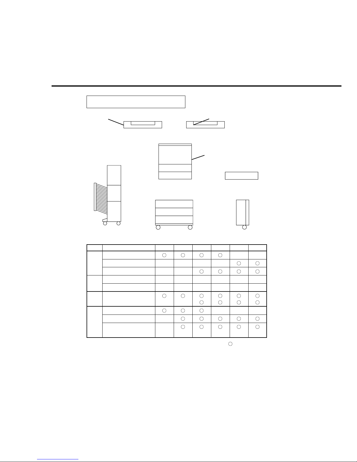
<Commonality of accessories>
1. 3 System Configuration
i-ADFADF
Main Unit
50
ADU
550
Sorter
Paper drawer
550
System console
550
Cover
Storage
LCC
3000
Accessories FP-7818 FP-7824 FP-7830 FP-7835 FP-7845 FP-7850
FA-DS72
xx
FA-DS82
xxxx
LCC ( FA-MA301 )
xx
Number of drawer 1 2 2 2
1 + ADU 1 + ADU
Auto Duplex unit (FA-MADM6)
x
Option Option Option
Standard Standard
ADF FA-A505
i-ADF FA-A888
xx
10bin sorter FA-S280
xxx
20bin sorter FA-S575
x
20bin staple sorter
x
FA-S660/S680
ADF
Copier
paper feed
System
console
Sorter
Key: = OKx = N/A
System Console FA-DS72: Storage tray,Cover x 1
( 2 drawers drive mechanism )
FA-DS82: 550 sheets paper drawer, Storage tray, Cover
( 3 drawers drive mechanism )

1-5
Introduction
Department counter 50 50 100 100 300 300
Cover, Interleaving, Presentation No * No * No * No * Yes Yes
Job memory 2 2 2 2 5 5
This Service Manual is based on the FP-7850.
To identify areas where the other models differ, please refer to this chart and the
Field Service Manual for each model.
FP-7818 FP-7824 FP-7830 FP-7835 FP-7845 FP-7850
Warm up time ( sec.) 40 50 70 70 180 210
First copy time ( sec.) 4.8 4.0 4.0 4.0 2.9 2.9
Paper feed cassette 1 2 2 2
1+ADU 1+ADU
System stand DS72 DS72 DS72 DS72 DS82 DS82
Copy speed 18 22 28 35 42 50
Control panel design LED LED
LCD display LCD display LCD touch panel LCD touch panel
Transfer corona cleaner No No No No Yes Yes
Drum separation finger No No No No Yes Yes
Fuser lamp 1 1 1 1 2 2
Process speed ( mm/sec. ) 170 210 210 210 340 340
Developer suction No No No No Yes Yes
Fresh toner recycling No No Yes Yes Yes Yes
Toner bottle life 10K 10K 20K 20K 20K 20K
Waste toner bottle capacity 10K 10K 120K 120K 120K 120K
PM cycle 80K 80K 120K 120K 120K 120K
[ Comparison of specifications ]
* Except OHP Interleaving
1-6
21
5
8
3
6
90
4
7
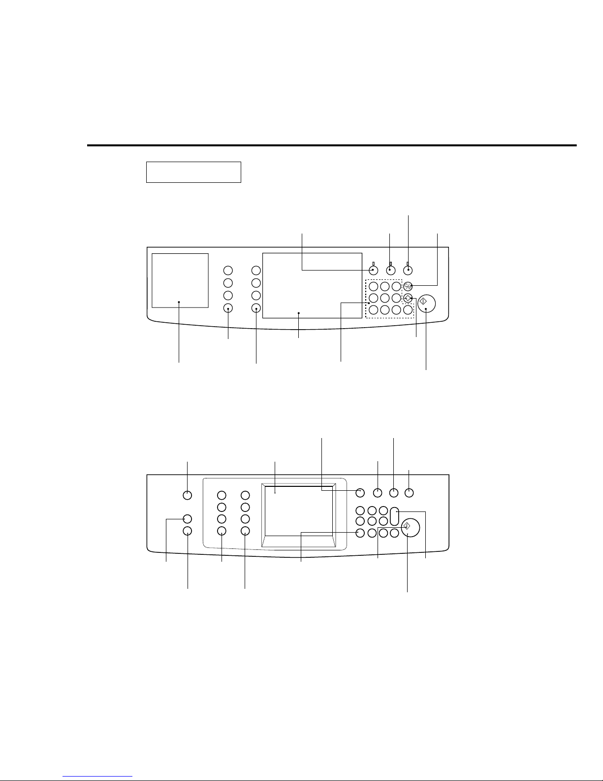
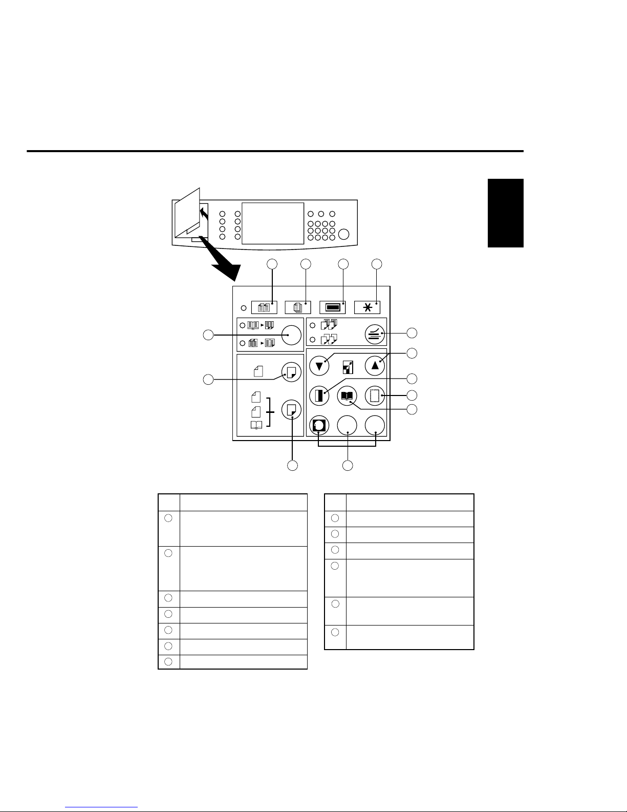
1. 4 Operation
Energy Saver
Interrupt Key
User Preset Key
Touch Panel Display Manual Key
Clear/Stop Key
Press to stop copy run
or clear copy count in
display.
Print Key
Reset Key
Press to reset all
features to initial
power-on state.
Original Size
Keys
Multi Size
Key
Job Memory Key Copy Size Keys
Quantity Keys
Ready Indicator
Ready: Green LED
Not ready: Red LED
Copy Reservation: Flashing
• FP-7845/7850
LEDGER
LEGAL
LETTER
INVOICE
1 2 3
4 5 6
7 8 9 0
Print Key
Recall Key
To recall the number
of copies selected
during a copy run.
Quantity Keys
Communications
Monitor
Copy Size Keys
Original Size
Keys
Special Effects Panel
• FP-7818/7824/7830/7835
Energy
Saverkey
Interrupt
Key
Reset Key
Clear/Stop
Key
1-7
Introduction
No. Keys
8 Edge Mode
9 Book Mode
10
Memory In/Job programs
11
Duplexing mode selection
(Except FP-7818/7824)
• Using ADU
12
2:1 Copy (Except FP-7818/7824)
• Using i-ADF
13
2-Page copy/2 in 1 mode selection
(2 in 1 : Except FP-7818/7824)
No. Keys
1 Multi-Size Feeding
(Except FP-7818/7824)
• Using i-ADF
2 Original Count
(Except FP-7818/7824)
• Using i-ADF and ADU 2 in 1
mode
3 Access
4 User Preset
5 OHP interleaving mode
6 Zoom
7 Margin Shift Mode
(1) Special Effects Panel (FP-7818/7824/7830/7835)
2
2
1
1
2
M
M1 M2
OHPOHP
OHPOHP
1 2 3
4
5
6
7
8
9
1011
12
13
321
1-8
%
mm
FP-7818/7824
FP-7830/7835
LEDGER
LEGAL
LETTER
LETTER
INVOICE
FP-7718
STAPLE
SORT
STACK
STAPLE
SORT
STACK
1 12 3 4 5 6 7
13
14
15
16
9 81710111812
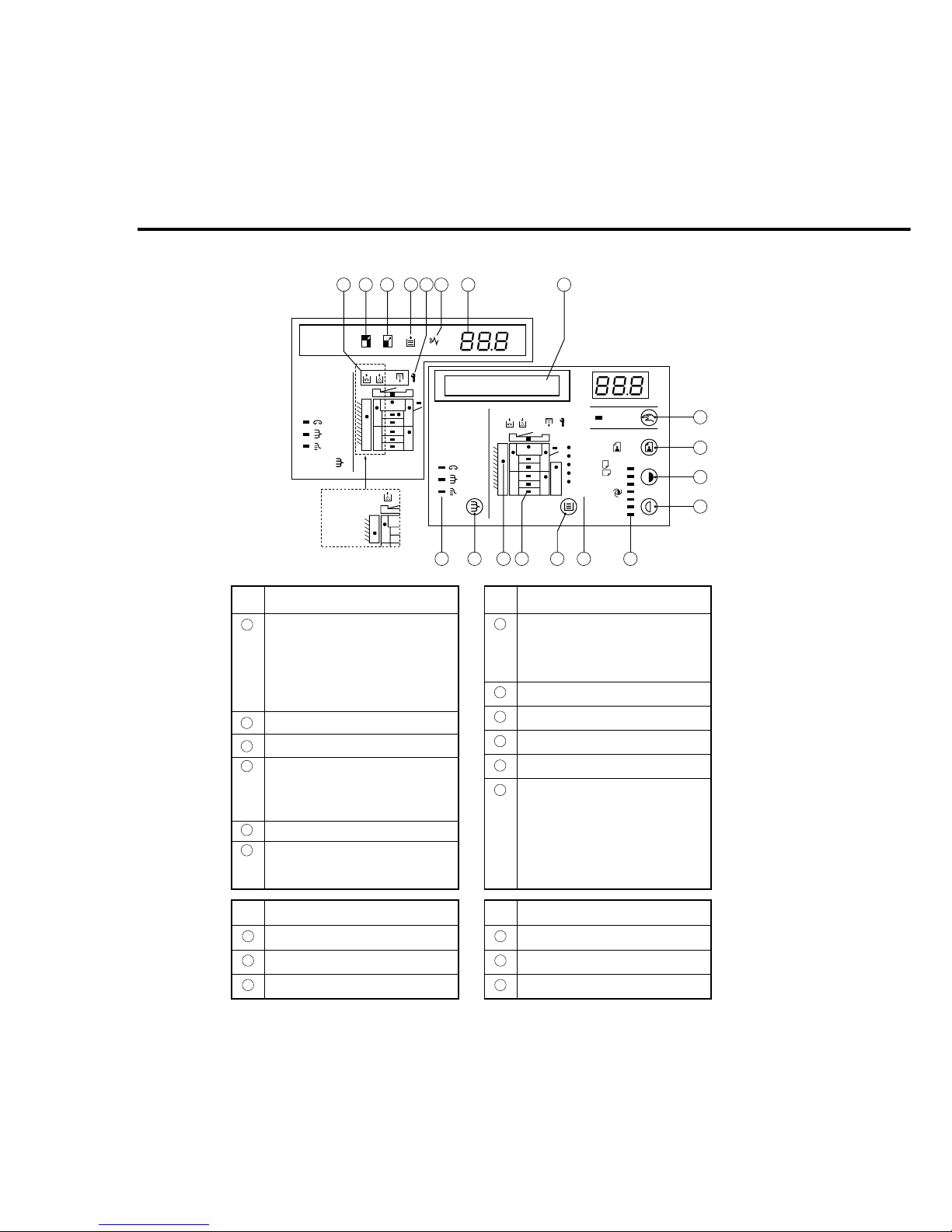
(2) Communications Monitor (FP-7818/7824/7830/7835)
No. Indicator
1 Adding
Paper
Toner
Staple (Except FP-7818)
Replacing
Waste Toner Bottle
2 Reduction
3 Enlargement
4 Service Call
• Flashes for routine maintenance.
• Lights steadily for duplex
maintenance
5 Paper Misfeed
6 Copy Count Display
Indicates number of copies, zoom
ratio and error code.
No. Indicator
7 Message Display
(FP-7830/7835)
Indicates procedures, functions
maintenance, etc.,
8 Exposure Indicator
9 Paper Size Indicator
10
Paper Drawer/Tray Indicator (–)
11
Paper misfeed location (•)
12
Mode Select Indicator
Staple Sort (Except FP-7818)
Sort
Group
No. Keys
13
Manual Key
14
PHOTO/AUTO
15
Exposure Control (DARK)
No. Keys
16
Exposure Control (LIGHT)
17
Paper Drawer/Tray
18
Mode Select Key
1-9
Introduction
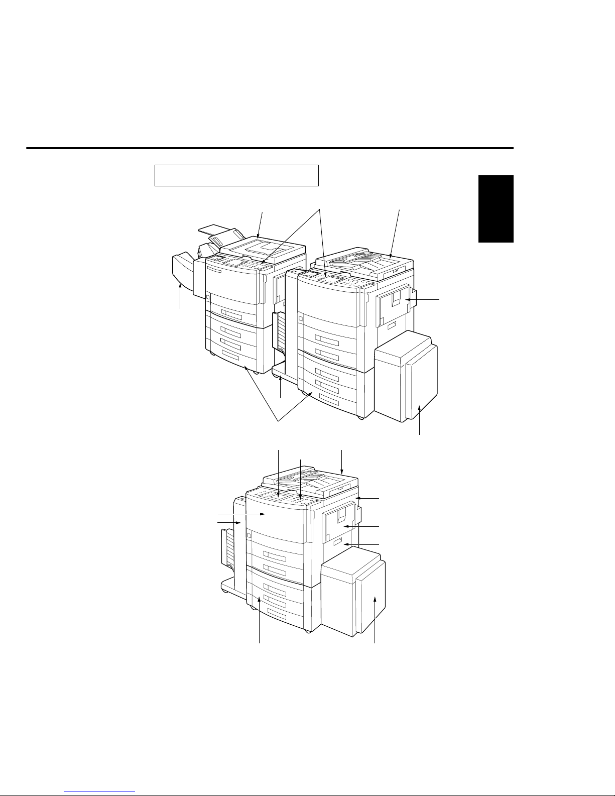
1. 5 Component Location
( Outer view )
Control Panel
i-ADF
ADF
FP-7818
System console
Sorter
LCC
(Except FP-7824)
Bypass
Sorter
FP-7824/7830/7835
LCD touch panel
Control panel
i-ADF
Right cover
Bypass
Paper feed cover
LCC
FP-7845/7850
System console
Front panel
Sorter
1-10
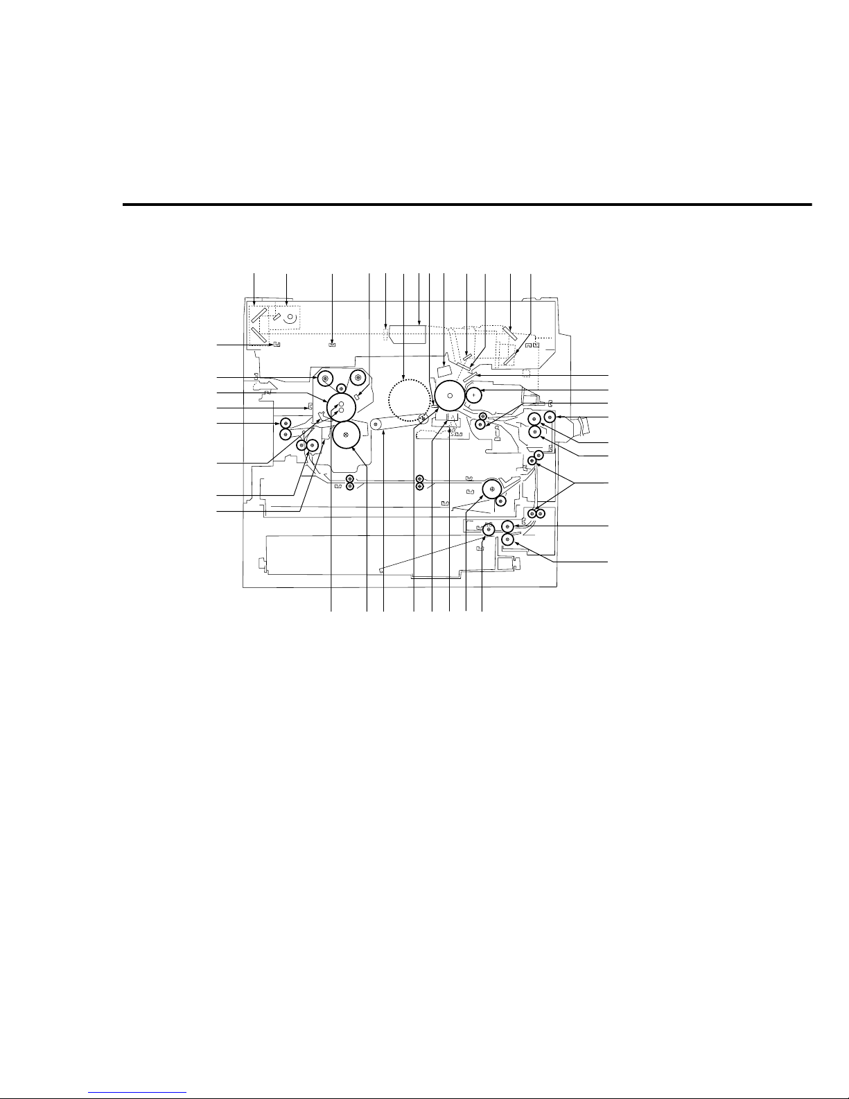
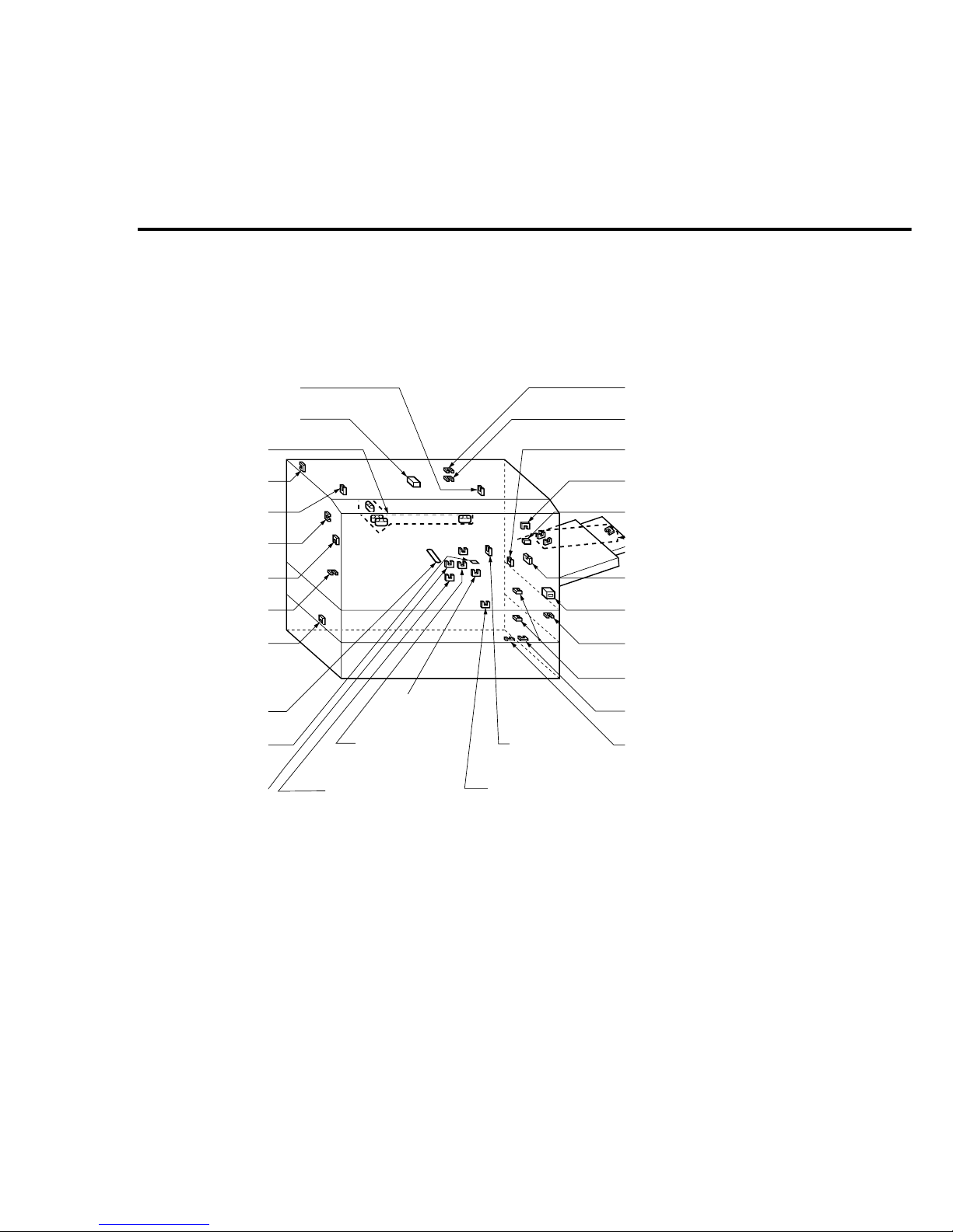
(1) Inner view
1 Half-speed unit
2 Full-speed unit
3 Lens Position sensor
4 Thermistor
5 AE Sensor
6 Main motor
7 Lens unit
8 Charge corona
9 No.6 mirror
10 Slit glass
11 No.4 mirror
12 No.5 mirror
13 LED array
14 Magnetic roller
15 Registration roller
16 Bypass pick-up roller
17 Bypass paper feed roller
18 Bypass DFP roller
19 Middle roller
20 Paper feed roller
21 DFP roller
22 Pick-up roller
23 ADU Paper feed roller
24 Corona cleaner
25 Transfer/Separation corona
26 Drum
27 Transfer belt
28 Pressure roller
29 Fuser lamps
30 Fuser separation finger (lower)
31 Reverse roller
32 Fuser separation finger (upper)
33 Paper exit roller
34 Paper exit sensor
35 Heat roller
36 Cleaning Web roller
37 Full-speed unit home postion sensor
38 Drum separation finger
234567388 9 10 11 12
13
14
15
16
17
18
19
20
21
222324252627
28
29
30
31
32
33
34
35
36
37
1

1-11
Introduction
Mirror stepping
motor
Optics drive
motor
Lens stepping
motor
Developer
cooling fan
Toner bottle
motor
Dust collecting
fan
ADU paper length guide
motor (FP-7850)
ADU paper width
guide motor
(FP-7850)
ADU drive motor
(FP-7850)
Optics fan
Optics fan
Main motor
Optics fan
Exhaust fan
Lifting motor
(lower stage)
Suction/Ozone
fan
(2) Fan/Motor Location
1-12
(3)Sensor Location
Mirror home position
Exposure lamp
home position
Platen cover
open/close
Platen cover
angle
AE (Automatic original
density sensor)
Original size
ADU
detection
(FP-7850)
Toner density
Copy density
ADU paper
length
(FP-7850)
ADU paper
pass 1 (FP-7850)
Paper exit
Lens home
position
Front cover
open/close
ADU paper width
(FP-7850)
Paper level
(lower stage)
ADU paper
detection
(FP-7850)
ADU paper
pass 2
(FP-7850)
Registration
roller paper pass
Paper detection
(lower stage)
Bottom plate upper limit
sensor (lower stage)
Middle roller paper pass
(upper/lower stage)
Waste toner
bottle
Total counter
Bypass paper
detection
Bypass paper size
Toner level
Toner bottle
home position
Paper feed cover
open/close

1-13
Introduction
(4) Solenoid/Clutch/Discharge lamp Location
Paper feed clutch
Registration roller clutch
Discharge lamp
Middle roller clutch
Bypass pick-up solenoid
Paper feed clutch (lower stage)
Separation
solenoid
Paper exit
solenoid
(FP-7850)
Power switch
Door switch
ADU clutch (FP-7850)
Pick-up solenoid (lower stage)
Recycle solenoid
(5) PCB Location
HVPS (High voltage
power supply)
LED array
Control panel 4
Control panel CPU
Control panel 3
Paper feed driver
LVPS (Low voltage
power supply)
AC driver
Main CPU
Automatic duplex
unit driver
(FP-7850)
1-14
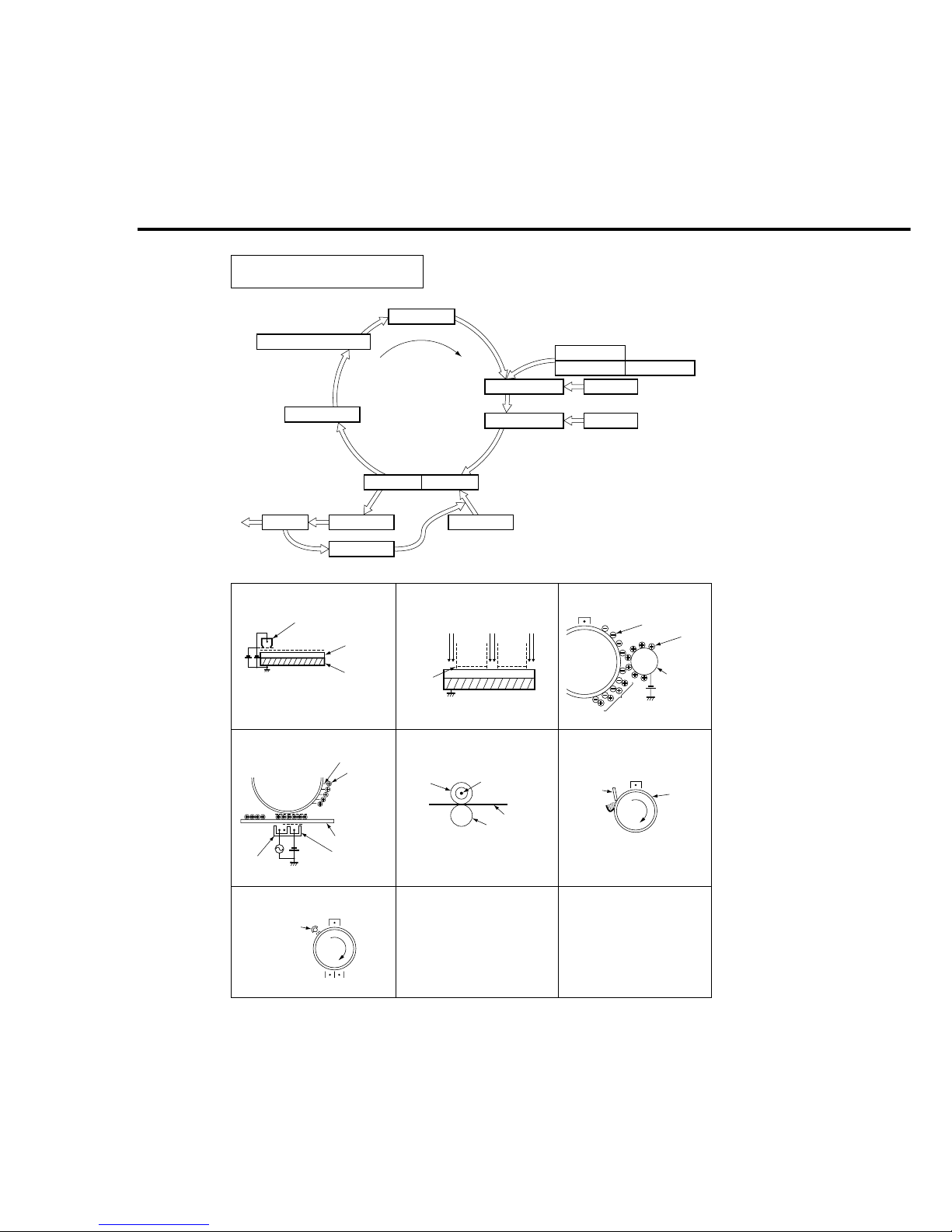
1. 6 Copy Process
Charger
Discharge lamp
Cleaning
Fusing
Exit
ADU
Paper feed
Separation
Transfer
Developer
Toner
Exposure
Original
Reduction Discharge
Trimming
–DC
Discharge lamp:
Transfer/Separation Fusing: Cleaning:
Primary Charge: Image Exposure: Developing:
Drum surface
approximately-800V DC
Charge corona
Drum
Latent
charge
image
Illumination
Magnetic
roller
Latent charge
image(–)
Discharge
lamp
Heat roller
Fuser lamp
Paper
Pressure
roller
Latent image
Transfer
corona
Cleaning
blade
Drum
Blacking prevention
Toner (+)
Toner
Paper
Separation
corona
1-15
Introduction
1. 7 Precautions on Set Up
Copy machine performance and the copy quality is subject to and dependant
on environmental conditions. To maintain good performance, quality, and safe
operation, observe the following precautions:
1) For safe operation and to avoid trouble do not install the system under the
following conditions:
• High temperature, high humidity, low temperature or low humidity
• The temperature or humidity varies suddenly
• Being exposed to direct sunlight
• Dusty space
• Badly ventilated location
• Exposed to chemical gases (such as ammonia gas)
• Exposed to strong vibration
• Directly exposed to direct wind (ex. outlet of air conditioner)
2) The weight of machine is 220lb(100 kg) or more with options. It must be placed
on a firm platform which is level.
3) The maximum power consumption is 1.45 kW. Use an independent power
supply of 120 V and 15 A (220-240V and 7A)or higher. (Do not use a extension
cord.)
4) Make sure the machine is properly grounded. (Do not ground to gas or water
pipe.)
• A ground terminal is provided on the back of the copier main body.
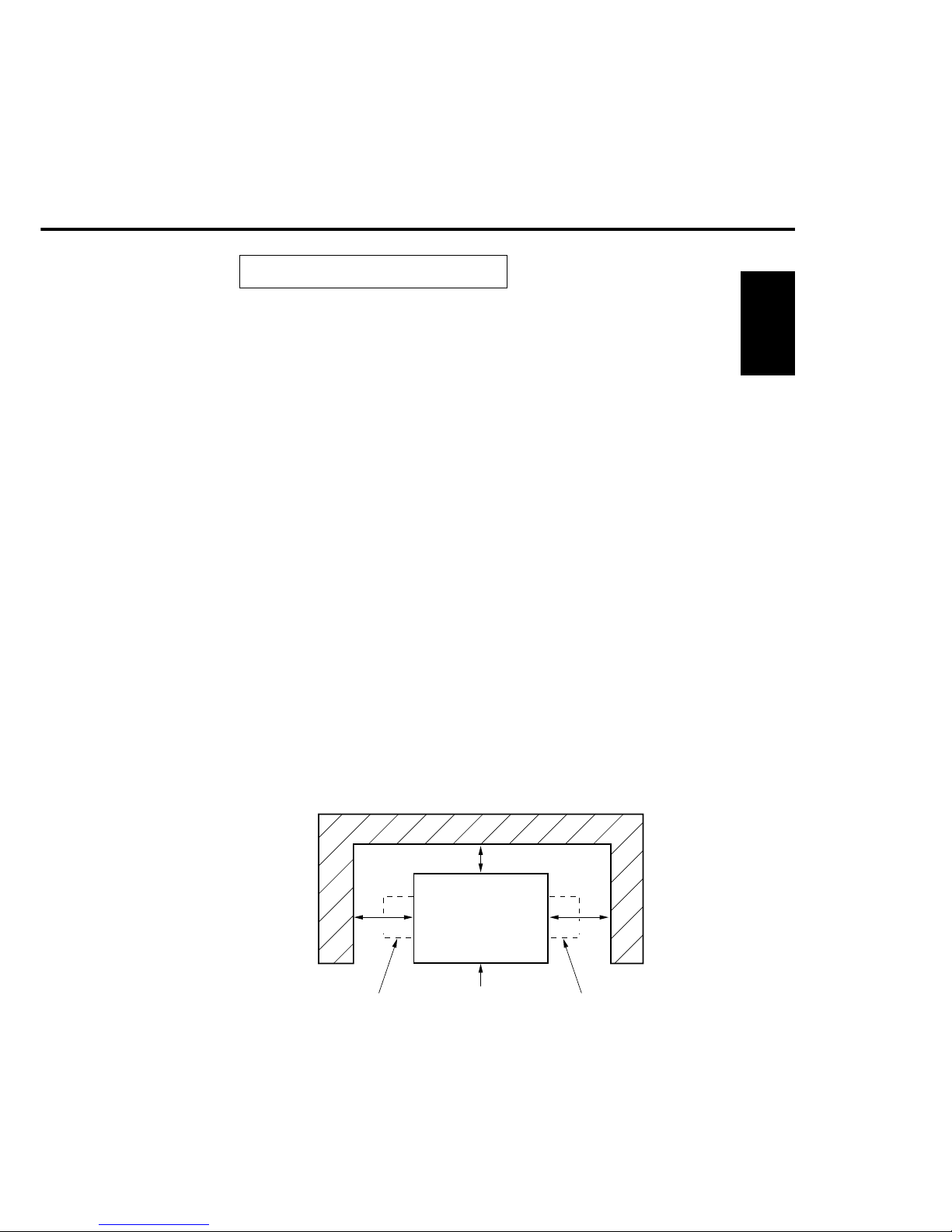
5) Install the machine with enough space around it.
4"/100 mm
14"/350mm
28"/700mm
Copier
Multi sheet bypassExit tray

1-16
1. 8 Precautions with Consumables
(1) Photoreceptor drum
• Do not touch the surface (with the hand or anything else).
• Stand the drum with the drum gear up for storage.
• Be careful not to smear with saliva, water, oil and so on.
• Do not place a where the temperature is high.
• Do not place it in strong light (such as direct sunshine or at window).
• Do not expose it to chemical gas or vapor.
• Do not store the developer unit with the photo receptor drum installed without
covering it with clean paper.
(2) Toner Developer
1) Do not mix different types of toner and developer.
• The machines are designed to use exclusive toner and developer for specific
models. Do not mix with toner and developer for other models.
2) Do not mix foreign materials.
Be careful not to include foreign materials in the toner and developer. If you
spilled toner or developer on a table or floor when adding toner or developer in
the developer unit, discard what was dropped. Such supplies may damage
the drum as well as cause other trouble with the image.
3) Do not place into other containers.
Toner and developer must not be placed into other containers, because some
containers may change the characteristics of the supply. Vinyl chloride
potentially changes the characteristics of supplies because of migrating
plasticizers.
4) Precautions on storage and transport
• Toner and developer additives are sensitive to temperature (high temperature
in particular) and humidity (high humidity in particular). Pay attention to the
following items for storage and transport.
• Store them in a dark and cool location (lower than 95 F/35 C) and out of direct
sunshine.
• Be careful not to expose them to rain or direct sunshine during transportation.
When delivered by truck the temperature inside must be not higher than 104
F/40 C.(Under the sun in summer, the inside temperature can typically be
140 F/60 deg.C or higher in a closed vehicle compartment.)

1-17
Introduction
• There are normally no special problems with storage and transport in a cold
climate but, store in a low humidity condition. Do not put supplies near heaters.
5) Safety and hygiene
Toner has the property of easily being wind blown. Toner on skin does not
cause any damage to health but, inhaling it is undesirable even if a powder is
simply dust. Therefore, be careful not to inhale toner .
• Handle the toner gently when changing cartridges, and developer when pouring
in the developer unit. If you have breathed in a lot of toner by mistake, rinse
out your mouth with water completely. Any toner on the skin should be washed
off with soapy water.
• Toner stuck on clothing must be removed in a dry condition (by a vacuum
cleaner, brush, or beating,) and then washed with soapy water. Wiping off with
benzine, alcohol, or thinner is not recommended because it may partially melt
the components of toner even more, resulting in a harder stain and spot.
• Toner spilled must be cleaned with a vacuum cleaner, and then wiped with a
cloth dampened with a neutral detergent and wrung out.
• If exposed to flames toner and developer will burn. Keep these supplies away
from open flames.
• Any wasted consumables (photo receptor, developer and toner) should be
recycled.
• Wear rubber gloves, eye protection and so on before handling any solvents
such as IPA.

Control
Functions
2-1
Section II
Control Functions
2. 1 Image Control
Qualitative Reasoning Based Adaptive Controller
• Even if the toner density is at it's standard level, the copy image may vary with time
depending on the characteristics of drum and the environmental variations.
To prevent this change, the copy density sensor which is installed under the
developer unit controls the image to stablize the copy image.
• Controlling the image
During initialization after turning on the power, the copy density sensor reads the
white density, medium density (line pattern density patch) and black density
developed on the drum surface.These three values are compared with the ideal
gamma curve stored in the copiers memory.
The copier detects the amount offset from the standard gamma curve (such as "a
little background" or "light image") and calculates the variables for copy density
control in accordance with Qualitative Reasoning Based Adaptive Controller. In
this way it finds the optimum compensation values to tighten the gamma curve for
maintaining peak copy quality.
By means of this process, copy quality is stabilized by the various compensations
enabled by Qualitative Reasoning Based Adaptive Controller adjustment in image
production.
• The control of the gamma curve stabilizes copy quality by monitoring three points
of copy quality (white density, medium density and black density) and has a direct
effect on background, solid area density and good reproduction of fine lines
regardless of environmental changes and variation with time and copy volume.

2-2
• Qualitative Reasoning Based Adaptive Controller
Qualitative Reasoning Based Adaptive Controller is adaptive control on the basis
of quantative reasoning theory. While successively reasoning and learning the
change of process characteristics regardless of environmental changes and the
variations with time and the number of copies on the copier, the system reads the
patch marks and determines the best values of exposure and surface potential to
establish the best gamma curve for optimum copy quality.
• Qualitative Reasoning Based Adaptive Controller is applied at the following intervals.
a) During initialization after turning on the power.
b) After every 1,000 sheets following execution of Qualitative Reasoning Based
Adaptive Controller
(But, every 200 sheets following the execution of F8-09 for the next
500 sheets)
c) After turning on the power (up to 200 copies)
d) After replacing the toner bottle (up to 200 copies)
• Copy density detecting sensor
Two sensors for detection of copy density are used, one for white density, and line
pattern density and one for detection of black density. (Temperature and humidity
sensors are not used.)
• To correct for toner build up on the sensor, clean the sensor at the same time as
the replacement of the drum. The system provides a measured amount of light
and detects the reflected light. The resultant value is used for sensor compensation.
This becomes the reference value.
• As the reference value of the white density changes, various components are
adjusted according to characteristics of the gamma curve.
Reference F5-25: Qualitative Reasoning Based Adaptive Controller
Operation ON/OFF
F mode F6-80: Automatic compensation value (read only)
F6-81: Automatic compensation value (read only)
F6-82: Automatic compensation value (read only)
F6-28: White density reference value
(set by Qualitative Reasoning Based Adaptive
Controller)
F6-29: Black density reference value
(set by Qualitative Reasoning Based Adaptive
Controller)
Control
Functions
2-3
Amount of carrier passing TDC sensor Toner density condition Sensor output voltage
Less High Lower than normal
Much Low Higher than normal
<Control>
The following controls are necessary for normal control of toner density
1) Automatic adjustment of TDC sensor gain (during execution of F8-C09)
(to attain the standard reference level).
2) Maintain the standard level by control of toner density during use.
<Explanation of the control system>
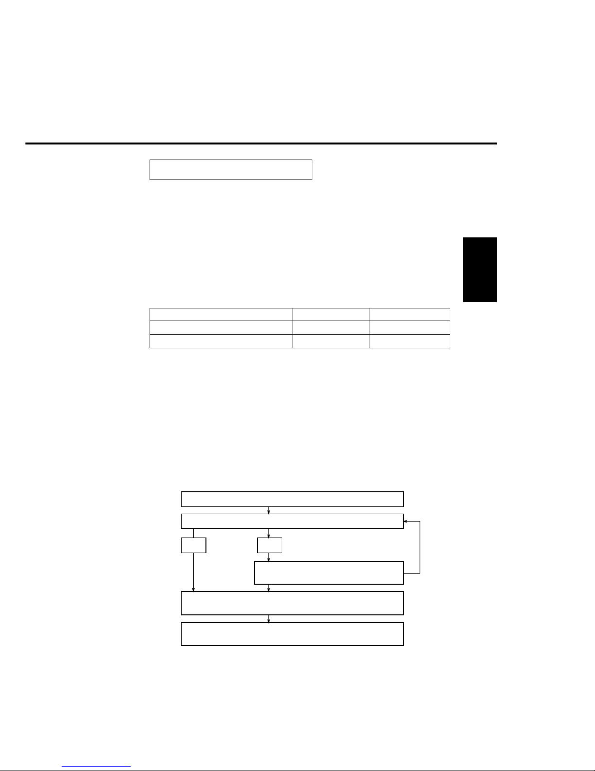
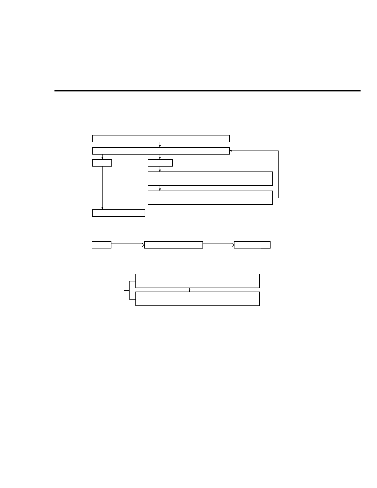
1) Automatic adjustment of TDC sensor gain
Automatically adjust the reference through the TDC sensor by executing service
mode F8-09.
The operation flow is as shown below.
2. 2 Toner Density Control
To keep toner density(toner carrier ratio) in the developer unit constant, the TDC
sensor (toner density sensor) which is installed under the developer unit detects the
amount of carrier in the developer unit to control the toner density.
<Fundamentals>
The change in magnetic flux density in accordance with the amount of carrier
(magnetic power) in the developer (mixture of toner and carrier) is detected by the
TDC sensor and is converted to a voltage to control the toner density.
<Change of toner density and change of TDC sensor output voltage>
F8-09 start
CPU will check toner density sensor output. (2.5 V)
CPU will adjust sensor gain
control signal
Memory number will be changed to new number in memory.
(F6-21 or F6-26)
Toner density sensor output voltage will be adjusted to 2.5 V
Yes
No
2-4
2) Maintain standard toner density
While checking the output voltage of the TDC sensor for every copy, control the
timing of toner supply to the developer unit so that the output voltage is 2.5V at
all times to keep the toner density constant.
Supply toner: supply from reserve tank for 6 seconds
(amount of toner supply: approx. 1.4 g)
Rotate bottle for 7 seconds: supply toner to reserve
tank. (Toner is not supplied to developer unit.)
Check TDC sensor output voltage at copying (or mixing).
Is the measured output voltage over 2.5V?
Do not supply toner.
Note) During bottle rotating, toner is not supplied.
YES
NO
(Reference 1) Toner supply route
(Reference 2) Forced toner supply
Note: Bottle rotation means toner is being added to the reserve tank, not the
developer unit. This is not a final confirmation for proper TDC adjustment.
Reserve tank (hopper)
Developer unit
Bottle
Supply toner: supply for 4 seconds from reserve tank.
(amount of toner supply: approx. 1.1 g)
Rotate bottle for 7 seconds: supply toner to reserve tank.
(Toner is not supplied to developer unit.)
Perform twice.

Control
Functions
2-5
2. 3 Trouble Avoidance Mechanism
When some malfunction happens, this mechanism allows regular copy operation
without error conditions (service man call) (providing the malfunction does not affect
the basic copying operation and the appropriate function is not selected).
<Indication>
Appropriate function selected
Appropriate function not selected
The selected function is unavailable, Normal indication of copying
repair is necessary,
select others.
"(EX-XX)"
EX-XX XXXXXX
(Error code) (Electronic counter value at malfunction)
User mode
Service mode
Note: Only 30 records can be stored. Earliest records are
replaced by new ones as space is required.
 Loading...