

Page 1
Page 2

Safety Precautions
Observe the following notices to ensure personal safety or to prevent accidents.
To ensure that you use this product correctly, read this User’s Manual thoroughly before use.
Make sure that you fully understand the product and information on safety.
This manual uses two safety flags to indicate different levels of danger.
WARNING
If critical situations that could lead to user’s death or serious injury is assumed by
mishandling of the product.
-Always take precautions to ensure the overall safety of your system, so that the whole
system remains safe in the event of failure of this product or other external factor.
-Do not use this product in areas with inflammable gas. It could lead to an explosion.
-Exposing this product to excessive heat or open flames could cause damage to the lithium
battery or other electronic parts.
CAUTION
If critical situations that could lead to user’s injury or only property damage is
assumed by mishandling of the product.
-To prevent excessive exothermic heat or smoke generation, use this product at the values
less than the maximum of the characteristics and performance that are assured in these
specifications.
-Do not dismantle or remodel the product. It could cause excessive exothermic heat or smoke
generation.
-Do not touch the terminal while turning on electricity. It could lead to an electric shock.
-Use the external devices to function the emergency stop and interlock circuit.
-Connect the wires or connectors securely.
The loose connection could cause excessive exothermic heat or smoke generat ion.
-Do not allow foreign matters such as liquid, flammable materials, metals to go into the inside
of the product. It could cause excessive exothermic heat or smoke generation.
-Do not undertake construction (such as connection and disconnection) while the power
supply is on. It could lead to an electric shock.
Copyright / Trademarks
-This manual and its contents are copyrighted.
-You may not copy this manual, in whole or part, without written consent of
Works SUNX Co., Ltd.
-Windows is a registered trademark of Microsoft Corporation in th e United States and other
countries.
-All other company names and product names are trademarks or registered trademarks of
their respective owners.
Panasonic Electric
PLC_ORG
Page 3

Table of ContentsFP2−CCU
Table of Contents
Interchangeability with the FP3 and Precautions iii...............................
Chapter 1 Functions of Computer Communication Unit
1.1 Functions and Features 1 − 3............................................
1.1.1 Functions and Features 1 − 3....................................
1.1.2 Unit Part No. 1 − 3..............................................
1.2 Unit Operation 1 − 4....................................................
1.2.1 Operation Overview 1 − 4........................................
1.3 Restrictions on Units Combination 1 − 6...................................
1.3.1 Restrictions on Current Consumption 1 − 6........................
1.3.2 Restrictions on Installation Position 1 − 6..........................
1.3.3 Restrictions on Number of Units that can be Installed 1 − 7...........
1.4 Communication Conditions and Restrictions Relating to Functions 1 − 8.......
1.4.1 Precautions when Using the FP2 CPU Unit−11− 8.................
1.4.2 Precautions when Using the FP2 CPU Unit−21− 9.................
Chapter 2 Names and Functions of Part
2.1 Names and Functions of Parts 2 − 3......................................
2.1.1 Names and Functions of Parts 2 − 3..............................
2.1.2 Operating Status LEDs 2 − 4.....................................
2.1.3 COM.1 and COM.2 Ports (9 Pins) 2 − 5............................
2.1.4 Transmission Format Setting Switch 2 − 6.........................
Chapter 3 Confirming Unit Settings and Design Contents
3.1 Setting the Transmission Speed (Baud Rate) and Transmission Format 3 − 3..
3.1.1 Transmission Format Setting Using Switch 3 − 3....................
3.2 Confirming the I/O Allocation and Root No. 3 − 5...........................
3.2.1 I/O Allocation 3 − 5.............................................
3.2.2 Confirming Root No. 3 − 6.......................................
i
Page 4

FP2−CCUTable of Contents
Chapter 4 RS232C Port Wiring
4.1 RS232C Port Signals 4 − 3..............................................
4.2 Wiring between RS232C Ports 4 − 5......................................
4.2.1 Connecting to a Personal Computer 4 − 5.........................
4.2.2 Connections with Operation Display Panel 4 − 6....................
4.2.3 Connections with RS232C Devices 4 − 7..........................
4.2.4 Modem Connections 4 − 8.......................................
Chapter 5 Troubleshooting
5.1 Operation if an Error Occurs 5 − 3........................................
5.1.1 If the ALARM LED on the Computer Communication Unit
Lights 5 − 3....................................................
5.1.2 If the ERROR LED on the Computer Communication Unit
Lights 5 − 4....................................................
5.2 What to Do if an Error Occurs 5 − 5.......................................
5.2.1 If the ALARM LED on the Computer Communication Unit
Lights 5 − 5....................................................
5.2.2 If the ERROR LED on the Computer Communication Unit
Lights 5 − 5....................................................
5.2.3 Communication is Inhibited 5 − 6.................................
5.2.4 If an Error Response is Returned to the Host Side 5 − 6.............
Chapter 6 Specifications
6.1 Specifications 6 − 3.....................................................
6.2 Table of MEWTOCOL Command 6 − 4....................................
6.2.1 MEWTOCOL−COM Commands 6 − 4.............................
6.3 Table of MEWTOCOL−COM Error Code 6 − 5..............................
Record of changes R − 1..............................................
ii
Page 5

Interchangeability with the FP3 and PrecautionsFP2−CCU
Interchangeability with the FP3 and Precautions
Hardware interchangeability
The user should be aware that there are some differences between the FP2 and FP3
Computer Communication Units.
− The DIP switch settings are different.
With the FP2 Computer Communication Unit, only the transmission speed and the
character bit can be set with the DIP switches. The settings for the parity, the stop bit
length, and whetheror not the CS and CD control signals are effective are fixed as shown
in the table below.
− There is no reset switch.
The FP2 Computer Communication Unit has no reset switch.
− Connections with serial devices are made in the same way for both units.
The specifications for the RS232C interface of the FP2 Computer Communication Unit
are the same as those for the FP3.
− Two ports are provided, a “COM.1” port and a “COM.2” port.
However, the COM.1 port is restricted on the functions as below.
COM.1 COM.2
Computer link function Available Available
Modem connection Not available Available
Data transmission Not available Available
Hierarchy command Not available Available
Software interchangeability
The software is interchangeable between the FP2 and FP3 Computer Communication
Units.
− Program methods on the host side are largely the same.
There are some differences in the transmission formats, as described below.
iii
Page 6

Comparison of specifications between the FP2 and FP3 Computer
Communication Units
Setting item Set value FP2 FP3
No. of ports — 2 ports 1 port
Transmission speed (Baud rate) 19,200 bits/s
9,600 bits/s
4,800 bits/s
2,400 bits/s —
1,200 bits/s —
600 bits/s —
300 bits/s —
Transmission speed (Baud rate)
when modem is connected
Character bit 7−bit
Parity None —
Stop bit 1−bit
Control signals CS and CD Invalid
Reset switch — None Provided
9,600 bits/s
2,400 bits/s —
8−bit
Odd
Even —
2−bit —
Valid —
φ φ
φ φ
φ φ
φ
φ φ
φ φ
φ φ
φ φ
φ φ
φ
φ
φ
φ
—
φ
φ
φ
φ
φ
FP2−CCUInterchangeability with the FP3 and Precautions
φ : Default setting, or can be set using DIP switches
—: Cannot be set
iv
Page 7

Chapter 1
Functions of Computer Communication Unit
1.1 Functions and Features 1 − 3..........................
1.1.1 Functions and Features 1 − 3..................
1.1.2 Unit Part No. 1 − 3............................
1.2 Unit Operation 1 − 4..................................
1.2.1 Operation Overview 1 − 4......................
1.3 Restrictions on Units Combination 1 − 6.................
1.3.1 Restrictions on Current Consumption 1 − 6.......
1.3.2 Restrictions on Installation Position 1 − 6........
1.3.3 Restrictions on Number of Units that can be
Installed 1 − 7................................
1.4 Communication Conditions and Restrictions
Relating to Functions 1 − 8............................
1.4.1 Precautions when Using the
FP2 CPU Unit−11− 8........................
1.4.2 Precautions when Using the
FP2 CPU Unit−21− 9........................
Page 8

FP2−CCUFunctions of Computer Communication Unit
1 − 2
Page 9
Functions of Computer Communication UnitFP2−CCU
1.1 Functions and Features
1.1 Functions and Features
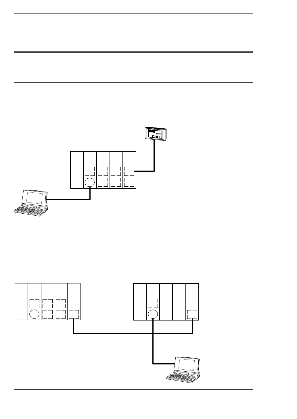
1.1.1 Functions and Features
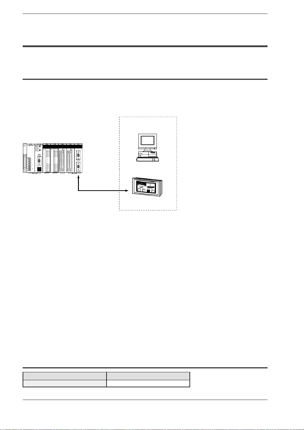
The FP2 Computer Communication Unit is designed for use with the FP2/FP2SH
progra,mmable controller. It is used as a communication interface that allows data to be
read and written between an RS232C device such as a personal computer or display
panel, and a CPU unit.
Host computer
(Personal computer)
Operation
display panel
RS232C
Can be connected to a display panel and computer.
Enables a 1:1 connection to a display panel and computer. No software program is
needed for communication.
Economical peer−to−peer communication with a personal computer is possible.
This unit can be directly connected with a personal computer through RS232C to collect
and write data from it without building up a large−scale network.
One unit is equipped with two ports.
One unit is equipped with two RS232C interface ports.
No communication program is needed on the PLC. (Computer link function)
The PLC automatically returns responses using the FP series’ MEWTOCOL
communication protocol so that there is no need to prepare a communication program
at the side of the PLC.
Connection with modem (Only COM. 2)
It is possible to receive data over telephone lines from another PLC, by connecting
modem with your PLC. (Receiving only)
1.1.2 Unit Part No.
Name Part No.
Computer Communication Unit FP2−CCU
Two D−sub connectors (9−pin) are provided as accessories with the unit.
1 − 3
Page 10
Functions of Computer Communication Unit
FP2−CCU
1.2 Unit Operation
1.2 Unit Operation
1.2.1 Operation Overview
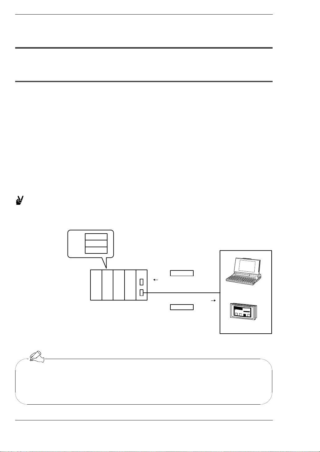
The Computer Communication Unit reads and writes data and contacts of the CPU unit
by the host computer, through an RS232C interface.
When a command is sent from a host side, a response is returned from the PLC side.
The formats of commands and responses are determined by the MEWTOCOL, which
is the communication protocol for the FP series of PLCs.
Programs for host side devices such as computers and display panels are created in
accordance with the protocol “MEWTOCOL”.
More than 20 types of commands are available, including commands for reading and
writing the data area and contacts, etc.
No program is necessary on the PLC side in order to carry out communication.
Example:
When the contents of the data registers are read to a host
computer:
10
5
3
Command
%01#RDD0000000001**
RS232C
%01$RD05000A0062
Response
C
R
Computer
C
R
メ
イ
ン
メ
ニ
ュ
ー
を
選
択
照
明
制
御
空
調
制
御
〜
〜
Display panel
DT0
DT1
DT2
Tip
The display panel for the FP series was designed ahead of time in conformance with the MEWTOCOL communication protocol, so there is no need
to take the contents of commands into consideration.
AM
5
1
5
3
時
館
内
掲
¦
板
〜
〜
〜
〜
〜〜
〜〜
L
〜〜
1 − 4
Page 11
FP2−CCU
Functions of Computer Communication Unit
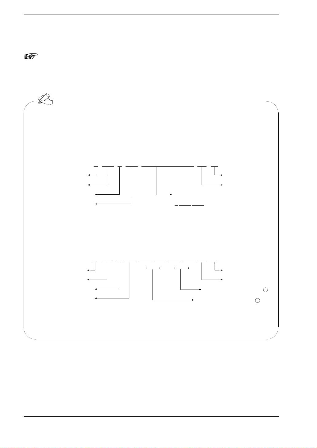
Note
This unit does not support extension header (<). Use the Multi
Communication Unit.
Tip
MEWTOCOL communication protocol for FP series are generally configured
as shown below.
Command format (Example showing command for reading data)
% 0 0000000001
1
#RD CRD
Start code
Destination
Indicates command
Type of command
Data specification
*D 00000 00001 indicates data registers DT0 to DT1.
1.2 Unit Operation
*
*
End code
BCC (Block Check Code)
*RD stands for “Read Data”.
Response format (Example of response to data reading command)
%0 0 5 0 0 6 21
Source
Indicates response
Type of command
$RD CR
(lower) (higher)
0A00
(lower) (higher)
Content of data that was read
Content of data that was read
End codeStart code
BCC (Block Check Code)
2
1
1 − 5
Page 12
Functions of Computer Communication Unit
1.3 Restrictions on Units Combination
FP2−CCU
1.3 Restrictions on Units Combination
1.3.1 Restrictions on Current Consumption
The power supply (5 V DC) used to drive the internal circuits of the Computer
Communication Unit and other units is provided from the power supply unit, through the
backplane.
The overall current consumption, including the current used by other units, should not
exceed the rated capacity of the power supply unit.
Unit name Part No. Current consumption (at 5 V DC)
FP2 Computer Communication Unit FP2−CCU 60 mA or less
For information on the internal current consumptions of other units, please refer to the
“FP2/FP2SH Hardware Manual” and the manuals of the pertinent units.
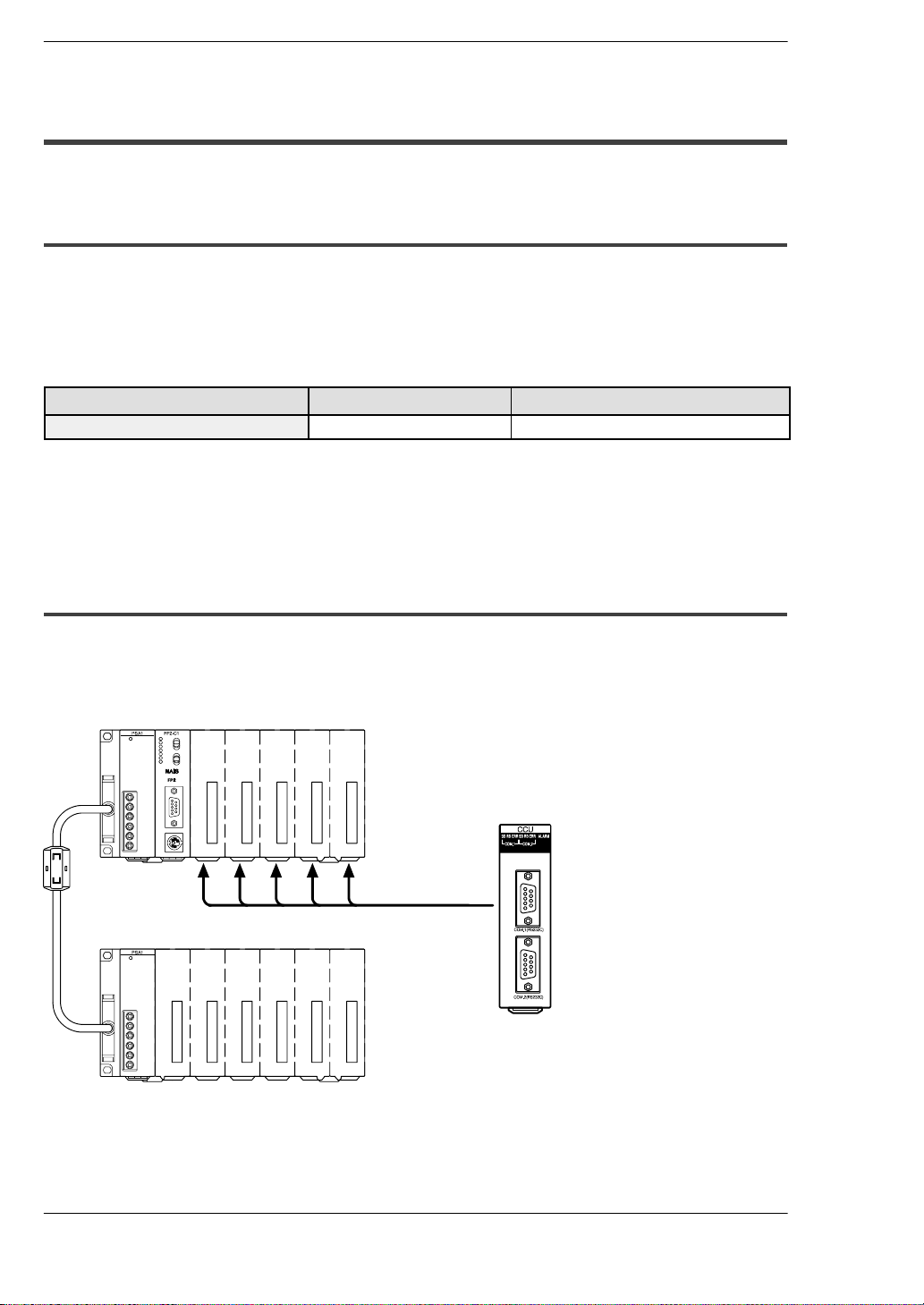
1.3.2 Restrictions on Installation Position
The Computer Communication Unit can only be installed on the CPU backplane side.
It should not be installed on the expansion backplane. Also, it should be installed to the
right of the power supply unit and the CPU unit.
CPU backplane
Computer
Communication Unit
Can be installed
only on the CPU
backplane
Expansion
cable
Expansion backplane
1 − 6
Page 13

FP2−CCU
Functions of Computer Communication Unit
1.3 Restrictions on Units Combination
1.3.3 Restrictions on Number of Units that can be Installed
The number of Computer Communication Units that can be installed is as shown in the
table below.
Unit type When FP2 CPU unit is used When FP2SH CPU unit is used
Computer Communication Unit Only one.
Multi−wire Link Unit
(MEWNET−W mode)
Up to three units can be used if they
are used within the range of restrictions described under “section 1.4
Communication Conditions and Restrictions Relating to Functions”.
Up to three units, in combination with
Computer Communication Units.
Tip
The above restrictions do not apply to Multi−wire Link Units set to the
MEWNET−F mode and MEWNET−W2 mode.
Up to five units, using Computer Communication Units and Multi−wire Link
Unit (MEWNET−W mode) in combination.
Note
If the FP2 CPU unit is being used, make sure the restrictions
relating to the following communication conditions have been
carefully confirmed when deciding the number of units to be
installed.
1 − 7
Page 14
Functions of Computer Communication Unit
FP2−CCU
1.4 Communication Conditions and Restrictions Relating to Functions
1.4 Communication Conditions and Restrictions
Relating to Functions
1.4.1 Precautions when Using the FP2 CPU Unit −1
If the processing of commands and responses sent from a host computer or display
panel extends over multiple frames, a busy error (error code 53) will be returned to other
ports if communication is currently being carried out on one port, and communication will
be inhibited on those other ports. Combinations to which this restriction applies are
shown in the diagram below.
メ
イ
ン
メ
ニ
ュ
5
ー
1
5
3
時
AM
を
選
択
照
明
制
御
空
調
制
御
館
内
掲
¦
板
〜〜
〜
L
〜〜
〜
〜
〜
〜
〜
〜〜
Power
supply
CCU CCU CCU
CPU
For example, during the time that a
program is being read at the tool port
of the CPU unit, a communication er-
AAA
B
A
BBB
ror will occur at the display panel
connected to the COM.1 port of the
Computer Communication Unit.
Group A Group comprising the tool port of the CPU unit and the COM.1 port.....
of the Computer Communication Unit
Group B Group comprising the COM. port of the CPU unit and the COM.2.....
port of the Computer Communication Unit
A similar restriction also applies if access is being made from another station connected
with the link unit.
Unit No. 1 (source station) Unit No. 2 (other station)
Power
supply
CPU
B
A
CCU CCU
AA
BB
MW
Power
supply
CPU
B
A
MW
When remote programming is being carried out from
another station connected with a Multi−wire Link Unit
(MW), a communication error will occur at the Group A
ports on the source station side.
1 − 8
Page 15
FP2−CCU
Functions of Computer Communication Unit
1.4 Communication Conditions and Restrictions Relating to Functions
Tip
− “Multiple frames” means that, if a command or response exceeds 118
bytes, the command or response is divided into multiple segments and
transmitted or received.
For example, this applies in cases such as when a program is read from
a tool port, when commands, which continuously read multiple data, are
transmitted from a host side.
− If using the FP2SH CPU unit, the above restriction does not apply.
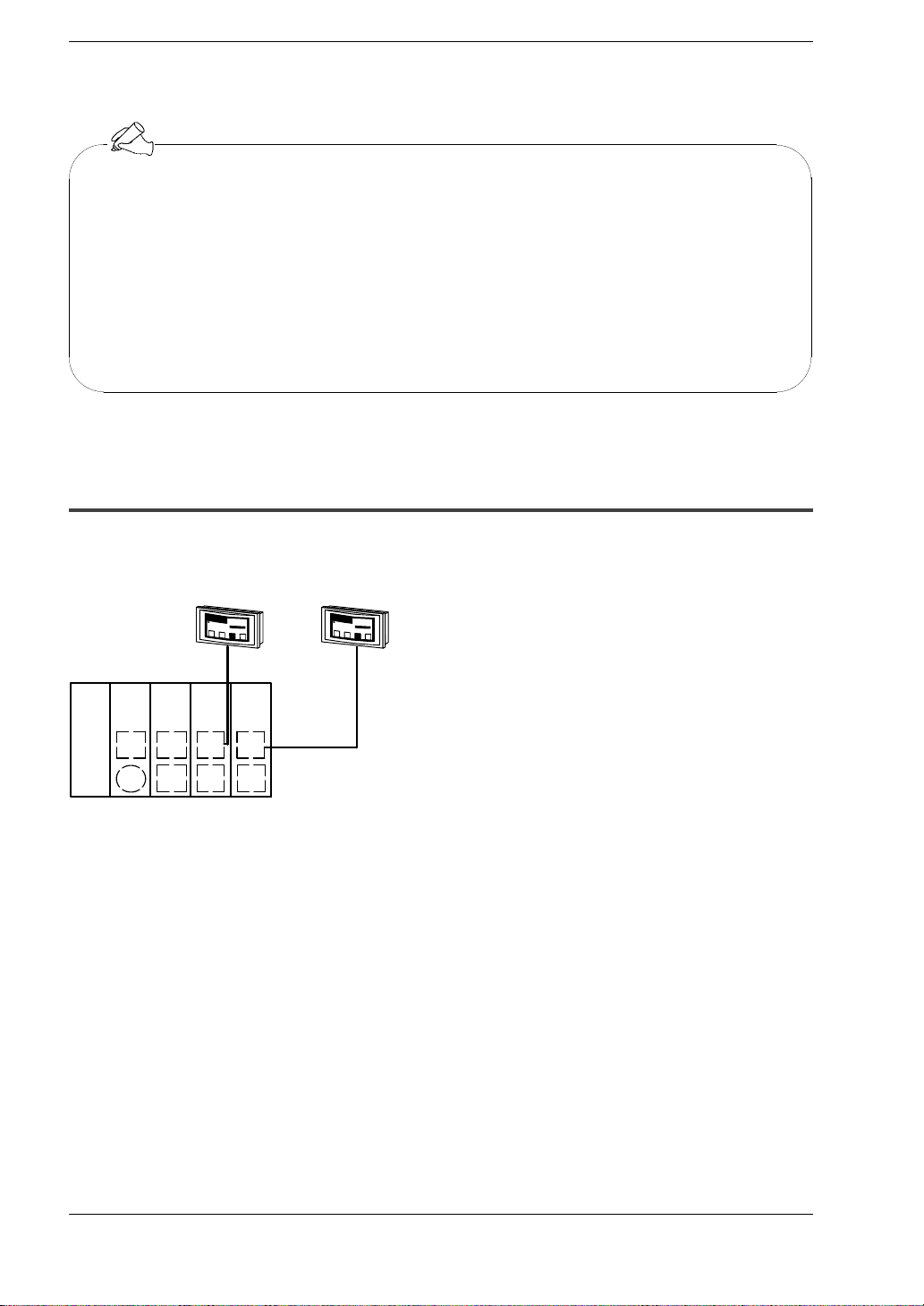
1.4.2 Precautions when Using the FP2 CPU Unit−2
Of the commands sent from a host computer or display panel, if the monitor commands
(the MC, MD, and MG codes) are used, they cannot be read accurately if two or more
devices within the same group are connected.
Power
supply
CCU CCU CCU
CPU
CC
B
DD
A
Group A CPU unit tool port.....
Group B CPU unit COM. port.....
Group C COM.1 port group of Computer Communication Unit.....
Group D COM.2 port group of Computer Communication Unit.....
メ
イ
ン
メ
ニ
5
ュ
ー
1
5
3時
A
M
を
選
択
照
明
制
御
空
調
制
御
館
内
掲
¦
板
〜〜
〜
L
〜〜
〜
〜
〜
〜
〜
〜〜
メ
イ
ン
メ
ニ
5
ュ
ー
1
5
3時
A
M
を
選
択
照
明
制
御
空
調
制
御
館
内
掲
¦
板
〜〜
〜
L
〜〜
〜
〜
〜
〜
〜
〜〜
For example, if two or more display panels in the
same group are connected and the command
sent from the display panel side is a monitor com-
C
mand, it cannot be read accurately.
D
1 − 9
Page 16

Functions of Computer Communication Unit
FP2−CCU
1.4 Communication Conditions and Restrictions Relating to Functions
A similar restriction also applies if access is being made from another station connected
with the link unit.
メ
イ
ン
メ
ニ
ュ
5
ー
1
5
3時
A
M
を
選
択
照
明
制
御
空
調
制
御
館
内
掲
¦
板
〜〜
〜
L
〜〜
〜
〜
〜
〜
〜
Unit No. 1 (source station) Unit No. 2 (other station)
Power
CPU
supply
CCU CCU
MW
〜〜
Power
CPU MW
supply
CC
B
A
DD
If remote programming is used to change the monitoring destination from another station connected with the
Multi−wire Link Unit (MW), the monitoring destination
of the Computer Communication Unit COM.1 port of
the source station side will end up being changed.
Note
If a monitor command is used for a port in the same group,
registered data will be rewritten in sequential order starting from
the most recent data, and different data will end up being
monitored.
D
C
Tip
− Monitoring commands are commands used to implement monitoring
after the contact or data to be monitored has been registered on the
PLC side.
− The above restriction does not apply if the FP2SH CPU unit is being
used.
1 − 10
Page 17

Chapter 2
Names and Functions of Parts
2.1 Names and Functions of Parts 2 − 3....................
2.1.1 Names and Functions of Parts 2 − 3............
2.1.2 Operating Status LEDs 2 − 4...................
2.1.3 COM.1 and COM.2 Ports (9 Pins) 2 − 5..........
2.1.4 Transmission Format Setting Switch 2 − 6.......
Page 18

FP2−CCUNames and Functions of Parts
2 − 2
Page 19

2.1 Names and Functions of Parts
2.1.1 Names and Functions of Parts
Names and Functions of PartsFP2−CCU
2.1 Names and Functions of Parts
Front Back
1
Operating status LEDs
This displays the operating status of the unit, such as communication conditions
and error/alarm situations.
2
COM.1 port (RS232C) and COM.2 port (RS232C)
These ports are used to connect the RS232C connector of an RS232C device such
as a personal computer or display panel, using a shielded cable.
3
Transmission format setting switch
These switches are used to set the transmission speed (baud rate) and character
bit for the COM.1 and COM.2 ports. The values set by these switches are
automatically reflected when the power supply is turned on. For other information
on the transmission format, please see page 3 − 3.
4
Backplane connector
This connector is used to connect the Computer Communication Unit to the
backplane.
Tip
The settings of the transmission format setting switches become effective
when the power supply is turned on.
2 − 3
Page 20

Names and Functions of Parts
Send
Data
monitor
Receive
Data
monitor
Communication
error
Send
Data
monitor
Receive
Data
monitor
Communication
error
FP2−CCU
2.1 Names and Functions of Parts
2.1.2 Operating Status LEDs
These display the operating status of the unit, such as communication conditions and
error/alarm situations.
Display Operation
ALARM (red)
COM. 1 SD (green)
RD (green)
ERR (red)
COM. 2 SD (green)
Lighted: Unit error (lights on watchdog timer error)
Not lighted: Goes out when there is no error
Flashes while data is being sent
Goes out when no data is being sent
Flashes while data is being received
Goes out when no data is being received
Lights if communication error occurs
Goes out if normal frame is received
Flashes while data is being sent
Goes out when no data is being sent
RD (green)
ERR (red)
LED status ( : Lighted : Flashing : Not lighted)
Flashes while data is being received
Goes out when no data is being received
Lights if communication error occurs
Goes out if normal frame is received
Tip
The communication error (ERROR LED) lights if a parity, framing, overrun,
or BCC error occurs.
2 − 4
Page 21

FP2−CCU
Names and Functions of Parts
2.1 Names and Functions of Parts
2.1.3 COM.1 and COM.2 Ports (9 Pins)
These are used to connect the RS232C connector of an RS232C device such as a
personal computer or display panel, using a shielded cable.
Pin layout
Pin No. Name Mnemonic Signal direction
1 Frame Ground FG —
(9−pin internal)
2 Send Data SD
3 Receive Data RD
4 Request to Send RS
5 Clear to Send CS
6 (Not used) — —
7 Signal Ground SG —
8 Receive Carrier Detect CD
9 Equipment Ready ER
Unit → External device
Unit ← External device
Unit → External device
Unit ← External device
Unit ← External device
Unit → External device
2 − 5
Page 22

Names and Functions of Parts
2.1 Names and Functions of Parts
FP2−CCU
2.1.4 Transmission Format Setting Switch
These switches are used to set the transmission speed (baud rate) and character bit for
the COM.1 and COM.2 ports. The values set by these switches are automatically
reflected when the power supply is turned on.
For COM. 1 port
Port
COM. 1 1 Reserved for system
COM. 2 1 Reserved for system
In the above table, “1” indicates that the DIP switch is on, and “0” that it is off.
For COM. 2 port
Data (bit position)
1 234 5 678
10 Transmission speed
01
11 4,800 bits/s
0 Character bit 7−bit
1 8−bit
00 Modem support (9,600 bits/s)
10 Transmission speed
01
11 4,800 bits/s
Function
(Baud rate)
(Baud rate)
0 Character bit 7−bit
1 8−bit
19,200 bits/s
9,600 bits/s
19,200 bits/s
9,600 bits/s
Transmission speed (baud rate) and transmission format settings when shipped
from the factory
Transmission speed (Baud rate) 9,600 bits/s............
Character bit 8−bit.............................
Parity check Odd parity.............................
Stop bit 1−bit.................................
Control signals CS and CD Invalid................
2 − 6
Note
The No. 1 and No. 5 transmission format setting switches are
reserved for system use. These are set to “on” when the unit is
shipped from the factory, and should be left at that setting.
Page 23

Chapter 3
Confirming Unit Settings and Design
Contents
3.1 Setting the Transmission Speed (Baud Rate) and
Transmission Format 3 − 3............................
3.1.1 Transmission Format Setting Using Switch 3 − 3..
3.2 Confirming the I/O Allocation and Root No. 3 − 5.........
3.2.1 I/O Allocation 3 − 5...........................
3.2.2 Confirming Root No. 3 − 6.....................
Page 24

FP2−CCUConfirming Unit Settings and Design Contents
3 − 2
Page 25

Confirming Unit Settings and Design ContentsFP2−CCU
3.1 Setting the Transmission Speed (Baud Rate) and Transmission Format
3.1 Setting the Transmission Speed (Baud Rate) and
Transmission Format
When using the Computer Communication Unit to carry out serial communication with
an external device, the transmission speed (baud rate) and transmission format must be
set ahead of time to match those of the external device that will be serving as the partner
station.
With the FP2 Computer Communication Unit, the transmission format setting switches
(DIP switches) can be used to change only the transmission speed (baud rate) and
character bit to match those of the external device.
Changing the transmission speed (baud rate) and transmission format
Items Setting when shipped from factory Settings that can be set with the
switches
Transmission speed
(Baud rate)
Character bit 8−bit 7−bit
Parity check Valid (odd parity) —
Stop bit 1−bit —
Control signals CS and CD Invalid —
9,600 bits/s 4,800 bits/s
9,600 bits/s
19,200 bits/s
8−bit
Note
If the transmission speed (baud rate) of 19.2 kbit/s or more is
necessary, use the Multi Communication Unit.
3.1.1 Transmission Format Setting Using Switch
The transmission format setting switches can be used to change the transmission speed
(baud rate) and character bit settings for the COM.1 and COM.2 ports. The values set
with these switches become effective when the power supply is turned on.
For COM. 1 port
Transmission speed (Baud rate):
Character bit: on: 8−bit
off: 7−bit
For COM. 2 port
on−off: 19,200 bits/s
off−on: 9,600 bits/s
on−on: 4,800 bits/s
next page
3 − 3
Page 26

Confirming Unit Settings and Design Contents
Note
The No. 1 and No. 5 transmission format setting switches are
reserved for system use. These are set to “on” when the unit is
shipped from the factory, and should be left at that setting.
The transmission format setting switches are located on the back of the unit.
FP2−CCU
3 − 4
Page 27

FP2−CCU
Confirming Unit Settings and Design Contents
3.2 Confirming the I/O Allocation and Root No.
3.2 Confirming the I/O Allocation and Root No.
3.2.1 I/O Allocation
A 16 points (16SE) I/O number is automatically allocated to the slot in which the Computer
Communication Unit is installed.
This can be changed to 0 point (0SE) if desired, using tool software.
Computer Communication Unit
CCU
SDRD ERRSD RDERR AL
COM.1
COM.2
COM.1(RS232C)
16−point input unit
16−point output unit
16−point output unit
COM.2(RS232C)
16−point output unit
CPU unit
X0
Y10
to to to
XF
Y1F
(WX0)
(WY1)
Y20
Y2F
(WY2)
Y40 to Y4F (WY4)
30 to 3F are occupied.
Notes
• If there are any empty slots between the CPU unit and the
Computer Communication Unit, check to see if an I/O area has
been allocated for the empty slot(s).
• When I/O mount allocations are made, or automatic allocation
is carried out, 16 points are automatically allocated to each
empty slot.
• If the CPU unit being used is a dual−module type, make sure
any occupied I/O areas incorporated in the CPU unit are also
checked.
For information on I/O allocations, please refer to the “FP2/FP2SH Hardware Manual”.
3 − 5
Page 28

Confirming Unit Settings and Design Contents
3.2 Confirming the I/O Allocation and Root No.
FP2−CCU
3.2.2 Confirming Root No.
If multiple Computer Communication Units have been installed, they are labeled “Root
No. 1”, “Root No. 2”, and “Root No. 3” in sequential order, starting from the unit closest
to the CPU unit.
Root numbers are not used directly in the handling of the Computer Communication Unit,
but if a Multi−wire Link Unit is being used at the same time, these numbers are
sometimes specified on the Multi−wire Link Unit side.
Example:
When two Multi−wire Link Units and one Computer
Communication Unit are being installed
Root No. 1
Root No. 2
Root No. 3
Computer Communication Unit
Multi−wire Link Unit
(MEWNET−W mode)
Tip
If a Multi−wire Link Unit set to the MEWNET−W mode has also been
installed, the root numbers are set so that the Multi−wire Link Unit is also
included.
3 − 6
Page 29

Chapter 4
RS232C Port Wiring
4.1 RS232C Port Signals 4 − 3............................
4.2 Wiring between RS232C Ports 4 − 5....................
4.2.1 Connecting to a Personal Computer 4 − 5........
4.2.2 Connections with Operation Display Panel 4 − 6..
4.2.3 Connections with RS232C Devices 4 − 7........
4.2.4 Modem Connections 4 − 8.....................
Page 30

FP2−CCURS232C Port Wiring
4 − 2
Page 31

RS232C Port WiringFP2−CCU
4.1 RS232C Port Signals
4.1 RS232C Port Signals
Pin layout
Pin No. Signal Mnemonic Signal direction
1 Frame Ground FG —
2 Send Data SD
3 Receive Data RD
4 Request to Send RS
5 Clear to Send CS
6 (Not used) — —
7 Signal Ground SG —
8 Receive Carrier Detect CD
9 Equipment Ready ER
9−pin internal
FG (Frame Ground)
This is connected to the FG terminal on the power supply unit, along with the connector
housing, through the backplane.
Unit → External device
Unit ← External device
Unit → External device
Unit ← External device
Unit ← External device
Unit → External device
SD (Send Data)
This signal is used when data is being sent to a partner device. With the Computer
Communication Unit, the SD (green) LED among the operating status LEDs flashes if
the data has been sent properly.
RD (Receive Data)
This signal is used when data is being received from a partner device. With the Computer
Communication Unit, the RD (green) LED among the operating status LEDs flashes if
the data has been received properly.
RS (Request to Send)
This signal requests that data be sent from a partner device. With the Computer
Communication Unit, the RS signal is constantly on.
CS (Clear to Send)
This signal goes on when the partner device is ready to receive data.
With the FP2 Computer Communication Unit, input to this terminal is invalid, so no
connections are necessary.
SG (Signal Ground)
This signal provides a common reference potential for circuits connected to the
Computer Communication Unit and any external devices.
next page
4 − 3
Page 32

RS232C Port Wiring
4.1 RS232C Port Signals
FP2−CCU
CD (Receive Carrier Detect)
This signal goes on when the reception signal is within the specified range.
With the FP2 Computer Communication Unit, input to this terminal is invalid, so no
connections are necessary.
ER (Equipment Ready)
This signal notifies the partner device that the Computer Communication Unit is ready
for operation. The ER signal of the Computer Communication Unit is constantly on.
4 − 4
Page 33

FP2−CCU
RS232C Port Wiring
4.2 Wiring between RS232C Ports
4.2 Wiring between RS232C Ports
The Computer Communication Unit and RS232C devices should be connected using
shielded cables.
4.2.1 Connecting to a Personal Computer
An RS232C cable (Product No. AFB85853) is available for making connections to a
personal computer.
AFB85853
(Crossing cable: 9−pin external — 9−pin internal)
Dimension
1
6
1
M2.6 screws
Wiring diagram
D−sub 9−pin external
PLC side
Signal name
(Mnemonic)
FG
SD
RD
RS
CS
RI
SG
CD
ER
1
Pin No.
1
2
3
4
5
6
7
8
9
3000
100
/118.11
D−sub 9−pin internal
2
Computer side
1
2
3
4
5
6
7
8
9
Signal name
(Mnemonic)
CD
RD
SD
ER
SG
DR
RS
CS
Pin No.
3.937
RI
2
6
1
M2.6 screws
(unit: mm/in.)
4 − 5
Page 34

RS232C Port Wiring
FP2−CCU
4.2 Wiring between RS232C Ports
4.2.2 Connections with Operation Display Panel
An RS232C cable (Product No. AFB85813) is available for making connections to an
operation display panel that has a D−sub 25−pin connector.
AFB85813
(Crossing cable: 9−pin external — 25−pin external)
Dimension
1
1
6
M2.6 screws
3000
100
/118.11
3.937
Wiring diagram
D−sub 9−pin external D−sub 25−pin external
PLC side
Signal name
(Mnemonic)
FG
SD
RD
RS
CS
RI
SG
CD
ER
1
Pin No.
1
2
3
4
5
6
7
8
9
2
Pin No.
1
2
3
4
5
6
7
8
20
Display panel side
Signal name
(Mnemonic)
FG
SD
RD
RS
CS
DR
SG
CD
ER
2
13
M2.6 screws
25
(unit: mm/in.)
Tip
− The “RS” and “ER” signals of the Computer Communication Unit side
are constantly on.
− The input to the “CS” and “CD” terminals of the Computer Communication Unit side are invalid.
4 − 6
Page 35

FP2−CCU
RS232C Port Wiring
4.2 Wiring between RS232C Ports
4.2.3 Connections with RS232C Devices
Connections with an RS232C device that has a D−sub 9−pin connector should be made
as follows.
Computer Communication
Unit side
Pin No.
1
2
3
4
5
6
7
8
9
Mnemonic
FG
SD
RD
RS
(CS)
SG
(CD)
ER
RS232C side (9−pin)
1
2
3
4
5
6
7
8
9
Mnemonic
FG
SD
RD
RS
CS
DR
SG
CD
ER
Pin No.
Tip
− The “CS” and “CD” signals from the partner device are set invalid on the
Computer Communication Unit side, so no connections are necessary.
− Depending on the RS232C device, there may be times when the device
will not operate properly if the “CS” and “CD” signals do not go on, so
the “RS” and “CS” signals and the “ER” and “CD” signals on the
RS232C device side should be shorted.
4 − 7
Page 36

RS232C Port Wiring
FP2−CCU
4.2 Wiring between RS232C Ports
4.2.4 Modem Connections
An RS232C cable (Product No. AFB85843) is available for making connections to a
modem.
AFB85843
(Straight cable for modem connection: 9−pin external — 25−pin external)
Dimension
1
6
1
M2.6 screws
3000
100
/118.11
3.937
Wiring diagram
D−sub 9−pin external D−sub 25−pin external
PLC side
Signal name
(Mnemonic)
FG
SD
RD
RS
CS
RI
SG
CD
ER
1
Pin No.
1
2
3
4
5
6
7
8
9
Open
2
Pin No.
1
2
3
4
5
6
7
8
20
22
Modem side
Signal name
(Mnemonic)
FG
SD
RD
RS
CS
DR
SG
CD
ER
RI
2
25
13
M2.6 screws
(unit: mm/in.)
4 − 8
Note
Only the COM.2 port can be used to connect a modem.
Page 37

Chapter 5
Troubleshooting
5.1 Operation if an Error Occurs 5 − 3......................
5.1.1 If the ALARM LED on the Computer
Communication Unit Lights 5 − 3...............
5.1.2 If the ERROR LED on the
Computer Communication Unit Lights 5 − 4......
5.2 What to Do if an Error Occurs 5 − 5.....................
5.2.1 If the ALARM LED on the Computer
Communication Unit Lights 5 − 5...............
5.2.2 If the ERROR LED on the Computer
Communication Unit Lights 5 − 5...............
5.2.3 Communication is Inhibited 5 − 6...............
5.2.4 If an Error Response is Returned to the
Host Side 5 − 6...............................
Page 38

FP2−CCUTroubleshooting
5 − 2
Page 39

TroubleshootingFP2−CCU
5.1 Operation if an Error Occurs
5.1 Operation if an Error Occurs
5.1.1 If the ALARM LED on the Computer Communication Unit Lights
What the ALARM LED does
The ALARM LED on the Computer Communication Unit lights if the watchdog timer in
the unit is activated, to warn of a problem.
CCU
ALARM LED
CCU
SD RD ERRSD RD ERR ALARM
COM.1 COM.2
CPU unit operation when the ALARM LED lights
The ERROR LED on the CPU unit lights, and operation stops.
The error code to be checked using programming tools or other means is 41 (intelligent
unit error).
If it is necessary to continue operation, change the setting of the CPU unit system
register 22.
5 − 3
Page 40

Troubleshooting
5.1 Operation if an Error Occurs
FP2−CCU
5.1.2 If the ERROR LED on the Computer Communication Unit Lights
What the ERROR LED does
The ERROR LED on the Computer Communication Unit lights there is a problem with
communication between the unit and the external device. There are two ERROR LEDs,
ERR1 and ERR2, for each channel.
CCU
ERROR LED
CCU
SDRD ERRSD RD ERRALARM
COM.1 COM.2
Operation of the unit continues even if the ERROR LED lights.
If an error occurs during reception, the frame currently being received is cleared, and the
ERROR LED lights. If the next frame is received normally, however, that frame is
processed as a received frame, and the ERROR LED goes out.
CPU unit operation when the ERROR LED lights
Operation of the CPU unit is not affected.
Tip
− In some cases, the contents of the error that occurred may be returned
to the host side, such as a computer or display panel, as an error response.
− No response is returned if the transmission speed (baud rate) or character bit is different between the two devices.
5 − 4
Page 41

FP2−CCU
5.2 What to Do if an Error Occurs
Troubleshooting
5.2 What to Do if an Error Occurs
5.2.1 If the ALARM LED on the Computer Communication Unit Lights
Situation
The watchdog timer is activated to alert the user of a problem with the Computer
Communication Unit.
Solution
Turn the power supply off and then on again.
If the LED lights again, there may be a problem with the unit.
If the LED goes out after the power supply is turned off and then on again, the problem
may have been caused by noise or another temporary phenomenon. Continue operation
and watch for further signs of trouble.
5.2.2 If the ERROR LED on the Computer Communication Unit Lights
Situation
If the communication conditions between the two devices do not match, or the received
command is in the wrong format, communication cannot be carried out properly.
Solution 1
Check to see if the transmission speed (baud rate) and character bit have been set
correctly. The conditions on the unit side can be set using the DIP switches on the back
of the unit.
Solution 2
Check the transmission format for the host side, such as the computer or display panel.
The format on the unit side is fixed.
Parity Odd.......
Stop bit 1−bit.....
Solution 3
In some cases, the ERROR LED may light if there is a problem with the format of the
command sent from the host side. Check the settings on the host side, based on the error
response returned to that side.
For information on error codes, please check page 6 − 5.
Tip
If correct data is received after erroneous data has been received, the
ERROR LED goes out.
5 − 5
Page 42

Troubleshooting
5.2 What to Do if an Error Occurs
FP2−CCU
5.2.3 Communication is Inhibited
Situation
There is a possibility that the cables have not been connected correctly.
Solution
If using the unit for the first time, there is a possibility that the cables have been connected
incorrectly. Check the connector wiring diagram and check for conductivity, using a
tester.
For information on wiring and connections, please check “Chapter 4 RS232C Port
Wiring”.
5.2.4 If an Error Response is Returned to the Host Side
Situation
There is an error in the format of the command sent from the host side, or the PLC side
is unable to process the command.
Solution
Take corrective action based on the error response code.
For information on error codes, please check page 6 − 5.
Tip
If the host side is a display panel, check the following.
− Check to see if communication conditions match between the display
panel side and the PLC side, such as the transmission format and
transmission speed (baud rate).
− If the device number specified on the display panel side is out of the
range of numbers that can be used by the PLC involved in the communication, error code 61 (Data Error) may be returned as an error
response in some cases.
If the host side is a computer, try the processing again.
− If correct data is received after erroneous data has been received, the
ERROR LED goes out.
5 − 6
Page 43

Chapter 6
Specifications
6.1 Specifications 6 − 3...................................
6.2 Table of MEWTOCOL Command 6 − 4..................
6.2.1 MEWTOCOL−COM Commands 6 − 4...........
6.3 Table of MEWTOCOL−COM Error Code 6 − 5............
Page 44

FP2−CCUSpecifications
6 − 2
Page 45

SpecificationsFP2−CCU
host
computer
are
received
com
6.1 Specifications
6.1 Specifications
General Specifications
Item Specifications
Ambient temperature
Storage temperature
Ambient humidity
Storage humidity
Vibration resistance 10 to 55 Hz, 1 cycle/min.: double amplitude 0.75 mm (0.03 in.),
Shock resistance Min. 98 m/s2, 4 times on 3 axes
Noise resistance
Operating condition Free of corrosive gases and excessive dust
Computer Communication Unit Performance Specifications
Item Specifications
Interface Two RS232C ports
Transmission distance Max. 15 m/49.212 ft
Transmission speed (Baud rate) 19,200/9,600/4,800 bits/s, selectable using DIP switch
Communication method Half duplex
Synchronous method Start−stop synchronous method
Transmission code ASCII
Transmission data format Stop bit: 1−bit
Data transmission order 0 bit first in units of characters
End terminal code CR (0DH)
Computer linking Message Header (%) to terminator (CR) Once transmission rights from the
Maximum message length Max. 118 characters/frame
Current consumption 60 mA or less (at 5 V DC)
Weight Approx. 120 g/4.233 oz
*1: The value is given as 15 m/49.212 ft. in the specifications, but if used in an environment with a high noise level,
communication may be unstable. Check the conditions using the actual device.
0to55°C/32 to 131 °F
–20 to +70 °C/– 4 to + 158°F
30 to 85 % RH (at 25°C non−condensing)
30 to 85 % RH (at 25°C non−condensing)
10 min. on 3 axes
1000 V
, 50 ns, 1 μs pulse widths (based on in−house measurements)
p−p
1
*
Parity: Valid (odd)
Character bits: 7−bit/8−bit, selectable using DIP switch
(including “%” and “CR”)
host computer are received, communication is started. The communication protocol is MEWTOCOL−
COM.
,
Note
This unit does not support extension header (<). Use the Multi
Communication Unit.
6 − 3
Page 46

Specifications
FP2−CCU
6.2 Table of MEWTOCOL Command
6.2 Table of MEWTOCOL Command
The following is a table of MEWTOCOL commands that can be used with the FP2
Computer Communication Unit.
6.2.1 MEWTOCOL−COM Commands
RCS Read single point of contact information
WCS Write single point of contact information
RCP Read plural points of contact information
WCP Write plural points of contact information
RCC Read word unit of contact information
WCC Write word unit of contact information
SC Preset word unit in contact area
RD Read data area
WD Write data area
SD Preset of data area
RS Read timer and counter set value area
WS Write timer and counter set value area
RK Read timer and counter elapsed value area
WK Write timer and counter elapsed value area
MC Registration and reset of monitor contact
MD Registration and reset of monitor data
MG Monitor execution
RR Read system register
WR Write system register
RT Read PLC status
RM Remote control (RUN/PROGRAM mode switching)
AB Transmission abort command
LC Hierarchy control
6 − 4
Page 47

FP2−CCU
6.3 Table of MEWTOCOL−COM Error Code
6.3 Table of MEWTOCOL−COM Error Code
21 Data Error:
• Situation
A data error occurred during communication.
There are three types of data errors: parity errors, framing errors, and unit
receive buffer errors.
• Example of error
This occurs if the communication format between the host computer side
and the PLC side is different.
• Precautions when the FP2 Computer Communication Unit is being
used
If the parity settings are different, the ERR LED lights but no error code is
returned.
• ERR LED on the FP2 Computer Communication Unit
Lights
Specifications
22 Overrun Error:
• Situation
The CPU unit buffer is full, and no more data can be received.
• Example of error
This occurs if a command being sent before a response has been
returned in cases such as commands being sent continuously from the
host side.
• ERR LED on the FP2 Computer Communication Unit
Lights
24 Transmission Format Error:
• Situation
There is an error in the setting of a hierarchy control command.
• Example of error
This occurs if a hierarchy control command has not been notated
correctly.
• ERR LED on the FP2 Computer Communication Unit
Lights
6 − 5
Page 48

Specifications
6.3 Table of MEWTOCOL−COM Error Code
27 Frame Over Error:
• Situation
The command and response exceed 118 bytes.
• Example of error
This occurs when a WD command is sent, if the data being sent at one
time exceeds 118 bytes.
• ERR LED on the FP2 Computer Communication Unit
Lights
40 BCC Error:
• Situation
Transmission error occurred in command data.
• Example of error
This occurs if the calculation value of the BCC added to the command
being sent is erroneous.
FP2−CCU
• ERR LED on the FP2 Computer Communication Unit
Lights
41 Format Error:
• Situation
Command message that does not match the transmission format was
sent.
• Example of error
This occurs if the “#” and transmission destination are missing from the
command being sent.
• ERR LED on the FP2 Computer Communication Unit
Lights
42 Not Support Error:
• Situation
An unsupported command was sent.
A command was sent to an unsupported destination.
• Example of error
This occurs if the command name is erroneous by the command which
has been incorrectly notated .
6 − 6
• ERR LED on the FP2 Computer Communication Unit
Off
Page 49

FP2−CCU
43 Procedure Error:
• Situation
The PLC side sent a different command while waiting for a send request
message.
• Example of error
This occurs when a command consisting of multiple frames is sent, if the
delimiter “&” that indicates that the command is a continuation of the
previously sent command is missing.
• ERR LED on the FP2 Computer Communication Unit
Off
53 Busy Error:
• Situation
Commands cannot be received while another command is being
processed.
Specifications
6.3 Table of MEWTOCOL−COM Error Code
• Example of error
This occurs when multiple units are being used, if a command was sent
while multiple frames were being processed.
• ERR LED on the FP2 Computer Communication Unit
Off
60 Parameter Error:
• Situation
Data or a parameter setting in a command, such as the code indicating
the device type (X, Y, D) is erroneous.
• Example of error
This occurs if the data code is specified erroneously when an RD
command is sent.
• ERR LED on the FP2 Computer Communication Unit
Off
6 − 7
Page 50

Specifications
6.3 Table of MEWTOCOL−COM Error Code
61 Data Error:
• Situation
There is an error in the contact number and/or data number specification.
There is an error in the decimal or hexadecimal format specification for
the data.
• Example of error
This occurs if the data register specification is in hexadecimal format
when an RD command is sent.
• ERR LED on the FP2 Computer Communication Unit
Off
62 Registration Error:
• Situation
Too many registrations have been entered, or a registration has not been
entered.
FP2−CCU
• Example of error
This occurs if the number of data registered exceeds 16 words when an
MD command is sent.
• ERR LED on the FP2 Computer Communication Unit
Off
63 PC Mode Error:
• Situation
The PLC is in a mode in which the sent command cannot be processed.
• Example of error
This occurs if the CPU unit side is in the RUN mode when a WR
command is sent.
• ERR LED on the FP2 Computer Communication Unit
Off
65 Protect Error:
• Situation
Write operation was performed to the program area or system register in
the memory protect state.
6 − 8
• Example of error
This occurs if a password has been specified for the CPU when an RR
command is sent.
• ERR LED on the FP2 Computer Communication Unit
Off
Page 51

FP2−CCU
66 Address Error:
• Situation
There is an error in an address specification, such as in the program
address.
There is an error in the decimal or hexadecimal format specification for
the data.
• Example of error
This occurs if a program address is specified that is larger than the unit
side, when an RP command is sent.
• ERR LED on the FP2 Computer Communication Unit
Off
67 Missing Data Error:
• Situation
The data specified for reading does not exist.
Specifications
6.3 Table of MEWTOCOL−COM Error Code
• ERR LED on the FP2 Computer Communication Unit
Off
6 − 9
Page 52

Specifications
6.3 Table of MEWTOCOL−COM Error Code
FP2−CCU
6 − 10
Page 53

Record of changes
Manual No. Date Description of changes
ARCT1F319E/
ACG-M319E
ARCT1F319E-1/
ACG-M319E-1
ARCT1F319E-2/
ACG-M319E-2
ARCT1F319E-3
MAR.2001
NOV.2006
NOV.2008
AUG.2011
First edition
Second edition
Third eidition
- Change in Corporate name
Fourth eidition
- Change in Corporate name
Page 54

FP2−CCURecord of changes
R − 2
Page 55

Page 56

 Loading...