

Page 1

Page 2

Safety Precautions
Observe the following notices to ensure personal safety or to prevent accidents.
To ensure that you use this product correctly, read this User’s Manual thoroughly before use.
Make sure that you fully understand the product and information on safety.
This manual uses two safety flags to indicate different levels of danger.
WARNING
If critical situations that could lead to user’s death or serious injury is assumed by
mishandling of the product.
-Always take precautions to ensure the overall safety of your system, so that the whole
system remains safe in the event of failure of this product or other external factor.
-Do not use this product in areas with inflammable gas. It could lead to an explosion.
-Exposing this product to excessive heat or open flames could cause damage to the lithium
battery or other electronic parts.
-Battery may explode if mistreated. Do not recharge, disassemble or dispose of fire.
CAUTION
If critical situations that could lead to user’s injury or only property damage is
assumed by mishandling of the product.
-To prevent excessive exothermic heat or smoke generation, use this product at the values
less than the maximum of the characteristics and performance that are assured in these
specifications.
-Do not dismantle or remodel the product. It could cause excessive exothermic heat or smoke
generation.
-Do not touch the terminal while turning on electricity. It could lead to an electric shock.
-Use the external devices to function the emergency stop and interlock circuit.
-Connect the wires or connectors securely.
The loose connection could cause excessive exothermic heat or smoke generat ion.
-Ground the protective earth (PE) terminal (Class D grounding). Failure to do so could lead to
an electric shock.
-Do not allow foreign matters such as liquid, flammable materials, metals to go into the inside
of the product. It could cause excessive exothermic heat or smoke generation.
-Do not undertake construction (such as connection and disconnection) while the power
supply is on. It could lead to an electric shock.
Copyright / Trademarks
-This manual and its contents are copyrighted.
-You may not copy this manual, in whole or part, without written consent of
Industrial Devices SUNX Co., Ltd.
-Windows is a registered trademark of Microsoft Corporation in th e United States and other
countries.
-All other company names and product names are trademarks or registered trademarks of
their respective owners.
Panasonic
PLC_BATPE
Page 3

FP2/FP2SH
Table of Figures
Table of Contents
Before You Start viii....................................................
Special Precautions x.................................................
Compatibility with CPU Unit, and Precautions xiii.................
Compatibility of FP2SH and FP2, and Precautions xiv...........
IC memory cards for the FP2SH xv..................................
Compatibility of FP2/FP2SH and FP10SH, and Precautions xvi.
Programming Tool Restrictions xvii.................................
Chapter 1 Overview
1.1 System Configuration 1 − 3..............................................
1.1.1 Basic Configuration by Number of Slots 1 − 3......................
1.1.2 Expansion of Backplane 1 − 5....................................
1.2 Unit Types and Combinations 1 − 8.......................................
1.2.1 Line-Up of Backplanes and Units 1 − 8............................
1.2.2 Combinations That Can be Used and Restrictions 1 − 10...........
1.2.2.1 Restrictions on Unit Types 1 − 10......................
1.2.2.2 Limitations on Current Consumption 1 − 12.............
1.3 Expansion Function 1 − 15.............................................
1.3.1 Computer Link 1 − 15..........................................
1.3.2 Connection of MODEM 1 − 17...................................
1.4 Programming Tools 1 − 19..............................................
1.4.1 Tools Needed for Programming 1 − 19............................
1.4.2 Software Environment and Suitable Cable 1 − 20..................
1.4.3 Tools Needed for ROM Creating 1 − 21...........................
Chapter 2 Parts and Functions
2.1 Backplane and Expansion Cable 2 − 3....................................
2.1.1 Backplane 2 − 3................................................
2.1.2 Basic Backplane H Type (FP2−BP**MH) 2 − 5......................
2.1.3 Expansion Backplane H Type (FP2−BP**EH) 2 − 6..................
2.1.4 Expansion Cable 2 − 7..........................................
2.2 FP2 CPU 2 − 8........................................................
2.2.1 Standard Type CPU (FP2−C1) 2 − 8..............................
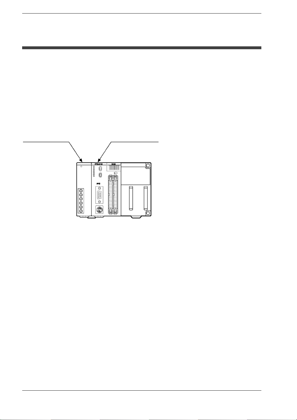
2.2.2 CPU with 64 Points Input (FP2−C1D) 2 − 12......................
i
Page 4

FP2/FP2SHTable of Contents
2.3 Expansion Memory Unit and ROM (for FP2 CPU) 2 − 15...................
2.4 FP2SH CPU 2 − 18...................................................
2.4.1 32k/60k Step Standard Type CPU (FP2-C2L/FP2-C2) 2 − 19........
2.4.2 CPU with IC Memory Card Interface (FP2-C2P/FP2−C3P) 2 − 20....
2.5 Expansion Memory Unit and ROM (for FP2−C2L/FP2-C2) 2 − 22............
2.6 IC Memory Card (for FP2-C2P/FP2-C3P) 2 − 23...........................
2.7 Power Supply Units 2 − 28.............................................
2.7.1 Power Supply Specifications 2 − 28..............................
2.8 Input and Output Units 2 − 30...........................................
2.8.1 Common Specifications of Input and Output Units 2 − 30............
2.9 Input Units Specifications 2 − 33........................................
2.9.1 16-point Type DC Input Unit 2 − 33...............................
2.9.2 32-point Type DC Input Unit 2 − 35...............................
2.9.3 64-point Type DC Input Unit 2 − 37...............................
2.10 Output Units Specifications 2 − 39.......................................
2.10.1 16-point Type Relay Output Unit 2 − 39...........................
2.10.2 6-point Type Relay Output Unit 2 − 41............................
2.10.3 16-point Type Transistor (NPN) Output Unit 2 − 43.................
2.10.4 16-point Type Transistor (PNP) Output Unit 2 − 45.................
2.10.5 32-point Type Transistor (NPN) Output Unit 2 − 47.................
2.10.6 32-point Type Transistor (PNP) Output Unit 2 − 49.................
2.10.7 64-point Type Transistor (NPN) Output Unit 2 − 51.................
2.10.8 64-point Type Transistor (PNP) Output Unit 2 − 53.................
2.11 I/O Mixed Units Specifications 2 − 55....................................
2.11.1 32−point Type DC Input/32−point Type Transistor (NPN)
Output Unit 2 − 55.............................................
2.11.2 32−point Type DC Input/32−point Type Transistor (PNP)
Output Unit 2 − 58.............................................
2.11.3 32−point Type DC Input with On Pulse Catch Input Function/
32−point Type Transistor Output (NPN) Unit 2 − 61.................
2.11.4 32−point Type DC Input with On Pulse Catch Input Function/
32−point Type Transistor Output (PNP) Unit 2 − 64.................
2.11.5 On Pulse Catch Input Function 2 − 67............................
Chapter 3 I/O Allocation
3.1 Fundamentals of I/O Allocation 3 − 3......................................
3.1.1 I/O Allocation and Registering 3 − 3...............................
3.1.1.1 Types of I/O Allocation Methods 3 − 3...................
3.1.1.2 Precautions Regarding Registering of I/O Allocation 3 − 3.
3.1.1.3 How to Count the I/O Numbers and Express the
Occupied Points 3 − 4................................
3.1.2 Table of Occupied I/O Points by Unit 3 − 5.........................
3.2 Arbitrary Allocation 3 − 7................................................
3.2.1 Using Arbitrary Allocation 3 − 7...................................
ii
Page 5

FP2/FP2SH
Table of Figures
3.2.2 Allocation Example of CPU Backplane 3 − 7.......................
3.2.3 Allocation Example of Expansion Backplane 3 − 10................
3.2.3.1 When Using FP2 Backplane 3 − 10....................
3.2.3.2 When Using FP2 Backplane H Type 3 − 11..............
3.3 I/O Mount Allocation 3 − 13.............................................
3.3.1 Using I/O Mount Allocation 3 − 13................................
3.3.1.1 Example of I/O Mount Allocation 3 − 13................
3.3.1.2 Procedure for I/O Mount Allocation 3 − 14..............
3.4 Automatic Allocation 3 − 15.............................................
3.4.1 Using Automatic Allocation 3 − 15...............................
3.4.1.1 Example of Automatic Allocation 3 − 15................
3.4.1.2 Procedure for Automatic Allocation 3 − 16..............
3.5 Procedure for Clearing Registered Content 3 − 17.........................
3.5.1 Meaning of Clearing Registered Content 3 − 17....................
3.5.2 Clearing Content Using Programming Tool Software 3 − 17.........
3.6 I/O Numbers of Free Slots 3 − 18........................................
3.6.1 I/O Numbers of Free Slots 3 − 18................................
3.6.2 Differences Due to Allocation Methods 3 − 18.....................
3.6.2.1 When Arbitrary Allocation is Used 3 − 18...............
3.6.2.2 When I/O Mount Allocation is Used 3 − 20..............
3.6.2.3 When Automatic Allocation is Used 3 − 21..............
Chapter 4 Installation and Wiring
4.1 Installation 4 − 3.......................................................
4.1.1 Installation Space and Environment 4 − 3..........................
4.1.2 Mounting Method 4 − 6..........................................
4.1.2.1 Backplane 4 − 6......................................
4.1.2.2 Units 4 − 8..........................................
4.1.3 Connecting Expansion Cable 4 − 11..............................
4.1.4 Preparing the Backup Battery 4 − 13.............................
4.2 Power Supply Wiring 4 − 15............................................
4.2.1 Wiring of Power Supply 4 − 15..................................
4.2.2 Grounding 4 − 17..............................................
4.3 Wiring Input and Output 4 − 18..........................................
4.3.1 Input Wiring 4 − 18.............................................
4.3.2 Output Wiring 4 − 21...........................................
4.3.3 Cautions Regarding Units 4 − 22................................
4.4 Wiring the Connector Type I/O Units 4 − 23...............................
4.4.1 Wiring the Connector Type Units 4 − 23..........................
4.4.2 Connecting with Connector for Wire-pressed Terminal Cable 4 − 25..
4.4.3 Connecting the Terminals 4 − 27.................................
4.4.4 Connecting with Flat Cable Connector 4 − 32......................
4.5 Wiring the Terminal Block Type I/O Units 4 − 34...........................
iii
Page 6

FP2/FP2SHTable of Contents
4.5.1 Wiring the Terminal Block Type Units 4 − 34.......................
4.6 Safety Measures 4 − 36................................................
4.6.1 Safety Instructions 4 − 36.......................................
4.6.2 Momentary Power Failures 4 − 37...............................
4.6.3 Alarm Output 4 − 37...........................................
Chapter 5 Procedure Until Operation
5.1 Before Turning ON the Power 5 − 3.......................................
5.1.1 Check Items 5 − 3..............................................
5.1.2 Procedure Up To Operation 5 − 4.................................
5.2 Programming with Programming Tool Software 5 − 5........................
5.2.1 Preparations 5 − 5..............................................
5.2.2 Configuration of Programming Tool Software 5 − 6..................
5.2.2.1 Parameters and Setting Methods 5 − 6..................
Chapter 6 FP2/FP2SH Operation
6.1 FP2 Operation 6 − 3....................................................
6.1.1 FP2 RAM and ROM Operations 6 − 3.............................
6.1.1.1 Comparison of RAM and ROM Operations 6 − 3..........
6.1.1.2 Retaining the Data During Power Outages 6 − 4..........
6.1.1.3 Setting the Battery Error Warnings 6 − 4.................
6.2 FP2 RAM Operation 6 − 5...............................................
6.2.1 RAM Operation Method 6 − 5....................................
6.2.2 Precautions When Operating the RAM 6 − 5.......................
6.3 FP2 ROM Operation 6 − 6...............................................
6.3.1 ROM Operation Method 6 − 6....................................
6.3.2 Verifying the ROM Contents in RAM Operation 6 − 7................
6.4 Writing to ROM 6 − 8...................................................
6.4.1 Writing to EPROM Using Programming Tool Software 6 − 8..........
6.4.2 Writing to EPROM via FROM 6 − 10.............................
6.5 FP2SH Operation 6 − 13...............................................
6.5.1 Comparison of RAM, ROM, and IC Memory Card Operation 6 − 13...
6.5.2 Retaining Data If the Power Fails 6 − 14..........................
6.5.3 Comment Function 6 − 16......................................
6.6 FP2SH RAM Operation 6 − 17..........................................
6.6.1 RAM Operation Method 6 − 17..................................
6.6.2 Precautions When Operating the RAM 6 − 18.....................
6.7 FP2SH ROM Operation 6 − 19..........................................
iv
Page 7

FP2/FP2SH
6.7.1 ROM Operation Function 6 − 19.................................
6.7.2 ROM Operation Method 6 − 20..................................
6.7.3 Precautions When Operating the ROM 6 − 21.....................
6.7.4 Checking the ROM Contents While Using RAM Operation 6 − 22....
6.7.5 Sending Data from the RAM to the FROM 6 − 23..................
6.7.6 Writing Data to the ROM (AFP5209) (only the FP2−C2
can be installed) 6 − 25.........................................
6.7.7 Writing Data to the ROM: Using the FPWIN GR 6 − 27.............
6.8 FP2SH IC Memory Card Operation (for FP2−C2P/FP2−C3P) 6 − 29.........
6.8.1 Operating Using the IC Memory Card 6 − 29......................
6.8.2 Creating Files for Automatically Run Programs 6 − 31..............
6.8.3 How the IC Memory Card is Operated 6 − 32......................
6.8.4 Transferring Data From the RAM to the IC Memory Card 6 − 33......
Table of Figures
Chapter 7 IC Memory Card
7.1 Using the IC Memory Card 7 − 3.........................................
7.1.1 Types of IC Memory Cards 7 − 3.................................
7.1.2 Using the IC Memory Card 7 − 4..................................
7.2 Formatting and Erasing 7 − 6............................................
7.2.1 Program Memory Field and Expanded Memory Field 7 − 6...........
7.2.2 Procedure for Formatting the IC Memory Card 7 − 8.................
7.2.3 Procedure for Erasing the IC Memory Card 7 − 11..................
7.2.4 Data Storage Capacity of IC Memory Card 7 − 12..................
7.3 For Use as Program Memory 7 − 13.....................................
7.3.1 Writing the Program 7 − 13.....................................
7.3.2 Reading the Program 7 − 18....................................
7.4 For Use as Expansion Memory 7 − 22....................................
7.5 Menus Related to Tool Software 7 − 25...................................
Chapter 8 Self-Diagnostic Function and Troubleshooting
8.1 Self-Diagnostic Function 8 − 3...........................................
8.1.1 LED Display for Status Condition 8 − 3............................
8.1.2 Operation When an Error Occurs 8 − 4............................
8.2 Troubleshooting 8 − 5...................................................
8.2.1 If the ERROR LED Lights 8 − 5...................................
8.2.2 If the ALARM LED Lights 8 − 7...................................
8.2.3 If the LED (POWER) of the Power Supply Unit Does Not Light 8 − 7...
v
Page 8

FP2/FP2SHTable of Contents
8.2.4 If Outputting Does Not Occur as Desired 8 − 8.....................
8.2.5 If a Communication Error Message Appears 8 − 9..................
8.2.6 If a Protect Error Message Appears 8 − 10........................
Chapter 9 Maintenance
9.1 Replacement of Spare Parts 9 − 3........................................
9.1.1 Backup Battery 9 − 3............................................
9.1.2 Removable Terminal Block for Input and Output Units 9 − 7..........
9.2 Preventive Maintenance 9 − 8...........................................
Chapter 10 Specifications
10.1 Specifications 10 − 3...................................................
10.2 Relays, Memory Areas and Constants 10 − 10............................
10.3 Cable/Adapter Specifications 10 − 13....................................
10.3.1 AFC8503/AFC8503S 10 − 13...................................
10.3.2 AFC85305/AFC8531/AFC8532
(For extending for the tool port) 10 − 13...........................
Chapter 11 Appendix
11.1 System Registers/Special Internal Relays/Special Data Registers 11 - 2......
11.1.1 Table of System Registers for FP2/FP2SH/FP10SH 11 − 4...........
11.1.2 Table of Special Internal Relays for FP2/FP2SH/FP10SH 11 − 18....
11.1.3 Special Data Registers for FP2/FP2SH/FP10SH/FP3 11 − 29........
11.2 Table of Basic Instructions 11 − 54.......................................
11.3 Table of High−level Instructions 11 − 62..................................
11.4 Table of Error codes 11 − 82............................................
11.4.1 Table of Syntax Check Error 11 − 84.............................
11.4.2 Table of Self−Diagnostic Error 11 − 86............................
11.4.3 Table of MEWTOCOL−COM Communication Error 11 − 93..........
11.5 MEWTOCOL−COM Communication Commands 11 − 95...................
11.6 Hexadecimal/Binary/BCD 11 − 96.......................................
11.7 ASCII Codes 11 − 97..................................................
Index I − 1......................................................................
Record of changes R − 1...................................................
vi
Page 9

FP2/FP2SH
Table of Figures
Before You Start
Operating environment
(Use the unit within the range of the general specifications when installing)
• Ambient temperatures:0 to +55 °C
• Ambient humidity: 30% to 85% RH (at 25 °C, non−condensing)
• For use in pollution Degree 2 environment.
• Do not use it in the following environments.
− Direct sunlight
− Sudden temperature changes causing condensation.
− Inflammable or corrosive gas.
− Excessive airborne dust, metal particles or saline matter.
− Benzine, paint thinner, alcohol or other organic solvents or
strong alkaline solutions such as ammonia or caustic soda.
− Direct vibration, shock or direct drop of water.
− Influence from power transmission lines, high voltage
equipment, power cables, power equipment, radio transmitters,or
any other equipment that would generate high switching surges.
(100mm or more)
About static electricity
• Do not touch connector pins directly to prevent static electricity
from causing damage.
• Always rid yourself of any static electricity before handling this
product.
Wiring the Power Supply to the Control Unit
• Use a power supply wire that is thicker than 2 mm2(AWG14), and
twist it.
• The unit has sufficient noise immunity against the noise generated
on the power line.
However, it is recommended to take measures for reducing noise
such as using a isolating transformer before supplying the power.
• Allocate an independent wiring for each power supplying line,
input/output device and operating device.
If using a power supply without a protective circuit, power should
be supplied through a protective element such as a fuse.
• Use the same power supply system for the CPU backplane and
expansion backplane so that they are turned on and off
simultaneously.
vii
Page 10

FP2/FP2SHTable of Contents
Power supply sequence
• In order to protect the power supply sequence, make sure to turn
off the PLC before the input/output power supply. If the input/output
power supply is turned off before the PLC, or if the PLC is not shut
off momentarily, the controller detects change of input level, and
might conduct an unexpected operation.
Before Turning On the Power ( Chapter 4 and Chapter 5)
When turning on the power for the first time, be sure to take the precautions given below.
• When performing installation, check to make sure that there are no
scraps of wiring, particularly conductive fragments, adhering to the
unit.
• Verify that the power supply wiring, I/O wiring, and power supply
voltage are all correct.
• Sufficiently tighten the installation screws and terminal screws.
• Set the mode selector to PROG. mode.
Before Entering a Program ( Chapter 5)
Be sure to perform a program clear operation before entering a program.
When using FPWIN GR software
Procedure:
1. Execute “FPWIN GR”.
2. ON the “Online” menu, select “Online Edit Mode”.
3. ON the “Edit” menu, select “Clear Program”.
Battery
Do not install the battery when it is not used.
There is a possibility of leak if the battery remains discharged.
viii
Page 11
FP2/FP2SH
Table of Figures
Special Precautions
With the FP2
The FP2 uses the term “module” when express the size of the unit or backplane.
The unit installation sizes come in two sizes: the basic 1-module size, and the 2-module
size that is twice as wide.
The 1-module unit is the size that physically takes up the space of one guide on the
backplane.
The 2-module unit is the size that physically takes up the space of two guides on the
backplane.
1-module unit 2-module unit
Backplane Selection
Following two kinds of backplanes are available.
1) FP2 backplane (AFP25***) (Color of letters on the printed board: White)
2) FP2 backplane H type (AFP25****H) (Color of letters on the printed board: Yellow)
These two backplanes cannot be used in combination.
Carefully select the type of backplanes before you order.
The selection of the backplane should be based on the total number of modules to be
used in the system. In other words, the module number of the backplane must be
greater than or equal to the total number of modules for the system. So be sure to select
a backplane that allows the installation of all the required units.
ix
Page 12

FP2/FP2SHTable of Contents
When using the FP3, FP10SH, or Other Units
Backplane slot number
The backplane for the FP2 is specified by the total number of slots, i.e., 14-module type,
including the connectors for the power supply unit and CPU. The number of connectors
(or slots) remaining for the I/O units and intelligent units is then the module number of
the backplane minus the number of modules for the power supply unit and CPU.
Similarly, the number of connectors (or slots) remaining for the I/O units on expansion
backplanes is the module number of the backplane minus the number of modules for
the power supply unit.
Expansion backplanes
1. FP2 backplane
− Does not support expansion with 5-module type backplanes.
− Backplanes that are not the 5-module type can be used as expansion backplanes.
2. FP2 backplane H type
− This backplane is functionally equivalent to the backplane for FP3.
− There are the basic backplane H type for installing I/O units and the expansion
backplane H type for adding I/O units more.
− The basic backplane cannot be used as an expansion backplane.
Removal and Installation of Expansion Memory Unit
During removal and installation of expansion memory unit, the contents of the internal
RAM may be erased, so be sure to save a copy of the program and data onto a disk
before beginning the operations.
Use programming tool software (NPST−GR/FPWIN GR) for backup purposes.
Before rewriting the backed up program and data to the programmable controller, be
sure to clear the program in the programmable controller.
x
Page 13

FP2/FP2SH
Table of Figures
With the FP2SH
Programming Tool Restrictions
The following tool software is required in order to program the FP2SH.
“FPWIN GR”
“NPST−GR” Ver. 4.6 or a subsequent version
Request Concerning Program Storage
To prevent the accidental loss of programs, the user should consider the following
measures.
Drafting of documents
To avoid accidentally losing programs, destroying files, or overwriting the contents of
a file, documents should be printed out and then saved. Disks should be organized to
assure safe maintenance.
Specifying the password carefully
The password setting is designed to avoid programs being accidentally overwritten. If
the password is forgotten, however, it will be impossible to overwrite the program even
if you want to. Also, if a password is forcibly bypassed, the program is deleted. When
specifying the password, note it in the specifications manual or in another safe location
in case it is forgotten at some point.
Saving programs to the ROM
In order to prevent programs from being lost if the backup battery runs down, and to
prevent accidental overwriting of programs in the workplace, we recommend saving
programs entered in the RAM to the ROM. If the PLC is used over a long period of time,
this concern applies particularly to programs that are built into the device when shipped.
Check the manuals for specifications and other items pertaining to usage.
FP series Programming Manual
xi
Page 14
FP2/FP2SHTable of Contents
p
y
Memor
y
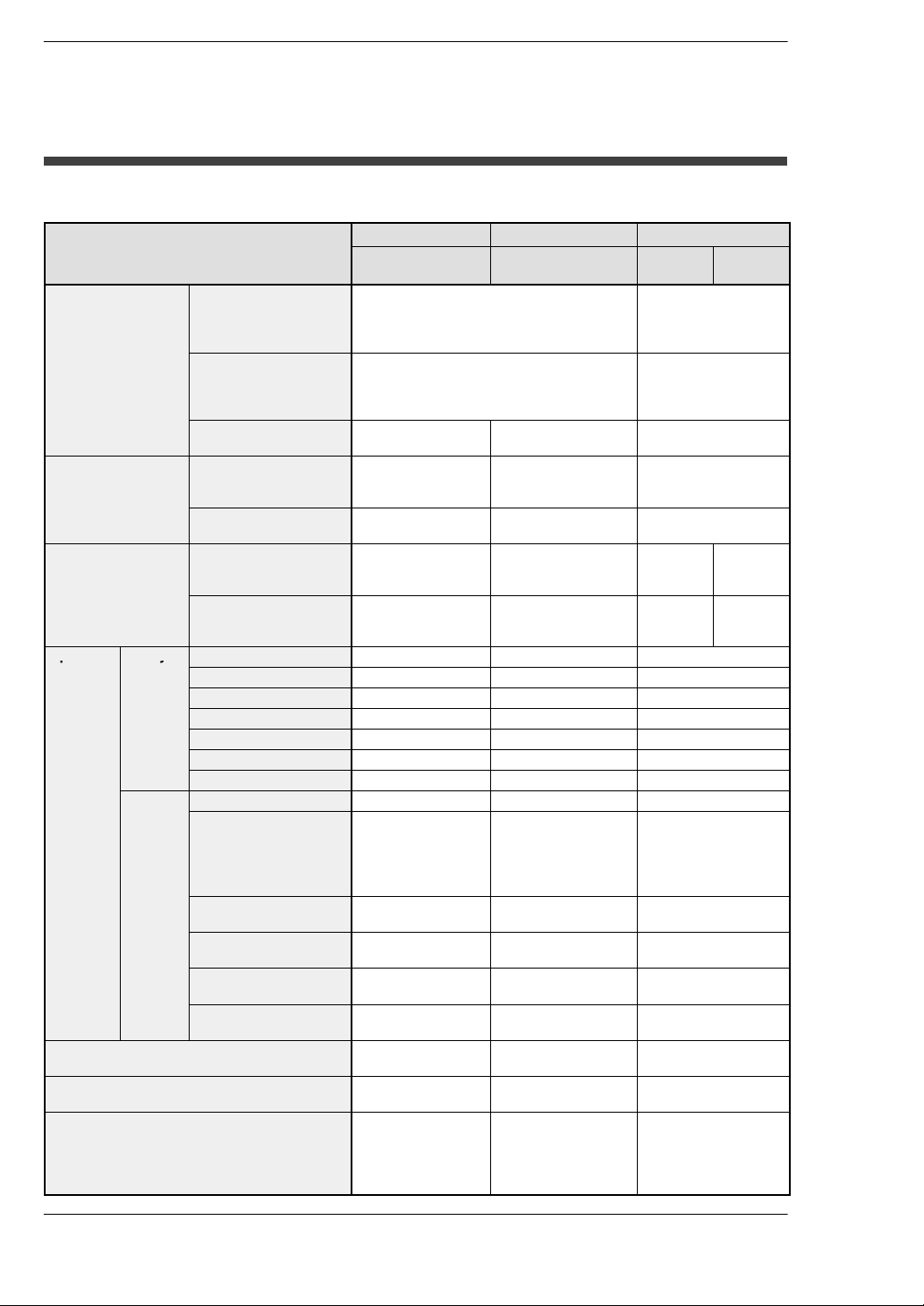
Compatibility with CPU unit, and Precautions
Comparison of Specifications
Items
Controllable I/O
points
Program capacity
Operation speed
(typical value)
Operation Relays
memory
points
Memory
areas
Comment input function Optional function Built−in (Internal)
Clock/calendar function Optional function Built−in (Internal)
ROM operation function Optional function FP2−C2L, FP2−C2:
Basic construction Using Backplanes: Max. 768 points (12
Expanded
construction
Using remote I/O
system
Internal memory Approx. 16k steps Approx. 60k steps
Using expansion
memory
Basic instructions From 0.35µs per
High-level instructions From 0.93µs per
External input (X) 2,048 points 8,192 points 8,192 points
External output (Y) 2,048 points 8,192 points 8,192 points
Internal relays (R) 4,048 points 14,192 points 14,192 points
Timer/counter (T/C) Total 1,024 points Total 3,072 points Total 3,072 points
Link relays (L) 2,048 points 10,240 points 10,240 points
Pulse relays (P) 1,024 points 2,048 points 2,048 points
Alarm relays (E) None 2,048 points 2,048 points
Data registers (DT) 6,000 words 10,240 words 10,240 words
File registers (FL) 0 to 14,333 words
Link data registers
(LD)
Timer/counter set
value area (SV)
Timer/counter elapsed
value area (EV))
Index registers
(I0 to ID)
FP2 CPU FP2SH CPU FP10SH CPU
FP2−C1, FP2−C1D,
FP2−C1A,FP2−C1SL
modules)
Using Backplanes H type: Max. 512 points
(8 modules)
Using Backplanes: Max. 1,600 points (25
modules)
Using Backplanes H type: Max. 2,048
points (32 modules)
Max. 2,048 points Max. 8,192 points Max. 8,192 points
Approx. 32k steps — Approx. 60k steps/
instruction
instruction
(when expanding: 0
to 30,717 words)
256 words 8,448 words 8,448 words
1,024 words 3,072 words 3,072 words
1,024 words 3,072 words 3,072 words
14 words 14 words×16 banks 14 words×16 banks
FP2−C2L, FP2−C2,
FP2−C2P,FP2−C3P
(For FP2−C3P,
approx. 120k steps)
From 0.03µs per
instruction
From 0.06µs per
instruction
FP2−C2L: 32,765
words
FP2−C2, FP2−C2P,
FP2−C3P: 32,765
words × 3 banks
function
function
Optional function
FP2−C2P, FP2−C3P:
Built−in (Internal)
function
AFP
6221V3
Max. 512 points
Max. 2,048 points
Approx. 30k steps
120k steps
From
0.04µs per
instruction
From
0.08µs per
instruction
32,765 words
Optional function
Built−in (Internal)
function
Optional function
AFP
6211V3
From
0.10µs per
instruction
From
0.20µs per
instruction
xii
Page 15

FP2/FP2SH
Table of Figures
Compatibility of FP2SH and FP2, and Precautions
Hardware Compatibility
Most of the units and related products used with the FP2SH can be used with the FP2,
but the following differences should be noted.
Some optional memory units cannot be used.
The only memory unit that can be used with the FP2SH CPU FP2−C2 or FP2−C2L” is
the ”Part number FP2−EM7 or Model number AFP2208”.
The FP2 memory units “Part numbers FP2−EM1, FP2−EM2, FP2−EM3, and
FP2−EM6” cannot be used.
The types of optional ROMs are different.
The only ROM that can be used with the FP2SH CPU unit ”FP2−C2” is the ”Model
number AFP5208 or AFP5209”. The nonvolatile memory implemented memory unit
”Model number AFP2208” can be also used.
The FP2 ROM “Part number AFP2204” and “Part number AFP2205” cannot be used.
The backup battery types are different.
The backup battery for the FP2SH CPU is the “Part number AFP8801” battery with a
connector.
The “Part number AFC8801” battery for the FP2 CPU cannot be used.
The calendar timer and comment memories have been installed in advance.
These have already been installed in the FP2SH CPU, and no optional units are
needed.
ROM operation functions in the FP2SH
CPUs that support IC memory cards (FP2−C2P and FP2−C3P) have an internal FROM
used as a program memory. The internal FROM cannot be replaced.
Software Compatibility
The FP2SH has a higher level of compatibility than the FP2, so there are no functions
that cannot be used with the FP2SH. Other factors, such as the number of device
points, should be confirmed by checking the specifications comparison table on the
previous page.
xiii
Page 16

FP2/FP2SHTable of Contents
IC memory cards for the FP2SH
The existing model number becomes the one to be discontinued because of the
termination of manufacturing IC memory cards by the parts manufacturer. When placing
a new order, specify the new product number.
Termination of Production
Type Memory capacity Model No. Battery type
SRAM
New product
Type Memory capacity Model No. Battery type
SRAM
Notes
2MB AIC52000 Internal secondary battery (Rechargeable type)
2MB AFP2209 Lithium Battery (Interchangeable type)
For AFP2209
• An interchangeable lithium battery is used. When you use for
the first time, install the battery included.
For AIC52000
• Memory backup of the SRAM type of IC memory card
(AIC52000) Is handled by an internal secondary battery. When
the battery is used for the first time, power must be supplied
for at least 24 hours to charge it fully. When the battery is fully
charged, data is backed up for more than three months with
out the power being turned on. Normally, the card should be
installed in the PLC and power supplied when using it. Failing
to charge the battery periodically can reduce the backup
period and the service life of the battery. The backup battery
cannot be replaced.
xiv
Page 17

FP2/FP2SH
Table of Figures
Compatibility of FP2/FP2SH and FP10SH, and Precautions
Hardware Compatibility
The unit, backplane, and other components are not compatible.
The components for the FP2 are used with the FP2SH.
When using the FP2 backplane (AFP25**), the maximum number of expansion
points is lower.
With the FP10SH and FP2 backplane H type (AFP25**H), up to three expansion boards
can be used, and a maximum of 2048 points controlled, but if using the FP2 backplane
with the FP2/FP2SH, only one expansion board can be used, and a maximum of 1600
points controlled.
Different types of IC memory cards are used.
The only type of IC card that can be used with the “Part number FP2−C2P and
FP2−C3P” FP2SH CPU is the IC memory card (small PC card). The IC memory card
for the FP10SH cannot be used.
Software Compatibility
With the FP2SH, in comparison with the FP10SH, there are no functions that cannot
be used. For other detailed specifications, check the specifications comparison table
on the previous page.
xv
Page 18

FP2/FP2SHTable of Contents
yp
pg g
Programming Tool Restrictions
Restrictions on usable programming tools depending on the units
Type of programming tool
Windows software
Windows software
Conforms to
IEC61131−3
Handy programming
unit
FP Memory Loader
FP2 FP2SH
FPWIN GR Ver.2 Used
FPWIN GR Ver.1 Used
FPWIN Pro Ver.6 Used Used
FPWIN Pro Ver.5 Used
AFP1113V2
AFP1114V2
AFP1113
AFP1114
AFP1111A
AFP1112A
AFP1111
AFP1112
AFP8670
AFP8671
Note 1)
Note 1)
Note 3)
Not used Not used
Not used Not used
Not used Not used
Used Used
Type of unit
Used
Note 1)
Used
Note 1)
Note 2)
Used
Note 3)
Note 4)
Note 1) FPWIN GR Ver.2.91 or later version is necessary to use the FP2SH CPU (32k type).
FPWIN GR Ver.2.40 or later version is necessary to use the multi communication unit.
FPWIN GR Ver.2.71 or later version is necessary to use the MEWNET−VE Link Unit.
The FNS Unit and FMU Unit cannot use to FPWIN GR.
Note 2) FPWIN Pro Ver.6.3 or later version is necessary to use the FP2SH CPU (32k type).
Note 3) FPWIN Pro Ver.5.02 or later version is necessary to use the multi communication unit.
−FPWIN Pro Ver.5.24 or later version is necessary to use the MEWNET−VE Link Unit.
−FPWIN Pro Ver.5.24 or later version is necessary to use the FNS Unit.
−FPWIN Pro Ver.5.3 or later version is necessary to use the FMU Unit.
Note 4) FP Memory Loader Ver.2.1 or later version is necessary to use the FP2SH CPU (32k
type). When using FP2SH CPU (120k type), only the 1st program and comments can
be transferred.
Note: Precautions concerning version upgrade
• In case of using FPWIN GR Ver.1, please purchase upgrade model
FPWIN GR Ver.2.
• FPWIN GR Ver. 2.0 can be upgraded to Ver. 2.1 or later free of
charge at our web site.
• FPWIN Pro Ver. 6.0 can be upgraded to Ver. 6.1 or later free of
charge at our web site
(http://industrial.panasonic.com/ac/e/dl_center/software/).
xvi
Page 19

Chapter 1
Overview
Page 20

FP2/FP2SHOverview
1 − 2
Page 21
OverviewFP2/FP2SH
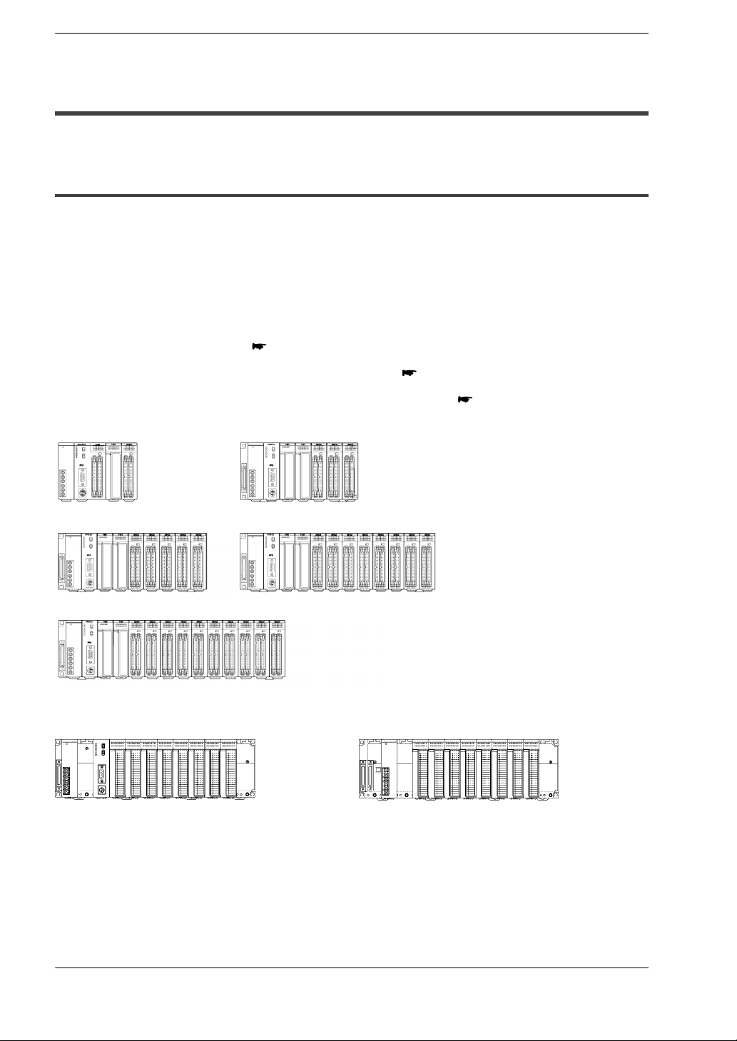
1.1 System Configuration
1.1 System Configuration
1.1.1 Basic Configuration by Number of Slots
The building block scheme allows you to combine units as desired.
Five types of backplanes and Two types of backplanes H types are available for the
FP2/FP2SH. A variety of input/output units can be installed as desired on the backplane.
Although most of the I/O units and intelligent units can be combined freely in the layout,
you should check the following three points when selecting your units:
− Restrictions on unit types
− Limitations on the internal current consumption
section 1.2.2.1
section 1.2.2.2
− Limitations on the number of modules of the backplane
FP2 backplane
5 modules 7 modules
9 modules 12 modules
14 modules
FP2 backplane H type
page 1 − 4
Basic backplane (11 modules) Expansion backplane (10 modules)
Following two kinds of backplanes are available.
1) FP2 backplane (AFP25***)
2) FP2 backplane H type (AFP25****H)
These two backplanes cannot be used in combination.
Carefully select the type of backplanes before you order.
1 − 3
Page 22
FP2/FP2SHOverview
1.1 System Configuration
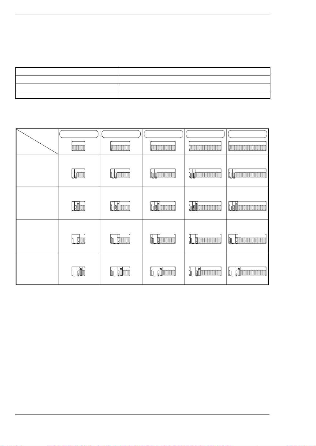
Restriction on the number of modules of the backplane (For master backplane)
The number of units that can be installed is determined by the number of modules of
the backplane used, the power supply unit to be installed, and the CPU.
1 module type CPU Standard type CPU
2 modules type CPU CPU with 64-point input, CPU with S-LINK
1 module type power supply unit 100V 2.5A, 200V 2.5A
2 modules type power supply unit 100 to 240V 5A, 24V DC 5A
CPU backplane
FP2 backplane
5-module type 7-module type 9-module type 12-module type 14-module type
1 module type
CPU and
1 module type
power supply
unit
2 modules type
CPU and
1 module type
power supply
unit
1 module type
CPU and
2 module type
power supply
unit
2 modules type
CPU and
2 module type
power supply
unit
3 slots free 5 slots free 7 slots free 10 slots free 12 slots free
2 slots free 4 slots free 6 slots free 9 slots free 11 slots free
2 slots free 4 slots free 6 slots free 9 slots free 11 slots free
1 slot free 3 slots free 5 slots free 8 slots free 10 slots free
* slots free: Number of slots where units can be installed
1 − 4
Page 23
FP2 backplane H type
11−module type
OverviewFP2/FP2SH
1.1 System Configuration
1 module type
CPU and
1 module type
power supply
unit
2 module type
CPU and
1 module type
power supply
unit
1 module type
CPU and
2 module type
power supply
unit
2 module type
CPU and
2 module type
power supply
unit
8 slots free
7 slots free
8 slots free
7 slots free
A maximum of eight I/O units (including the unit built in the CPU)
can be controlled per backplane. Even if further I/O units are
installed, they are not recognized.
Note) When using the CPU unit with S−LINK, seven slots are free,
however, the units actually usable are only six. (Refer to Chapter 3
I/O Allocation.)
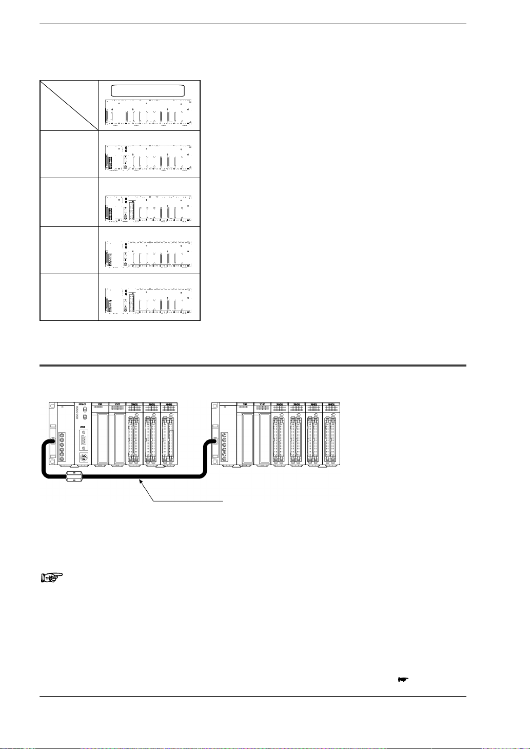
1.1.2 Expansion of Backplane
FP2 backplane
CPU backplane Expansion backplane
Expansion cable
Only one backplane can be added-on for expansion.
Expansion is simply connecting a new backplane with a special expansion cable. Any
backplane other than a 5-module type can be used for expansion.
Notes
• A 5-module type backplane cannot be expanded.
• A 5-module type backplane cannot be added on for expansion.
• Only one backplane can be added-on for expansion.
• A power supply unit is also necessary on an expansion back-
plane.
next page
1 − 5
Page 24
1.1 System Configuration
• Do not install a CPU on an expansion backplane.
• There is no need to make the number of modules on the ex-
pansion backplane equal to the number of modules on the
CPU backplane.
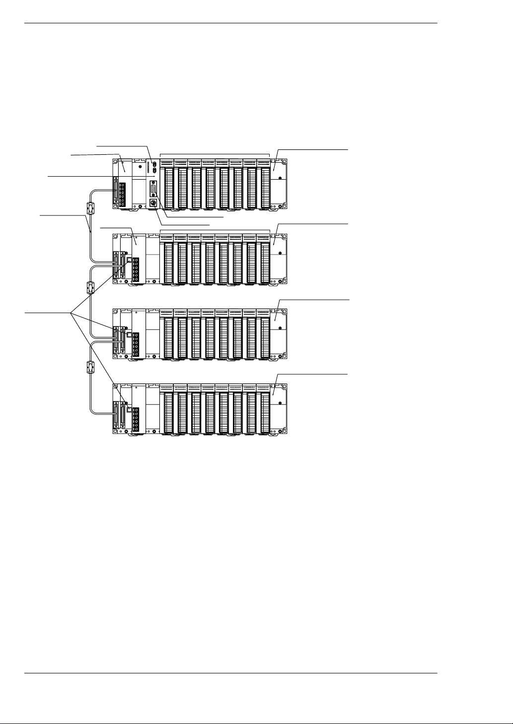
FP2 backplane H type
CPU unit
Power supply unit
Backup battery
Expansion memory
I/O unit
FP2/FP2SHOverview
Basic backplane
Expansion cable
Board No. setting
switches
Power supply unit
COM port
Tool port
I/O unit
Expansion backplane 1
Expansion backplane 2
Expansion backplane 3
The basic FP2 backplane H type that the CPU unit can be installed and the expansion
backplane H type that only the I/O units and the intelligent I/O units can be installed are
available.
A maximum of eight I/O units (including the unit built in the CPU) can be controlled per
backplane. Even if further I/O units are installed, they are not recognized.
Up to three expansion backplanes can be added on for expansion.
Use the board No. setting switches on the board to distinguish the expansion backplane.
A power supply unit is also necessary on an expansion backplane.
1 − 6
Page 25
OverviewFP2/FP2SH
1.1 System Configuration
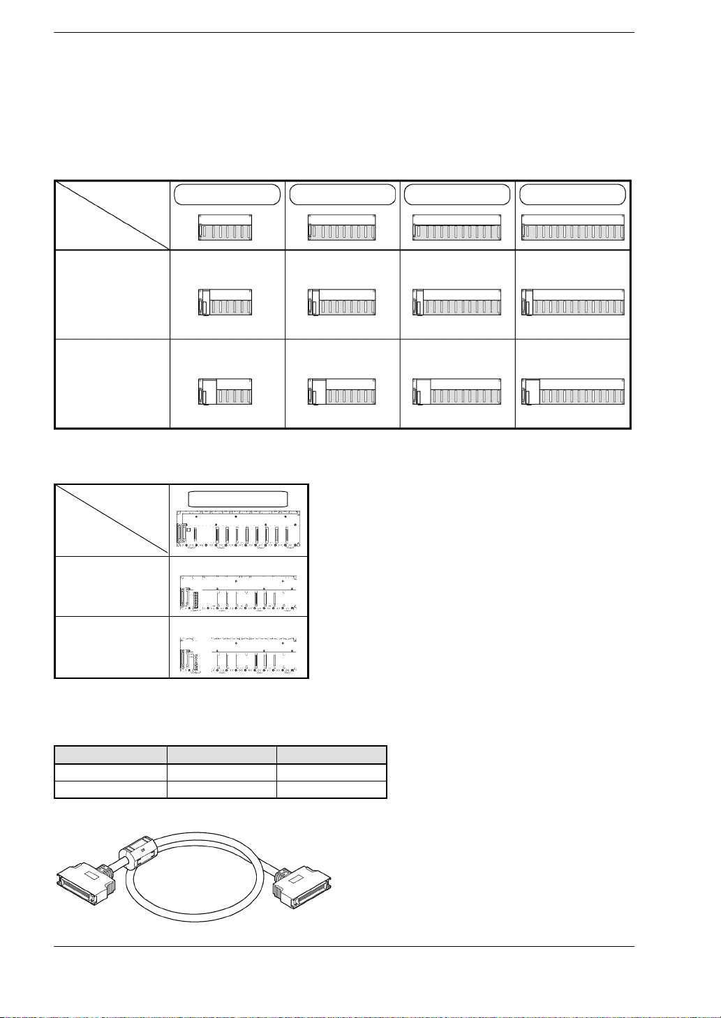
Restriction on the number of modules of the backplane (For expansion backplane)
The number of units that can be installed is determined by the number of modules of
the backplane used and the power supply unit to be installed.
FP2 backplane
7-module type 9-module type 12-module type 14-module type
1 module type
power supply
unit
2 module type
power supply
unit
6 slots free 8 slots free 11 slots free 13 slots free
5 slots free 7 slots free 10 slots free 12 slots free
* slots free: Number of slots where units can be installed
FP2 backplane H type
10-module type
1 module type
power supply
unit
2 module type
power supply
unit
8 slots free
8 slots free
Note) Although the connectors for installing I/O units are free with a 1−module type power supply unit, they cannot be used.
Expansion cable
Order number Length Ferrite core
FP2−EC 60 cm 1
FP2−EC2 2m 2
Note) With the backplalne H type, the total cable length can be arranged within 3.2 m.
1 − 7
Page 26
1.2 Unit Types and Combinations
atte y
1.2 Unit Types and Combinations
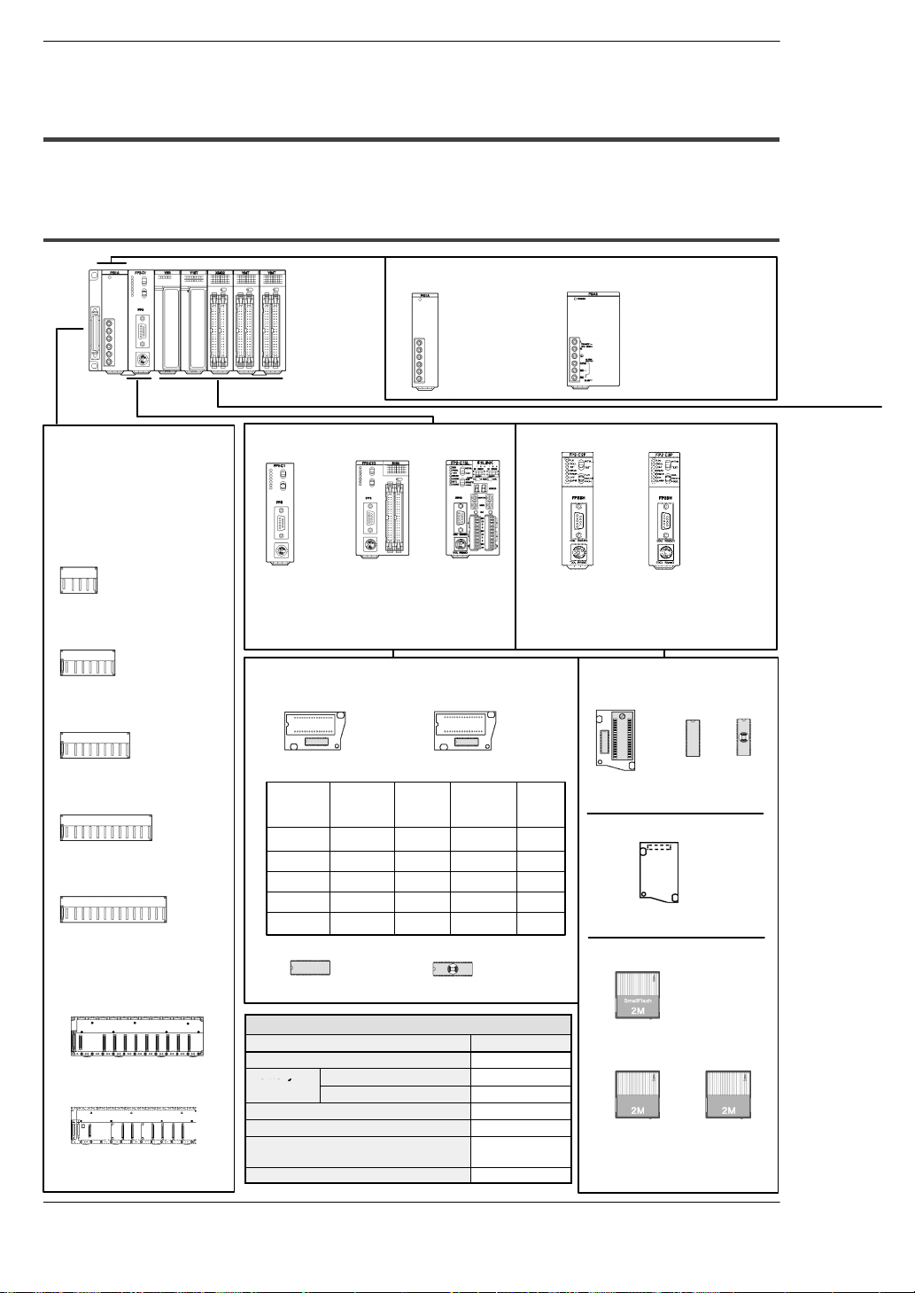
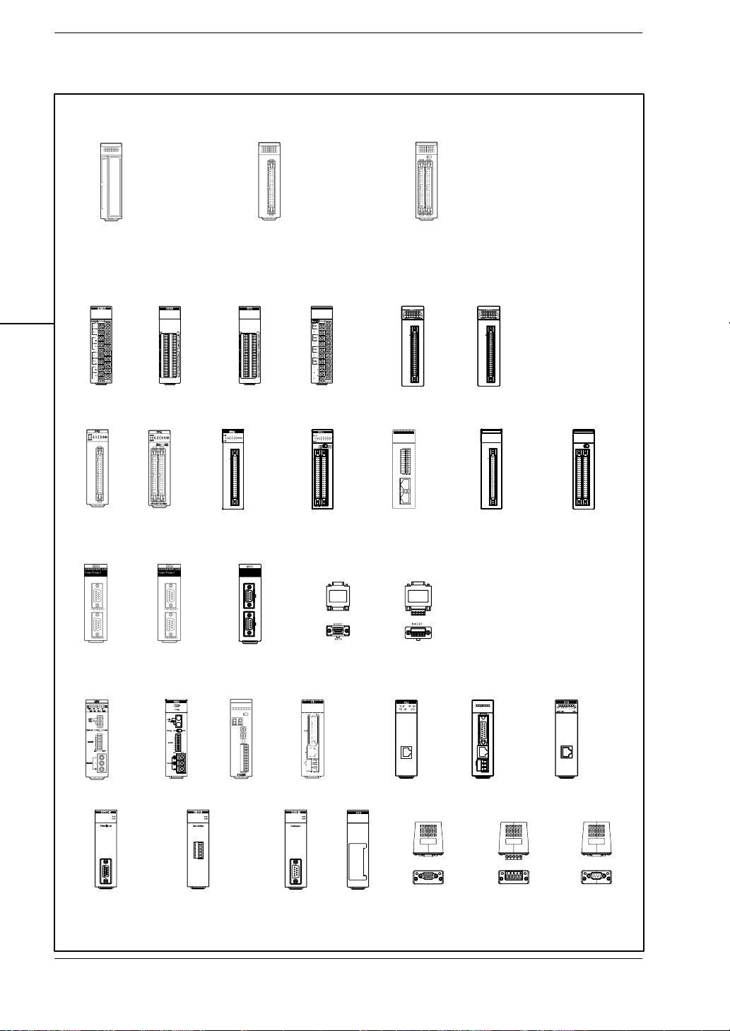
1.2.1 Line-Up of Backplanes and Units
Power supply units
FP2/FP2SHOverview
Backplanes
(for CPU and expansion backplanes)
The 5−module type
backplane can not be
used for expansion.
5-module type
(FP2−BP05)
7-module type
(FP2−BP07)
9-module type
(FP2−BP09)
12-module type
(FP2−BP12)
14-module type
(FP2−BP14)
Backplanes H type
11-module type (Basic)
FP2−BP11MH (AFP25011MH)
10-module type (Expansion)
FP2−BP10EH (AFP25010EH)
100V AC 2.5A type
(FP2−PSA1)
200V AC 2.5A type
(FP2−PSA2)
FP2 CPU FP2SH CPU
Standard type
CPU
(FP2−C1)
Optional memories
CPU with
64-point input
(FP2−C1D)
CPU with
S-LINK
(FP2−C1SL)
Standard type:
32k step: FP2−C2L
(AFP2221)
60k step: FP2−C2
(AFP2231)
Memory unit for FP2SH
For FP2
FP2−EM1
FP2−EM2
FP2−EM3
FP2−EM6
FP2−EM7
Type of memory unit
Part No. Comment
input
function
FP2−EM1
FP2−EM2
FP2−EM3
FP2−EM6
FP2−EM7
N/A
N/A
Clock/
calendar
function
A
A
A
A
A
A
N/A
N/A
With 16k
expansion
RAM
N/A
A
A
A
N/A
ROM
socket
N/A
N/A
A: Available, N/A: Not available
FROM FP2−EM4
EPROM FP2−EM5
Option
Product name Product number
Dummy unit AFP2300
Battery Lithium battery (button) AFC8801
Battery for AFP2209 AFP2806
Terminal block for FP2 I/O unit AFP2800
Set of connector for wire−pressed
terminal cable (2 pieces)
Set of flat cable connector (2 pieces) AFP2802
Lithium battery AFP8801
AFP2801
Memory unit
ROM socket
(FP2-EM7)
Memory unit for FP2SH
A
A
A
Memory unit F−ROM implemented)
(AFP2208)
Small PC card for FP2SH
FROM type IC memory card
(AIC50020)
100 to 240V AC 5A type
(FP2−PSA3)
24V DC 5A type
(FP2−PSD2)
Small PC card compliant type:
60k step: FP2−C2P
(AFP2235)
120k step: FP2−C3P
(AFP2255)
F−ROM
(AFP5208)
SmallS-
RAM
SRAM type IC
memory card
(AIC52000)
Discontinued
products
SRAM type IC
memory card
(AFP2209)
EP−ROM
(AFP5209)
SmallS-
RAM
1 − 8
Page 27
Input, Output and I/O mixed units
OverviewFP2/FP2SH
1.2 Unit Types and Combinations
Analog input
FP2−AD8VI
Positioning
(2−axis)
FP2−PP2
16-point DC input
(FP2−X16D2)
16-point transistor output
NPN type (FP2−Y16T)
16-point transistor output
PNP type (FP2−Y16P)
6-point relay output type
(FP2−Y6R)
16-point relay output type
(FP2−Y16R)
Analog output
FP2−AD8X
Positioning
(4−axis)
FP2−PP4
Positioning (2−axis)
Multifunction
Transistor FP2−PP21
Line driver FP2−PP22
RTD input
FP2−RTD
32-point DC input
(FP2−X32D2)
32-point transistor output NPN type
(FP2−Y32T)
32-point transistor output PNP type
(FP2−Y32P)
DA4
Analog output
FP2−DA4
Positioning (4−axis)
Multifunction
Transistor FP2−PP41
Line driver FP2−PP42
High speed counter
FP2−HSCT(NPN)
FP2−HSCP(PNP)
Positioning RTEX
FP2−PN2AN
(2−axis)
FP2−PN4AN
(4−axis)
FP2−PN8AN
(8−axis)
64-point DC input (FP2−X64D2)
64-point transistor output NPN type
(FP2−Y64T)
64-point transistor output PNP type
(FP2−Y64P)
32-point input/ 32-point output
NPN type (FP2−XY64D2T)
32-point input/output (NPN) with on
pulse catch input (FP2−XY64D7T)
32-point input/ 32-point output
PNP type (FP2−XY64D2P)
32-point input/output (PNP) with on
pulse catch input (FP2−XY64D7P)
Pulse I/O
FP2−PXYT(NPN)
FP2−PXYP(PNP)
Positioning (2−axis)
(Interpolation)
Transistor FP2−PP2T
Line driver
FP2−PP2L
Positioning (4−axis)
(Interpolation)
Transistor FP2−PP4T
Line driver FP2−PP4L
Serial data
FP2−SDU
Multi−wire link
FP2−MW
FMU
FP2−DPV1−M
C.C.U
FP2−CCU
Remote I/O Slave
FP2−RMS
FP2−DEV−M
FMU
MCU
FP2−MCU
S-LINK
FP2−SL2
MEWNET−VE link
FP2−VE
FMU
FP2−CAN−M
Communication
Block
FP2−CB232
FP2−CB422
FNS
FP2−FNS
Communication
Block
FP2−CB485
MEWNET−VE2 link
FP2−VE2
Communication
Block
PROFIBUS
(AFPN−AB6200)
ET−LAN
FP2−ET1
Communication
Block
DeviceNet
(AFPN−AB6201)
ET−LAN2
FP2−ET2
Communication
Block
CANopen
(AFPN−AB6218)
1 − 9
Page 28
1.2 Unit Types and Combinations
d
ppy
Sl
i
e
n
Canbeinstalled
within5unitsincombination
(MEWNET W
mode)
(PC
(PLC)
link
mode)
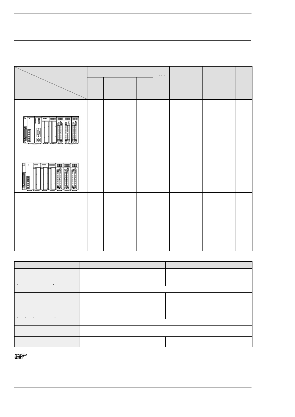
1.2.2 Combinations That Can be Used and Restrictions
1.2.2.1 Restrictions on Unit Types
FP2/FP2SHOverview
Backplanes and
units use
System
configuration
CPU backplane
Install in order from the left to the right, the
power supply unit, the CPU unit, the I/O and
the intelligent units.
Expansion backplane
Install in order from the left to the right, the
power supply unit, the I/O and the intelligent
units.
system backplan
Master backplane for slave station
ave stat
system
Install in order from the left to the right,
the power supply unit, the Remote I/O
on
slave unit,the I/O and the intelligent
units.*Replace the CPU on the CPU
backplane with a remote I/O slave unit.
e
Expansion backplane for slave
station system
Install in order from the left to the right,
the power supply unit, the I/O and the
intelligent units.* Same as the installation of the expansion backplane.
Backplane Backplane
(5module
type)
A A A N/A A A N/A A A A
N/A A N/A
A A A N/A A N/A A A A A
A A A A A N/A N/A A A A
(7-, 9-,
12-, 14module
type)
Htype
Basic
(11−
module
type)
Expansion
(10−
module
type)
A
*4
Power
CPU
Re-
Input
supply
unit
unit I/O
A N/A N/A A A A
mote
slave
unit
unit
Output
unit
I/O
mixed
unit
Limitations on Combining Link Units
Unit type and mode When CPU unit is FP2 When CPU unit is FP2SH
Computer communication unit Only one unit (see note) Can be installed within 5 units in combination
Multi−wire Link unit
(MEWNET−W mode)
Can be installed within 3 units in combination
with W link, CCU and MCU (PC link mode).
Can be installed within 2 units in combination with MCU in PC (PLC) link mode.
Multi−wire Link unit
(MEWNET−W2 mode)
ET−LAN unit
Multi Communication unit
(PC (PLC) link mode)
Up to 3 units can be used.
Up to 2 units out of 3, when including PC
(PLC) link.
Can be installed within 3 units in combination
with W link, CCU and MCU.
Can be installed within 2 units in combination with W link unit in PC (PLC) link mode.
Multi Communication unit
(Computer link mode)
Up to 8 units can be used.
MEWNET−VE Link Unit Not Available Can be installed within 2 units in combination
with W link, CCU and MCU (PC link mode).
Up to 8 units can be used.
Up to 2 units out of 8, when including PC
(PLC) link.
Can be installed within 5 units in combination
with W link, CCU and MCU.
with Multi Communication Unit.
Note
Depending on the location of the connected ports and the commands used for communication, up to 3 units can be used. For
more details, refer to the Computer Communication Unit Manual.
1 − 10
Page 29

OverviewFP2/FP2SH
p
1.2 Unit Types and Combinations
I/O
mixed
unit
Analog
input
unit
A
Output
unit
A A
A A A A
A A
A A
N/AN/
N/AN/
Notes
Pulse
Posi-
Posi-
Posi-
Posi-
Serial
Com-
S−
Analog
output
unit
A
A
A
High
−
spe
ed
cou
nter
unit
A*1A
A
*1
*5
A*6A
A*6A
I/O
tion-
unit
*1
tion-
ing
ing
unit
unit
(PP2
(Mul-
/PP4)
ti−
function
type)
A A A A A
A
A A A A A
*1
*5
A
N/AN/AN/
*7
*6
A
N/AN/AN/
*7
*6
tioning
unit
RTEX
tioning
unit
Interpolation
type
A
A
data
unit
puter
communication
unit
A
*2
N//
A
N//
A
A
N//
A
A
LINK
unit
*8
*8
A
A
A
A
Multi−wire link unit
MEW-
MEW-
NET−
NET−
F
W
mode
mode
A*3A*2A
MEWNET−
W2
mode
ET−
Mul-
LAN
ti
unit
communication
A*2A*2A
*2
A
N/AN/AN/
*3
N/AN/AN/AN/AN/AN/AN/
N/
A
A
*2
A
N/AN/AN/AN/AN/AN/AN/
N/
A
ME
WNET
−VE
Link
Unit
N/
*2
A
A: Available N/A: Not available
1) When “Mode B: Unit with interrupt function” has been specified, the unit will be treated as interrupt unit, and 8 interrupts
per unit will be available for use. However, when “Mode B” has
been set for the unit, 2 units can be used with 1 CPU unit.
When “Mode C: Intelligent unit that generate interrupts” has
been specified, and 1 interrupt per unit will be available for
use. However, when “Mode C” has been set for the unit, 8
units can be used with 1 CPU unit.
FNS
unit
A A
A A
FMU
unit
A
A
2) Check the limitations on combining link units given below.
3) In the MEWNET−F mode, up to four units can be used counting
the CPU and expansion sides.
4) With the backplane H type, the total expansion cable length
can be arranged within 3.2 m.
5) The unit cannot be installed on the 31st slot (last slot) when
using the H−type backplane.
6) The interrupt function is not available for the backplane on the
slave station system.
7) With the backplane on the slave station system, the time taken
from the startup until the completion of positioning should be
longer than a scan time.
8) With the backplane on the slave station system, I/O points
cannot be set including 96 input points and 96 output points.
1 − 11
Page 30
1.2 Unit Types and Combinations
1.2.2.2 Limitations on Current Consumption
FP2/FP2SHOverview
Internal supply power (5V)
passes through the bus of
the backplane to each unit.
Power goes from a commercially available
power supply to each I/O unit.
Power supply unit Rated current (at 5V)
FP2−PSA1 2.5A
FP2−PSA2 2.5A
FP2−PSA3 5A
FP2−PSD2 5A
Commercially
available
power supply
24V
Internal supply power (5V DC)
The 5V DC power used for driving the internal circuit of each unit is supplied from the
power supply unit through the internal bus of the backplane.
External supply power (24V DC)
The 24V DC power supply used as the input power supply of the input units and the
output circuit driving power of the output units are supplied from the external terminal
of each unit.
For 24V power supply, commercially available power supply equipment is used.
Combining units and selecting a backplane
The current consumed by each unit is shown in the following pages.
Give consideration to the combination of units so that the rated capacity of 5V DC and
24V DC power supplies should not exceeded.
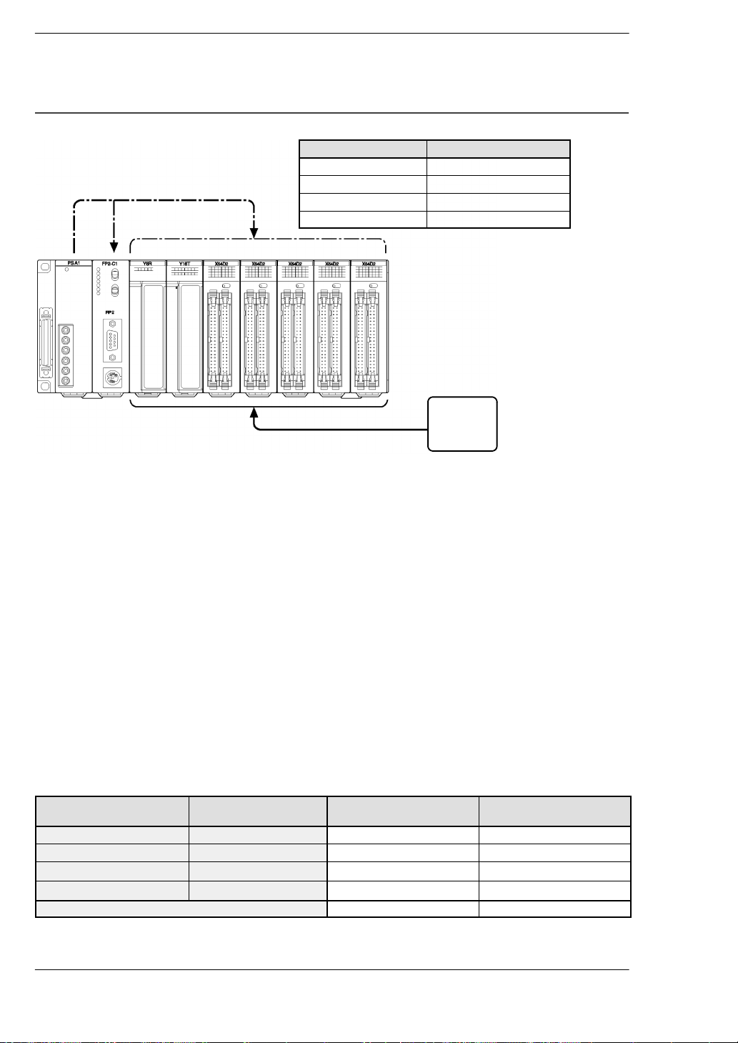
Example of current consumption calculation
The table below shows the combination of typical units on a 9-module type backplane.
Type Number of units and
backplane used
CPU (FP2−C1) 1 410 0
Backplane (FP2−BP09) 1 60 0
Input unit (FP2−X16D2) 3
Output unit (FP2−Y16R) 4
Total current consumption 1130 1024
1 − 12
Current consumption at
5V DC (mA)
60×3=180 8×16×3 = 384
120×4=480 160×4=640
Current consumption at
24V DC (mA)
Page 31

OverviewFP2/FP2SH
FP2
CPU
FP2SH
CPU
Backplane
ac p a e
type
pututC
put
Output
eay
out
a s sto
/O
ed
te ge t
High speed
Pulse
I/O
osto g
osto g
f
ype)
type)
as
osto g
osto g
ype)
type)
as
1.2 Unit Types and Combinations
Table of current consumption at 5V DC
Type Part number Current con-
FP2 CPU
FP2SH CPU
Backplane
Backplane H type
Input unit DC input
Output
unit
I/O mixed
unit
Intelligent
unit
Relay output
Transistor
output
32-point 24V DC input/32-point connector NPN output type FP2−XY64D2T, FP2−XY64D7T 160 or less
32-point 24V DC input/32-point connector PNP output type FP2−XY64D2P, FP2−XY64D7P 160 or less
Analog input unit (Voltage/current type) FP2−AD8VI 400 or less
Analog input unit (Channel type) FP2−AD8X 300 or less
RTD input unit FP2−RTD 300 or less
Analog output unit FP2−DA4 600 or less
High−speed
counter unit
Pulse I/O
unit
Positioning
unit
Positioning
unit (Multi-astype
unction
t
Positioning
unit RTEX
Positioning
unit (Inter-astype
polation
t
Serial data unit FP2−SDU 60 or less
Multi communication unit
with Communication block (1−unit or 2−unit)
16-point terminal type, 12 to 24V DC FP2−X16D2 60 or less
32-point connector type, 24V DC FP2−X32D2 80 or less
64-point connector type, 24V DC FP2−X64D2 100 or less
6-point terminal type FP2−Y6R 50 or less
16-point terminal type FP2−Y16R 120 or less
16-point terminal NPN type FP2−Y16T 100 or less
32-point connector NPN type FP2−Y32T 130 or less
64-point connector NPN type FP2−Y64T 210 or less
16-point terminal PNP type FP2−Y16P 80 or less
32-point connector PNP type FP2−Y32P 130 or less
64-point connector PNP type FP2−Y64P 210 or less
NPN FP2−HSCT 450 or less
PNP FP2−HSCP 450 or less
NPN FP2−PXYT 500 or less
PNP FP2−PXYP 500 or less
2-axis type FP2−PP2 225 or less
4-axis type FP2−PP4 400 or less
2-axis
4-axis
type
2-axis type FP2−PN2AN 300 or less
4-axis type FP2−PN4AN 300 or less
8-axis type FP2−PN8AN 300 or less
2-axis
4-axis
type
Transistor output type FP2−PP21 200 or less
Line driver output type FP2−PP22 200 or less
Transistor output type FP2−PP41 350 or less
Line driver output type FP2−PP42 350 or less
Transistor output type FP2−PP2T 300 or less
Line driver output type FP2−PP2L 300 or less
Transistor output type FP2−PP4T 300 or less
Line driver output type FP2−PP4L 300 or less
FP2−C1 410 or less
FP2−C1D 530 or less
FP2−C1SL 630 or less
FP2−C1A 1060 or less
FP2−C2L 750 or less
FP2−C2 750 or less
FP2−C2P 750 or less
FP2−C3P 750 or less
FP2−BP05 5 or less
FP2−BP07 60 or less
FP2−BP09 60 or less
FP2−BP12 60 or less
FP2−BP14 60 or less
FP2−BP11MH 5 or less
FP2−BP10EH 60 or less
FP2−MCU 480 or less
sumption at
5V DC (mA)
next page
1 − 13
Page 32

1.2 Unit Types and Combinations
Intelligent
FNS
unit
FP FNS
FMU
unit
pututC
put
Outpututeay
output
a s sto
/Oedut
3pot
C
put/3 po t
co ecto
6
,
output
type
FP2 XY64D7P
FP2/FP2SHOverview
Type Part number Current con-
sumption at
5V DC (mA)
Intelligent
unit
C.C.U. FP2−CCU 60 or less
S-LINK unit FP2−SL2 130 or less
Multi-wire link unit FP2−MW 220 or less
Remote I/O Slave Unit FP2−RMS 150 or less
ET−LAN unit FP2−ET1 670 or less
MEWNET−VE Link unit FP2−VE 670 or less
FNS unit
FMU unit
FNS unit FP2−FNS 55 or less
FP−FNS
Block
PROFIBUS FP2−DPV1−M 450 or less
Device Net FP2−DEV−M 150 or less
CAN open FP2−CAN−M 450 or less
PROFIBUS AFPN−AB6200 230 or less
Device Net AFPN−AB6201 65 or less
CAN open AFPN−AB6218 65 or less
Table of current consumption at 24V DC
Type Part number Current consumption at
Input unit DC input 16-point terminal type, 12 to 24V DC FP2−X16D2 8 or less per one point
32-point connector type, 24V DC FP2−X32D2 4.3 or less per one point
64-point connector type, 24V DC FP2−X64D2 4.3 or less per one point
Output unit Relay output 6-point terminal type FP2−Y6R 70 or less
16-point terminal type FP2−Y16R 160 or less
Transistor
output
I/O mixed unit 32-point 24V DC input/32-point connector NPN
output type
32-point 24V DC input/32-point connector PNP
output type
16-point terminal NPN type FP2−Y16T 120 or less
32-point connector NPN type FP2−Y32T 140 or less
64-point connector NPN type FP2−Y64T 250 or less
16-point terminal PNP type FP2−Y16P 70 or less
32-point connector PNP type FP2−Y32P 150 or less
64-point connector PNP type FP2−Y64P 270 or less
FP2−XY64D2T,
FP2−XY64D7T
FP2−XY64D2P,
FP2−XY64D7P
24V DC (mA)
Input: 4.3 or less per one point
Output: 120 or less
Input: 4.3 or less per one point
Output: 130 or less
1 − 14
Notes
• The input unit displays the current flowing to the internal cir-
cuit. The other units display the current value required to drive
the internal circuit. This value does not include the load current of the output unit.
• Refer to the manual of the particular unit you are using to
confirm the current consumed at 24V by the S-LINK units,
Positioning units, High−speed counter units and Pulse I/O
units.
Page 33

1.3 Expansion Function
1.3.1 Computer Link
OverviewFP2/FP2SH
1.3 Expansion Function
1:1 communication
The FP2 CPU can be directly
connected to a computer through
the COM (RS232C) port.
PC
FP2/FP2SH
COM port
Commercially available
RS232C cable
Two-core cable (RS485)
(VCTF0.75 × 2C)
1:N communication
A C-NET adapter can be used to enable
communication for a number of programmable
controllers.
C-NET adapter
(AFP8536/AFP8532)
Commercially available RS232C cable
S2 type
S2 type
A maximum of 32 stations can be connected.
PC
FP2/FP2SH
FP2/FP2SH
Since a COM (RS232C) port and TOOL (RS232C) port comes standard on the CPU for
the FP2/FP2SH, direct communication with the computer can be achieved without the
addition of any intelligent units.
Using a host computer program, the relay conditions and register contents of the CPU
can be read and written.
With communications from a host computer, communication programs are unnecessary
on the CPU side.
1 − 15
Page 34

1.3 Expansion Function
C
d
Half
duplexHalf
dupl
Table of specifications
Item
ommunication metho
Synchronization method Start−stop synchronous system
Communication path RS232C cable Two-core cable
Transmission distance Max. 15m/49.2ft. Max. 1200m/3,937ft.
Transmission speed
(Baud rate)
Transmission code ASCII
Transmission format Stop bit: 1 bit/2 bits
Description
1:1 communication 1:N communication
ex
2
1200bps/2400bps/4800bps/9600bps/
19200bps/38400bps/57600bps/115.2Kbps
Parity check: none/even/odd
Character bits: 7 bits/8 bits
(VCTF 0.75mm
9600bps/19200bps
Necessary devices in configuration
1:1 communication 1:N communication
FP2/FP2SH
Commercially available computer
Commercially available RS232C cable
(AFB85813/AFB85853 or equivalent)
FP2/FP2SH
Commercially available computer
Commercially available RS232C cable
(AFB85813/AFB85853 or equivalent)
C-NET adapter (AFP8536/AFP8532) × 1 piece
C-NET adapter S2 type (AFP15402) × number of PLC
2
Two-core cable (VCTF 0.75mm
)
FP2/FP2SHOverview
× 2C)
1 − 16
Page 35

1.3.2 Connection of MODEM
OverviewFP2/FP2SH
1.3 Expansion Function
1:1 communication
Connections to a MODEM can be
made using the COM port.
MODEM MODEM
Public line
Commercially available
RS232C cable
FP2/FP2SH
PC
Two-core cable (RS485)
(VCTF0.75 × 2C)
COM port
1:N communication
Using the C-NET adapter enables MODEMs to be
connected for multiple programmable controller.
MODEM MODEM
Public line
Commercially available
RS232C cable
PC
C-NET adapter
(AFP8536/AFP8532)
S2 type
S2 type
FP2/FP2SH
FP2/FP2SH
A maximum of 32 stations can be connected.
The CPU of the FP2/FP2SH includes a COM (RS232C) port and TOOL (RS232C)
port as standard equipment, making it possible to connect a MODEM to perform programming and computer linking from a remote location using a public telephone line.
When the power supply of FP2/FP2SH is turned on, it will verify whether a MODEM is
connected, and, if a MODEM is, it will automatically transmit the AT command to set the
MODEM for automatic reception.
Since the reading and writing of the relay conditions and register contents of the programmable controller can be performed from the host computer, this function is
applicable for remote monitoring systems.
When using the TOOL port, you can use programming tool software (NPST-GR/FPWIN
GR) and perform reading and writing of the programmable controller program and maintenance operations via MODEM.
During 1:1 communication using the COM port, an error alarm can be issued from the
programmable controller.
1 − 17
Page 36

1.3 Expansion Function
Table of specifications
FP2/FP2SHOverview
Item
Communication method Half duplex
Synchronization method Start−stop synchronous system
Transmission speed
(Baud rate)
Transmission code ASCII
Transmission format Character bit: 7 bits, parity check: odd and stop bit: 1 bit
Description
1:1 communication 1:N communication
2,400bps/4,800bps/9,600bps/19,200
bps
Character bit: 8 bits, parity check: none and stop bit: 1 bit
9,600bps/19,200bps
Necessary devices in configuration
1:1 communication 1:N communication
FP2/FP2SH
Commercially available computer
MODEM
Commercially available RS232C cable
* When using the TOOL port, an FP PC cable M5
type (AFC8513) and a self-made cable are necessary.
FP2/FP2SH
Commercially available computer
MODEM
Commercially available RS232C cable
C-NET adapter (AFP8536/AFP8532) × 1 piece
C-NET adapter S2 type (AFP15402) × number of PLC
2
Two-core cable (VCTF 0.75mm
)
1 − 18
Page 37

1.4 Programming Tools
1.4.1 Tools Needed for Programming
Necessary tools
FP2/FP2SH
3
Commercially available
computer
2
OverviewFP2/FP2SH
1.4 Programming Tools
1
Install
1
Programming tool software
Programming tool software
This is a program editing, debugging and document creating software package
that can be used with all programmable controllers in the FP series.
2
FP PC cable
This cable needed for connection between the FP2/FP2SH and the computer.
When connecting to a computer (IBM PC/AT or 100% compatible), use a com-
mercially available adapter.(
section 1.4.2 )
For the following, use commercially available products.
3
Commercially available computer
1 − 19
Page 38

1.4 Programming Tools
Wind
p
1.4.2 Software Environment and Suitable Cable
Standard ladder diagram tool software FPWIN−GR Ver.2
FP2/FP2SHOverview
Type of software OS
FPWIN GR Ver. 2
English−language
menu
Full type Windows 98
Upgraded version
(Operating system)
Windows Me
Windows XP
Windows Vista
ows 2000
Hard disk capacity Product No.
40MB or more AFPS10520
AFPS10520R
Note
1) Ver.1.1 must be installed to install the upgrade version.
2) Ver.2.0 can be upgraded to Ver. 2.1 or later free of charge at
our web site (http://industrial.panasonic.com/ac/e/dl_center/
software/).
Conforms to IEC61131−3 programming tool software FPWIN−Pro Ver.6
Type of software OS
FPWIN GR Ver. 6 English−language menu
(Operating system)
Windows 2000
Windows XP
Windows Vista
Hard disk capacity Product No.
100MB or more AFPS50560
Note
1) The upgrade version is not available for Ver.6.
2) Ver.6.0 can be upgraded to Ver. 6.1 or later free of charge at
our web site (http://industrial.panasonic.com/ac/e/dl_center/
software/).
Type of computer and suitable cable
For the connection between a computer (RS232C) and the control unit (RS232C)
D−sub connector cable
PC side connector PLC side connector Specifications Product No.
D−sub 9−pin Mini DIN round 5−pin L type (3 m) AFC8503
Mini DIN round 5−pin Straight type (3 m) AFC8503S
Note
A USB/RS232C conversion cable is necessary to connect with a
personal computer without a RS232C port using a PC connection
cable.
1 − 20
Page 39

OverviewFP2/FP2SH
1.4 Programming Tools
1.4.3 Tools Needed for ROM Creating
When Creating ROM with a Commercially Available ROM Writer with Optional Memory (FROM)
Necessary tools
1
Programming tool software and cable ( section 1.4.1)
Use a commercially available computer installed with the programming tool software and an FP PC cable.
2
Optional memory FROM
For FP2, FP2-EM4 (SST−29EE010−120−4C−PH or equivalent, SILICOM STORAGE TECHNOLOGY, INC.)
For FP2SH, AFP5208 (SST−29EE020−150−4C−PH or equivalent, SILICOM
STORAGE TECHNOLOGY, INC.)
3
Optional memory EPROM
For FP2, FP2-EM5 (M27C1001−12F1 or equivalent, SGS−THOMSON MICROELECTRONICS)
For FP2SH, AFP5209 (M27C2001−150F1 or equivalent, SGS−THOMSON MICROELECTRONICS)
For the following, use commercially available products.
4
Commercially available ROM writer
2
A ROM writer than can be used with memories
and3.
Note
1) The above explanation describes the case where the memory
unit is used in combination with the F−ROM and EP−ROM. As
the nonvolatile memory has been implemented in the memory
unit (Model number AFP2208), a commercial ROM writer cannot be used for writing.
2) The parts for the optional memory to be used differ depending
on FP2 or FP2SH.
1 − 21
Page 40

FP2/FP2SHOverview
1.4 Programming Tools
When Creating ROM with Programming Tool Software and a Commercially
Available ROM Writer
Necessary tools
1
Programming tool software ( section 1.4.1)
Use a commercially available PC installed with the programming tool software.
2
Optional memory EPROM
For FP2, FP2-EM5 (M27C1001−12F1 or equivalent, SGS−THOMSON MICROELECTRONICS)
For FP2SH, AFP5209 (M27C2001−150F1 or equivalent, SGS−THOMSON MICROELECTRONICS)
For the following, use commercially available products.
3
Commercially available ROM writer
A ROM writer than can be used with memory
4
Commercially available centronics cable or commercially available
2
.
RS232C cable
Use a cable that conforms with the specifications of the ROM writer.
Note
1) The above explanation describes the case where the memory
unit is used in combination with the EP−ROM. As the nonvolatile memory has been implemented in the memory unit (Model
number AFP2208), a commercial ROM writer cannot be used
for writing.
1 − 22
2) The parts for the optional memory to be used differ depending
on FP2 or FP2SH.
Page 41

Chapter 2
Parts and Functions
Page 42

FP2/FP2SHParts and Functions
2 − 2
Page 43

2.1 Backplane and Expansion Cable
2.1 Backplane and Expansion Cable
2.1.1 Backplane
1 2
Parts and FunctionsFP2/FP2SH
3
7
6 5 4
Parts Terminology and Functions
1
Backplane mounting holes
for mounting the backplane to the control panel. Use M4 screw for the mounting.
2
Unit guides
Align the tab on the unit with this guide when installing the unit to the backplane.
For use as the basic backplane (CPU backplane), from the left side of the backplane, install the power supply unit, CPU, I/O units, and intelligent units, in this
order.
For use as an expansion backplane, from the left side of the backplane, install
the power supply unit, I/O units, and intelligent units, in this order.
3
Connector for various units
Install a CPU, input, or output unit. When installing a CPU, be sure to install it
next to a power supply unit.
4
DIN rail attachment lever
allows attachment to a DIN rail.
5
Unit installation holes
for installing the unit to the backplane. Use the screw supplied with the unit for
installation.
6
Connector for power supply unit
7
Connector for expansion cable
for more details regarding the cable connecting, refer to section 4.1.3.
This connector is not present on a 5-module type backplane.
2 − 3
Page 44

2.1 Backplane and Expansion Cable
Type of Backplane
FP2/FP2SHParts and Functions
Type Use Number of
module
5-module type Basic system only 5 FP2−BP05 Approx. 180g
7-module type Basic and expansion
9-module type
12-module type 12 FP2−BP12 Approx. 470g
14-module type 14 FP2−BP14 Approx. 530g
system
7 FP2−BP07 Approx. 280g
9 FP2−BP09 Approx. 350g
Part
number
Weight
2 − 4
Page 45

2.1 Backplane and Expansion Cable
2.1.2 Basic Backplane H Type (FP2−BP**MH)
Parts and FunctionsFP2/FP2SH
1
7
2
3
6
5
8
4
Parts Terminology and Functions
1
Backplane mounting holes
for mounting the backplane to the control panel. Use M4 screw for the mounting.
2
Unit guides
Align the tab on the unit with this guide when installing the unit to the backplane.
From the left side of the backplane, install the power supply unit, CPU, I/O units,
and intelligent units, in this order.
3
Connector for various units
Install various unit.
4
DIN rail attachment lever
allows attachment to a DIN rail.
5
Unit installation holes
for installing the unit to the backplane. Use the screw supplied with the unit for
installation.
6
Connector for power supply unit
7
Connector for expansion cable
for more details regarding the cable connecting, refer to section 4.1.3.
8
Connector for CPU unit
The position to install the CPU unit is fixed.
Type of Backplane
Type Use Number of module Part number Weight
11-module type Basic system only 11 FP2−BP11MH Approx. 470g
Note
The color of letters on the printed board is yellow to make easier
to distinguish the FP2 backplane H type from the FP2 backplane.
2 − 5
Page 46

2.1 Backplane and Expansion Cable
2.1.3 Expansion Backplane H Type (FP2−BP**EH)
FP2/FP2SHParts and Functions
1
8
7
6
2
3
5
4
Parts Terminology and Functions
1
Backplane mounting holes
for mounting the backplane to the control panel. Use M4 screw for the mounting.
2
Unit guides
Align the tab on the unit with this guide when installing the unit to the backplane.
From the left side of the backplane, install the power supply unit, I/O units, and
intelligent units, in this order.
3
Connector for various units
Install I/O unit.
4
DIN rail attachment lever
allows attachment to a DIN rail.
5
Unit installation holes
for installing the unit to the backplane. Use the screw supplied with the unit for
installation.
6
Connector for power supply unit
7
Connector for expansion cable
for more details regarding the cable connecting, refer to section 4.1.3.
8
Board number setting switch
is used to set a bord number for the expansion backplane. I/O numbers are
assigned according to the board number set the board numbers in increasing
order, 1, 2 and 3 from the board close to the basic backplane.
(Do not set 4 or higher numbers as proper operation cannot be guaranteed).
Type of Backplane
Type Use Number of module Part number Weight
10-module type Expansion system only 10 FP2−BP10EH Approx. 470g
Note
The color of letters on the printed board is yellow to make easier
to distinguish the FP2 backplane H type from the FP2 backplane.
2 − 6
Page 47

Parts and FunctionsFP2/FP2SH
2.1 Backplane and Expansion Cable
2.1.4 Expansion Cable
Order number Length Ferrite core Weight
FP2−EC 60 cm 1 Approx. 200 g
FP2−EC2 2m 2 Approx. 400 g
Note) With the backplalne H type, the total cable length can be arranged within 3.2 m.
Ferrite core
Note
Connect the connector on the side of the ferrite core to the CPU
backplane.
2 − 7
Page 48

2.2 FP2 CPU
2.2 FP2 CPU
2.2.1 Standard Type CPU (FP2−C1)
FP2/FP2SHParts and Functions
Parts Terminology and Functions
1
Status indicator LEDs ( page 2 − 9)
display the operating condition and error statuses.
2
Initialize/test switch ( page 2 − 9)
is used to clear the errors, initializes the operation memory and set the test
operation.
3
Mode selector ( page 2 − 10)
is used to change the operation mode of the PLC.
4
COM port (RS232C) ( page 2 − 11)
is used to connect a computer or general−serial devices.
5
Tool port (RS232C)
is used to connect a programming tool.
6
Operation condition switches ( page 2 − 10)
are used to set the baud rate of the programming tool, to select the program
memory and to select the writing operation for the program memory.
7
Memory backup battery
for backup of the internal memory (RAM).
Part number: AFC8801 (CR2450 or equivalent)
Note
The settings of the operation condition switches become active
when the power is turned on.
2 − 8
Page 49

Parts and FunctionsFP2/FP2SH
LED
D
Switch
O
2.2 FP2 CPU
Status Indicator LEDs
These LEDs display the current mode of operatin or the occurrence of error.
escription
RUN (green) This lights in the RUN mode, to indicate that the program is being executed.
PROG. (green)
TEST (green) This lights in the test operation mode.
BREAK (green) This lights in the operation halts at a break during a test run or halts during the step
ERROR (red) This lights if an error is detected during the self-diagnostic function.
BATT. (red) This lights when the voltage of the backup battery drops below a specific value.
ALARM (red) This lights if a hardware error occurs, or if operation slows because of the program,
It flashes during forced input/output.
This lights in the PROG. mode. Operation stops while this LED is lighted.
It flashes when waiting for connection of slave station on remote I/O system.
If the memory is initialized, the brightness dims, indicating that initialization is being
executed.
operation mode for the test run.
and the watchdog timer is activated.
Initialize/Test Switch
This switch clears errors, initializes the operation memory and sets the test operation
mode.
position
INITIALIZE (upward)
(center) The switch should normally be left in this position.
TEST
(downward)
peration mode
In the PROG. mode:
The contents of the operation memory are initialized. However, the system register
(including the I/O map) and the program are not initialized. If the error of self-diagnostic error code 42 or lower is occured, the special internal relays R9000 to R9008
and the special data register DT90000 are not cleared.
In the RUN mode:
Operation errors, remote I/O system errors, and battery errors are cleared.
Setting this switch to the downward position in the PROG. mode, accesses the test
mode. Switching to the RUN mode in this state, initiates test operation.
To return from the test mode to the normal operation, return this switch to the center
position in the PROG. mode.
Note
By turning on the initialize/test switch while in the PROG.mode,
you can be specify the type of operation memory to be cleared
with system register 4.
2 − 9
Page 50

FP2/FP2SHParts and Functions
Sel
O
2.2 FP2 CPU
Mode Selector
Use the mode selector to start and stop the operation. For test operations, set the initialize/test switch to TEST position.
ector position
RUN (upward) This sets the RUN mode. The program is executed, and operation begins.
REMOTE
(center)
PROG. (downward) This sets the PROG. mode. In this mode, programming can be done using tools, the
peration mode
This enables operation to be started and stopped from a programming tool. At the
stage where the selector is changed, when switching from the PROG. to the REMOTE mode, the system remains in the PROG. mode and when switching from the
RUN to the REMOTE mode, it remains in the RUN mode.
test operation mode can be accessed and the operation memory can be initialized
using the Initialize/tset switch.
Operation Condition Switches
Switch Item
SW1 Baud rate for tool port System register setting
SW2 Program memory selection Internal RAM Optional memory (ROM)
SW3 Program memory protection Write enabled Write protected
SW4 Not used — —
Switch position
off (factory setting) on
9,600bps
(Default value: 19,200bps)
2 − 10
Page 51

COM Port (RS232C)
g
Pin alignment
Note
The serial data communication control instruction (F144) cannot
be executed unless pin 5 is turned on.
Parts and FunctionsFP2/FP2SH
2.2 FP2 CPU
Pin
number
1
2 Send data SD →
3 Received data RD ←
4 Request to send (always on) RS →
5 Clear to send CS ←
6
7
8
9 Equipment ready (always on) ER →
Signal name Signal direction
PLC
(Field device)
Frame ground FG
Not used −
Signal ground terminal SG
Not used −
Destination
Communications specifications
Electrical characteristics conform to EIA RS232C.
The baud rate and transmission format are decided by system registers.
The table below shows the settings in the default state.
Item Description
Mode selection Computer link
Baud rate
Data bit length 8 bits
Parity check Odd parity
Start bit length 1 bit
Stop bit length 1 bit
19200 bps
The starting and ending codes when using a computer link are determined by the MEWTOCOL−COM.
When using the general−purpose communication function (serial data communication
control instruction “F144”), the setting of system register 412 should be changed.
The serial data communication control instruction can be used to switch between the
computer link function and the general−purpose communication function.
If the transmission speed is 38,400 bps or higher, the transmission distance over which
communication is possible is limited to within 3m/9.84ft.
2 − 11
Page 52

2.2 FP2 CPU
2.2.2 CPU with 64 Points Input (FP2−C1D)
Parts Terminology and Functions
1
Status indicator LEDs ( page 2 − 9)
display the operating condition and error statuses.
FP2/FP2SHParts and Functions
2
Initialize/test switch ( page 2 − 9)
is used to clear the errors, initializes the operation memory and set the test
operation.
3
Mode selector ( page 2 − 10)
is used to change the operation mode of the PLC.
4
COM port (RS232C) ( page 2 − 11)
is used to connect a computer or general−serial devices.
5
Tool port (RS232C)
is used to connect a programming tool.
6
Input indicators (32 points)
Indicate the input on/off states.
7
Selector for input indicators
switch between the first 32 points and second 32 points of the 64 points input
LED display.
8
Input connectors
CN1: X0 to X1F
CN2: X20 to X3F
9
Operation condition switches ( page 2 − 10)
are used to set the baud rate of the programming tool, to select the program
memory and to select the writing operation for the program memory.
2 − 12
next page
Page 53

10
p
Memory backup battery
for backup of the internal memory (RAM).
Part number: AFC8801 (CR2450 or equivalent)
Note
The settings of the operation condition switches become active
when the power is turned on.
CPU with 64 Points Input Specifications
Item Description
Number of input point 64 points
Insulation method Optical coupler
Rated input voltage 24V DC
Rated input current Approx. 4.3mA (at 24V DC)
Input impedance Approx. 5.6kΩ
Input voltage range 20.4 to 26.4V DC
Min. on voltage/Min. on current 19.2V/4mA
Max. off voltage/Max. off current 5.0V/1.5mA
Response time off → on 0.2ms or less
on → off 0.3ms or less
Input points per common 32 points per common
(Either the positive or negative of the input power supply can be
connected to common terminal.)
Operating indicator 32-dot LED display (lit when on, switching)
External connection method Two 40-pin connectors
Parts and FunctionsFP2/FP2SH
2.2 FP2 CPU
Note
Keep the number of input points which are simultaneously on
within the following range as determined by the input voltage and
ambient temperature.
26.4V DC
24V DC
Number of
points which are
simultaneously
on
50/
55/
122
Ambient temperature (°C/°F)
131
2 − 13
Page 54

2.2 FP2 CPU
Internal Circuit Diagram
FP2/FP2SHParts and Functions
Input indicator LED
Input
24V DC
COM
5.6kΩ
560Ω
Pin Layout
24V DC 24V DC
Internal circuit
The COM pins of each connector are connected internally.
2 − 14
Page 55

Parts and FunctionsFP2/FP2SH
Item
Description
2.3 Expansion Memory Unit and ROM (for FP2 CPU)
2.3 Expansion Memory Unit and ROM (for FP2 CPU)
Expansion Memory Unit
Parts Terminology
1
Mounting knob
2
Connector (rear side)
3
ROM IC socket (for FP2−EM3, FP2−EM6 and FP2−EM7)
Install the optional memory FROM or EPROM.
Type of Expansion Memory Unit
Item
Comment
input
function
(flash ROM)
Calendar/
timer function
Expansion
RAM
ROM IC
socket
Part number
FP2−EM1 FP2−EM2 FP2−EM3 FP2−EM6 FP2−EM7
Available
128k byte
Available Available Available Not
Not
available
Not
available
Available
128k byte
Available Available Available Not
Not
available
Available
512k byte
Available Available Available Enables the program to be co-
Not
available
available
Not
available
Not
available
available
Description
Writes the I/O comments, remarks and block comments in
the program to the FP2 CPU.
Allows operations using the calendar/timer function.
Increases the program memory
from approx. 16K to approx.
32K. Also enables use of the
trace function.
pied to ROM for ROM operation.
Type of ROM
Type Description Part number
FROM Equivalent to the 29EE010−120−4C−PH (SILICON STORAGE TECHNOLOGY,
INC.). Enables writing with the operation of the programming tools when attached
to the CPU.
EPROM Equivalent to the M27C1001−12F1 (SGS-THOMSON MICROELECTRONICS).
A commercially available ROM writer is required for writing.
FP2−EM4
FP2−EM5
2 − 15
Page 56

2.3 Expansion Memory Unit and ROM (for FP2 CPU)
Installation Procedure
Installing the expansion memory unit
Procedure:
1. Send the program and data to the personal computer using the programming tool software (NPST−GR or FPWIN GR).
2. Save the program and data to the disk.
3. Set the mode selector of the FP2 CPU to PROG.
4. Turn off the power supply and remove the FP2 CPU.
5. Remove the retaining screw.
Retaining screw
FP2/FP2SHParts and Functions
FP2 CPU
6. Install the expansion memory unit.
7. Secure the expansion memory unit with the retaining screw.
Retaining screw
Expansion memory unit
Connector
FP2 CPU
8. Install the FP2 CPU to the backplane and turn on the power supply.
9. Perform a program clear using the programming tool software.
10. Send to the FP2 CPU the program and data saved in step 2 above.
(For the FP2−EM2, FP2−EM3 and FP2−EM6, continue with the procedures below.)
11. At the “NPST Configuration” menu for NPST−GR or “Select PLC Type”
menu for FPWIN GR of programming tool software, set the PLC type to
FP2(32K).
12. Set the program capacity with system register 0.
2 − 16
Page 57

Installing the ROM
Procedure:
1. Release the lock for the ROM IC socket.
2. Make sure that the lead pitch of the ROM matches that of the socket.
3. Making sure that the orientation is correct, insert the ROM into the
socket.
4. Return the lock to the locked position completely after the ROM is
inserted.
Parts and FunctionsFP2/FP2SH
2.3 Expansion Memory Unit and ROM (for FP2 CPU)
LockLock release
ROM
Note
When removing or installing the expansion memory unit, the contents of the internal RAM may be erased. Therefore, always save
the program onto a disk before beginning the removal and installation operations. During the installation or removal operations,
do not touch the leads on any of the IC with your hands.
2 − 17
Page 58

2.4 FP2SH CPU
yp
p
2.4 FP2SH CPU
FP2/FP2SHParts and Functions
Type of FP2SH CPU
Type Operation
32k steps
Standard
type CPU
60k steps
Standard
type CPU
60k steps
CPU with
IC memory
card interface
120k steps
CPU with IC
memory
card interface
speed RAM
From 0.03μs
Standard type CPU
Internal
32k steps Not
60k steps Not
60k steps Not
120k
steps
Optional memory Function
Expansion
RAM
available
available
available
Not
available
Small PC card
compliant type CPU
ROM IC card Calendar/
Available
(Optional)
Available
(Optional)
Available
(Built-in)
Available
(Built-in)
Not
available
Not
available
Available
(Optional)
Available
(Optional)
timer
Available
(Built-in)
Available
(Built-in)
Available
(Built-in)
Available
(Built-in)
Comment
memory
Available
(Built-in)
Available
(Built-in)
Available
(Built-in)
Available
(Built-in)
Part
Model
number number
FP2-C2L AFP2221
FP2-C2 AFP2231
FP2-C2P AFP2235
FP2-C3P AFP2255
2 − 18
Page 59

2.4.1 32k/60k Step Standard Type CPU (FP2-C2L/FP2-C2)
Parts Terminology and Functions
1
Status indicator LEDs ( page 2 − 9)
display the operating condition and error statuses.
Parts and FunctionsFP2/FP2SH
2.4 FP2SH CPU
2
Initialize/test switch ( page 2 − 9)
Setting the switch to the ”INITIAL” side clears errors and initializes the operation
memory. Setting the switch to the ”TEST” side puts the PLC in the test operation
mode.
3
Mode selector ( page 2 − 10)
is used to change the operation mode of the PLC.
This is used to switch between the RUN, REMOTE, and PROG. modes.
4
COM port (RS232C) ( page 2 − 11)
is used to connect a computer or general−serial devices .
5
Tool port (RS232C)
is used to connect a programming tool.
6
Operation condition switches ( page 2 − 21)
are used to set the baud rate of the programming tool, to select the program
memory and to select the writing operation for the program memory.
7
Memory backup battery
for backup of the internal memory (RAM).
Part number: AFC8801 (CR2450 or equivalent)
2 − 19
Page 60

2.4 FP2SH CPU
2.4.2 CPU with IC Memory Card Interface (FP2-C2P/FP2−C3P)
Parts Terminology and Functions
1
Status indicator LEDs ( page 2 − 9)
display the operating condition and error statuses.
2
IC memory card access LED
Illuminates when data is being read from or written to the IC memory card.
FP2/FP2SHParts and Functions
3
IC memory card slot
is used when installing an optional IC memory card.
4
IC memory card eject button
Pressing this button ejects the IC memory card.
5
Initialize/test switch ( page 2 − 9)
Setting the switch to the “INITIAL” side clears errors and initializes the operation
memory. Setting the switch to the “TEST” side puts the PLC in the test operation
mode.
6
Mode selector ( page 2 − 10)
is used to change the operation mode of the PLC.
This is used to switch between the RUN, REMOTE, and PROG. modes.
7
IC memory card access enable switch
Setting this switch to the “on” (upward) side enables data to be read and written
to the IC memory card.
8
COM port (RS232C) ( page 2 − 11)
is used to connect a computer or general−serial devices .
9
Tool port (RS232C)
is used to connect a programming tool.
next page
2 − 20
Page 61

Parts and FunctionsFP2/FP2SH
2.4 FP2SH CPU
10
Operation condition switches
are used to set the baud rate of the programming tool, to select the program
memory and to select the writing operation for the program memory.
11
Memory backup battery
for backup of the internal memory (RAM).
Part number: AFC8801 (CR2450 or equivalent)
Operation Condition Switches
ON
SW4
SW3
SW2
SW1
Switch Item
SW1 Baud rate for tool port System register setting
SW2 Program memory selection Internal RAM External memory
SW3 Program memory protection Write enabled Write protected
SW4 External memory selection ROM IC memory card
Switch position
off (factory setting) on
9,600bps
(Default value: 19,200bps)
2 − 21
Page 62

2.4 FP2SH CPU
2.5 Expansion Memory Unit and ROM (for FP2−C2L/FP2-C2)
Parts Terminology
AFP2207(FP2−EM7) AFP2208
1
Mounting knob
2
Connector (rear side)
3
ROM IC socket
Install the optional memory FROM or EPROM.
FP2/FP2SHParts and Functions
Type of Expansion Memory Unit
Type Function Part number Model number
Expansion
memory unit
Socket for installing the ROM in the CPU FP2−EM7 AFP2207
Nonvolatile memory−implemented memory unit — AFP2208
Note
The FP2−EM1, FP2−EM2, FP2−EM3, and FP2−EM6 expansion
memory units for the FP2 cannot be used.
As for the memory unit AFP2208, the ROM is not removable.
Type of ROM
Type Function Part number
FROM Equivalent to the 29EE020−150−4C−PH (SILICON STORAGE TECHNOLOGY,
INC.). Enables writing with the operation of the programming tools when attached
to the CPU.
EPROM Equivalent to the M27C2001−150F1 (SGS-THOMSON MICROELECTRONICS).
A commercially available ROM writer is required for writing.
AFP5208
AFP5209
Installation Procedure
For detailed information about the installation of expansion memory unit page 2 − 16
For detailed information about the installation of ROM
2 − 22
page 2 − 17
Page 63

2.6 IC Memory Card (for FP2-C2P/FP2-C3P)
2.6 IC Memory Card (for FP2-C2P/FP2-C3P)
AIC50020, AIC52000 AFP2209
Parts and FunctionsFP2/FP2SH
3
2
3
1
Parts and Functions
① Write protect switch
Switch position Purpose
ON (right) Read−only of the data
OFF (left) Write enable of the data
② Lock switch
It fixes the battery holder.
Switch position Purpose
LOCK (right)
RELEASE (left)
Lock position
Release position
Note) The lock switch is automatically back to the LOCK position from the RELEASE
position when removing the battery holder.
③ Battery holder
A battery for memory backup is installed. (A battery is supplied with the product.)
Product number for purchasing separately: AFP2806
Role of IC Memory Card
The IC memory card can be used as a memory to which programs can be saved and copied, or as an expanded memory to which data can be read and written in the program.
The IC memory card can be divided into two areas, a “format field” in which various programs are stored, and an “expanded memory field” used as a data memory.
2 − 23
Page 64

2.6 IC Memory Card (for FP2-C2P/FP2-C3P)
load
Program
toICCard
of
instruction
F13
(ICWT)
from
programs
Example:
A 2MB card can be formatted as 1 MB, with 1 MB being used
as a “format field” and the remaining 1 MB being used as an
“expanded memory field”.
The entire field can be used as a “format field” or as an “expanded memory field”, and the card used exclusively as a
memory card for saving programs or data memory.
If the FROM section is specified as the “expanded memory
field”, the card can be used only for reading data.
Types of IC Memory Cards
Type Memory
capacitynumber
FROM
type
SRAM
type
SRAM
type
2MB AIC50020 Data is written to IC memory
2MB
Part
AFP2209
AIC52000
(Discontinued
products)
Usage method
When used to store
programs
card using “Copy File to IC
Card” of programming tool
software.
Programs are written to IC
memory card using “Down-
programming tool software.
Programs can be written from
internal RAM to IC memory
card using “ROM ← RAM” of
programming tool software.
When used as
expanded memory field
Serves as dedicated memory
for reading data.
Data is written using programming tool software.
Data is read from IC memory
card using high−level instruction F12 (ICRD).
Writing of data to IC memory
card is done using high−level
”
Reading of data from IC
memory card is done using
high−level instruction F12
(ICRD).
FP2/FP2SHParts and Functions
Recommended
application
points
No battery backup is required, so
this is ideal for
saving programs.
Data can be read
.
to and written
,
so this is ideal for
use as expansion
data memory.
2 − 24
Notes
• Both the SRAM and FROM type can be divided into a “format
field” and an “expanded memory field” for use.
• When using the card as a program memory, there are four
ways to read programs:
− Programs are read automatically when the power is turned
on (IC memory card operation).
− Programs are read using the “ROM → RAM” operation of
programming tool software.
− Programs are read using the “IC Card Service” of programming tool software.
− Programs are read using the F14 (PGRD) instruction of the
sequence program.
Page 65

Parts and FunctionsFP2/FP2SH
2.6 IC Memory Card (for FP2-C2P/FP2-C3P)
Inserting and Removing the IC Memory Card
The IC memory card can be inserted or removed even when the FP2SH power is on.
To insert or remove the card when the power is on, be sure to follow the following procedure.
Inserting procedure:
1. Remove the cover of FP2SH CPU.
2. Set the IC memory card access enable switch to off
position.
Note
3. Insert the IC memory card.
Eject button
When using AFP2209, confirm if the battery is installed in the IC
memory card.
2 − 25
Page 66

2.6 IC Memory Card (for FP2-C2P/FP2-C3P)
4. Set the IC memory card access enable switch to on
position.
Removal procedure:
1. Verify that the IC memory card access LED is off. Set the
IC memory card access enable switch to off position.
FP2/FP2SHParts and Functions
2 − 26
2. Push the eject button and pull out the IC memory card.
Page 67

Parts and FunctionsFP2/FP2SH
2.6 IC Memory Card (for FP2-C2P/FP2-C3P)
Precautions when installing/removing the IC memory card
Do not try to insert and remove the IC memory card while the IC memory card access
enable switch is on. It could lead to damage of the memory contents or a malfunction
of CPU.
Do not use excessive force to the card or the section where card is installed.
Battery of the SRAM type IC memory card
AIC52000
A rechargeable battery is used. It cannot be exchanged.
AFP2209
An interchangeable battery is used. When you use for the first time, install the battery
included.
Note
If the battery voltage has dropped, the ERROR LED lights, and
error code K55 or K54 is stored in special data register DT90000.
Error codes can be confirmed using programming tools.
K54 The data on the IC memory card is not retained.
K55 The data on the IC memory card is guaranteed, but the
voltage of the internal battery has dropped.
*AIC52000: Power should continue to be supplied to the unit in
order to charge it.
*AFP2209: The replacement of memory backup battery is neces
sary. As the data saved in AFP2209 is overwritten
when replacing the battery, the data must be backed
up before the replacement.
Write protection of IC memory card
There is a write protect switch on the IC memory card. To prohibit writing to the IC
memory card, set this switch to “Write protect” position.
To write the program or data to the IC memory card, set the write protect switch to off
position.
2 − 27
Page 68

2.7 Power Supply Units
2.7 Power Supply Units
2.7.1 Power Supply Specifications
FP2/FP2SHParts and Functions
Parts Terminology and Functions
1
POWER LED
Turns on when power is applied.
2
Power supply terminal
is the terminal for power supply wiring. Uses M3 crimping (pressure connection)
terminals (
3
Ground terminal
section 4.2.1).
To minimize effects from noise and prevent electrical shocks, connect this terminal
to ground.
4
Alarm output terminal
Contact output terminals of the relay which turns on when the ALARM LED of the
CPU turns on. Normally closed contact (N.C.) and normally open contact (N.O.) are
available.
5
Unit installation screw
6
Temporary holding hook
2 − 28
Page 69

Parts and FunctionsFP2/FP2SH
p
2.7 Power Supply Units
Specifications
Item Description
Part number FP2−PSA1 FP2−PSA2 FP2−PSA3 FP2−PSD2
Size of unit 1−module 2−module
Input Rated voltage 100 to 120V AC 200 to 240V AC 100 to 240V AC 24V DC
Current consumption 0.4A or less
Surge current 40A or less 30A or less
Rated frequency 50Hz/60Hz —
Operating voltage
range
Output Output capacity at 5V Max. 2.5A Max. 5A Max. 5A
Alarm contact capacity 30V DC 1A
Alarm contact operation When the ALARM LED of CPU is lit
Alarm contact type 1c contact
Leakage current Between input and ground terminals, 0.75mA or less
Breakdown voltage 1500V AC for 1 minutes
Insulation resistance 100MΩ 500V DC (between input and ground terminals)
Guaranteed lifetime 20000 hours at 55°C/131°F
Overcurrent protection function Built-in overcurrent protection
Fuse Built-in
Terminal screw M3
(at 100V AC)
85 to 132V AC 170 to 264V AC 85 to 264V AC 20.4 to 31.2V DC
(between input and ground terminals)
0.2A or less
(at 200V AC)
0.7A or less
(at 100V AC)
0.4A or less
(at 200V AC)
(at 25°C/77°F)
2.5A or less
10A or less
(*1)
500V AC for 1
minutes (between
input and ground
terminals)
*1 The allowable variation in voltage after startup is 15.6V to 31.2V.
2 − 29
Page 70

2.8 Input and Output Units
2.8 Input and Output Units
2.8.1 Common Specifications of Input and Output Units
32
6
FP2/FP2SHParts and Functions
5
5
Parts Terminology and Functions
1
Input and output indicators
Indicate the input and output on/off states.
2
Terminal block release lever
By lowering this lever, the terminal block can be removed from the unit without
removing any of the wiring. After installation, push in the lock button at the bottom
of the unit to lock in the terminal block.
3
Terminal block
This is the terminal block for the inputs, outputs, and power supplies. This terminal
block uses M3 sized crimping (pressure connection) terminals. For more information
regarding the crimping (pressure connection) terminals, refer to section 4.5.1.
4
Unit installation screw
Secures the unit to the backplane.
5
Connector
This is the connector for input/output and power supply wiring. This allows the
connector of discrete-wire and the connector of flat cable. For more information
regarding the suitable connectors, refer to section 4.4.1.
For terminal connection, an exclusive cable is available. For more information, refer
to section 4.4.3.
6
Indicator selection switch
Switches between the first 32 points (CN1 position) and second 32 points (CN2
position) of the LED display for the 64-point type unit.
2 − 30
Page 71

Table of Input Unit Types
p
y
p
)
)
Parts and FunctionsFP2/FP2SH
2.8 Input and Output Units
Type Number of
points
DC input
type
16 points Terminal block 12 to 24V DC, sink/source input FP2−X16D2
32 points Connector 24V DC, sink/source input FP2−X32D2
64 points Connector 24V DC, sink/source input FP2−X64D2
Connection
method
Table of Output Unit Types
Type Number of
points
Relay output
type
Transistor
(NPN open
collector
output type
Transistor
(PNP open
collector
output type
6 points Terminal block 5A, Without relay sockets FP2−Y6R
16 points Terminal block 2A, Without relay sockets FP2−Y16R
16 points Terminal block 5 to 24V DC, 0.5A FP2−Y16T
32 points Connector 5 to 24V DC, 0.1A FP2−Y32T
64 points Connector 5 to 24V DC, 0.1A FP2−Y64T
16 points Terminal block 5 to 24V DC, 0.5A FP2−Y16P
32 points Connector 5 to 24V DC, 0.1A FP2−Y32P
64 points Connector 5 to 24V DC, 0.1A FP2−Y64P
Connection
method
Note
The maximum load current for the transistor output type output
unit will differ depending on the operating voltage.
Refer to the specifications pages for each unit.
Description Part number
Description Part number
2 − 31
Page 72

2.8 Input and Output Units
Table of I/O Mixed Unit Types
FP2/FP2SHParts and Functions
Type Number of
points
DC input/transistor (NPN
open collector) output type
DC input/transistor (PNP
open collector) output type
DC input with on pulse
catch input function/transistor (NPN open collector)
output type
DC input with on pulse
catch input function/transistor (PNP open collector)
output type
32 input
points/
32 output
points
32 input
points/
32 output
points
32 input
points/
32 output
points
32 input
points/
32 output
points
Notes
• The maximum load current value will differ depending on the
operating voltage. Refer to the specifications page for each
unit.
• For types with the on pulse catch input, the four points X1C
through X1F of the 32 input points possess the on pulse catch
input function. (
Connection
Description Part number
method
Connector 24V DC, sink/source input,
5 to 24V DC, 0.1A
Connector 24V DC, sink/source input,
5 to 24V DC, 0.1A
Connector 24V DC, sink/source input,
5 to 24V DC, 0.1A
Connector 24V DC, sink/source input,
5 to 24V DC, 0.1A
section 2.11.5)
FP2−XY64D2T
FP2−XY64D2P
FP2−XY64D7T
FP2−XY64D7P
2 − 32
Page 73

2.9 Input Units Specifications
p
2.9.1 16-point Type DC Input Unit
Specifications
Item Description
Part number
Insulation method Optical coupler
Rated input voltage 12 to 24V DC
Rated input current Approx. 8mA (at 24V DC)
Input impedance Approx. 3kΩ
Input voltage range 10.2 to 26.4V DC
Min. on voltage/Min. on current 9.6V/4mA
Max. off voltage/Max. off current 2.5V/1mA
Response time off → on 0.2ms or less
on → off 0.2ms or less
Internal current consumption (at 5V DC) 60mA or less
Common method (Input points per common) 8 points/common
Operating indicator 16-dot LED display (lit when on)
External connection method Terminal block (M 3 screw)
Weight Approx. 140g
FP2−X16D2
(Max. input current: 10mA or less)
Either the positive or negative of the input power supply can be
connected to common terminal.
Parts and FunctionsFP2/FP2SH
2.9 Input Units Specifications
Internal Circuit Diagram
Input
12 to 24V DC
COM
Input indicator
LED
Internal circuit
2 − 33
Page 74

2.9 Input Units Specifications
Pin Layout
Input X0 to XF
12 to 24V DC
12 to 24V DC
FP2/FP2SHParts and Functions
For more information regarding the applicable pressure connection (crimp) terminals
and wiring, refer to section 4.5.1.
2 − 34
Page 75

2.9.2 32-point Type DC Input Unit
p
Specifications
Item Description
Part number FP2−X32D2
Insulation method Optical coupler
Rated input voltage 24V DC
Rated input current Approx. 4.3mA (at 24V DC)
Input impedance Approx. 5.6kΩ
Input voltage range 20.4 to 26.4V DC
Min. on voltage/Min. on current 19.2V/4mA
Max. off voltage/Max. off current 5.0V/1.5mA
Response time off → on 0.2ms or less
on → off 0.3ms or less
Internal current consumption (at 5V DC) 80mA or less
Common method (Input points per common) 32 points/common
Either the positive or negative of the input power supply can be
connected to common terminal.
Operating indicator 32-dot LED display (lit when on)
External connection method Connectors (MIL type 40-pin)
Weight Approx. 100g
Parts and FunctionsFP2/FP2SH
2.9 Input Units Specifications
Internal Circuit Diagram
Input
24V DC
COM
5.6kΩ
Input indicator LED
560Ω
Internal circuit
2 − 35
Page 76

2.9 Input Units Specifications
Pin Layout
Input X0 to X1F
24V DC
FP2/FP2SHParts and Functions
I
II
2 − 36
Page 77

2.9 Input Units Specifications
p
2.9.3 64-point Type DC Input Unit
Specifications
Item Description
Part number FP2−X64D2
Insulation method Optical coupler
Rated input voltage 24V DC
Rated input current Approx. 4.3mA (at 24V DC)
Input impedance Approx. 5.6kΩ
Input voltage range 20.4 to 26.4V DC
Min. on voltage/Min. on current 19.2V/4mA
Max. off voltage/Max. off current 5.0V/1.5mA
Response time off → on 0.2ms or less
on → off 0.3ms or less
Internal current consumption (at 5V DC) 100mA or less
Common method (Input points per common) 32 points/common
Either the positive or negative of the input power supply can be
connected to common terminal.
Operating indicator 32-dot LED display (lit when on, switching)
External connection method Connectors (MIL type two 40-pin)
Weight Approx. 120g
Parts and FunctionsFP2/FP2SH
Note
Keep the number of input points per common which are simultaneously on within the following range as determined by the input
voltage and ambient temperature.
26.4V DC
24V DC
Number of
points per
common which
are simultaneous on
50/
55/
127.4
131
Ambient temperature (°C/°F)
2 − 37
Page 78

2.9 Input Units Specifications
Internal Circuit Diagram
Input
FP2/FP2SHParts and Functions
Input indicator LED
24V DC
Pin Layout
Pin layout of first 32 points
Left side connector (CN1)
24V DC
Input
COM
Input X0 to X1F
5.6kΩ
560Ω
Internal circuit
Input X20 to X3F
Pin layout of last 32 points
Right side connector (CN2)
24V DC
The COM pins of each connector are connected internally.
For more information regarding the applicable connectors and terminals, refer to section 4.4.1.
2 − 38
Page 79

Parts and FunctionsFP2/FP2SH
p
pp y
g
2.10 Output Units Specifications
2.10 Output Units Specifications
2.10.1 16-point Type Relay Output Unit
Specifications
Item Description
Part number FP2−Y16R
Insulation method Optical coupler
Rated control capacity 2A 250V AC (5A/common), 2A 30V DC (5A/common)
Response time off → on 10ms or less
on → off 8ms or less
Life time Mechanical 20,000,000 operations or more
Electrical 100, 000 operations or more
Internal current consumption
(at 5V DC)
Power supply for driving
internal circuit
Surge absorber None
Relay socket None
Common method (Output points per
common)
Operating indicator 16-dot LED display (lit when on)
External connection method Terminal block (M 3 screw)
Weight Approx. 190g
Voltage
Current 160mA or less
Min. load: 100μA, 100mV (resistor load)
120mA or less
24V DC 10% (21.6 to 26.4V DC)
8 points/common
Internal Circuit Diagram
Output indicator
LED
Internal circuit
Output
Output
Load
24V DC
Max.
250V AC 2A
30V DC 2A
2 − 39
Page 80

FP2/FP2SHParts and Functions
2.10 Output Units Specifications
Pin Layout
Output Y0 to YF
250V AC 2A
30V DC 2A
250V AC 2A
30V DC 2A
24V DC
For more information regarding the applicable pressure connection (crimp) terminals
and wiring, refer to section 4.5.1.
2 − 40
Page 81

Parts and FunctionsFP2/FP2SH
p
pp y
g
2.10 Output Units Specifications
2.10.2 6-point Type Relay Output Unit
Specifications
Item Description
Part number FP2−Y6R
Insulation method Optical coupler
Rated control capacity 5A 250V AC (10A/common), 5A 30V DC (10A/common)(* Note)
Response time off → on 10ms or less
on → off 8ms or less
Life time Mechanical 20,000,000 operations or more
Electrical 100, 000 operations or more
Internal current consumption
(at 5V DC)
Power supply for driving
internal circuit
Surge absorber None
Relay socket None
Common method (Output points per
common)
Operating indicator 6-dot LED display (lit when on)
External connection method Terminal block (M 3 screw)
Weight Approx. 170g
Voltage
Current 70mA or less
Min. load: 100mA, 10V (resistor load)
50mA or less
24V DC 10% (21.6 to 26.4V DC)
2 points/common
Note
For each common 1 pin, use at a current capacity of 5A or less.
2 − 41
Page 82

2.10 Output Units Specifications
Internal Circuit Diagram
Output indicator
LED
Output
Output
Load
FP2/FP2SHParts and Functions
Max.
250V AC 5A
30V DC 5A
Internal circuit
24V DC
Pin Layout
Output Y0 to Y5
250V AC 5A
30V DC 5A
250V AC 5A
30V DC 5A
250V AC 5A
30V DC 5A
24V DC
For more information regarding the applicable pressure connection (crimp) terminals
and wiring, refer to section 4.5.1.
2 − 42
Page 83

2.10 Output Units Specifications
p
pp y
g
2.10.3 16-point Type Transistor (NPN) Output Unit
Specifications
Item Description
Part number FP2−Y16T
Insulation method Optical coupler
Rated load voltage 5 to 24V DC
Load voltage range 4.75 to 26.4V DC
Maximum load current 0.5A (at 12 to 24V DC), 0.1A (at 5V DC) (* Note)
Maximum surge current 3A, 10ms or less
Off state leakage current 1µA or less
On state maximum voltage drop 0.5V or less
Response time
Internal current consumption
(at 5V DC)
Power supply for driving
internal circuit
Surge absorber Zener diode
Fuse ratings None
Common method (Output points per
common)
Operating indicator 16-dot LED display (lit when on)
External connection method Terminal block (M 3 screw)
Weight Approx. 150g
off → on 0.1ms or less
on → off 0.3ms or less
100mA or less
Voltage 4.75 to 26.4V DC (* Note)
Current 120mA or less (at 24V DC)
8 points/common
Parts and FunctionsFP2/FP2SH
Note
The load current will vary depending on the power supply for
driving the internal circuit. Adjust the load current referring to the
following range.
Max. load current (mA)
Power supply for driving
internal circuit (V)
26.410.24.75
2 − 43
Page 84

2.10 Output Units Specifications
Internal Circuit Diagram
Output indicator
LED
FP2/FP2SHParts and Functions
Output
Internal circuit
Load
5 to 24V DC
Pin Layout
Output Y0 to YF
5 to 24V DC
For more information regarding the applicable pressure connection (crimp) terminals
and wiring, refer to section 4.5.1.
2 − 44
Page 85

2.10 Output Units Specifications
p
pp y
g
2.10.4 16-point Type Transistor (PNP) Output Unit
Specifications
Item Description
Part number FP2−Y16P
Insulation method Optical coupler
Rated load voltage 5 to 24V DC
Load voltage range 4.75 to 26.4V DC
Maximum load current 0.5A (at 12 to 24V DC), 0.1 A (at 5V DC) (* Note)
Maximum surge current 3A, 10ms or less
Off state leakage current 1µA or less
On state maximum voltage drop 0.5V or less
Response time
Internal current consumption
(at 5V DC)
Power supply for driving
internal circuit
Surge absorber Zener diode
Fuse ratings None
Common method (Output points per
common)
Operating indicator 16-dot LED display (lit when on)
External connection method Terminal block (M 3 screw)
Weight Approx. 150g
off → on 0.1ms or less
on → off 0.3ms or less
80mA or less
Voltage 4.75 to 26.4V DC (* Note)
Current 70mA or less (at 24V DC)
8 points/common
Parts and FunctionsFP2/FP2SH
Note
The load current will vary depending on the power supply for
driving the internal circuit. Adjust the load current referring to the
following range.
500
100
Max. load current (mA)
4.75 10.2 26.4
Power supply for driving
internal circuit (V)
2 − 45
Page 86

2.10 Output Units Specifications
Internal Circuit Diagram
FP2/FP2SHParts and Functions
Output indicator
LED
Internal circuit
Pin Layout
5 to 24V DC
3.9kΩ
2.0kΩ
Output Y0 to YF
Output
5 to 24V DC
Load
For more information regarding the applicable pressure connection (crimp) terminals
and wiring, refer to section 4.5.1.
2 − 46
Page 87

Parts and FunctionsFP2/FP2SH
p
pp y
g
2.10 Output Units Specifications
2.10.5 32-point Type Transistor (NPN) Output Unit
Specifications
Item Description
Part number FP2−Y32T
Insulation method Optical coupler
Rated load voltage 5 to 24V DC
Load voltage range 4.75 to 26.4V DC
Maximum load current 0.1A (at 12 to 26.4V DC) , 50mA (at 5V DC) (* Note)
Maximum surge current 0.3A
off state leakage current 1µA or less
on state maximum voltage drop 1V or less (at 6 to 26.4V DC), 0.5V or less (at 6V DC or less)
Response time off → on 0.1ms or less
on → off 0.3ms or less
Internal current consumption
(at 5V DC)
Power supply for driving
internal circuit
Surge absorber Zener diode
Fuse ratings None
Common method (Output points per
common)
Operating indicator 32-dot LED display (lit when on)
External connection method Connector (MIL type 40-pin)
Weight Approx. 100g
Voltage 4.75 to 26.4V DC
Current 140mA or less (at 24V DC)
130mA or less
32 points/common
Note
The load current will vary depending on the power supply for
driving the internal circuit and the ambient temperature. Adjust
the load current referring to the following range.
46/
114.8
24V DC
26.4V DC
55/
131
2 − 47
100
50
Max. load current (mA)
4.75 10.2 26.4
Power supply for driving
internal circuit (V)
Number of
points per
common which
are simultaneous on
32
20
Ambient temperature (°C/°F)
Page 88

2.10 Output Units Specifications
Internal Circuit Diagram
Output indicator
LED
Output
FP2/FP2SHParts and Functions
Load
Internal circuit
Pin Layout
5 to 24V DC
5 to 24V DC
Output Y0 to Y1F
I
II
Although and ⊖ terminals are connected internally with the same connector. It is recommended that they also be connected externally.
For more information regarding the applicable connectors and terminals, refer to section 4.4.1.
2 − 48
Page 89

2.10 Output Units Specifications
p
pp y
g
2.10.6 32-point Type Transistor (PNP) Output Unit
Specifications
Item Description
Part number FP2−Y32P
Insulation method Optical coupler
Rated load voltage 5 to 24V DC
Load voltage range 4.75 to 26.4V DC
Maximum load current 0.1A (at 12 to 26.4V DC), 50mA (at 5V DC) (* Note)
Maximum surge current 0.3A
off state leakage current 1µA or less
on state maximum voltage drop 1.5V or less (at 6 to 26.4V DC),
0.5V or less (at 6V DC or less)
Response time off → on 0.1ms or less
on → off 0.3ms or less
Internal current consumption
(at 5V DC)
Power supply for driving
internal circuit
Surge absorber Zener diode
Fuse ratings None
Common method (Output points per
common)
Operating indicator 32-dot LED display (lit when on)
External connection method Connectors (MIL type 40-pin)
Weight Approx. 100g
Voltage 4.75 to 26.4V DC
Current 150mA or less (at 24V DC)
130mA or less
32 points/common
Parts and FunctionsFP2/FP2SH
Note
The load current will vary depending on the power supply for
driving the internal circuit and the ambient temperature. Adjust
the load current referring to the following range.
43/
109.4
26.4V DC
45/
55/
113
131
24V DC
2 − 49
100
50
Max. load current (mA)
4.75 10.2 26.4
Power supply for driving
internal circuit (V)
Number of
points per
common which
are simultaneous on
32
17
14
Ambient temperature (°C/°F)
Page 90

2.10 Output Units Specifications
Internal Circuit Diagram
Output indicator
LED
FP2/FP2SHParts and Functions
Internal circuit
Pin Layout
5 to 24V DC
6.2kΩ
Output Y0 to Y1F
Output
5 to 24V DC
Load
I
II
Although and ⊖ terminals are connected internally with the same connector. It is recommended that they also be connected externally.
For more information regarding the applicable connectors and terminals, refer to section 4.4.1.
2 − 50
Page 91

Parts and FunctionsFP2/FP2SH
p
pp y
g
2.10 Output Units Specifications
2.10.7 64-point Type Transistor (NPN) Output Unit
Specifications
Item Description
Part number FP2−Y64T
Insulation method Optical coupler
Rated load voltage 5 to 24V DC
Load voltage range 4.75 to 26.4V DC
Maximum load current 0.1A (at 12 to 24V DC) , 50mA (at 5V DC) (* Note)
Maximum surge current 0.3A
Off state leakage current 1µA or less
On state maximum voltage drop 1V or less (at 6 to 26.4V DC), 0.5V or less (at 6V DC or less)
Response time off → on 0.1ms or less
on → off 0.3ms or less
Internal current consumption
(at 5V DC)
Power supply for driving
internal circuit
Surge absorber Zener diode
Fuse ratings None
Common method (Output points per
common)
Operating indicator 32-dot LED display (lit when on, switching)
External connection method Connector (MIL type two 40-pin)
Weight Approx. 120g
Voltage 4.75 to 26.4V DC
Current 250mA or less (at 24V DC)
210mA or less
32 points/common
Note
The load current will vary depending on the power supply for
driving the internal circuit and the ambient temperature. Adjust
the load current referring to the following range.
100
50
Max. load current (mA)
4.75 10.2 26.4
Power supply for driving
internal circuit (V)
Number of
points per
common which
are simultaneous on
64
43
28
32/
89.6
Ambient temperature (°C/°F)
41/
105.8
24V DC
26.4V DC
55/
131
2 − 51
Page 92

2.10 Output Units Specifications
Internal Circuit Diagram
Output indicator
LED
Output
FP2/FP2SHParts and Functions
Load
Internal circuit
Pin Layout
Output Y0 to Y1F
Pin layout of first 32 points
Left side connector (CN1)
5 to 24V DC 5 to 24V DC
5 to 24V DC
Output Y20 to Y3F
Pin layout of last 32 points
Right side connector (CN2)
Although and ⊖ terminals are connected internally with the same connector. It is recommended that they also be connected externally.
For more information regarding the applicable connectors and terminals, refer to section 4.4.1.
2 − 52
Page 93

2.10 Output Units Specifications
p
pp y
g
2.10.8 64-point Type Transistor (PNP) Output Unit
Specifications
Item Description
Part number FP2−Y64P
Insulation method Optical coupler
Rated load voltage 5 to 24V DC
Load voltage range 4.75 to 26.4V DC
Maximum load current 0.1A (at 12 to 24V DC), 50mA (at 5V DC) (* Note)
Maximum surge current 0.3A
Off state leakage current 1µA or less
On state maximum voltage drop 1.5V or less (at 6 to 26.4V DC),
0.5V or less (at 6V DC or less)
Response time off → on 0.1ms or less
on → off 0.3ms or less
Internal current consumption
(at 5V DC)
Power supply for driving
internal circuit
Surge absorber Zener diode
Fuse ratings None
Common method (Output points per
common)
Operating indicator 32-dot LED display (lit when on, switching)
External connection method Connectors (MIL type two 40-pin)
Weight Approx. 120g
Voltage 4.75 to 26.4V DC
Current 270mA or less (at 24V DC)
210mA or less
32 points/common
Parts and FunctionsFP2/FP2SH
Note
The load current will vary depending on the power supply for
driving the internal circuit and the ambient temperature. Adjust
the load current referring to the following range.
100
50
Max. load current (mA)
4.75 10.2 26.4
Power supply for driving
internal circuit (V)
Number of
points per
common which
are simultaneous on
64
24
21
12/
21/
53.6
69.8
Ambient temperature (°C/°F)
24V DC
26.4V DC
55/
131
2 − 53
Page 94

2.10 Output Units Specifications
Internal Circuit Diagram
Output indicator
LED
FP2/FP2SHParts and Functions
Internal circuit
Pin Layout
Pin layout of first 32 points
Left side connector (CN1)
5 to 24V DC
6.2kΩ
Output Y0 to Y1F
Output
5 to 24V DC
Load
Output Y20 to Y3F
Pin layout of last 32 points
Right side connector (CN2)
5 to 24V DC
Although and ⊖ terminals are connected internally with the same connector. It is recommended that they also be connected externally.
For more information regarding the applicable connectors and terminals, refer to section 4.4.1.
2 − 54
Page 95

Parts and FunctionsFP2/FP2SH
p
p
p
p
p
p
drivingi
l
caos
2.11 I/O Mixed Units Specifications
2.11 I/O Mixed Units Specifications
2.1 1.1 32−point T ype DC Input/32−point T ype Transistor (NPN) Output Unit
Specifications
Item Description
Part number FP2−XY64D2T
Input specifications
Output specifications
Common specifications
Insulation method Optical coupler
Rated input voltage 24V DC
Rated input current Approx. 4.3mA (at 24V DC)
Input impedance Approx. 5.6kΩ
Input voltage range 20.4 to 26.4V DC
Min. on voltage/Min. on current 19.2V/4mA
Max. off voltage/Max. off current 5.0V/1.5mA
Response time off → on 0.2ms or less
on → off 0.3ms or less
Common method (Input points
per common)
Insulation method Optical coupler
Rated load voltage 5 to 24V DC
Load voltage range 4.75 to 26.4V DC
Maximum load current 0.1A (at 12 to 24V DC), 50mA (at 5V DC) (* Note)
Maximum surge current 0.3A
Off state leakage current 1µA or less
On state maximum voltage drop 1V or less (at 6 to 26.4V DC),
Response time off → on 0.1ms or less
on → off 0.3ms or less
Power supply for
nterna
circuit
Surge absorber Zener diode
Fuse ratings None
Common method (Output points
per common)
Internal current consumption (at
5V DC)
Operating indicator 32-dot LED display (lit when on, switching)
External connection method Connector (two 40-pin)
Weight Approx. 120g
Voltage 4.75 to 26.4V DC
Current 120mA or less (at 24V DC)
32 points/common
Either the positive or negative of the input power supply
can be connected to common terminal.
0.5V or less (at 6V DC or less)
32 points/common
150mA or less
2 − 55
Page 96

2.11 I/O Mixed Units Specifications
Notes
• Keep the number of input and output points per common
which are simultaneously on within the following range as determined by the input voltage and ambient temperature.
FP2/FP2SHParts and Functions
Number of
points per common which are
simultaneous
on
Input Output
32
32
25
25
20
20
0
51/
43/
123.8
109.4
Ambient temperature (°C/°F)
24V DC
26.4V DC
55/
131
• The load current will vary depending on the power supply for
driving the internal circuit. Adjust the load current referring to
the following range.
Max. load current (mA)
Power supply for driving
internal circuit (V)
2 − 56
Page 97

Internal Circuit Diagram
Input
Input
5.6kΩ
Parts and FunctionsFP2/FP2SH
2.11 I/O Mixed Units Specifications
Input indicator LED
24V DC
Output
Output indicator
LED
Internal circuit
Pin Layout
24V DC
560Ω
Internal circuit
COM
Output
Load
5 to 24V DC
The COM pins of each connector are
connected internally.
5 to 24V DC
Although ”+” and “−” terminals are
connected internally with the same
connector. It is recommended that
they also be connected externally.
2 − 57
Page 98

FP2/FP2SHParts and Functions
p
p
p
p
p
p
drivingi
l
caos
2.11 I/O Mixed Units Specifications
2.1 1.2 32−point T ype DC Input/32−point T ype Transistor (PNP) Output Unit
Specifications
Item Description
Part number FP2−XY64D2P
Input specifications
Output specifications
Common specifications
Insulation method Optical coupler
Rated input voltage 24V DC
Rated input current Approx. 4.3mA (at 24V DC)
Input impedance Approx. 5.6kΩ
Input voltage range 20.4 to 26.4V DC
Min. on voltage/
Min. on current
Max. off voltage/
Max. off current
Response time off → on 0.2ms or less
on → off 0.3ms or less
Common method (Input points
per common)
Insulation method Optical coupler
Rated load voltage 5 to 24V DC
Load voltage range 4.75 to 26.4V DC
Maximum load current 0.1A (at 12 to 24V DC), 50mA (at 5V DC) (* Note)
Maximum surge current 0.3A
Off state leakage current 1µA or less
On state maximum voltage drop 1.5V or less (at 6 to 26.4V DC),
Response time off → on 0.1ms or less
on → off 0.3ms or less
Power supply for
nterna
circuit
Surge absorber Zener diode
Fuse ratings None
Common method (Output points
per common)
Internal current consumption (at
5V DC)
Operating indicator 32-dot LED display (lit when on, switching)
External Connection method Connector (two 40-pin)
Weight Approx. 120g
Voltage 4.75 to 26.4V DC
Current 130mA or less (at 24V DC)
19.2V/4mA
5.0V/1.5mA
32 points/common
Either the positive or negative of the input power supply
can be connected to common terminal.
0.5V or less (at 6V DC or less)
32 points/common
150mA or less
2 − 58
next page
Page 99

Notes
Parts and FunctionsFP2/FP2SH
2.11 I/O Mixed Units Specifications
• Keep the number of input and output points per common
which are simultaneously on within the following range as determined by the input voltage and ambient temperature.
Number of
points per common which are
simultaneous
on
Input Output
32
32
22
22
18
18
0
47/
38/
116.6
100.4
Ambient temperature (°C/°F)
24V DC
26.4V DC
55/
131
• The load current will vary depending on the power supply for
driving the internal circuit. Adjust the load current referring to
the following range.
Max. load current (mA)
Power supply for driving
internal circuit (V)
2 − 59
Page 100

2.11 I/O Mixed Units Specifications
Internal Circuit Diagram
Input
FP2/FP2SHParts and Functions
Input indicator LED
24V DC
Output
Output indicator
LED
Internal circuit
Pin Layout
Input
COM
5.6kΩ
560Ω
Output
Internal circuit
5 to 24V DC
Load
24V DC
The COM pins of each connector are
connected internally.
2 − 60
5 to 24V DC
Although “+” and “
−” terminals are
connected internally with the same
connector. It is recommended that
they also be connected externally.
 Loading...