

Panasonic FP0-TC4, FP0-TC8 Technical Manual

Safety Precautions
Observe the following notices to ensure personal safety or to prevent accidents.
To ensure that you use this product correctly, read this User’s Manual thoroughly before use.
Make sure that you fully understand the product and information on safety.
This manual uses two safety flags to indicate different levels of danger.
WARNING
If critical situations that could lead to user’s death or serious injury is assumed by
mishandling of the product.
-Always take precautions to ensure the overall safety of your system, so that the whole
system remains safe in the event of failure of this product or other external factor.
-Do not use this product in areas with inflammable gas. It could lead to an explosion.
-Exposing this product to excessive heat or open flames could cause damage to the lithium
battery or other electronic parts.
CAUTION
If critical situations that could lead to user’s injury or only property damage is
assumed by mishandling of the product.
-To prevent excessive exothermic heat or smoke generation, use this product at the values
less than the maximum of the characteristics and performance that are assured in these
specifications.
-Do not dismantle or remodel the product. It could cause excessive exothermic heat or smoke
generation.
-Do not touch the terminal while turning on electricity. It could lead to an electric shock.
-Use the external devices to function the emergency stop and interlock circuit.
-Connect the wires or connectors securely.
The loose connection could cause excessive exothermic heat or smoke generation.
-Do not allow foreign matters such as liquid, flammable materials, metals to go into the inside
of the product. It could cause excessive exothermic heat or smoke generation.
-Do not undertake construction (such as connection and disconnection) while the power
supply is on. It could lead to an electric shock.
Copyright / Trademarks
-This manual and its contents are copyrighted.
-You may not copy this manual, in whole or part, without written consent of
Works SUNX Co., Ltd.
-Windows is a registered trademark of Microsoft Corporation in the United States and other
countries.
-All other company names and product names are trademarks or registered trademarks of
their respective owners.
Panasonic Electric
PLC_ORG

Table of Contents
Precautions before Usage
1 Unit Outlines................................................................................................................................. 1
1.1 Functions..................................................................................................................................................... 1
1.2 Model...........................................................................................................................................................1
1.3 Unit Connection Limit .................................................................................................................................. 1
2 Part Names and Functions.......................................................................................................... 2
3 Input Range Setting Switch ........................................................................................................ 3
4 Wiring............................................................................................................................................ 4
5 Conversion Characteristic .......................................................................................................... 6
6 What is Averaging ? .................................................................................................................... 8
7 I/O Allocations and Program....................................................................................................... 9
7.1 I/O No. ......................................................................................................................................................... 9
7.2 Program..................................................................................................................................................... 10
8 When Error Occurred ................................................................................................................ 13
8.1 What to Do................................................................................................................................................. 13
8.2 Digital Value when Out of Range .............................................................................................................. 13
9 Specifications............................................................................................................................. 14
9.1 Specifications............................................................................................................................................. 14
9.2 Dimensions................................................................................................................................................ 17

Precautions before Usage
- Accuracy
・ Connecting/disconnecting the Thermocouple input terminal block while the Thermocouple Unit is ON will
lower an accuracy temporarily. Accordingly, use the temperature data obtained 15 minutes after its action.
・ When a high-accurate temperature data is required, use the temperature data obtained 15 minutes after
turning ON the Thermocouple Unit. (However, the temperature data within 15 minutes is also within the
Total accuracy range.)
・A rapid temperature change in the Thermocouple Unit might change the temperature data tempora rily.
・ The direct air (wind) from the cooling fan built in the control panel etc. to the Thermocouple Unit will lower
an accuracy. Prevent a direct air.
- Programming
・ From the Power-ON to the converted data Ready, the digital value will be K8001 or K16001. Create a
ladder program not to use the data obtained during that period.
・ When the thermocouple is broken, the digital value will change to K8000 or K16000 within 70 seconds.
Practice in the ladder program a process for avoiding a risk, would be resulting from a broken thermocouple,
and exchange the thermocouple.
・ When the Input range setting switch is set for 4 channels or more, use a program described in “7.2
Program>, without fail.
1 Unit Outlines
1.1 Functions
1. Thermocouple input unit for FP0/FPΣ Control Unit
The temperature data obtained using the thermocouple is converted to the digital value to be read into the
FP0/ FPΣ Control Unit.
2. Thermocouple types K, J, T and R are available.
3. 3 temperature measurement ranges are available.
-100.0 to +500.0 (Thermocouple types: K and J)
-100.0 to +400.0 (Thermocouple type : T)
0.0 to +1500.0 (Thermocouple type : R)
4. The data can be converted to the degree Celsius or the degree Fahrenheit.
The temperature data measured using the sensor is converted to the degree Celsius or the degree
Fahrenheit inside the Thermocouple Unit.
5. The averaging function is installed.
The converted data (degree Celsius or Fahrenheit) is averaged, so that even unstable input signals can
be properly read.
6. The broken-thermocouple detector is attached.
A thermocouple, broken, can be detected.
1.2 Model
- Thermocouple Unit
Part number
FP0-TC4 4 points AFP0420
FP0-TC8 8 points AFP0421
Thermocouple
input points
Product number
1.3 Unit Connection Limit
- Number limit
Up to 3 expansion units can be connected with the Control Unit.
- Position limit
Install the thermocouple unit on the right side of other expansion unit. If it is installed on the left side, the
total
precision will deteriorate.
Reference: “7.1 I/O No.”.
1
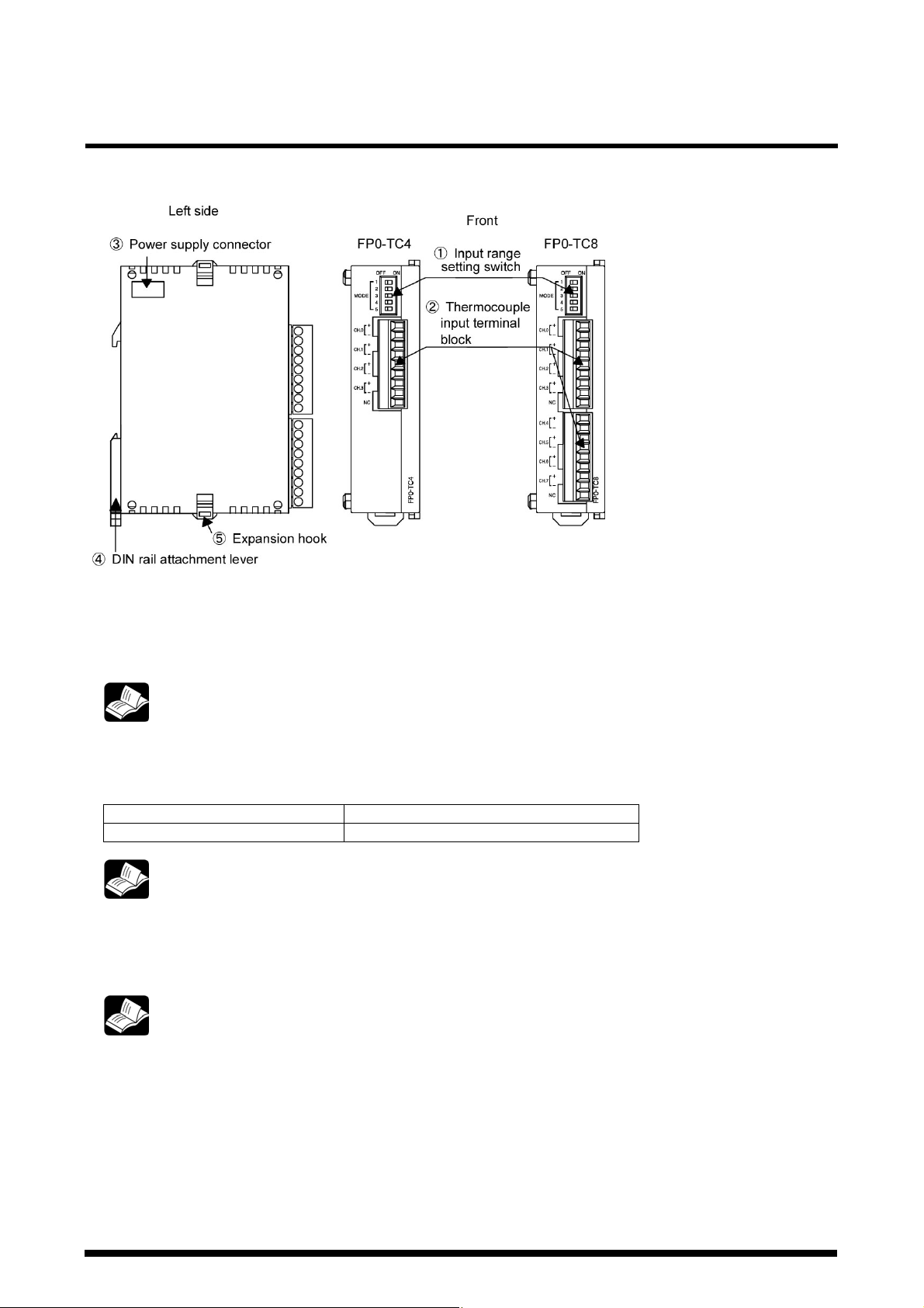
2 Part Names and Functions
- Thermocouple Unit
①Input range setting switch
changes between the input ranges (thermocouple ty pes). Only the same range setting is available for all
the 8 channels. (The setting can not be specified per channel.)
②Thermocouple input terminal block (9-pin)
is made by Phoenix. Model No. is MC1.5/9-ST-3.5 (Part No.: 1840434)
Suitable wires
③Expansion connector
Connects the expansion unit to the internal circuit of the Control Unit.
Reference: “4 Input Range Setting Switch”.
Size Nominal cross-sectional area
AWG# 28 to 16 0.08 mm2 to 0.25mm
Reference: FP0 Hardware Manual “Wiring the Terminal Type”.
FP∑ User’s Manual “Wiring of Terminal Block Type”.
2
FP∑ User’s Manual “Expansion Method of Units for FP0 and FP∑”.
④DIN rail attachment lever (One-touch hook)
The unit can be installed to the DIN rail through one-touch operation.
This is also used for installing the unit to the FP0 Slim Type Mounting Plate (AFP0803).
⑤Expansion hook
Fixes the expansion unit with the Control Unit.
2
Reference: FP0 Hardware Manual “Adding Expansion Units”.
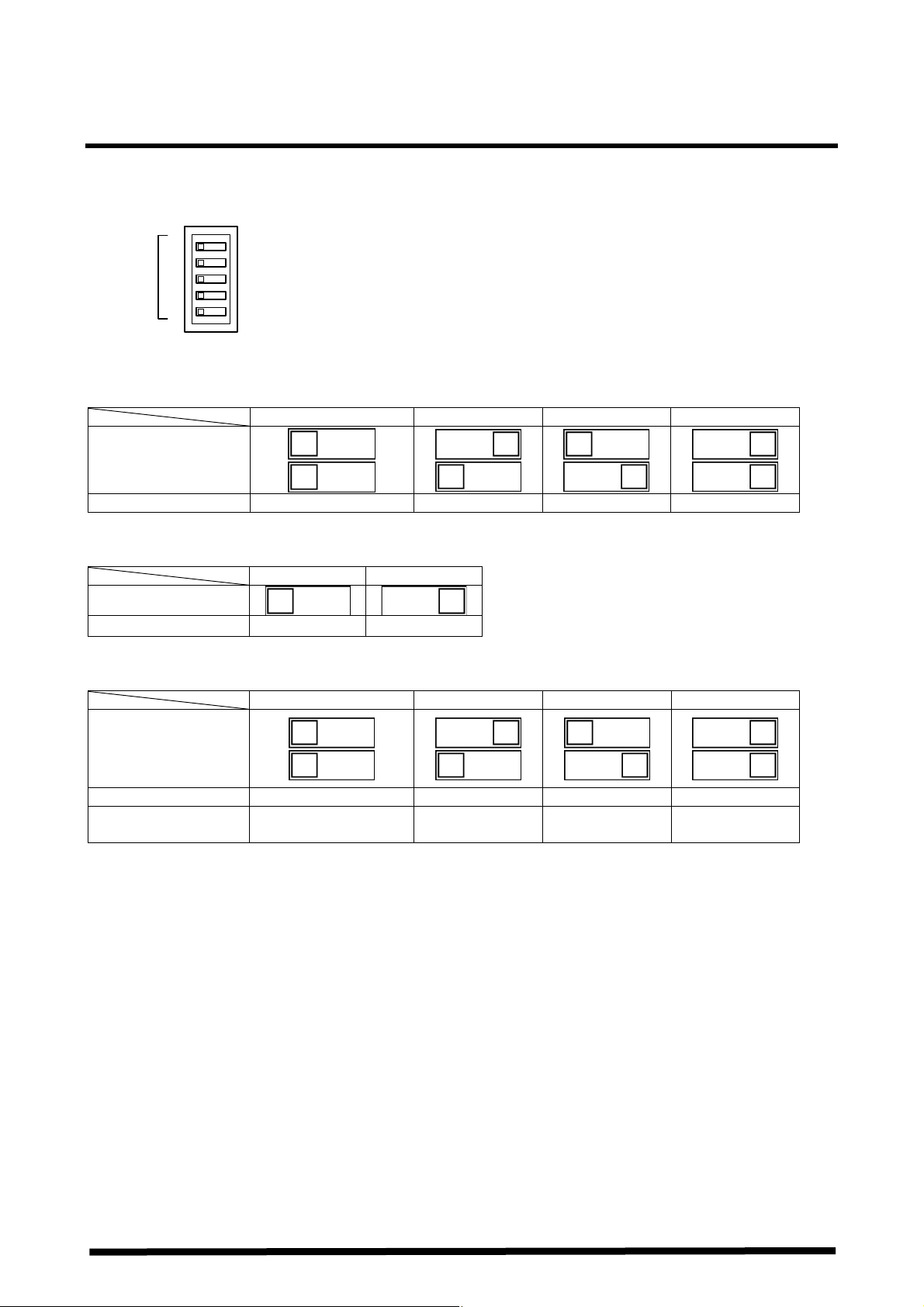
3 Input Range Setting Switch
- Input range setting switch
ON
OFF
1
MODE
(The following switch settings are read once when the Control Unit is turned ON. Any change will not be
reflected even if made while ON.)
1) Input range setting switch
MODE SW 1
2
3
4
5
OFF ON OFF ON OFF ON OFF ON
2
Thermocouple type K J T R
2) Temperature unit switch
OFF ON OFF ON
MODE SW 3
Unit
3) Input channel selection switch
OFF ON OFF ON OFF ON OFF ON
MODE SW 4
5
Input channel CH0, 1 CH0 to CH3 CH0 to CH5 CH0 to CH7
Number of input
channels
* Do not specify it for the FP0-TC4.
℃ ℉
2 4 6 * 8 *
3
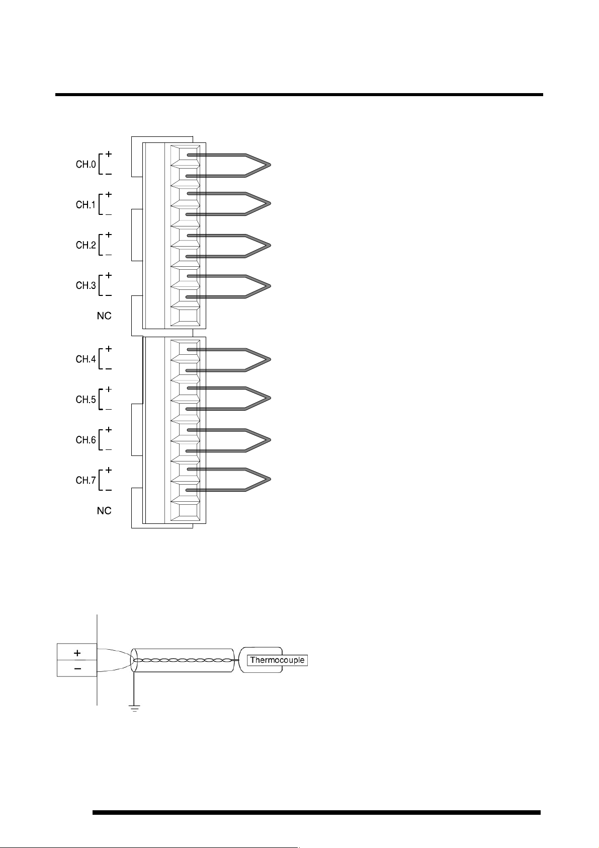
4 Wiring
- Wiring method
- Input line wiring
・Keep the space more than 100mm between the input line and the power line/high-voltage line.
・It is recommended grounding the unit using the insulated compensating wire.
4
 Loading...